1
Instruction Manual
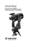
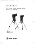
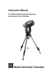
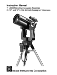
10", 12", 14”, 16" RCX400™ Advanced Ritchey-Chrétien Telescopes
with AutoStar II® Hand Controller and Digital Front Focus
MEADE.COM
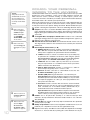
Focusing the Telescope
As you look over your new RCX telescope, one of the first things you will notice is that it has no Focus Knob!
Because this design is of key importance, we are presenting this information on how to focus your telescope on the inside
front cover so that it is immediately accessible.
The Focus Key
All focusing of the RCX400 is performed digitally, using AutoStar II’s Focus key (number key 4).
The Focus key functions as a toggle key:
J Press the Focus key the first time to focus the telescope and to control
the speed at which you focus.
J Press the Focus key again to set and adjust up to nine focus presets.
To change the focus speed:
1. Press the Focus key once. “Focuser: Fast (or the current speed)” displays for two seconds. Use one of the Scroll keys to
scroll through the list of 4 available focus speeds: Fast, Medium, Slow, Fine. Scroll through the list until the speed you
desire displays. Choose a focus speed with which you feel comfortable.
To focus the telescope:
1. Press the Focus key once. “Focuser: Fast (or the current speed)” displays. After two seconds, “Focuser: Position = XX” displays. “XX” stands for a number value in decimal millimeters.
2. Point the telescope at a distant object. Look in the eyepiece and use the Arrow keys until the image in the eyepiece is in
focus.
To exit the focus operation at any time:
1. Press MODE.
If you wish learn how to set focus presets, see page 19.
How to Hot Swap the Autostar II Handbox
You may move the Autostar II handbox from one computer control panel to another, without turning off the RCX control panel.
This is called “hot swapping.”
To hot swap the handbox:
1. Unplug the handbox connector and plug Autostar II into the HBX port of the other computer control panel.
2.
Press and hold the “?” key for two seconds to refresh the display.
CONTENTS
WARNING!
Never use a Meade RCX400 Telescope to
look at the Sun! Looking at or near the Sun
will cause instant and irreversible damage to
your eye. Eye damage is often painless, so
there is no warning to the observer that damage has occurred until it is too late. Do not
point the telescope or its viewfinder at or
near the Sun. Do not look through the telescope or its viewfinder as it is moving.
Children should always have adult supervision while observing.
®
Caution: Use care to install batteries in the
orientation indicated by illustration in the battery slots of the battery holder. Follow battery
manufacturer's precautions. Do not install
batteries backwards or mix new and used
batteries. Do not mix battery types. If these
precautions are not followed, batteries may
explode, catch fire, or leak. Improperly
installed batteries void your Meade warranty.
® The name "Meade" and the Meade logo are trademarks
registered with the U.S. Patent Office and in principal countries throughout the world. "RCX400 " and "AutoStar II" are
trademarks of Meade Instruments Corporation.
Patents:
US 6,304,376
US 6,392,799
US 6,563,636
D 422,610
Patent Pending.
© 2006 Meade Instruments Corporation.
Focusing your Telescope.........................Inside front cover
Quick-Start Guide .......................................................... 4
Telescope Features ...................................................... 8
Autostar II Features ........................................................13
Getting Started ..............................................................16
Parts Listing, How to Attach the Tripod ....................16
How to Assemble the Tripod ....................................16
How to Assemble Your Telescope ............................16
To Attach the Mount..............................................16
To Install the Batteries ..........................................16
To Connect Autostar II and Attach the Holder ......17
To Attach the Diagonal and Eyepiece ..................17
Mounting and Focusing the Viewfinder ....................18
Observing ......................................................................16
Choosing an Eyepiece ..............................................19
Focusing the Telescope ............................................19
Observing by Moving the Telescope Manually..........20
Terrestrial Observing ................................................21
Observing Using Arrow Keys ....................................21
Slew Speeds ............................................................21
Observe the Moon, Astronomical Observing ..........22
To Track an Object Automatically ..............................22
Moving Through Autostar II’s Menus ........................22
Automatic Alignment ................................................22
Observe a Star Using Automatic Tracking ................24
Go To Saturn, Using the Guided Tour ......................24
Basic Autostar II Operation ............................................26
Autostar II Menu Exercises ......................................26
Navigating Autostar II................................................27
Autostar II Menus ........................................................28
Menu Tree ................................................................28
Objects Menu ............................................................29
Event Menu ..............................................................30
Glossary Menu, Utilities Menu ..................................31
Setup Menu ..............................................................32
Hot Button Menus ....................................................36
Advanced Autostar II Features ......................................37
Adding Observing Sites ............................................37
Creating User Objects ..............................................38
Observing Satellites, Landmarks ..............................39
Identify ......................................................................40
Browse ......................................................................41
Alternate Alt/Az Alignment Methods ........................42
To Download the Latest Autostar II Software............43
Periodic Error Correction ..........................................44
Photography ..................................................................45
Optional Accessories......................................................48
Maintenance ..................................................................51
Collimation ....................................................................51
Specifications ................................................................54
Appendix A: Equatorial (Polar) Alignment ......................57
Appendix B: Latitude Chart ............................................62
Appendix C: How to Create Your Own Guided Tour ......63
Appendix D: Training the Drive ......................................67
Appendix E: The Moon Menu ........................................68
Appendix F: Smart Mount ..............................................69
Appendix G: 16" RCX400 Features................................71
Basic Astronomy ............................................................74
QUICK-START GUIDE
Assemble Your Tripod
c
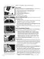
STEP 1: Attach the legs of the tripod to the base:
Slide each leg (1) into a leg receptacle (2) .....
B
STEP 2: Locate the screw in the leg:
....making sure that the screw (3) in the leg.....
d
STEP 3: Slide screw into groove:
....slides into the groove (4) on the receptacle
e
g
STEP 4: Tighten the adjustment lock:
f
f
Rotate the leg attachment lock (6) and tighten to a firm feel.
STEP 5: Set the height of your tripod:
Press and hold down the trigger release lever (5) slide the tripod
leg to the desired length (thereby setting the height of the tripod).
Important Step: Let go of the trigger when the tripod leg is at
the desired length. Unhook the trigger release pin to lock the
leg in place. This step prevents your tripod accidentally slipping out of the position you set .
Perform this procedure for each of the tripod’s legs. The tripod
should now be stable.
4
Attach the Mount to the Tripod
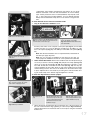
STEP 6: Position the mount over the tripod:
Take note of the T-handle/rod (8) that goes through the tripod
base. The T-handle/rod is spring-mounted into position. Note also
that there is a hole (7) on the bottom side of the mount base.
Lift the mount and position the mount base over the tripod base.
Line up the hole on the mount base over the T-handle rod. When
they are lined up, the rod will “pop up” into the hole.
Caution for 12” and 14” model users: Due to the weight and
size of these products, please use extreme caution whenever
assembling, disassembling, lifting, transporting or storing these
products. Two or more persons should always be used whenever
performing any of these tasks. Disregard for the above warning
could result in serious injury or death.
h
i
STEP 7: Secure the mount with the T-handle:
Rotate the T-handle (9) until the rod is tightened to a firm feel.
j
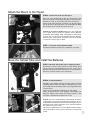
Move the Optical Tube and Install the Batteries
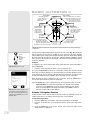
STEP 8: Move the optical tube from its shipping position:
Turn the Dec. lock (10) counterclockwise to unlock the the optical
tube (11) and move it perpendicular the fork arms, to the position
depicted in the image at the left. Turn the Dec. lock clockwise to a
firm feel to relock the position of the optical tube.
1)
STEP 9: Install the batteries:
1!
1#
1@
Assembly of the RCX400 telescope requires eight C-cell (user
supplied) batteries. Remove the battery compartment (13) covers
and carefully remove the battery holders (12), being mindful of the
connector wires.
Insert four user-supplied C-cell batteries into each battery
holder, oriented as shown on the diagram on the battery slots
inside the battery holder. Return the battery holders to their
respective compartments and replace the covers.
Caution: Use care to install batteries as indicated by the battery
compartment. Follow battery manufacturer's precautions. Do not
install batteries backwards or mix new and used batteries. Do not
mix battery types. If these precautions are not followed, batteries
may explode, catch fire, or leak.
Improperly installed batteries void your Meade warranty. Always
remove the batteries if they are not to be used for a long period
of time.
5
QUICK-START GUIDE {CONTINUED}
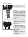
Insert the Telescope Diagonal Mirror and Eyepiece
1%
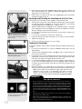
STEP 10: Attach the visual back and diagonal mirror:
1.
1&
1*
Thread the ring of the visual back (16) over the rear cell (15)
and rotate the ring, tightening to a firm feel. Slide the diagonal (18) into the visual back and secure it in place using
the visual back thumbscrew (17).
1^
1(
STEP 11: Insert the eyepiece and remove dust cover:
Remove the UltraWide 24mm eyepiece (19) from its
container and place it in the diagonal mirror. Tighten the thumbscrew (20) located on the diagonal mirror to a firm feel only.
Remove the dust cover (18, Fig. 1a) from the front of the optical
tube assembly (19, Fig. 1a) by gently prying it off.
2)
2!
2@
STEP 12: Plug in the AutoStar II handbox
Check that the power switch on the computer control panel (21)
is in the OFF position. Plug the coil cord of the AutoStar II handbox into the HBX port of the base control panel (22).
Note: The AutoStar II handbox does not require batteries; the
batteries in the telescope supply the power.
Note: You can only plug one handbox into the telescope at a
time; you cannot plug two handboxes into the two control panels
at the same time.
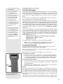
STEP 13: Turn on AutoStar:
2#
2$
2%
2^
6
Press the Power Switch on the computer control panel to the ON
position. The copyright message lights on AutoStar II's LCD display (23).
Press the key prompted by AutoStar II to accept the Sun warning. AutoStar II now displays "Automatic Alignment." You can
then use the Arrow keys (24) to slew (move) the
telescope up, down, right, or left.To change the telescope’s slew
speed, press the Speed key (25) and then the Number keys (26).
"9" is the fastest speed and "1" is the slowest speed.
Point, Focus and Observe
2&
STEP 14: Tighten the R.A. and Dec. Locks:
Move the R.A. lock (27) and tighten to a firm feel. Rotate the Dec.
Lock (28) and tighten to a firm feel, also.
2*
STEP 15: Focus:
2(
To change the focus speed:
Press the Focus key (2() once. “Focuser: Fast (or the current
speed)” displays. Use one of the Scroll keys to scroll through the
list of 4 available focus speeds: Fast, Medium, Slow, Fine. Scroll
through the list until the speed you desire displays (choose a
focus speed with which you feel comfortable).
To focus the telescope:
1. Press the Focus key once. “Focuser: Fast (or the current
speed)” displays. After two seconds, “Focuser: Position = XX” displays. “XX” stands for a number value in decimal millimeters.
2. Point the telescope at a distant object. Look in the eyepiece
and press the Arrow keys until the image in the eyepiece is in
focus.
To exit the focus operation:
1. Press MODE.
STEP 16: Point and Observe:
Sight along the side of the telescope tube to locate an object (if
you wish to attach the viewfinder, see page 18 for more information).
Look through the eyepiece and use AutoStar’s arrow keys to center the object in your eyepiece.
WHERE TO GO FROM HERE...
See pages 8 to 12 to learn about your tripod and telescope’s features.
See pages 13 to 15 to learn about AutoStar II’s features.
See pages 16 to 17 to learn more about your telescope’s
assembly.
See page 18 to learn about your telescope’s viewfinder.
See pages 19 to 21 to learn more about observing and
focusing with your scope.
See pages 22 to 24 to learn how to initialize, align and “go
to” with your telescope.
See pages 28 to 44 to learn about AutoStar’s menus.
See pages 45 to 47 to learn about photography and your
telescope.
See pages 48 to 50 to learn about optional accessories
available for your scope.
7
TELESCOPE FEATURES
2!
B
c
d
e
f
g
h
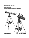
Viewfinder
2)
Fan
1(
Optical tube
Dust cover
1*
Dec. lock
1&
Dec. slow
motion control
1^
Eyepiece
Diagonal
mirror
Rear cell and
2” visual back
OTA control
panel
Right fork arm
1%
AutoStar II
handbox and
tiltable holder
1$
Handles
Left fork arm
Battery
compartments
R.A. lock
i
j
R.A. slow motion control
Base control panel
1)
GPS
Receiver
1!
Dec Setting
Circle
Mounting base
On the left fork arm
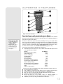
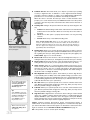
Fig. 1a: The RCX400 Telescope; Dec. Setting Circle (inset).
8
1#
1@
2@
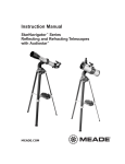
Viewfinder
objective lens
2#
Locking ring
2$
2%
Adjustment
screws
Viewfinder
eyepiece/focuser
2^
Viewfinder
bracket
and dovetail
mount
Fig. 1b: The Viewfinder close up.
2&
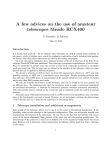
Tripod base with
leg receptacles
2(
Sliding inner leg
extension
3@
T-handle
2*
3)
Tripod
legs
3!
Leg
attachment
lock
Locking latch
and thruster bar
mechanism
Fig. 1c: The Tripod.
A
Off/On
C
H
J
K
USB Ports
Serial port
Autoguider port
12vDC Out
12vDC In
USB Port
AUX port
HBX port
Serial port
Reticle port
HBX port
B
D
E
F
G
L
M
Fig. 1d: The Base Computer Control Panel.
Smart accessory port
N
Fig. 1e: The Optical Tube Assembly (OTA) Computer Control Panel.
9
Caution:
Using products other than
standard Meade accessories
may cause damage to the
telescope’s internal electronics and may void the Meade
warranty.
B Want to learn more
RCX400: YOUR PERSONAL
WINDOW TO THE UNIVERSE
The Meade RCX400 models are extremely versatile, high-resolution telescopes. With
high-precision optics, pushbutton controls, precise GPS alignment, true-level and
North electronic sensors, automatic tracking of celestial objects, periodic error
correction for both axes, and a library of 145,000+ objects in the AutoStar II data base,
the RCX400 models offer observatory-level performance.
Observe the feather structure of an eagle from 50 yards or split a difficult double star.
Focus beyond the Solar System on ancient star clusters, remote galaxies, and stars
recently discovered to have planets orbiting about them. Meade RCX400 telescopes
are capable of meeting the requirements of the most demanding advanced observer.
B
about the eyepieces
available for your
RCX400 telescope?
See OPTIONAL
ACCESSORIES, pages
48, 49, and 50.
b Want to learn more
h
i
10
C
D
about focusing your
telescope? See page
19.
E
Want to learn how to
install the batteries?
See page 16.
F
Want to learn more
about the Right
Ascension and
Declination setting
circles? See page 57.
G
H
I
Eyepiece: Place the 2”, 6-element UltraWide 24mm eyepiece into the diagonal
mirror (3, Fig. 1a) and tighten in place with the diagonal mirror’s thumbscrew (2,
Fig. 1a). The eyepiece determines the magnification of the image collected in the
optical tube.
2" Diagonal Mirror and Eyepiece Thumbscrew: Provides a more comfortable
right angle viewing position. The eyepiece thumbscrew tightens the eyepiece (1,
Fig. 1a) in place. Tighten to a firm feel only.
Rear Cell Port and 2” Visual Back: The visual back threads onto the rear cell.
The diagonal mirror slides into the visual back and is secured by the visual back
thumbscrew.
Base Computer Control Panel (see j):
A. ON/OFF Switch: Turns both computer control panels and AutoStar II
ON or OFF. The red power indicator LED next to the switch illuminates
when power is supplied to the panel and the AutoStar II handbox.
B. 12vDC In: Provides a connection so that the telescope assembly may
be powered from a standard 115v AC home outlet using the optional
RCX AC Wall Adapter with Cable or the optional 12v DC #607 Cigarette
Lighter Adapter. See OPTIONAL ACCESSORIES, pages 48 - 50.
C. 12vDC Out: Use the 12vDC output to power telescope accessories.
This port may be turned on or off with the Aux Port Power option in the
Utilities menu. On is the default value.
D. USB 2.0 High Speed Port: Provides a connection for a USB 2.0
device. This port is typically used to connect to a PC.
E. AUX Port: Provides connection for current Meade accessories. See
OPTIONAL ACCESSORIES, pages 48 - 50.
F. Handbox (HBX) Port: Plug the AutoStar II coil cord into this port.
Important Note: Although both the Base Computer Control Panel and
the OTA Computer Control Panel include an HBX port, only one handbox maybe be plugged in at a time; you cannot plug handboxes into
both ports at the same time.
G. Serial Port: Provides connection with a PC and for current and future
Meade accessories. Your PC can control your RCX400 telescope using
serial commands. Go to the Meade website (www.meade.com) to
download the latest serial commands and device pinouts.
Important Note: Although both the Base Computer Control Panel and
the OTA Computer Control Panel include a serial port, only one may be
used at a time; you cannot plug into both ports at the same time.
Handles: Use to lift optical tube assembly or to rotate the telescope when
attached to the tripod. Attach the AutoStar II handbox holder to one of the handles (5, Fig. 1a).
Left Fork Arm: The left side of the heavy-duty mount that holds the optical tube
securely in place (see 1%).
Battery Compartments: Insert four user-supplied C-cell batteries into each compartment (one compartment on each fork arm; eight batteries total).
Right Ascension (R.A.) Slow-Motion Control: Make fine adjustments in the Right
Ascension, i.e., the horizontal axis, by turning this control with the R.A. Lock (see
Definitions
Throughout this manual,
you will notice the terms
"Alt/Az," "Right
Ascension," and
"Declination." Alt/Az or
more properly, altitudeazimuth (or altazimuth), is
frequently used to refer to
altitude or Declination (the
up-and-down vertical movement of the telescope) and
azimuth or Right Ascension
(the side-to-side horizontal
movement of the telescope). Right Ascension is
abbreviated as "R.A." and
Declination as "Dec."
1#) in the unlocked position. Set the R.A. Lock to a "partially locked" position to create
a comfortable drag for the R.A. Slow Motion Control.
Caution: Do not operate the R.A. Slow Motion Control with the R.A. Lock
in the fully locked position, as such operation may result in damage to the
internal gear system and also cause you to lose alignment.
Optical Tube Assembly (OTA) Computer Control Panel (also see e):
j
1)
1!
1@
1#
1$
1%
Caution:
When loosening the Dec.
lock, be sure to support the
optical tube (19, Fig. 1a).
The weight of the tube
could cause the tube to
swing suddenly.
1^
1&
H. USB Port: Provides 3 connections for USB 2.0 devices. This port is
typically used to connect to CCD cameras, such as Meade’s LPI or
Deep Sky Imager. See OPTIONAL ACCESSORIES, pages 48 - 50.Your
PC can control your RCX400 telescope using serial commands. Go to
the Meade website (www.meade.com) to download the latest serial
commands and device pinouts.
J. Serial Port: Provides connection with a PC and for current and future
Meade accessories. Your PC can control your RCX400 telescope using
serial commands. Go to the Meade website (www.meade.com) to
download the latest serial commands and device pinouts.
Important Note: Although both the Base Computer Control Panel and
the OTA Computer Control Panel include a serial port, only one may be
used at a time; you cannot plug into both ports at the same time.
K. Autoguider Port: Plug the optional autoguider into this port. See the
instruction sheet that came with your autoguider for more information.
Also see OPTIONAL ACCESSORIES, pages 48 - 50.
L. Reticle Port: Plug the optional reticle eyepiece into this port. Control
the reticle through the AutoStar II menus. See HOT BUTTON MENUS
page 36. Also see OPTIONAL ACCESSORIES, pages 48 - 50.
Note: See the instruction sheets that are included with the reticle and
the autoguider for more details.
M. Handbox (HBX) Port: Plug the AutoStar II coil cord into this port.
Important Note: Although both the Base Computer Control Panel and
the OTA Computer Control Panel include an HBX port, only one handbox maybe be plugged in at a time; you cannot plug handboxes into
both ports at the same time.
N. Smart Accessory Port: Provides connection for future Meade accessories.
GPS Receiver: Receives information transmitted from Global Positioning System
satellites. See page 25 for more information.
Declination (Dec.) Setting Circle (on left fork arm): See APPENDIX A, page 57,
for detailed information.
Mounting Base: Attach to the tripod base (see 2&). See page 16 for mounting
instructions.
Right Ascension (R.A.) Lock: Controls the manual horizontal rotation of the
telescope. Turning the R.A. lock counterclockwise unlocks the telescope, enabling
it to be freely rotated by hand about the horizontal axis. Turning the R.A. lock
clockwise locks the telescope, prevents the telescope from being rotated manually, and engages the horizontal motor drive for AutoStar II operation.
AutoStar II Handbox and Tiltable Holder: Controls all the electronic functions
of the telescope. See pages 13 - 15 for detailed information. You may have
noticed that there is no manual focus knob; all focus is achieved by using the
AutoStar handbox. Attach the holder to one of the handles (see f). Holds your
handbox in a convenient location.
Right Fork Arm: The right side of the heavy-duty mount that holds the optical
tube securely in place (see g).
Declination (Dec.) Slow-Motion Control: Make fine adjustments in
Declination(altitude) by turning this control with the Dec. Lock (see 1& below) in
the locked position. In order for this control to operate properly, power must be off.
Dec. Lock: Controls the manual vertical movement of the telescope. Turning the
Dec. lock counterclockwise unlocks the telescope enabling it to be freely rotated
by hand about the vertical axis. Turning the Dec. lock clockwise (to a firm feel
11
only) prevents the telescope from being moved manually, but engages the vertical motor drive for AutoStar II operation.
1*
Dust Cover: Gently pry the dust cover from the front lens of the telescope.
Note: The dust cover should be replaced after each observing session and the
power turned off to the telescope.
1(
2)
Optical Tube: The main optical component that gathers the light from distant
objects and brings this light to a focus for examination through the eyepiece. The
tube contains the primary mirror which floats on a layer of adhesive that results
in zero-stress to the glass and no distortion to the optics.
Fan: AutoStar controls the fan operation. The amount of time required to stabilize the temperature will be dependent upon ambient conditions including the
observation site and preexisting condition of the telescope. The fan should be
activated at the beginning of the observation session to accelerate the temperature stabilization. As soon as the optics have reached an equilibrium with the
environment the fan should be turned off. Fan operation time should range
between 5 and 25 minutes. While it is permissible to run the fan continuously it is
not recommended because the very slight vibration of the fan may cause noticeable movement of the objects observed in the sensitive optics.
The Viewfinder
2!
2! Want to learn more
about attaching and
aligning the
viewfinder? See page
18.
2@
2#
2$
2%
2^
8 x 50mm Viewfinder: A low-power, wide-field sighting scope with crosshairs
that enables easy centering of objects in the telescope eyepiece.
Viewfinder Objective Lens: Gathers the light for the viewfinder.
Viewfinder Locking Ring: Locks the objective lens into place. Unlock to adjust
the focus of the objective lens. See page 18 for details.
Viewfinder Adjustment Screws: Use these six screws to adjust the alignment
of the viewfinder.
Viewfinder Eyepiece/Focuser: The eyepiece magnifies the image collected by
the viewfinder’s objective lens. Rotate the eyepiece to focus.
Viewfinder Bracket and Mounting: Holds the viewfinder in place.
The Tripod
2&
2*
2(
3)
3!
3@
12
Tripod Base with Leg Receptacles: Attach the mounting base (see 1@) to the
tripod base. See page 16 for mounting instructions. Slide the tripod legs into the
leg receptacles.
Leg Attachment Lock: Secures the tripod legs into the leg receptacles.
Sliding Inner Leg Extension: Inner leg extension slides in or out to adjust the
tripod height.
Variable Height Tripod Legs: Supports the optical tube assembly.
Locking Latch and Thruster Bar: Lift latch to release inner leg extensions. Let
go of latch to lock inner extension in place. See page 16 for mounting
instructions. Also see Fig. 8.
T-Handle: Thread into the mounting base and tighten to a firm feel to keep the
tripod stable.
AUTOSTAR II FEATURES
1
2
3
5
6
7
K
4
8
9
J
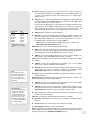
Fig. 2: The Autostar II Handbox.
Tour the Cosmos with Just the Push of a Button
Control of the RCX400 telescope models is through the operation of the standard
Autostar II system. Nearly all functions of the telescope are accomplished with just a
few pushes of Autostar II’s buttons.
Want to learn more about
downloading the latest
updates of Autostar II
software from the
Meade website? Go to
www.meade.com/support/auto.html for complete instructions. Also
see page 43.
Because the Autostar II system uses flash (rewritable) memory, your system will be
able to grow when new features and enhancements become available. Download the
latest satellite data, star and object catalogs, tours, serial commands list, and software
revisions, directly from the Meade website (www.meade.com). (Requires the optional RCX400 Interface Cable. See OPTIONAL ACCESSORIES, pages 48 - 50.)
Some of the major features of the Autostar II system are:
J
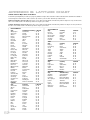
Automatically move the telescope to any of the more than 180,000 objects stored
in the object library, including:
Library
# of Objects
New General Catalog (NGC):
7,840
Index Catalog (IC):
5,386
Messier Catalog (M):
110
109
Caldwell Catalog:
227
Named Objects:
400
Herschel Catalog:
2,712
Abell Catalog of Galaxy Clusters:
Arp Catalog of Irregular Galaxies:
645
12,940
Uppsala Galaxy Catalog:
12,939
Morphological Catalog of Galaxies:
28,484
General Catalog of Variable Stars:
SAO:
17,191
17,325
Hipparcos Star Catalog:
....plus the Lunar 100, the Washington Star Catalog, the Gliese Catalog, and more!
J
J
J
J
J
J
J
Focus your telescope’s eyepiece.
Take a guided tour of the best celestial objects to view on any given night of the year.
Control your RCX400 with your PC using an RS232 or USB interface.
Align your telescope automatically using GPS (Global Positioning System).
Access a glossary of astronomical terms.
Mount the telescope in the “Alt/Az” mode (i.e, altitude—azimuth, or
vertical—horizontal mode) for fully automatic tracking of celestial objects.
Collimate your telescope using only AutoStar II’s Arrow keys.
13
The Autostar II system provides control of virtually every telescope function. The
Autostar II handbox has soft-touch keys designed to have a positive feel. The LCD
(Liquid Crystal Display) is backlit with red LEDs (Light Emitting Diodes) for easy viewing in the dark. The backlit display, key arrangement, and sequential menu structure
make Autostar II extremely user friendly.
B
c
d
e Want to learn more
e
about using the GO TO
function? See page 24.
Want to learn how to
perform a spiral
search? See page 24.
f
2-Line LCD Display: This screen displays Autostar II's menus and information
about the telescope.
• Top line: Lists the primary menu.
• Bottom line: Displays other menus that may be chosen, menu options,
telescope status, or information about a function that is being performed.
ENTER Key: Press to go to the next menu level or to choose an option in a menu.
The ENTER key is similar to the RETURN or ENTER key on a computer. See
MOVING THROUGH AUTOSTAR II'S MENUS, page 22 and BASIC AUTOSTAR II
OPERATION, pages 26 - 27
MODE Key: Press to return to the previous menu or data level. The top menu
level is “Select Item." The MODE key is similar to the ESCAPE key on a computer.
Note: Pressing MODE repeatedly while in the “Select Item” level moves
Autostar II to the topmost screen: “Select Item: Object.”
Note: If MODE is pressed and held for two seconds or more, information
about the telescope's status displays. When the status displays, press the
Scroll keys (7, Fig. 2) to display the following information:
• Right Ascension and Declination (astronomical) coordinates
• Altitude (vertical) and Azimuth (horizontal) coordinates
• Local Time and Local Sidereal Time (LST)
• Timer and Alarm Status
• Date
• Site coordinates
• Battery status
Press MODE again to return to the previous menu.
GO TO Key: Press to slew (move) the telescope to the coordinates of the currently selected object. While the telescope is slewing, the operation may be aborted at any time by pressing any key except GO TO. Pressing GO TO again
resumes the slew to the object. Also, press during the alignment or GO TO procedures to activate a "spiral search."
Arrow Keys: The Arrow keys have several functions. Press an Arrow key to slew
the telescope in a specific direction (up, down, left, and right), at any one of nine
different speeds. See SLEW SPEEDS, page 21. Use the Up and Down Arrow keys
to move the telescope vertically up and down. The Left Arrow key rotates the telescope horizontally counterclockwise, while the Right Arrow key rotates it clockwise
(unless reversed for Southern Hemisphere use).
Also, use the Arrow keys to scroll through numbers 0 through 9 and the alphabet.
The Down Arrow key begins with the letter "A;" the Up Arrow key begins with digit
"9."
Additionally, use the Arrow keys to move the cursor across the display: Use the
Right or Left Arrow key (5, Fig. 2) to move the cursor from one number to the next
in the display.
SPEED
1
Want to learn more
about changing slew
speeds? See page 21.
14
g
Number Keys: Press to input digits 0 to 9. Each Number key also has a specific function, which is printed on each key (these are commonly known as "hot buttons"—see page 36):
1 SPEED: Changes the slew speeds. To operate, press Speed and then a
Number key (1 is the slowest speed, 9 is highest speed).
2 CALD (Caldwell): Press to display the Caldwell catalog on the Autostar II
handbox.
3 M (Messier): Press to display the Messier catalog library.
4 FOCUS: Toggles between two functions. The first press allows you to
change the focus and focus speed. The next press allows you to create
presets that tell the telescope where to focus.
5 SS: Press to display the Solar System library.
6 STAR: Press to display the Star library.
7 RET (Reticle): Press to display the Reticle Control menu.
8 IC: Press to display the Index Catalog library.
9 NGC (New General Catalog): Press to display the NGC catalog library.
0 LIGHT: Press to turn on and off the red utility light on the top of the handbox.
FOCUS
4
Want to learn
more about the Focus
menu? See page 19.
RET
7
Want to learn
more about the Reticle
menu? See page 36.
h
Scroll Keys: Press to access options within a selected menu. The menu is displayed on the first line of the screen. Options in the menu are displayed, one at a
time, on the second line. Press the Scroll keys to move through the options. Press
and hold a Scroll key to move quickly through the options.
The Scroll keys also control the speed of text scrolling on the Autostar II display.
When text is scrolling, press and hold the Up Scroll key for a faster display speed
and the Down Scroll key for a slower display speed.
Tip:
When an astronomical
term appears in [brackets], press ENTER for a
definition or more detailed
information. Press MODE
to return to the scrolling
Autostar II Help display.
If a celestial object's
name appears in brackets
(and your telescope is
aligned), press ENTER
and then GO TO to slew
the telescope to the object.
i
? Key: Press to access the "Help" file. "Help" provides on-screen information on
how to accomplish whatever task is currently active.
Press the ? key and then follow the prompts on the display to access details of
Autostar II functions in the Help feature. The Help system is essentially an onscreen instruction manual.
If you have a question about an Autostar II operation, e.g., INITIALIZATION,
ALIGNMENT, etc., press the ? key and follow the directions that scroll on the second line. When satisfied with the Help provided, press MODE to return to the original screen and continue with the chosen procedure.
j
1)
1!
Coil Cord Port: Plug one end of the Autostar II coil cord (10, Fig. 2) into this port
located at the bottom of the Autostar II handbox.
Coil Cord: Plug one end of the Autostar II coil cord into the HBX port (F, Fig. 1d)
of the computer control panel of the telescope and the other end into the Autostar
II coil cord port. See j above.
Utility Light: Use this built-in red light to illuminate star charts and accessories
without disturbing your eye's adaptation to darkness. Press "0" to turn the light on
and off.
RCX400 TIPS
Join an Astronomy Club, Attend a Star Party
One of the best ways to increase your knowledge of astronomy is to join an astronomy
club. Check your local newspaper, school, library, or telescope dealer/store to find out if
there’s a club in your area.
At club meetings, you will meet other astronomy enthusiasts with whom you will be able
to share your discoveries. Clubs are an excellent way to learn more about observing the
sky, to find out where the best observing sites are, and to compare notes about telescopes, eyepieces, filters, tripods, and so forth.
Often, club members are excellent astrophotographers. Not only will you be able to see
examples of their art, but you may even be able to pick up some “tricks of the trade” to
try out with your RCX400 telescope. See page 45 for more information about photography with the RCX400.
Many groups also hold regularly scheduled Star Parties at which you can check out and
observe with many different telescopes and other pieces of astronomical equipment.
Magazines such as Sky & Telescope and Astronomy print schedules for many popular
Star Parties around the United States and Canada.
15
GETTING STARTED
c
Parts Listing
Getting the telescope ready for first observations requires only a few minutes. When
first opening the packing box, note carefully the following parts:
J
J
J
J
J
J
J
B
Fig. 7: Attach leg (1) to leg
receptacle (2).
RCX400 Telescope with fork mount system and GPS Receiver
AutoStar II handbox and interface coil cord; handbox holder
8 x 50mm viewfinder assembly
2" diagonal mirror and 2” visual back barrel
Series 5000 UltraWide 24mm eyepiece
Variable height tripod
USB cable and software CD ROM
How to Assemble the Tripod
Remove the parts of the tripod from the shipping carton. Assembly of the tripod will
take just a few minutes.
d
To assemble the tripod:
1. Slide a leg (1) into a leg receptacle (Fig. 7), making sure that the screw (3) in the
leg (Fig. 8) slides into the groove (4) on the receptacle (Fig. 9).
Fig. 8: Slide the screw (3)...
2.
Rotate the leg attachment lock (6) and tighten to a firm feel.
3.
Press and hold down the trigger release lever (5) slide the tripod leg to the
desired length (thereby setting the height of the tripod). See Fig. 11. Let go of the
trigger when the tripod leg is at the desired length.
5.
Repeat steps 1 through 4 for the other two tripod legs. The tripod should now be
stable.
How to Assemble Your Telescope
e
Fig. 9: ... into groove on the
receptacle (4).
g
f
Fig. 10: Tighten the leg adjustment
lock (6).
f
Fig. 11: Lift the trigger lever (5) so
that you can adjust the height of the
tripod leg.
16
The telescope’s fork mounting base attaches directly to the tripod. The telescope in
this way is mounted in an “altazimuth” (“altitude-azimuth,” or “vertical-horizontal”) format. It is recommended that two people attach the mount to the tripod.
Caution for 12” and 14” model users: Due to the weight and size of
these products, please use extreme caution whenever assembling,
disassembling, lifting, transporting or storing these products. Two or more
persons should always be used whenever performing any of these tasks.
Disregard for the above warning could result in serious injury or death.
Note: The field tripod also can be used in conjunction with the optional
equatorial wedge (see your wedge’s instruction sheet for more
information) for long exposure astrophotography.
The tripod base comes with a tangent arm attached for use with the superwedge.
To attach the mount:
1. Take note of the T-handle under the tripod base. The T-handle is spring-mounted
into position. Note also that there is a hole on the bottom side of the mount base.
2. Lift the mount and position the mount base over the tripod base. Line up the hole
on the mount base over the T-handle rod. When they are lined up, place the
mount down onto the rod and the rod will “pop up” into the hole (Fig. 12).
3. Rotate the T-handle until the rod is tightened to a firm feel (Fig. 13).
To install the batteries:
Assembly of the RCX400 telescope requires eight C-cell (user-supplied) batteries or
the optional RCX AC Wall Adapter to a standard 115v home outlet . Plug the adapter
into the 12vDC In port of the computer control panel (B, Fig. 1d).
1. Turn the Dec. lock (17, Fig. 1a) counterclockwise to unlock the the optical tube
(19, Fig. 1a). Move the optical tube to the position depicted in Fig. 1a and turn
the Dec. lock clockwise to a firm feel to relock the position of the optical tube.
2.
Remove the battery compartment covers (7, Fig. 1a) and carefully remove the
battery holders, being mindful of the connector wires (Fig. 15). Insert four usersupplied C-cell batteries into each battery holder, oriented as shown on the diagram on the battery slots inside the battery holder. Return the battery holders to
their respective compartments and replace the covers.
Caution: Use care to install batteries as indicated by the battery
compartment. Follow battery manufacturer's precautions. Do not install
batteries backwards or mix new and used batteries. Do not mix battery
types. If these precautions are not followed, batteries may explode, catch
fire, or leak. Improperly installed batteries void your Meade warranty.
Always remove the batteries if they are not to be used for a long period of
time.
To attach AutoStar II and connect the handbox holder
1. Plug in the AutoStar II handbox: Check
1$
h
i
1#
1@
Fig. 12: Line up the T-handle rod (8)
with the hole on the base (7).
A
Fig. 16: Locations of the On/Off switch and the
HBX port on the Computer Control Panel located on the base of the telescope.
j
1%
1^
B
Fig. 17a: Handbox holder: (14) Lock
knob; (15) Clamp; (16) Holder.
Fig. 17b: Handbox holder attached to
fork arm handle.
that the power switch on the computer control panel (12, Fig. 16) is in the OFF
position. Plug the coil cord of the AutoStar II handbox into the HBX port of the
base control panel (13, Fig. 16) or the HBX port of the OTA control panel (M, Fig.
1e).
Fig. 13: Tighten the T-handle (9) to a
“firm feel.”
1)
1!
Note: The AutoStar II handbox does not require batteries; the batteries in
the telescope supply the power.
Note: You can only plug one handbox into the telescope at a time; you
cannot plug in two handboxes into the two control panels at the same time.
2. Attach the handbox holder: Remove the handbox holder from the plastic bag. If
necessary, loosen the lock knob (14, Fig. 17a) and place the clamp (15, Fig. 17a)
about one of the fork arm handles (15, Fig. 1a). Tighten the lock knob to a firm
feel. Slide the AutoStar II handbox into the holder (16, Fig. 17a).You may also
snap the handbox into the holder: Slide one side of the handbox into the holder
and then firmly press the other side of the handbox into the holder until it snaps
in place. Adjust the tilt of of the holder by loosening the lock knob and then moving the holder clamp to the desired angle. Retighten the lock knob.
To attach the diagonal mirror and the eyepiece
1&
Fig. 14: Loosen the R.A. (11) and
Dec. (10) locks to Move the optical
tube from its shipping position.
2)
1&
1(
1*
Fig. 18: Rear cell
(17).
Fig. 15: Battery installation.
1.
Fig. 19: Thread the ring of the
visual back (18) onto the rear
cell (17). Slide diagonal into the
visual back and secure with
thumbscrew (19).
2!
Fig. 20: Slide eyepiece (20)
into the diagonal mirror and
tighten thumbscrew (21).
Attach Visual back and Diagonal mirror: Thread the ring of the visual back over
the rear cell and rotate the ring, tightening to a firm feel (see Figs. 18 and 19) .
Slide the diagonal into the visual back and secure it in place using the visual back
thumbscrew.
17
2.
Insert eyepiece: Remove the UltraWide 24mm eyepiece from its container and
slide it in the diagonal mirror. Tighten the thumbscrew (Fig. 20) located on the
diagonal mirror to a firm feel only.
3.
Remove dust cover: Remove the dust cover (18, Fig. 1a) from the optical tube
assembly by gently prying it off.
Mounting and Focusing the Viewfinder for the First Time
2@
2$2#
Fig. 21: Viewfinder bracket assembly:
Slide the track (23) into the mounting
slot (22). Tighten the thumbscrews
(24) to secure.
2%
2^
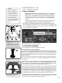
The first time you mount and focus the viewfinder, follow the these steps:
1.
Slide the track on the bottom of the viewfinder bracket into the slot in the viewfinder mounting assembly. See Fig. 21. To secure the viewfinder to the mounting
assembly, tighten the two thumbscrews to a firm feel only.
2.
Slide the viewfinder tube (see Fig. 22) into the viewfinder bracket. Loosely tighten the adjustment screws (see Fig. 23). You will use the adjustment screws to
align the viewfinder (see the next section below).
2.
Look through the viewfinder. Rotate the eyepiece/focuser until you sharply focus
the crosshairs.
3.
Loosen (rotate clockwise) the objective lens locking ring.
4.
Rotate the objective lens until you sharply focus on an object located at infinity.
5.
Tighten the locking ring.
6.
You may now rotate the eyepiece to focus on objects.
Aligning the Viewfinder
To align the viewfinder, perform steps 1 through 4 during the daytime; perform step 5
at night.
2&
Fig.22: 8x50 Viewfinder tube:
Objective lens (25), eyepiece/focuser
(26) and locking ring (27).
2*
1.
If you have not already done so, insert the UltraWide 24mm eyepiece into the
diagonal mirror.
2.
Unlock the R.A. (13, Fig. 1a) and Dec. (17, Fig. 1a) locks so that the telescope
moves freely on both axes.
3.
Point the telescope at some well-defined and stationary land object at least 200
yards distant, such as the top of a telephone pole or street sign. Center the object
in the telescope eyepiece. Re-tighten the R.A. and Dec. locks.
4.
Look through the viewfinder eyepiece and loosen or tighten, as appropriate, one
or more of the viewfinder adjustment screws (see Fig. 23) until the viewfinder
crosshairs are precisely centered on the object you previously centered in the telescope eyepiece.
5.
Check this alignment on a celestial object, such as the Moon or a bright star, and
make any necessary refinements, using the method outlined in steps 2 through 4.
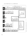
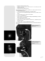
Note: Seeing conditions vary widely from night-to-night and site-to-site.
Turbulence in the air, even on an apparently clear night, can distort
images. If an image appears fuzzy and ill-defined, back off to a lower
power eyepiece for a more well-resolved image (see Fig. 24a and 24b).
RCX400 TIPS
Fig. 23: Viewfinder adjustment screws
(28).
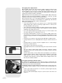
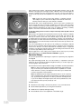
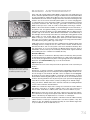
Too Much Power?
Can you ever have too much power? If the type of power you’re referring to is
eyepiece magnification, yes, you can! The most common mistake of the beginning observer is to “overpower” a telescope by using high magnifications which
the telescope’s aperture and atmospheric conditions cannot reasonably support.
Keep in mind that a smaller, but bright and well-resolved image is far superior to
one that is larger, but dim and poorly resolved (see Figs. 24a and 24b). Powers
above 400X should be employed only under the steadiest atmospheric conditions.
Fig. 24a & 24b: Jupiter; examples of
the right amount of magnification and
too much magnification.
18
Autostar II can calculate the best eyepiece for you to use. Try out the “Eyepiece
Calc” feature in the Utilities menu.
Most observers should have three or four additional eyepieces to achieve the full
range of reasonable magnifications possible with the RCX400 telescopes. See
OPTIONAL ACCESSORIES, pages 48 - 50.
OBSERVING
Important Note:
Objects appear upside-down
and reversed left-for-right
when observed in the
viewfinder. Objects viewed
through the telescope eyepiece when inserted into the
diagonal prism assembly
appear right-side-up, but
reversed left-for-right.
Choosing an Eyepiece
This image inversion is of no
consequence when observing astronomical objects and,
in fact, all astronomical telescopes yield inverted
images.
Low power eyepieces offer a wide field of view, bright, high-contrast images, and eye
relief during long observing sessions. To find an object with a telescope, always start
with a lower power eyepiece such as the UltraWide 24mm. When the object is located and centered in the eyepiece, you may wish to switch to a higher power eyepiece
to enlarge the image as much as practical for prevailing seeing conditions. For information about optional eyepieces for your telescope, see OPTIONAL ACCESSORIES,
pages 48 - 50.
During terrestrial observing,
where a fully-correctly-oriented image (right-side-up and
correct left-for-right) is desirable, an optional #928 45°
Erecting Prism and optional
1.25” eyepiece holder are
available. See OPTIONAL
ACCESSORIES, pages 48 50.
A telescope’s eyepiece magnifies the image formed by the telescope’s main optics.
Each eyepiece has a focal length, expressed in millimeters, or “mm.” The smaller the
focal length, the higher the magnification. For example: An eyepiece with a focal
length of 9mm has a higher magnification than an eyepiece with a focal length of
26mm.
Your telescope comes supplied with an UltraWide 24mm eyepiece which gives a
wide, comfortable field of view with high image resolution.
The power, or magnification of a telescope is determined by the focal length of the telescope and the focal length of the eyepiece being used (an eyepiece's focal length is
printed on the side of the eyepiece). To calculate eyepiece power, divide the telescope's focal length by the eyepiece's focal length. For example: A 24mm eyepiece is
supplied with RCX400 models. The focal length of the 12" f/8 RCX400 is 2438mm (see
SPECIFICATIONS, pages 54 - 56).
Eyepiece Power = Telescope focal length ÷ Eyepiece focal length
Eyepiece Power = 2438mm ÷ 24mm
Eyepiece Power = 102
The eyepiece power, or magnification is therefore 102X (approximately).
Note: For a list of magnification ratings of the eyepieces available for the
RCX400 telescopes, see OPTIONAL ACCESSORIES, pages 48 - 50.
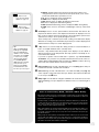
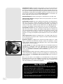
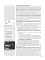
Focusing the Telescope
All focusing of the RCX400 is performed digitally, using AutoStar II’s Focus key
(number key 4). The Focus key functions as a toggle key:
J Press the Focus key the first time to focus the telescope eyepiece and to control
the speed at which you focus.
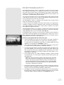
FOCUS
KEY
Fig. 25: Focus is all-digital, using the
Focus key (the #4 Number key) of
the AutoStar II handbox.
J Press the Focus key again to set and adjust up to nine focus presets.
To change the focus speed:
1. Press the Focus key once. “Focuser: Fast (or the current speed)” displays for
two seconds. Use one of the Scroll keys to scroll through the list of 4 available
focus speeds: Fast, Medium, Slow, Fine. Scroll through the list until the speed
you desire displays. Choose a focus speed with which you feel comfortable.
To focus the telescope eyepiece:
1. Press the Focus key once. “Focuser: Fast (or the current speed)” displays. After
two seconds, “Focuser: Position = XX” displays. “XX” stands for a number value
in decimal millimeters.
2. Point the telescope at a distant object. Look in the eyepiece and use the Arrow
keys until the image in the eyepiece is in sharp focus.
Presets:
If you “Park” your telescope, you do not have to refocus the telescope each time you
use it. Nine preset focus positions are available, and they operate much like presets
on a car radio—everyone can have their own favorite station, or in this case, their own
personalized focus. You can set one preset to take into account your own eyesight,
one for your observing partner (who may wear glasses), one for your camera’s focus,
and so forth.
Three preset menus are available. Use the Define Preset menu to assign a preset,
use the GoTo Preset menu to select a preset you have previously assigned, and use
19
Sync On Preset menu if you do not park your telescope (this menu will reset all your
focus presets after you turn off and turn on your scope again ).
To define a preset:
1. Point the telescope at a distant object, press FOCUS and use the Up and Down
Arrow keys to focus the telescope until the object is sharply focused as previously
explained.
2. Press the Focus key again (FOCUS toggles between the Focus menu and the
Preset menu). “Focuser Preset: Go To” displays. Use a Scroll key and scroll down
the list of options until “Focuser Preset: Define Preset” displays. Press ENTER.
3. A list of presets displays. If no preset is currently assigned, “1- Unnamed” displays
(followed by 2- Unnamed, up to 9 - Unnamed).
4. Use the up and down Scroll keys to scroll through the alphabet and the right and
left Arrow keys to move to cursor right or left across the display.
5. When you have finished typing in a name and focusing the telescope, press
ENTER. That number preset is now defined. You can enter 9 names. For example, you may enter “Joe,” “Jill,” “Deep Sky Imager” and so forth.
6. To select one of these presets, you will use the “Focuser Preset: Go To” menu.
To select a previously defined focus preset
1. Press the Focus key twice. “Focuser Preset: Go To Preset” displays. Press
ENTER to select this menu.
2. Use a Scroll key and scroll down the list of previously defined presets. When the
desired preset displays (for example, “Deep Sky Imager”), press ENTER.
Important Note: If you do not park your telescope, you will need to select
one of the presets and refocus your telescope using the Sync On menu.
See TO SYNC ON A FOCUS PRESET below.
To sync on a focus preset
If you park your telescope, AutoStar II remembers all the focus positions you
defined as presets and you will not need this menu.
If you do not park your telescope, you will need to select just one of the presets and
refocus your telescope using the Sync On menu. Then AutoStar II will then reset all
the other presets back to the focus preset positions you previously defined.
1. Press the Focus key twice. “Focuser Preset: Go To Preset” displays. Use a Scroll
key and scroll until “Focuser Preset: Sync On Preset” displays and press ENTER
to select this menu.
2. Use a scroll key to choose one of the previously entered presets from this list (the
most likely preset you will choose will be one that accounts for your own
eyesight).
3. Use the Up or Down Arrow keys to focus the eyepiece.
4. Press ENTER. AutoStar II now “remembers” the relative focus positions of the
eyepiece.You can now choose any preset and it will be correctly focused.
To exit the focus operation at any time:
1. Press MODE.
Observing by Moving the Telescope Manually
Note:
Viewing conditions vary widely from night-to-night and siteto-site. Turbulence in the air,
even on an apparently clear
night, can distort images.
Low-power eyepieces, such
as the UltraWide 24mm supplied with your telescope, are
better suited to resolving
images in poor viewing conditions.
If you wish to observe a distant land object, such as a mountain top or a bird, you can
observe by merely pointing the telescope and looking through the eyepiece.
1. Loosen the telescope’s R.A. lock (13, Fig. 1a) and Dec. lock (17, Fig. 1a).
2. Move your telescope to observe distant street signs, mountains, trees, and other
structures. Use your viewfinder to help site-in on an object.
3. Center the object in the viewfinder’s crosshairs and then in the telescope eye
piece. When the object is centered in your eyepiece, remember to re-tighten the
R.A. and Dec. locks.
4. To move telescope in the R.A. and Dec. axes again, remember to loosen the R.A.
lock and tighten the Dec. lock. Then rotate the manual slow motion control knobs
(10, Fig. 1a) and (16, Fig. 1a) .
5. Practice digitally focusing on objects.
See FOCUSING THE TELESCOPE, page 19.
6.
20
Once you get a feel for how your telescope moves and focuses, try to view some-
You can also observe stars and objects in the night sky using this method, but note
that objects begin to slowly drift across the eyepiece field. This motion is caused by
the rotation of the Earth. As you become familiar with the Autostar II handbox operation, you can counteract the drift using the automatic tracking feature in the Autostar
II Setup menu (see TO TRACK AN OBJECT AUTOMATICALLY, page 22), or by using
Autostar II's GO TO capabilities (see GO TO SATURN, page 24).
Terrestrial Observing
NEVER point
the telescope
directly at or
near the Sun at
any time! Observing the
Sun, even for the smallest
fraction of a second, will
result in instant and irreversible eye damage, as
well as physical damage
to the telescope itself.
Warning:
Do not look through the telescope's eyepiece or viewfinder while it is rapidly moving.
Children should always have
adult supervision while
observing.
The RCX400 models are excellent high-resolution terrestrial (land) telescopes.
Viewing terrestrial objects requires looking along the Earth's surface through heat
waves. These heat waves often cause degradation of image quality. Lower power eyepieces, like the UltraWide 24mm, magnify these heat waves less than higher power
eyepieces. Therefore, lower power eyepieces provide a steadier, higher quality image.
If the image is fuzzy or ill-defined, reduce to a lower power eyepiece, where the heat
waves do not have such an effect on image quality. Observing in early morning hours,
before the ground has built up internal heat, produces better viewing conditions than
during late afternoon hours.
Observing Using Autostar II's Arrow Keys
You may observe land and astronomical objects using Autostar II's Arrow keys to
move the telescope.
1.
2.
3.
4.
5.
6.
The Arrow keys are now activated. Press the Arrow keys (5, Fig. 2) to slew
(move) the telescope up, down, right, or left.
7.
Press the Speed key (Number key "1") and then a Number key (6, Fig. 2) to
change the telescope’s slew speed. ("1" is the slowest speed, "9" is highest
speed.)
Use the viewfinder (21, Fig. 1a) to locate an object and practice using the
Autostar II’s Arrow keys to center the object in the telescope’s field of view.
Bring the object into focus.
8.
Tip:
The slowest speed, 1x,
may be changed using the
Guiding Rate menu. This
menu allows you to change
the speed by entering a
percentage of the speed
(either more or less than
100%). This function may
be useful in guiding the telescope during CCD and
long-exposure photography.
See GUIDING RATE, page
34, for more information.
Tighten the R.A. and Dec. locks (13 and 17, Fig. 1a).
Verify that Autostar II is properly connected to your telescope. See TO CONNECT
AUTOSTAR II, page 17.
Flip the telescope power switch to the ON position.
The Autostar II screen is activated and a copyright message displays briefly, followed
by a short beep. Then Autostar II takes a few moments to start up the system.
A message displays that warns not to look at the Sun. At the end of this message, press the key prompted by Autostar II to signify that the message has been
read and understood.
"Automatic Alignment" displays.
9.
Slew Speeds
Autostar II has nine slew speeds that move the optical tube at rates that are directly proportional to the sidereal rate and have been calculated to accomplish specific functions.
Press the Speed key (Number key "1") and then press a Number key to change the slew
speed, which is shown for about two seconds on Autostar II’s display.
The nine available speeds are:
Number
Number
Number
Number
Number
Number
Number
Number
Number
Key
Key
Key
Key
Key
Key
Key
Key
Key
1
2
3
4
5
6
7
8
9
=
1x =
2x =
=
8x =
=
=
16x =
64x =
=
= 128x =
= 1.5° =
3° =
=
= Max =
2
8
16
64
30
90
180
480
Guide Rate, programmable (see Tip at left)
x sidereal (0.5 arc-min/sec or 0.008°/sec)
x sidereal (2 arc-min/sec or 0.033°/sec)
x sidereal (4 arc-min/sec or 0.067°/sec)
x sidereal (16 arc-min/sec or 0.27°/sec)
arc-min/sec or 0.5°/sec
arc-min/sec or 1.5°/sec
arc-min/sec or 3°/sec
arc-min/sec or 8°/sec)
Speeds 1, 2, or 3: Best used for fine centering of an object in the field of view of a
higher power eyepiece, such as a 12mm or a 9mm eyepiece.
21
Speeds 4, 5, or 6: Enable centering of an object in the field of a low-to-moderate
power eyepiece, such as the standard UltraWide 24mm.
Speeds 7 or 8: Best used for rough centering of an object in the viewfinder.
Speed 9: Moves the telescope quickly from one point in the sky to another.
Observe the Moon
Definition:
Initialization is a procedure that ensures that
Autostar II operates correctly. When you first use
Autostar II, it doesn't yet
know where the observation location site is or the
time or date of the observation session.
During the automatic
alignment procedure, the
system calculates these
parameters automatically.
Autostar II uses this information to precisely calculate the location of celestial
objects (such as stars and
planets) and to move your
telescope correctly for various operations.
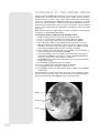
Point your telescope at the Moon (note that the Moon is not visible every night) and
practice using the Arrow keys, the digital front focus and the slew speeds to view different features. The Moon contains many interesting features, including craters, mountain ranges, and fault lines. The best time to view the Moon is during its crescent or
half phase. Sunlight strikes the Moon at an angle during these periods and adds a
depth to the view. No shadows are seen during a full Moon, making the overly bright
surface to appear flat and rather uninteresting. Consider the use of a neutral density
Moon filter when observing the Moon. See SERIES 4000 PHOTO-VISUAL FILTERS, page
48. Not only does it cut down the Moon's bright glare, but it also enhances contrast,
providing a more dramatic image.
Astronomical Observing
Used as an astronomical instrument, your telescope has many optical and electromechanical capabilities. It is in astronomical applications where the high level of optical performance is readily visible. The range of observable astronomical objects is limited only by the observer’s motivation.
To Track an Object Automatically
As the Earth rotates beneath the night sky, the stars appear to move from East to
West. The speed at which the stars move is called the sidereal rate. You can setup
your telescope to move at the sidereal rate so that it automatically tracks (follows) the
stars and other objects in the night sky. If the telescope is not tracking an astronomical object, the object will drift out of the eyepiece field of view. The tracking function
automatically keeps an object centered in the telescope’s eyepiece.
To automatically track objects, you need to learn how the Autostar II keypad operates
in order to move through its menus. You'll need to initialize and align your telescope.
Moving Through Autostar II’s Menus
The Autostar II database is organized in levels for quick and easy navigation.
Tip:
When multiple choices are
available within an Autostar
II menu option, the current
option is usually displayed
first and highlighted by a
right pointing arrow (>).
Note:
Press any key on the
Autostar II handbox to abort
the GPS fix. If aborted,
Autostar II then displays
"Enter Date." You may follow
prompts to perform a manual alt/az alignment (see
page 42) or press MODE
repeatedly until "Select
Item" displays to use the
Autostar II menu options.
22
J
Press ENTER (2, Fig. 2) to go deeper into Autostar II's menu levels.
J
Press MODE (3, Fig. 2) to move back toward the top menu level.
J
Press the Scroll keys (7, Fig. 2) to move up and down through the options available for each level.
J
Press the Arrow keys (5, Fig. 2) to enter characters and digits. The Arrow keys are
also used to move the telescope.
J
Use the Number keys to enter digits.
Automatic Alignment Feature
Autostar II offers four methods of altazimuth (alt/az) alignment; this section describes
how to initialize and align your telescope using Automatic Alignment. (For a description of the other alt/az alignment methods, see pages 42 and 43. For information
about equatorial (polar) alignment, see APPENDIX A, page 57.)
To prepare your telescope for Automatic Alignment:
1. Tighten the R.A. and Dec. locks (13 and 17, Fig. 1a).
2.
Verify that Autostar II is properly connected to your telescope. See TO CONNECT
AUTOSTAR II, page 17.
3.
Flip the telescope power switch to the ON position.
The Autostar II screen is activated and a copyright message displays briefly, followed
by a short beep. Then Autostar II takes a few moments to start up the system.
Important Note:
Once the telescope is
aligned, only use the Arrow
keys to move the telescope. Once the telescope
has been aligned, do not
loosen the telescope locks
(13 and 17, Fig. 1a), or
move the base manually,
or alignment will be lost.
Important Note:
If the objects you have
chosen are not in the
eyepiece after after
alignment, it is also
recommended that you
CALIBRATE SENSORS.
This menu allows you to
improve your telescope's
pointing accuracy to alignment stars. It calibrates to
correct slight mechanical
misalignment due to
transport, vibration, or
aging. It is recommended
that calibration be
performed once on a new
telescope after the user
initially assembles it.
When this menu is
selected, the telescope
slews to Polaris. Autostar II
then prompts you to center
Polaris and to press
ENTER. Autostar II uses
the position of Polaris to
fine tune the position of
North and also detects
level for the base of the
telescope.
4.
Autostar II initializes the Smart Drive if "On" has been previously chosen from
both the R.A. and Dec. PEC menus in the "Setup: Telescope" menu (the very first
time the system is turned on, the Smart Drive feature will not be enabled). Once
"On" is chosen, Autostar remembers the setting until "Off" is chosen again. If "On"
has been selected, the R.A. and Dec. motors operate briefly and "Initializing:
Smart Drive" displays.
5.
A message displays that warns not to look at the Sun. At the end of this message,
press the key prompted by Autostar II to signify that the message has been read
and understood.
6.
"Automatic Alignment" displays. Press ENTER. The system now performs the following routines (press any Autostar II key to abort Automatic Alignment) :
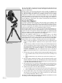
Caution: As the telescope performs the following operations, it will swing
and rotate. Keep a safe distance from the telescope.
a. Finds the home position. Moves the telescope to find the "home" position.
When the home position is found, the system knows the limiting positions of
the telescope and can avoid tangling cables and over-rotating the telescope.
b. Detects “level” of the base of the telescope; finds tilt and tip. To detect
level, Autostar II must calculate "level" at three compass points. See FINDING
TRUE LEVEL in the RCX400 INFO box on page 25.
Autostar II also determines the positioning (i.e., tilt and tip) of the optical tube.
c. Finds North. Locates magnetic North, then calculates true North. See
FINDING TRUE NORTH, page 25.
d. Attempts a "GPS Fix." The RCX400's GPS receiver attempts to acquire and
sync up with signals from GPS satellites. "Getting GPS Fix" displays. See THE
GLOBAL POSITIONING SYSTEM in the RCX400 INFO box on page 25.
After performing these operations, Autostar II now knows:
J The telescope's limiting positions
J Where level is for the telescope
J The location of true North
J The observing site's location
J The date and time
e. Star Alignment. Autostar II then chooses two stars to align upon.
"Searching...." displays. When the telescope slews (moves) to the first star for
alignment, it may not appear in the field of view in the eyepiece. If it is not, look
through the viewfinder—in most cases, the star will be visible. Use the Arrow
keys to move the telescope (you can change speed at which the telescope
moves: see SLEW SPEEDS, page 21 for more information) until the star is visible and centered in the eyepiece. The alignment star should be easily recognized and be the brightest star in the area of the sky where the telescope is
pointing. Press ENTER. Repeat this procedure for the second star. For more
information about alignment stars, see WHICH ONE'S THE ALIGNMENT STAR?
below.
RCX400 TIPS
Which One’s the Alignment Star?
If Autostar has chosen an alignment star with which you are unfamiliar, how can
you be sure if the star in your eyepiece is really the alignment star?
The rule of thumb is that an alignment star is usually the brightest star in that
area of the sky. If you perform a GO TO to an alignment star and you're not sure
if you have located the alignment star or it isn't in the eyepiece, look through your
viewfinder. When you view an alignment star in the viewfinder, it stands out dramatically from the rest of the stars in that portion of the sky. The viewfinder will
help you locate a star more quickly than the eyepiece, because it has a much
wider field of view than the eyepiece. Using Autostar, set the slew speed to 6 or
higher and use the Arrow keys to center the alignment star in the viewfinder. If
your viewfinder has been aligned with the telescope, the alignment star should
now be in the eyepiece. Set the slew speed to 4 or less and center the star in the
eyepiece.
23
Tip:
The GO TO key also
allows you to perform a
"spiral search." A spiral
search is useful when the
telescope slews to an
object, but that object is
not visible in the eyepiece
after the telescope finishes its search. (This sometimes occurs during an
alignment procedure.)
Press GO TO when the
telescope stops slewing.
The telescope begins to
move in a spiral pattern at
a very slow speed around
the search area. Look
through the eyepiece and
when the object does
become visible, press
MODE to stop the spiral
search. Then use the
Arrow keys to center the
object.
Important Note:
While performing the
automatic tracking procedure, only use the Arrow
keys to move the telescope. Once the telescope has been aligned,
do not loosen the telescope locks (13 and 17,
Fig. 1a), or move the
base manually, or alignment will be lost.
Tip:
To manually enter the
R.A. and Dec. coordinates of an object:
Press and hold MODE for
two seconds or more. The
R.A. and Dec. coordinates display. Press GO
TO. "Object Position" and
a set of coordinates displays. Then enter the R.A.
and Dec. coordinates of
any celestial object using
Number keys. As soon as
the coordinates are
entered, Autostar II slews
the telescope to the coordinates. Note that the telescope must be initialized for this procedure to
operate properly.
24
When the procedure is performed correctly, "Alignment Successful" displays.
If Autostar II does not display this message, perform this procedure again.
Note: Alignment stars may change from night to night. All that is required
is for the observer to center the selected stars in the eyepiece when
prompted.
Observe a Star using the Automatic Tracking Feature
Now that your telescope has been aligned, you are able to track celestial objects. In
this example, the Autostar II Arrow keys are used to find a star, and then Autostar II's
tracking capability automatically keeps the star centered in your telescope's eyepiece.
1. When Automatic Alignment is completed (as described in the previous section),
"Select Item: Object" displays on Autostar II.
2.
Select a bright star from one of the Object menus. You may choose any unobstructed, bright star for the purposes of this example. Use the viewfinder (21, Fig.
1a) to help line up on the star. Use Autostar II's Arrow keys to center the star in
the eyepiece. The tracking motors will then keep the star you have chosen in the
center of the eyepiece.
Go To Saturn
This exercise demonstrates how to select a celestial object, the planet Saturn, for
viewing from Autostar II’s Solar System library. Objects in the eyepiece should maintain their position even though the Earth is rotating beneath the stars. In other words,
the telescope tracks the chosen objects.
Note: Saturn is not visible the entire year; you may need to choose another object from any of Autostar II's many object libraries; however, the procedure, as described below, remains the same.
1
After the telescope is aligned, press Number key "5."
2.
“Solar System: Mercury” displays. Keep pressing the Scroll Down key until “Solar
System: Saturn” displays.
3.
Press ENTER. “Calculating” displays. Then “Saturn” and a set of coordinates displays. Note that Saturn’s (and other planets’) coordinates change throughout the
year.
4.
Press GO TO. “Saturn: Slewing...” displays and the telescope slews until it finds
Saturn.You may need to use the Arrow keys to center Saturn precisely in the eyepiece. Autostar II then automatically moves the telescope so that it "tracks"
Saturn (or whatever other object you may have chosen); i.e., Saturn remains centered in the eyepiece.
Using the Guided Tour
The Guided Tour feature is an easy and fun method of exploring Autostar II's GO TO
capabilities. This example demonstrates using “Tonight’s Best” Guided Tour.
1.
After observing Saturn, keep pressing MODE until “Select Item: Object” displays
again.
2.
Press the Scroll Down key twice. “Select Item: Guided Tour” displays.
3.
Press ENTER. “Guided Tour: Tonight’s Best” displays. Press ENTER.
Note: If you wish to try out other Guided Tours, press the Scroll Down key
to scroll through other tour choices. When the tour you wish to select displays, press ENTER.
4.
“Tonight’s Best: Searching...” displays. After calculating, “Tonight’s Best: Jupiter”
displays.
Note: Different objects may be displayed on a tour list on any given night.
Press ENTER to display information about the object. Press GO TO to move the
telescope to the object.
5.
Press MODE to return to the Tour list. Press the Scroll keys to scroll through the
list. Press ENTER when you find the next object you wish to observe.
6.
Press and hold down MODE for two seconds to leave the Guided Tour menu.
Other Guided Tours are available, such as "How Far is Far" and "A Star's Life." If you
have programming skills, you may wish to create a custom Guided Tour. See CREATE
YOUR OWN GUIDED TOUR, page 63.
RCX400 INFO
GPS
Receiver
The Global Positioning System
The Global Positioning System (GPS) is comprised of 24 satellites orbiting
the Earth that are constantly transmitting their precise position and time.
The system provides highly accurate, worldwide positioning and navigation
information for any number of applications.
GPS receivers on the Earth acquire signals from three to twelve satellites
to determine the precise latitude, longitude, and time of the receiver.
(Accuracy of the receiver's position may be within 10 to 15 feet.) As
Autostar II uses latitude, longitude, and time information to calculate the
positions of celestial objects, GPS is an ideal tool for aligning your RCX400
telescope.
Detecting True Level
Fig. 26: RCX400 GPS Receiver.
To detect level of the base of the telescope, Autostar II must calculate the tip
and tilt of the telescope at three compass points and then compensate for it.
Finding level involves the geometric calculations of a "plane." In order to
define a plane, three positions are necessary. This is not unlike building a
table: For a table to stand level and solid, it must have a minimum of three
legs. Autostar II makes gravitational measurements to make a precise determination of true level.
Finding True North
Locating True North is one of the most important ingredients in the alignment
of a telescope. True North is the axis—the pole—which the Earth spins about
and is a key reference for the motion of the Earth.
As you look at the night sky, the stars seem to move; in fact, if you watched
long enough or took a long time-exposure photograph, you'd realize that the
stars seem to revolve around one point—the pole or True North. When
Autostar II knows where True North is and also knows the time, it can calculate the location of all the other objects in the sky.
One traditional way to find True North is to locate the North Star, Polaris,
which lies very close to True North. Another way to calculate True North is to
use gyroscopes or accelerometers.
The RCX400 determines True North by using a magnetic North sensor. The
sensor locates magnetic North. Magnetic North is not True North, but a
measurement of the magnetic lines of the Earth. Magnetic North may deviate several degrees from True North. But Autostar II, using the observation
site location determined by the GPS and magnetic North information, can
calculate the position of True North.
Some areas are subject to magnetic disturbances, and the magnetic field of
the Earth changes slightly from year to year. Autostar II allows you to adjust
for discrepancies in the local magnetic field using the "Calibrate Sensors"
option in the Telescope menu. See page 34 for more information.
25
BASIC AUTOSTAR II
SETUP MENU
Automatic alignment
permits all telescope
operations with only
minimal setup.
Select Item:
Object
Select Item:
Setup
UTILITIES MENU
Calculate eyepiece
magnifications;
set timer alerts;
create your own
landmark survey.
AAutostar
utostar I I
The Universe o f
Select Item:
Utilities
GLOSSA RY
What is an elliptical galaxy?
How far away is the Sun?
Expand your knowledge of
astronomy by displaying terms
and definitions, and other information.
OBJECT MENU
Want to see Mars? The Orion nebula?
The Andromeda galaxy? Select from
over 180,000 objects and press
GO TO to move the telescope
automatically to an object.
Select Item:
Event
EVENT MENU
Display the time of
past, present, and future
astronomical events,
such as Moon phases
or meteor showers.
Select Item:
Guided Tour
Select Item:
Glossary
GUIDED TOUR
Autostar II escorts you
on a tour of tonight's
best celestial objects
at your viewing location.
Fig. 27: The Autostar II Universe: The six primary categories listed in the Select Item menu
of Autostar II.
Object
Event
Guided Tours
Glossary
Utilities
Setup
Fig. 28: Menus set in a loop.
It is important to understand that menu selections are set in a loop (Fig. 28). This means
that pressing the Scroll Down key (7, Fig. 2) cycles down through all the available
options within a given category, then returns to the first option. The Scroll Up key (7, Fig.
2) cycles up through the options in the opposite order. Note that this capability is a quick
way to get to an option that is near the bottom of the list. The following example demonstrates this capability.
Example:
To navigate to the “Select Item: Setup” menu option when the “Select Item: Object”
menu is displayed:
1.
Setup
Align
Date
Time
Daylight Saving
Telescope
Targets
etc.
Fig. 29: Menu options display on the
second line. Use the Scroll keys to
move up or down through the list of
options. Press ENTER to select the
desired option.
Press the Scroll Down key five times or the Scroll Up key once.
The screen in Fig. 29 displays two lines of information. The top line shows the current
menu. The second line displays an option which may be selected within that menu.
Some options are choices that select the next menu level down. The Scroll keys move
up and down within the list of available options, showing one option at a time.
When the desired option is displayed on the second line, press the ENTER key to
choose that option and move down one menu level.
Press the MODE key to leave a menu level; e.g., the wrong menu option is chosen.
Important Note: No matter how many levels into Autostar II are traveled,
each press of the MODE key moves up a level, until the top level, "Select
Item," is reached. Once in the Select Item level, press MODE to return to
the topmost level, "Select Item: Object."
Autostar II Navigation Exercise
To demonstrate how the Autostar II menu structure works, the following exercise calculates Sunset time so an evening observing session can be planned.
To Calculate Sunset time:
1. Press the MODE key several times, until “Select Item: Object” is displayed.
26
2.
Press the Scroll Down key once to display the “Event” option in the “Select Item”
menu.
3.
Press the ENTER key to choose the "Event" option and move down a level.
"Event: Sunrise" is displayed.
4.
Press the Scroll Down key once to display the "Sunset" option in the Event menu.
5.
Press the ENTER key to choose the "Sunset" option and move down another
level.
6.
Autostar II calculates the Sunset time based on the current date, time, and location. Autostar II then displays the results of the calculation.
7.
Press MODE once to start moving back up through the Autostar II levels. The first
level up is the Event menu.
8.
Press MODE again to move up another level. This is the top level, "Select Item."
9.
Press MODE again to return to the starting point of "Select Item: Object."
Example of Locating a menu
Display
MODE
ENTER
Arrow
keys
Scroll
Up
Scroll
Down
Fig. 30: Some of the features of the
Autostar II handbox.
As you typically will be using menus after you initialize and align your telescope, this example
will assume you have just completed aligning your scope. AutoStar II displays “Select Item:
Object” after the alignment procedure; this will be our starting point. In this example, we will
locate the “Owner Info” option. See Fig. 30 for the location of the Autostar II keys used in this
example.
1.
“Select Item: Object” displays.
2.
As the Owner Info option is in the Setup menu, you will have to use one of the Scroll keys
to navigate through the list of menus. Press the Scroll Down Key. “Select Item: Event” displays
3.
Keep pressing the Scroll Down key. Notice that all the menus display as you press the key:
Guided Tour, Glossary, Utilities, Setup. Stop when “Select Item: Setup” displays. If you press
the Scroll Down key one more time, “Select Item: Object” will display again. This is because
the list of menus or options cycles through each choice over and over again when you press
one of the Scroll keys.
4.
With “Select Item: Setup” displayed, press ENTER. Pressing ENTER selects the menu or
option currently displayed.
5.
“Setup: Align” displays.
6.
Press the Scroll Down key again. “Select Item: Date” displays. Autostar II will now display
all the choices that are available with the Setup menu.
7.
Continue to press the Scroll Down key until “Setup: Owner Info” displays.
8.
Press ENTER. “Owner Info: Name” displays. Press ENTER again. “Name” displays, with the
second line blank. On this line you may enter your first and last name into Autostar II’s memory.
9.
Press the Up or Down Arrow key. Notice that a letter of the alphabet displays. Continue to
press one of the Arrow keys until the first letter of your name displays.
10. Use the Right Arrow key to move to the next position so you can choose the second letter
of your name. Continue to use the Arrow keys to enter your full name.
11. Press ENTER when you are finished. Your name is now entered into AutoStar II’s
memory.
12. “Owner Info: Name” displays again (if you wish, you can press the Scroll Down key—“Owner
Info: Address” will display and you can enter your address if you wish).
13. Press MODE and “Setup: Owner Info” displays. Press MODE again. “Select Item: Setup”
displays. MODE allows you to backup and exit through the menu structure.
Navigating Autostar II
Tip:
When multiple choices
are available within a
menu option, the current
option is usually displayed first and highlighted by a right pointing
arrow (>).
Autostar II's menus are organized for quick and easy navigation:
J
Press ENTER to go deeper into Autostar II's menu levels.
J
Press MODE to move back toward the top menu level.
J
Press Number key "1" to engage the Speed mode, and then press Number keys
1 through 9 to change speeds.
J
Press Number key "4" to access the Focus menu.
J
Press Number key "7" to access the Reticle menu.
J
Press the Scroll keys to move up and down through the options or lists.
J
Press the Arrow keys to move the cursor across the display.
J
Press the Help (?) key to access on-line help.
27
28
Sunrise
Sun Transit
Sunset
Moonrise
Moon Transit
Moonset
Moon Phases
Next Full Moon
Next New Moon
Next 1st Qtr
Next 3rd Qtr
Meteor Showers
Quadrantids
Lyrids
Etc.
Solar Eclipses
Lunar Eclipses
Min. of Algol
Autumn Equinox
Vernal Equinox
Winter Solstice
Summer Solstice
Select Item:
Event
Figure 31: The Complete Autostar II Menu Tree Structure.
OTA Fan
Dew Heater
OTA Temperature
Ambient Temp.
Timer
Set
Start & Stop
Alarm
Set
On & Off
Eyepiece Calc.
Field of View
Magnification
Suggest
Sun Warning
Brightness Adj.
Contrast Adj.
Panel Light
Aux Port Power
Beep
Temperature
Battery
Landmark Survey
Sleep Scope
Park Scope
Select Item:
Utilities
Key
1
2
3
4
5
6
7
8
9
Menu
Speed
Caldwell catalog (C)
Messier catalog (M)
Focus
Solar System (SS)
Star library
Reticle (RET)
Index catalog
New General catalog (NGC)
Hot Buttons
Press the following keys to display
the corresponding menu:
Accretion Disk
Etc.
B...
C...
Etc.
A...
Select Item:
Glossary
Moon
Overview
Landing Sites
Apollo 11
Etc.
Craters
Abbot
Etc.
Mountains
Mons Bradley
Etc.
Mare, Lakes
Lacus Aestatis
Etc.
Valley, Rills
Rima Agatharchid
Etc.
Tonight's Best
How Far is Far
Etc.
Tour Objects
Select Item:
Guided Tour
• Right Ascension and Declination coordinates
• Altitude and Azimuth coordinates
• Local Time and Local Sidereal Time (LST)
• Timer and Alarm Status
• Date
• Site coordinates
• Battery status
Hold down MODE for two seconds and the
following data displays:
Solar System
Mercury
Etc.
Moon
Asteroids
Comets
Constellations
Andromeda
Etc.
Deep Sky
Named Object
Galaxies
Nebulae
Planetary Neb.
Etc.
Star
Named
SAO Catalog
Etc.
Satellite
Select
Add
Delete
Edit
User Objects
Select
Add
Delete
Edit
Landmarks
Select
Add
Delete
Identify
Browse
Start Search
Edit Parameters
Select Item:
Object
Align
Automatic
Easy
One Star
Two Star
Align on Home
Date
Time
Daylight Saving
GPS-UTC Offset
Smart Mount
Configuration
Off
On
Train
Update
Load
Save As
Delete
Erase
Telescope
Mount
Model
Focal Length
Max Slew Rate
Focuser
Calibrate
Collimate
Mount Upper Limit
Mount Lower Limit
Park Position
Calibrate Home
Anti-Backlash
Train Drive
Calibrate Sensors
Tracking Rate
Guiding Rate
Reverse L/R
Reverse Up/Dn
Home Sensors
GPS Alignment
R.A. PEC
Dec. PEC
High Precision
Targets
Astronomical
Terrestrial
Site
Select
Add
Delete
Edit
Owner Info
Clone
Download
Statistics
Reset
Select Item:
Setup
AUTOSTAR II's MENUS
Object Menu
Almost all observing with Autostar II is performed using the Object menu category.
(Note: Exceptions include Guided Tour and Landmark Survey.) See GO TO SATURN,
page 24, for an example of observing using the Object menu. Also see USING THE
GUIDED TOUR, page 24.
Autostar II contains many libraries of viewable objects, such as stars, planets, comets,
nebulae and so forth. When one of these objects is selected from a library, Autostar II
moves your telescope (if properly aligned) and points it at the selected object. Six of the
most popular libraries can be accessed directly using the hot buttons.
The Object Menu options include:
Solar System: A library of the eight planets (Earth is not included) in order out from
the Sun, followed by the Moon, asteroids, and comets.
Constellation: A library of all 88 Northern and Southern Hemisphere constellations.
When this menu option is chosen and a constellation name appears on the first line
of the screen, press GO TO once to change the second line to the name of the brightest star in the constellation. Press GO TO a second time to slew the telescope to that
star. Use the Scroll keys to cycle through the list of stars in the constellation, from
brightest to dimmest.
Deep Sky: A library of objects outside our Solar System such as nebulae, star clusters, galaxies, and quasars.
Star: A catalog of stars listed in different categories such as named, double, variable,
or nearby. Also included are the Hipparcos, SAO, HD, and HR catalogs. The Star catalog may also be accessed directly by pressing the Number key "6."
Want to learn more about
Observing Satellites? See
page 39.
Satellite: A library of Earth-orbiting objects such as the International Space Station,
the Hubble Space Telescope, Global Positioning System (GPS) satellites, and geosynchronous orbit satellites.
Other Catalogs are accessed directly using the Autostar II "hot keys": Caldwell (key
"2"), Messier catalog ("3"), Solar System ("5"), IC ("8"), and NGC ("9").
To slew the telescope to catalog objects:
Enter the catalog number of the object using the Number keys and then press ENTER.
For example: To slew to NGC 6720, press Number Key "9," then using the Number
keys, enter the digits "6-7-2-0." Then press ENTER.
Autostar II displays the common name and alternate names of the object, if available.
Press one of the Scroll keys to display some or all of the following information about
that object: Type of object (galaxy, nebula, etc.), Dec. and R.A. coordinates, constellation it is located within, magnitude, size, distance, and star-type classification, if the
object is a star. If further information is available, it displays as scrolling text.
Press GO TO. The telescope, if aligned (see AUTOMATIC ALIGNMENT, page 22), will
slew to that chosen object. Press MODE repeatedly to return to previous menu levels.
User Objects: Allows the user to define and store in memory deep-sky objects of specific interest that are not currently in the Autostar II libraries. See CREATING USER
OBJECTS, page 38, for more information.
Want to learn more about
Landmarks? See page 39.
Landmarks: Stores the location of terrestrial points of interest in the permanent
Autostar II database. This function works with a telescope that remains in one fixed
spot or can be setup in the exact same spot each time it is used.
J
Select: To select a Landmark already in the database (see ADD below), choose
the "Select" option and scroll through the list. Press ENTER to select a Landmark,
then press GO TO and the telescope slews to the object.
J
Add: To add a Landmark, choose the "Add" option. Enter a name for the
Landmark. Locate and center the Landmark in the eyepiece, then press ENTER.
Important Note: To add objects to the Landmark database, the telescope
must be located and aligned exactly as when the original objects were
added to the database.
29
Identify: An exciting feature for an observer who wants to scan the night sky and start
exploring. After the telescope has been properly aligned, use the Autostar II Arrow
keys to move about in the sky. Then follow this procedure:
Important Note: Only use the Arrow keys to move the telescope during
the Identify procedure. Do not loosen the telescope locks or move the
base or alignment is lost.
Want to learn more about
using the Browse menu?
See page 41.
1.
When a desired object is visible in the eyepiece, keep pressing MODE until the
“Select Item: Object” menu is displayed. Press ENTER to select this menu.
2.
Scroll through the Object menu options until the “Object: Identify” screen appears.
3.
Press ENTER. Autostar II searches the libraries for the identity of the object being
observed.
4.
If the telescope is not directly on an Autostar II library object, the nearest library
object is located and displayed on the screen. Press GO TO and the telescope
slews to that object.
Browse: Allows you to search the library for objects with certain parameters, much
like a search engine. "Edit Parameters" lets you set various parameters for the search,
such as: Object Type, Minimum Elevation, Largest, etc. Once you have set the parameters of the search, select "Start Search" and press ENTER. Autostar II will display the
results of the search.
Event Menu
The Event menu provides access to dates and times of astronomical events. The
Event database includes:
Sunrise, Sun Transit, and Sunset: Calculate the time of Sun rise, Sun transit, or Sun
set on the current date. Find rise and set times for other dates by entering a new date
into the “Setup: Date” menu.
Definition:
Transit is the time when
the Sun, Moon, or other
celestial object crosses an
observer's meridian, i.e.,
the time when an object is
at its highest point in the
sky on any given date.
Moonrise, Moon Transit, and Moonset: Calculate the time of Moon rise, Moon transit, or Moon set on the current date. Find rise and set times for other dates by entering a new date into the “Setup: Date” menu.
Moon Phases: Displays the date and time of the next Full, New, 1st Quarter, and 3rd
Quarter Moon.
Meteor Showers: Provides information on upcoming meteor showers, such as the
Perseids, the Leonids, etc. Also lists the dates of the showers and when they reach
maximum.
Note: Meteors are fast moving objects that cover large areas of the sky and
are usually best observed with the naked eye.
WARNING!
Never use
your Meade®
RCX400
Telescope to look at the
Sun! Looking at or near
the Sun will cause instant
and irreversible damage
to your eye. Eye damage
is often painless, so there
is no warning to the
observer that damage has
occurred until it is too
late. Do not point the telescope or its viewfinder at
or near the Sun. Do not
look through the telescope or its viewfinder as
it is moving. Children
should always have adult
supervision while observing.
30
Solar Eclipse: Lists upcoming Solar Eclipses, including the date and type (total,
annular, or partial) of eclipse. Use the Scroll Up and Down keys to display the available data. Remember, never use a telescope to look at the Sun! See WARNING! to the
left.
Lunar Eclipse: Lists upcoming Lunar Eclipses, including the date and type (total, partial, penumbral) of eclipse. Use the Scroll Up and Down keys to display the available data.
Min. (Minimum) of Algol: Displays the minimum brightness of the dramatic eclipsing
binary star system, Algol. It is relatively close at a distance of 100 light years. Every
2.8 days during a 10-hour period, Algol undergoes a major change in apparent magnitude as one of the two stars passes behind the other. The combined magnitude of
the two stars thus dips from +2.1 to a minimum of +3.4 halfway through the eclipse as
the second star is hidden. Autostar II calculates minimum magnitude time at mideclipse.
Autumn and Vernal Equinox: Calculate the time and date of the fall or spring equinox of the current year.
Winter and Summer Solstice: Calculate the time and date of the winter or summer
solstice of the current year.
Glossary Menu
The Glossary menu provides an alphabetical listing of definitions and descriptions for
common astronomical terms and Autostar II functions. Access directly through the
Glossary menu or through hypertext words embedded in Autostar II. A hypertext word
is any word in [brackets], usually found when using the Autostar II Help function or
when reading a scrolling message such as a description of a planet or star. Press
ENTER whenever a hypertext word is on screen and Autostar II goes to the glossary
entry for that word.
To access directly from within the Glossary menu, use the Scroll keys to scroll through
the alphabet. Press ENTER on the desired letter. Scroll to the desired entry and then
press ENTER to read the description.
Utilities Menu
The Utilities menu provides access to several extra features within Autostar II, including a countdown timer and an alarm. The Utilities functions include:
OTA Fan: Allows you to turn the fan off or on. The fan assists with the stabilization of
the optics. The fan should be activated at the beginning of an observing session and
run until the optics have achieved an equilibrium with the environment. Fan operation
time should range from about 5 to 25 minutes. Note that the fan may introduce a slight
vibration and this may cause noticeable movement observed with sensitive optics.
Dew Heater: Allow you to adjust heater level, setting from 0 to 100.
OTA Temperature: Provides a temperature reading at the edge of the corrector plate.
Ambient Temperature: Provides a temperature reading at the fork arm.
Timer: Selects a countdown timer. This feature is useful for functions such as
astrophotography and tracking satellites. To use the Timer, press ENTER, then
choose “Set” or “Start/Stop."
J
Set: Enter the time to be counted down, in hours, minutes, and seconds, then press
ENTER.
J
Start/Stop: Activates the timer set previously. Use the Scroll keys to toggle between
ON and OFF. When ON is displayed, press ENTER to activate the timer. When the
timer runs out, four beeps sound and the timer is deactivated.
Alarm: Selects a time for an alarm signal to sound as a reminder. To use the Alarm,
press ENTER, then choose "Set" or "Start/Stop."
Tip:
The Contrast Adjustment
feature is usually only
required in very cold
weather.
If you adjust the contrast so
that you can no longer
read the display, turn off
the power and turn it on
again. When Version
appears on the display (the
initial display screens are
not affected by the
Contrast control), press
MODE.
J
Set: Enter the time of day for the alarm to sound, in hours, minutes, and seconds,
then press ENTER.
J
Start/Stop: Activates the alarm set previously. Use the Scroll keys to toggle
between ON and OFF. When ON is displayed, press ENTER to activate the
alarm. When the alarm time arrives, Autostar II beeps. Press ENTER to deactivate the alarm.
Eyepiece Calc: Calculates information about an eyepiece for the specific telescope
to which Autostar II is connected.
J
Field of View: Scroll through a list of available eyepieces. When an eyepiece is
selected, the field of view is calculated.
J
Magnification: Scroll through a list of available eyepieces. When an eyepiece is
selected, the magnification is calculated.
J
Suggest: Autostar II calculates and suggests the best eyepiece for viewing,
based on the telescope and the object being viewed.
Sun Warning: Enables or disables Autostar II’s Sun warning display.
Brightness Adj: Adjusts the brightness of the display using the Scroll keys. When complete, press ENTER.
Contrast Adj: Adjusts the contrast of the display using the Scroll keys. When complete,
press ENTER.
31
Panel Light: Allows you to turn off LED panel light.
Aux Port Power: Allows you turn off and on the 12vDC OUT power port.
Beep: Turns the beep alerts on or off.
Temperature: Gives a temperature reading of the ambient air. This reading is not always
available.
Want to learn more about
Landmarks? See page 39.
Landmark Survey: Automatically slews the telescope to all user-defined landmarks
with a short pause at each location. Press ENTER to start the survey. While a slew is
in progress, press any key to skip that object and go to the next landmark on the list.
To observe a landmark for a longer period, press MODE when paused on the object
to stop the survey. Press ENTER to restart the survey at the first object on the list.
Sleep Scope: A power saving option that shuts down Autostar II and the telescope
without forgetting its alignment. With "Sleep Scope" selected, press ENTER to activate
the Sleep function. Autostar II goes dark, but the internal clock keeps running. Press
any key, except ENTER, to re-activate Autostar II and the telescope.
Park Scope: Designed for a telescope that is not moved between observing sessions.
Align the telescope one time, then use this function to park the telescope. The next
time it is powered up, pressing ENTER causes the telescope to move to its predetermined Park position. Once parked, the screen prompts to turn off power.
Important Note: When the "Park Scope" option is chosen and the display
prompts you to turn off the telescope's power, Autostar II is unable to be
returned to operation without turning the power off and then back on.
Setup Menu
There are numerous other features available within the Setup menu, including:
Align on Home: For permanently mounted telescopes only. If Calibrate Home has
been performed, power up your telescope and select this menu to return the previously calibrated home position. In other words, the telescope is fully aligned according to the setting that were stored in Autostar II's memory during the Calibrate Home
procedure. See CALIBRATE HOME, page 33, for more information.
Date: Changes the date used by Autostar II. This function is useful to check events in
the past or future. For example: Set the Date menu for a day three months in the
future. Then check the "Select Item: Event" menu for the Sunset time on that date. See
EVENT MENU, page 30.
Time: Changes the time entered into Autostar II. Setting the correct time is critical for
Autostar II to properly calculate locations and events. Time may be set to "AM," "PM,"
or 24-hour mode (military time). To select the 24-hour mode, press ENTER when the
the "blank" option displays (i.e., neither "AM" nor "PM" is displayed).
Daylight Saving: Enables or disables the Daylight Savings time setting.
Note: Daylight Savings Time may be referred to by different names in various areas of the world. Check local time to verify.
RCX400 TIPS
Look into the Future
The Autostar II Date option in the Setup menu is much more than just an entry
of today's date; with it you can look far into the future or learn about past
events. Autostar II can calculate the date and times of future events and, except
for eclipses, past events as well (based on the current calendar system). E.g.,
a Sunrise on March 6, 2043 A.D. or the Vernal Equinox in 1776 A.D. To use this
feature, enter the desired date in the Setup menu or select an option in the
Event menu.
Autostar II, using the Event menu, can calculate dates and times for Sunrises,
Sunsets, Moonrises, Moonsets, Moonphases, Solar and Lunar Eclipses (for
the next 100 years), meteor showers, equinoxes and solstices, and the minimums of Algol.
One very practical use of the Event menu is to check the Sunset option to
determine when you can begin your astronomical observing session.
32
Smart Mount: See page 69 for detailed information.
GPS-UTC Offset: Universal Time (UTC) adds leap seconds to its time calculations,
GPS does not. The offset is the number of leap seconds added since the establishment of GPS.
Telescope: Accesses several options, including:
J
Mount: Set this option to "Alt/Az" if using alt/az alignment and to "Polar" if using
polar alignment. "Alt/Az" is the default value.
J
Model: Allows you to select the telescope model connected to Autostar II.
J
Focal Length: Displays the focal length of the selected telescope.
J
Max Slew Rate: Sets the upper limit for the slew rate. 8 degrees per second is
the fastest setting.
J
Focuser: Allows you to recalibrate your focuser. Normally, not used. Recalibrates
focuser and focuser backlash.
J
Collimate: Allows you use the Arrow keys to collimate the telescope. See pages
51 and 52 for more details.
J
Mount Upper Limit: Allows you enter a number from 0 to 90 that sets an upper
limit as to how far the optical tube can swing upward during a programmed slew.
(Note that it does not prevent you from performing a manual slew past this limit.)
This is useful when you have a camera or other peripheral attached to the telescope—you can prevent it from striking the telescope base. 90 (straight up) is the
maximum value that can be entered.
J
Mount Lower Limit: Allows you enter a number from 0 to 90 that sets a lower
limit as to how far the optical tube can swing downward during a programmed
slew. (Note that it does not prevent you from performing a manual slew past this
limit.) This is useful when you have a large optical tube (12" model) or have a
dewshield attached to the telescope—you can prevent it from striking the telescope base. -90 (straight down) is the maximum value that can be entered.
J
Park Position: For permanently mounted telescopes only. After aligning your telescope, select this menu and power down the telescope. The alignment settings—level, North, time, alignment stars—are stored in Autostar II's memory and
are remembered after you power off the telescope. When you power on the telescope, "Automatic Alignment" displays after the start up routine. Press MODE (do
not press ENTER). The telescope remembers its alignment and you can continue viewing or performing other operations without aligning the telescope again.
Park Position provides two options. Use Current Position uses the last position
set by the user. Use Default Position levels telescope and points it North.
J
Calibrate Home: For permanently mounted telescopes only. After aligning your
telescope, select this menu and the alignment settings—level, North, time, alignment stars—are stored in Autostar II's memory and are remembered after you
power off the telescope. You can enable Autostar II to retrieve and automatically
align your telescope using these settings the next time you power up by choosing the Align on Home menu. See ALIGN ON HOME, page 32, for more information. Note: This method is not as precise as PARK POSITION (see above).
J
Anti-Backlash: This option allows you to change the backlash along either the
R.A. and the Dec. axes by entering a number from 0% to 199%. This sets the backlash in the way the Arrow keys move the telescope along an axis. If you enter a
value near 199%, telescope responds more quickly as you hold down an Arrow
key. If you enter a value near 0%, it takes longer for the tube to respond as you
hold down an Arrow key. Experiment with this option: Try changing the values until
the motion of the telescope (while holding down an Arrow key) feels comfortable
to you.
J
Train Drive: All telescopes have a certain amount of "backlash" (looseness in the
interplay of gears). This menu allows you to compensate for the backlash in the
the Altitude and Azimuth motors—which helps locate objects with more precision.
33
J
North
Calibrate Sensors: This menu allows you to improve your telescope's pointing
accuracy to alignment stars. It calibrates to correct slight mechanical misalignment due to transport, vibration, or aging. It is recommended that calibration be
performed once on a new telescope after the user initially assembles it.
When this menu is selected, the telescope slews to Polaris. Autostar II then
prompts you to center Polaris and to press ENTER. Autostar II uses the position
of Polaris to fine tune the position of North and also detects level for the base of
the telescope.
J
Tracking Rate: Changes the speed at which the telescope tracks targets in the
sky.
a.
Dec.
Setting
Circle
b.
c.
Level
Base
Fig. 32: Alt/Az Home Position. Note
that the Control Panel should face
South, which is not depicted in the
above photograph.
Note: Custom Tracking Rate allows you to enter values from -999 (stands for
99.9%) to 999 (stand for +99.9%). The lower the number, the slower the rate; the
higher the number the faster the rate. If you enter -999, the telescope will move so
slow as to appear to be stopped. If you enter 999, the telescope will be moving at
approximately twice the tracking rate.
J
Guiding Rate: Allows you to change the base slew speed, 1x. Enter a percentage of the speed (less than 100%) and press ENTER. This function may be useful in guiding the telescope during CCD and long-exposure photography. See
SLEW SPEEDS, page 21, for more information.
J
Reverse L/R: Reverses the functions of the Left and Right Arrow keys for controlling the telescope's motion (i.e., the Right key moves the telescope to the left).
J
Reverse U/D: Reverses the functions of the Up and Down Arrow keys for controlling the telescope's motion (i.e., the Up key moves the telescope down).
J
Home Sensors: Turns off or on the True North and True Level sensors, if preferred, for Easy, One-Star, and Two-Star alignment. User must then manually level
the telescope, set Dec. circle to 0°, point the optical tube to True North and point
the control panel on the base to South during alignment. The default setting for
this menu is "On." See Figs. 32 and 33.
J
GPS Alignment: Allows three options. Select "Off" if you wish to align the telescope manually (turns off GPS). Select "On" (default setting) if you wish to automatically align your telescope and want the telescope to get the GPS fix when it
is needed during alignment. Select "At Start Up" if you want the telescope to get
a GPS fix when the telescope is powered up.
J
Dec. PEC: Allows you to perform periodic error correction on the Dec. drive worm
gear. Must be performed with a high-power reticle (eg., 9mm). You may restore
the factory default setting by selecting “On.”
J
R.A. PEC: Allows you to perform periodic error correction on the R.A. drive worm
gear. Must be performed with a high-power reticle (eg., 9mm). You may restore
the factory default setting by selecting “On.”
J
High Precision: If High Precision is turned on, when looking for a faint celestial
object (e.g., a nebula or galaxy), Autostar II first slews to a nearby bright star and
displays "ENTER to Sync." Center the star in the eyepiece, then press ENTER.
At that point the telescope has a high precision alignment to that part of the sky
and it then slews to the object that was originally requested.
Fig. 33: Dec. Setting Circle at 0°.
Do you want to learn how to
perform the periodic error
correction procedure?
See PERIODIC ERROR CORRECTION, page 44.
Tip:
If the "ENTER to Sync" feature is accessed by mistake
(holding the ENTER key for
more than 2 seconds),
press MODE to return to
the previous screen.
Want to learn more about
adding and editing sites?
See page 37.
34
Sidereal: The default setting for Autostar II; sidereal rate is the standard rate
at which stars move from East to West across the sky due to the rotation of
the Earth.
Lunar: Choose this option to properly track the Moon over long observing
sessions.
Custom: Allows entry of user-defined tracking rates.
Targets: Switches between Astronomical targets and Terrestrial targets. If
"Astronomical" is selected, the telescope tracking motor is activated and any object
you observe will remain centered in the eyepiece. If "Terrestrial" is selected, the tracking motor is turned off. See TO TRACK AN OBJECT AUTOMATICALLY, page 22.
Site: Site provides access to several options including:
J
Select: Displays the currently selected observing site. Use the Scroll keys to
cycle through all available sites (see ADD below). Press ENTER when the site
you wish to select displays. Use this option when you move to a different geographic location.
J
Add: Allows you to add new observing sites to the database. Scroll through the list
of Countries/States. Press ENTER when the site you wish to add displays. Then
choose the desired city in the same manner.
However, when the GPS signal is received, the site is normally selected automatically and the site list is updated automatically. Use of this option is not necessary
and is included for the convenience of those users who may wish to enter a site
manually. You may edit the name of a site using the Edit option (see below).
Time Zone
Atlantic
Eastern
Central
Mountain
Pacific
Alaska
Hawaii
Shift
-4 Hours
-5 Hours
-6 Hours
-7 Hours
-8 Hours
-9 Hours
-10 Hours
Table 1: Time Zone Shift.
Calculations are for standard
time.
J
Delete: Deletes a stored site from the database.
J
Edit: Edits a selected site, including: the name, latitude, longitude, and time zone.
Time Zone refers to the Greenwich Mean Time (GMT) time zone shift. Users
West of Greenwich, England use “-” hours, East of Greenwich use “+” hours. For
the United States, look up the time zone shift in Table 1.
Note: Autostar II compensates for daylight savings time, if selected. See
SETUP MENU: DAYLIGHT SAVING, page 32.
Owner Info: Accesses the owner information menu, including:
J
Name: Users may enter both their first and last names using the Up and Down
Arrow keys to cycle through the alphabet. Use the Right and Left Arrow keys to
move through the text. Press ENTER when the entry is complete.
J
Address: Use the Up and Down Arrow keys to enter your street address, city,
state, and zip code. Press ENTER when the entry is complete.
Clone: Uploads information from one Autostar II handbox to another. Three options
are available:
Note:
The Download function
requires the USB cable supplied with the RCX telescope. See page 43 for
more information on how to
download.
Important Note:
If your download fails in the
middle of the download
attempt (e.g., your PC
crashes), turn off the telescope. Turn the telescope
back on and as soon the
Autostar II display lights up,
press "999." Then attempt
the download again.
J
Catalogs: Sends only user-defined object information, such as new satellite
orbits or comet data to another Autostar II handbox.
J
Software: Sends only the basic Autostar II software. This is useful if one user has
downloaded a new version of Autostar II software from the Meade website
(www.meade.com) and wants to pass this software along to friends.
J
All: Everything—user-defined information and Autostar II software—is sent to
another Autostar II.
Download: Transfers information from another Autostar II. During the operation, the
warning “Downloading Do Not Turn Off” appears.
J
Catalogs: Receives only user-defined object information, such as new satellite
orbits or comet data to another Autostar II handbox.
J
Software: Receives only the basic Autostar II software. This is useful if one user
has downloaded a new version of Autostar II software from the Meade website
(www.meade.com) and wants to pass this software along to friends.
J
All: Everything—user-defined information and Autostar II software—is received
by another Autostar II handbox.
Statistics: Provides basic statistical data about Autostar II, including:
J
Characters Free: Displays how much room is available in user-defined object
memory.
J
Version: Displays the current version of the Autostar II software.
J
Serial Number: Displays the unit's serial number.
Reset: Completely resets Autostar II. Most values entered into the menus revert to
factory defaults. Autostar II requires initialization again after a Reset before proceeding with observations. See AUTOMATIC ALIGNMENT, page 22.
35
"Hot Button" Menus
Two menus, six object libraries and two functions can be accessed directly using the
Number keys (commonly referred to as "hot buttons"). The two functions, the Speed
mode and the Utility light are described earlier in the manual.
Focus Control Menus: Press Number key "4" to select these menus directly from
Autostar II's keypad. Each time you press Focus, the key toggles between focus/focus
speed menus and the preset control menus. When “Focuser: Fast” displays, press the
Up or Down Scroll keys to select a focus speed (fast, medium, slow or fine). When
“Focuser: Position” displays, use the Up or Down Arrow keys to achieve fine focus of
the object.
You can toggle the Focus key to display the “Focuser: Preset” menus. The Focuser preset menu allows you to assign nine focus positions. If you “park” the telescope, you can
set your own focus, focus for your observing partners and the focus for your camera
or imager. Other Preset menus allow you to select a focus you have assigned and also
to Sync on a Focus Preset. The Sync on a Focus Preset allows you retrieve focus positions when you do not park your telescope. See page 20 for more information. Also
see page 32 for information about parking your telescope.
Reticle Control Menu: Press Number key "7" to select this menu directly from
Autostar II's keypad. "Reticle Control: Set Intensity" displays. Press ENTER. The
Intensity menu allows you to change the intensity of the Reticle Eyepiece Illuminator.
Use the Scroll keys to change the value. As you change the value, look through the
reticle to note how the Intensity changes.
Note: You may continue to change the values using the Scroll keys (and thus
changing the intensity) until you press ENTER again. This allows you to
experiment with the intensity level until you decide which intensity level works
best for you. This feature operates in the same manner in the Rate and Duty
Cycle menus.
When you have finished adjusting the intensity, press ENTER. Press Number key "7"
again and the Rate menu displays. Press ENTER again. Use the Scroll keys to change
the value of the the rate at which the Reticle Eyepiece blinks. As you change the value,
look through the reticle to note how the Blink Rate changes.
When you have finished adjusting the rate, press ENTER. Next, Press Number key "7"
again and the Duty Cycle menu displays. Press ENTER again. The Duty Cycle menu
controls how long the Reticle Eyepiece Illuminator is on during a blink cycle. Use the
Scroll keys to change the value. As you change the value, look through the reticle to
note how the Duty Cycle changes. When you have decided on a Duty Cycle value,
press ENTER.
To exit the Reticle menu, press MODE once.
Object Catalogs: See page 29 for more information.
36
ADVANCED AUTOSTAR II FEATURES
Before trying out the examples in this section, familiarize yourself with the basic operations of Autostar II described earlier in this manual. The following examples assume
that you have a basic knowledge of Autostar II and understand how to scroll to a
desired menu or menu option, and how to enter numbers and text. It also assumes
that you have initialized and aligned your telescope.
Adding Observing Sites
If you plan to observe using Autostar II at different geographic locations, you can store
observation sites in Autostar II's memory to help simplify your telescope setup.
Perform these procedures using the Site options (Add, Select, Delete, Edit) of the
Setup menu.
To Add a Site to the user-defined site list:
Important Note:
The Site information is
stored in the Site menu. If
you move the telescope
more than 5 miles of your
initial observing location,
Autostar II automatically
determines your location
when it gets a GPS Fix,
and adds the new location
to the Site menu.
In this example, you will choose a city and add it to the database list. You will then
select the site to enable it.
1.
Navigate to the "Setup: Site" menu. Press ENTER,
2.
Scroll through the options until "Site: Add" displays. Press ENTER.
3.
Scroll through the list of countries/states. Press ENTER when the country/state
you wish to add displays.
4.
Scroll through the list of cities. Press ENTER when the city you wish to add displays. The Site is now added to the database. You may add sites using this
method.
5.
To choose a site, navigate to "Setup: Select." Press ENTER. Scroll through the
list of sites. When the desired site displays, press ENTER.
To Edit a Site:
In this procedure, you will enter a location that is not available in the Autostar II database by editing data of a nearby site. You will edit the location's name, latitude, longitude, and the time zone shift. You will then select the site to enable it.
You will need to know the latitude and longitude of your location to perform this procedure.
1.
Using the Add option, choose a site on the list that is closest to your observing
site and press ENTER so that the site is added to your observing sites list.
Choosing a site already on the list (as opposed to using the "Custom" feature)
makes it easier to edit, as the "Time Zone" value may not need to be changed.
2.
Scroll to "Site: Edit" and press ENTER. "Edit: Name" displays. Press ENTER.
3.
The name of the site you have just entered to your list displays; if it does not,
scroll to the site.
4.
Using the Arrow keys, change the name of the site so that it now reads the name
of your observing location. Press ENTER. "Edit: Name" displays again.
5.
Press the Scroll Down key and "Edit: Latitude" displays. Press ENTER.
6.
Using the Number Keys, enter the latitude of your observing site and then press
ENTER. "Edit: Latitude" displays again.
7.
Press the Scroll Down key and "Edit: Longitude" displays. Press ENTER.
8.
Using the Number Keys, enter the longitude of your observing site and then press
ENTER. "Edit: Longitude" displays again.
9.
Press the Scroll Down key and "Edit: Time Zone" displays. Press ENTER. (If the
site you chose from the list in step 1 has the same Time Zone as the site you are
editing, just press ENTER again to go on to the next step.) "Time Zone" refers to
the Greenwich Time Zone shift. Users West of Greenwich, use "-" hours (one hour
per time zone) and users East of Greenwich use "+" hours. For the United States,
look up the shift in TABLE 1, page 35.
10. After entering the shift, press ENTER. "Edit Time Zone" displays.
37
11. Press MODE. "Site: Edit" displays.
12. Using the Arrow keys, scroll to "Site: Select." The site you have just edited displays. Press ENTER to select the site.
Creating User Objects
In this procedure, you will enter coordinates of celestial objects that do not appear in
any of the Autostar II libraries.You will enter the object's name and R.A. and Dec. coordinates (required information). You may also enter the object's magnitude and size
(optional information).
Although Autostar II contains an extensive database of celestial objects (stars, nebulae, planets, etc.) that you can observe, you may eventually want to view objects that
are not part of a library. Autostar II provides a feature that allows you to enter an
object's R.A and Dec. coordinates in the "User: Objects" option of the Object menu
and allows automatic slewing of the telescope to the user-entered coordinates.
In order to use this menu option, you first need to look up the R.A and Dec. coordinates of the object or objects you wish to observe. Check your local library, computer
store, or bookstore for astronomy books, CD Roms, or magazines (such as Sky &
Telescope or Astronomy), to find coordinates of celestial objects. The objects/coordinates you enter become part of your own permanent database, called "User Objects."
To enter coordinates of an object into the "User: Objects" option of the Object
menu:
Tip:
Using Autostar II to find
objects not in the libraries:
If you do not wish to navigate
through the menus, a more
direct way to enter coordinates is to press and hold
MODE for two seconds or
more. R.A. and Dec. coordinates display. Press GO TO.
"Object Position" and a set of
coordinates displays. Enter
the R.A. and Dec. coordinates
of any celestial object using
Number keys, overwriting the
coordinates currently displayed. As soon as the coordinates are entered, Autostar
II slews the telescope to the
coordinates. Note that the
telescope must be aligned
(see page 22).
However, if you wish to store
the coordinates of an object
in memory, use the method
described at the right.
1.
Make sure Autostar II has been initialized and the telescope has been aligned.
2.
After the telescope is aligned, "Select Item: Object" displays. (If necessary, use
the Scroll keys to scroll through the menus, as previously described, to find this
option.) Press ENTER.
3.
"Object: Solar System" displays. Keep pressing the Scroll Up key until "Object:
User Object" displays and press ENTER.
4.
"User Object: Select" displays. Press the Scroll Down key once. "User Object:
Add" displays. Press ENTER.
5.
"Name" displays on the top line and a blinking cursor on the second line. Use the
Arrow keys, as previously described, to enter the name of the object you wish to
add to the database. When you are finished, press ENTER.
6.
"Right Asc.: 00.00.0" displays. Use the Number keys to enter the digits for the
Right Ascension coordinate of your object. When you are finished, press ENTER.
7.
"Declination: +00°.00'" displays. Use the Number keys to enter the digits for the
Declination coordinate of your object. If necessary, use the Scroll Keys to change
"+" to "-." When you are finished, press ENTER.
8.
Autostar II then prompts you to enter the size of the object. This step is optional.
Use the Number keys to enter the size (in arc-minutes), if so desired, and press
ENTER to go to the next display. If you do not wish to enter this information, simply press ENTER.
9.
Autostar II then prompts you to enter the magnitude of the object. This step is also
optional. Use the Number keys to enter this information, if so desired, and press
ENTER to go to the next display. "User Object: Add" displays again.
To GO TO a user-entered object:
In this procedure, you will choose an object from the User Object list and GO TO the
object.
38
1.
With "User Object: Add" displayed, press the Scroll Up key once. "User Object:
Select" displays. Press ENTER.
2.
Use the Scroll keys (if necessary) to scroll to the desired object. Press ENTER.
3.
The name of the object and the Right Ascension and Declination coordinates display.
4.
Press GO TO and the telescope slews to the object.
Observing Satellites
In this procedure, you will prepare your telescope to observe a satellite pass.
1. Navigate to the "Object: Satellite" menu option and press ENTER.
2. Use the Scroll keys to scroll through the list of satellites.
3. Select a satellite from the list and press ENTER.
4. "Calculating...." and then "Tracking..." displays. If the satellite is going to make a
pass, "Located" displays.
5. Use the Scroll keys to display data about the pass: aos—acquisition of signal and
los—loss of signal. If you subtract the aos from the los, you can calculate how
long the satellite will be visible. Location information also displays.
6. "Alarm" displays after the location information. Press ENTER and Autostar II
automatically sets the alarm to sound a minute before the satellite's scheduled
appearance. You may return to regular observations until the alarm goes off.
7. When the alarm goes off, return to the Satellite menu and press a Scroll key until
the desired satellite is on the top line of the display.
8. Press GO TO. Autostar II slews the telescope to where the satellite should
appear. The motor drive stops and a countdown is displayed.
NOTE: If the scheduled appearance position of the satellite is obstructed
(i.e., by a building, tree, or hill), press ENTER and Autostar II starts to
move the telescope along the expected satellite track. When the track
clears the obstruction, press ENTER again to pause the telescope, then
continue with this procedure.
9. With about 20 seconds left on the countdown timer, start watching through the
telescope viewfinder for the satellite to enter the field of view.
10. When the satellite enters the viewfinder field of view, press ENTER. The telescope starts to track with the satellite.
11. Use the Autostar II Arrow keys to center the object in the viewfinder, then look
through the eyepiece to view the object.
Satellite orbits change and new satellites (including the Space Shuttle) are launched.
Visit the Meade website (www.meade.com) approximately once a month to get
updated information and instructions on how to download this data to Autostar II. If
orbital parameters are more than one month old, the satellite pass may not happen at
the time predicted by Autostar II. Downloading requires the USB cable supplied with
your telescope.
Note: Satellite observing is an exciting challenge. Most satellites are in
low orbit, travelling at approximately 17,500 mph. When visible, they move
quickly across the sky and are only in the field of view for a few minutes,
requiring Autostar II to slew the telescope rapidly. Best viewing is near
Sunrise or Sunset when the sky is still dark. Viewing in the middle of the
night can be problematic because a satellite may pass overhead, but not
be visible as it is in the Earth's shadow.
Tips:
To use the Landmark function, the telescope must be
located and aligned exactly
as when the landmark(s)
was added to the database.
To add objects to the
Landmark database, the telescope must be located and
aligned exactly as when the
original objects were added
to the database.
Landmarks
This menu option allows you to define and store terrestrial objects in the Landmark
database. First, a landmark needs to be stored in memory using the "Landmark: Add"
option. To view a landmark, use the "Landmark: Select" option. Landmarks may also
be viewed using the "Landmark Survey" option in the Utilities menu.
To Add a landmark to the database:
In this procedure, you will store the location of terrestrial landmarks in Autostar II's
memory.
1. Note for future reference where the telescope is located and if you have aligned the
telescope, which alignment method is used.
2.
Display the "Setup: Targets" menu option. Chose "Terrestrial" and press ENTER.
"Setup: Targets" displays again. Choosing this option turns off tracking for astronomical objects which is not useful for the viewing of terrestrial objects such as
39
those in the Landmark database. Be sure to change this option back to
"Astronomical" when you wish to view celestial objects again.
3.
Press MODE once. "Select Item: Setup" displays.
4.
Press the Scroll Down key once and "Select Item: Object" displays. Press
ENTER. "Object: Solar System" displays.
5.
Press the Scroll Up key twice and "Object: Landmarks" displays. Press ENTER.
"Landmark: Select" displays.
6.
Press the Scroll Down key once. "Landmark: Add" displays. Press ENTER.
7.
"Landmark Name" displays. Using Arrow keys, enter a name for the landmark you
wish to add to the database. When finished, press ENTER.
8.
"Center Landmark. Press Enter" displays. Using only the Arrow keys (do not manually move the telescope), move the telescope to the desired landmark and center the object in the eyepiece. Press ENTER. The object is now stored in memory.
9.
"Landmark: Add" displays. If you wish to add more landmarks, repeat steps 5
through 8.
To Select a landmark from the database:
1. Make sure the telescope is located and aligned exactly as when the desired landmark was entered into memory.
2.
Display the "Landmark: Select" menu option. Press ENTER.
3.
Use the Scroll keys to scroll through the list of objects you have previously
entered. When the desired object displays, press ENTER to select the object.
Use the Scroll keys to scroll through location information about the object, if
desired. Press GO TO to slew the telescope to the landmark.
4.
Press MODE to exit.
To perform a Landmark Survey:
This procedure allows you to perform a tour of the objects entered in the "Object:
Landmark" menu option—note that the Landmark Survey will function only if you have
previously entered objects in the Landmark menu.
1. Navigate to "Utilities: Landmark Survey" menu and press ENTER.
2.
"Landmark Survey: Slewing..." displays. The telescope moves to the first object
on the Survey list and displays the name of the object.
3.
Press MODE to stop the Survey. Press ENTER to restart the survey at the first
object of the survey.
To check on the available amount of memory in Autostar II:
Autostar II has a limited amount of memory. Once you begin to store Landmarks, user
objects and other bits of information in Autostar II, you will begin to use up memory.
This procedure allows you to check on how much memory is still available.
1.
Navigate to the "Setup: Statistics" menu option and press ENTER.
2.
"Statistics: 37.2K Char. Free" displays. This is the amount of memory that is still
available to the user.
Identify
This procedure allows you to use Autostar II to identify objects you have found in the
night sky using the Arrow keys. If the object is not in Autostar II's database, Autostar
II displays information about an object in its database that is closest to the one you
queried about.
Important Note: For this function to operate properly, you must first initialize and align Autostar II. If you physically move the telescope after initialization, this function will fail to operate properly.
40
In this procedure, you will center an object you wish to have identified by Autostar II in
the telescope eyepiece and use the "Identify" menu to find out information about the
object or the nearest object to it in the Autostar II database.
1.
Center the object you wish to have identified in the telescope's eyepiece.
2.
Navigate to the "Object: Identify" option and press ENTER.
3.
"Searching..." displays. When Autostar II finishes calculating, the name of the
closest object displays.
4.
Press a Scroll key to display information about this object. Autostar II displays
some or all of the following information about the object with each press of a
Scroll key:
Displayed information:
Catalog or common name of object
Type of object
Right Ascension
Declination
Constellation
Magnitude
Size
Scrolling message
Example:
Messier 107, NGC6171, Orion Nebula, etc
Globular Cluster, Nebula, Black Hole, etc.
16:32:4
13°03'
Virgo, Orion, etc.
3
2'
"This Globular Cluster is 10,000 light years
away...."
Browse
This menu allows you to search the libraries for objects with certain parameters, much
like a search engine. "Edit Parameters" lets you set various parameters for the search,
and "Start Search" activates the search. A typical search might be performed as follows:
1.
Select "Browse" from the Object menu. Press ENTER. "Browse: Start Search"
displays.
2.
Press one of the Scroll Keys and "Browse: Edit Parameters" displays. Press
ENTER.
3.
"Edit Parameters: Largest (mins)" displays. "Mins" stands for arc-minutes. Press
ENTER.
4.
"Largest (mins)" and a value displays. Using the Number keys, enter a size in arcminutes. Autostar II will search for objects up to this size and no larger. Press
ENTER.
5.
"Edit Parameters: Largest (mins)" displays again. Press the Scroll Down key. "Edit
Parameters: Smallest (mins)" displays. Enter the value for the smallest size of an
object that Autostar II will search for in the database. Continue with "Brightest,"
Faintest," and "Minimum Elevation," using the procedure described in steps 3 and
4.
6.
After "Minimum Elevation," "Object Type" displays. Press ENTER." "+Black Hole"
displays. If you do not wish to have "Black Holes" in your search, press ENTER
and the "+" changes to a "–." Press the Scroll Down key to scroll to the next item.
"+Diffuse Nebula" displays. Continue to scroll through the list and press ENTER
if you wish to change the "+" to a "–" or vice-versa.
7.
After you have scrolled to the last item on the "Object Type" list, press MODE
twice and the Scroll Down key once. "Browse: Start Search" displays. Press
ENTER. "Start Search: Next" displays. Press ENTER. Autostar II searches the
database and displays the first object that matches the search parameters you
have entered. Use the scroll keys to display information about the object. Press
MODE and "Start Search: Next" displays again. Press ENTER and the next item
matching the parameters displays. Repeat this procedure to display all the
objects. Press GO TO to slew telescope to a displayed object.
8.
Press MODE repeatedly to leave this menu.
41
Alternate Alt/Az Alignments
If you would rather set up your telescope without using automatic alignment, Autostar
II offers alternative alignment methods for both alt/az and equatorial mounting. During
the One-Star and Two-Star alt/az alignment procedures, you will (unlike the Automatic
and Easy alignment procedures) manually place the telescope in the home position.
The procedures for equatorial (polar) alignment are discussed in APPENDIX A, page
57; the three alternative alt/az alignment methods are discussed below.
Important Note:
If you disable the automatic
alignment/GPS function and
then use the alternate alignments described in this section, you will be prompted to
enter the Time, Date, and
Daylight Savings status.
Initialize Autostar II
First, you need to initialize Autostar II.
1. Tighten the R.A. and Dec. locks (13 and 17, Fig. 1a) to a firm feel.
2. Verify that Autostar II is properly connected to your telescope. See TO CONNECT
AUTOSTAR II, page 17.
3. Flip the telescope power switch to the ON position.
The Autostar II screen is activated and a copyright message displays briefly, followed
by a short beep. Autostar II takes a few moments to start up the system.
4. A message then displays that warns not to look at the Sun. At the end of this message, press the key prompted by Autostar II to signify that the message has been
read and understood.
6. Autostar II displays "Align: Automatic."
You are now ready to align your telescope using one of the three alt/az alignment procedures.
Easy (Two-Star) Alignment
In this method, Autostar II automatically picks two stars from its libraries for alignment.
During the procedure, Autostar II slews the telescope to a first alignment star. The user
is asked to verify that the telescope is pointed at the chosen star and then prompted
to center the star in the eyepiece. The process is repeated with a second star to complete the alignment.
Note: Before performing this procedure, first verify that INITIALIZE
AUTOSTAR II, above, has been performed.
How to perform the Easy Align Procedure
1. Alignment Option Screen. Following initialization, "Align: Automatic" displays.
2.
Select Alignment. Press the Scroll keys until "Align: Easy" displays. Press
ENTER.
3.
Home Position. The telescope automatically sets the following positions: home,
level, North, and True North. You may turn off the sensors and manually set these
positions. See HOME SENSORS, page 34 for more information.
4 . Star Alignment. Autostar II chooses two stars to align upon. The telescope slews
to the first star for alignment. Should the alignment star not appear in the field of
view in the eyepiece, it should be easily recognized: It will be the brightest star in
the area of the sky where the telescope is pointing. Use the Arrow keys to move
the telescope until the star is visible and centered in the eyepiece. Press ENTER.
Repeat the procedure for the second alignment star.
Note: See WHICH ONE'S THE ALIGNMENT STAR, page 23, for some important tips concerning alignments stars and using your viewfinder.
When the procedure is performed correctly, "Alignment Successful" displays. If
Autostar II does not display this message, perform this procedure again. (Keep
pressing MODE until "Align: Easy" displays and repeat the procedure.)
Two-Star Alt/Az Alignment
42
Two-Star Alignment requires some knowledge of the night sky. Autostar II provides a
library of bright stars and two stars from this library are chosen by the observer for
alignment. In this procedure, Autostar II does not automatically find home, level, or
North.
1. Alignment Option Screen. "Align: Automatic" displays.
2. Select Alignment. Press the Scroll keys until "Align: Two Star" displays. Press
ENTER.
3.
Set Home Position. Place the telescope in the home position.
To Set the Home Position Manually:
a. See Figs. 32 and 33, page 34. Loosen the telescope’s Dec. lock (17, Fig.
1a). Set the optical tube to 0° on the Dec. setting circle (Fig. 33).
b. Tighten the Dec. lock (17, Fig. 1a) to a firm feel only.
Note:
Autostar II locates alignment stars based on the
date, time, and location
entered. The alignment
stars may change from
night to night. All that is
required is for the observer
to center the selected stars
in the eyepiece when
prompted.
Tip:
Try a Spiral Search
The GO TO key also allows
you to perform a "spiral
search." A spiral search is
useful when the telescope
slews to an object, but that
object is not visible in the
eyepiece after the telescope finishes its search.
(This sometimes occurs
during an alignment procedure.) Press GO TO when
the slew is finished and the
telescope starts slewing in
a spiral pattern at a very
slow speed around the
search area. Look through
the eyepiece and when the
object does become visible,
press MODE to stop the
spiral search. Then use the
Arrow keys to center the
object.
c. Level the tripod base.
d. Move the base of the telescope so that the computer control panel (12, Fig.
1a) approximately faces South.
e. Unlock the R.A. lock (13, Fig. 1a) and turn the telescope's optical tube horizontally until it points North.
f. Re-lock the R.A. lock (13, Fig. 1a). Press ENTER.
g. Press ENTER.
4 . Star Alignment. "Select Star" displays. Autostar II then displays a library of stars
for the observer to choose from. Use the Scroll keys to scroll to a star on the list
that you wish to align upon. Select a star that you can easily locate in the night
sky. Press ENTER.
5.
Center Star. The telescope slews to the star. Use the Arrow keys to move the telescope until the star is centered in the eyepiece. Press ENTER.
6.
Center Star. Repeat procedure for the second alignment star. The telescope is
aligned and you are now ready to use Autostar II's GO TO capabilities for a night
of observing.
One-Star Alt/Az Alignment
One-Star Alignment requires some knowledge of the night sky. Autostar II provides a
library of bright stars. One-Star Alignment is identical to Two-Star Alt/Az: Alignment
(see TWO-STAR ALT/AZ ALIGNMENT, page 42), except only one star from the database is chosen by the observer for alignment.
To Download the Latest Version of Autostar II Software
Included with your telescope is a CD ROM and a USB cable. You need to install the
USB drivers, that are included on the CD ROM, BEFORE plugging in the cable:
1
Select RCX Users (the fourth selection on the list) from the CD Rom.
2
Follow on screen instructions (click “Next” and “Finish” buttons when asked to
do so).
3
Plug in the USB cable. Plug one end into one of the RCX400 USB ports on a
computer control panel/ Plug the other end into a USB port of your PC.
Next, you will install the Autostar Suite software from the CD ROM. This software
provides a menu that allows you to download the latest version of Autostar II
software into the Autostar II handbox.
4.
Select Autostar Suite on the CD ROM to install Autostar Suite onto your PC.
Follow the on-screen instructions.
5.
Once the Autostar Suite software installs, double-click the new “Autostar Suite”
icon on the desktop.
6.
Go to the Telescope menu and select “Update Autostar.” The “Autostar Update”
screen displays. Click the “Upgrade Autostar Software Now” button.
7.
The application detects your telescope type and the version of Autostar software on your handbox.
8.
A window displays asking if you wish to download the latest version of Autostar
from your hard drive (if you previously downloaded it separately from the
Meade website) or from the internet. Select one of the choices and follow
on-screen instructions.
9.
The download will take several minutes (download time depends on your internet connection, speed of your computer and so forth). When the download is
complete, the new version of the Autostar software displays.
43
Periodic Error Correction
If you wish to perform high-precision astrophotography, you may wish to "train" your
telescope in order to keep objects that you are imaging dead center in the telescope's
field of view during the photographic exposure. Periodic error correction (PEC) helps
to remove the slight perturbations from center that occur due to the mechanical
nature of a telescope. To perform this procedure, you need to use a high-power reticle, such as the 9mm reticle (see OPTIONAL ACCESSORIES, pages 48 - 50). PEC
training is available for both drives.
Train Menu Option
If you perform this procedure in alt/az alignment, you can train the telescope in both
the R.A. and the Dec. axes; in polar alignment, you need only train the telescope's
R.A. axis. If you train the telescope in polar alignment, make sure that "Polar" is
selected in the "Telescope: Mount" menu ("Alt/Az" is the default setting).
To perform the procedure on the Dec. axis (Alt/Az mode), pick a bright star in the East
or West that is about about 20° above the horizon.
To perform the procedure on the R.A. axis (Alt/Az mode), pick a bright star in the
South that has minimal movement and is about 30° above the horizon (Note: If in the
Southern hemisphere, pick a star in the North that is about 30° above the horizon).
Important Note: The Train option overwrites any previous PEC data.
1. Select "Train" from the Dec. PEC menu (in the "Setup: Telescope" menu) and press
ENTER.
2. Look through the reticle. Use the Arrow keys to keep the star centered in the reticle
cross-hairs. Autostar II displays a count of the 200 positions of the worm gear. When
the count reaches 200, one cycle is complete. A full cycle takes about 8 minutes.
3. Select "Train" from the R.A. PEC menu (in the "Setup: Telescope" menu) and press
ENTER.
4. Look through the reticle. Use the Arrow keys to keep the star centered in the reticle
cross-hairs. Autostar II displays a count of the 200 positions of the worm gear. When
the count reaches 200, one cycle is complete. Unlike Dec. Pec., you need to perform
the R.A. PEC for three full cycles or a count of 600. Three cycles take about 24
minutes.
5. Press MODE to exit.
Update Menu Option
Use the Update option to further refine your training; it is recommended that you
update your original training two or three times when first using your telescope.
Update does not overwrite the data, but updates the training using information gathered from both the last and the current training sessions. Press the MODE key to exit
from this option. If you wish to further refine your training, select this menu again and
repeat the procedure.
Erase Menu Option
Select this option to erase all PEC training data.
On and Off Menu Options
Select "On" when you want the telescope to use the training information. Select "Off"
when you do not want for the telescope to use the training information. Select "On" to
enable the Smart Drive.
44
PHOTOGRAPHY
The RCX400 optical design consists of a hyperbolic secondary and corrector lens/primary combination that performs as one hyperbolic element. The corrector plate advantage, aside from the obvious optical correction that the lens produces, allow astrophotographers to make images free of diffraction spikes, with diffraction spikes being the only
real negative to a traditional Ritchey-Chrétien design.
You may perform through-the-telescope photography with any 35mm camera body with
a removable lens. You may connect a camera to a #62 T-Adapter. Using this method, the
telescope effectively becomes the lens of the camera.
The #62 T-Adapter connects to a T-Mount for the particular brand of 35mm camera
being used, followed by the camera body.
To orient an object in the viewfinder of the 35mm camera body, use a small jeweler’s
screwdriver to slightly loosen three adjustment screws around the outer knurled ring
of the T-Mount. Rotate the camera body to achieve proper orientation of the object;
then re-tighten the adjustment screws.
The #62 T-Adapter permits close-coupling of a camera body to the telescope. In this
format vignetting occurs: The photographic image appears on film with a slight darkening (vignetting) at the corners of the 35mm frame (Fig. 34).
Photography through a long lens such as the RCX400 requires special technique for
good results, and the photographer should probably expect to waste a roll or two of
film in acquiring this technique. Long-lens photography has its own rewards, however,
rewards that short-focus lenses cannot duplicate.
A few tips on photography with the RCX400 telescopes:
1.
Use the Field Tripod for the telescope. At an effective focal length of 2000mm or
more, even small external vibrations can easily ruin an otherwise good photo.
For best results in photographing celestial objects, a wedge and One-Star polar
alignment is recommended. See APPENDIX A, page 57.
Fig. 34: Example of vignetting.
2.
Use a cable-operated shutter release. Touching the camera body to initiate shutter operation almost certainly introduces undesirable vibrations.
3.
Focus the image with extreme care. While observing the subject through the camera’s reflex viewfinder, focus the telescope. Note that some 35mm cameras may
have an optional focusing screen (available from the manufacturer) for use with a
long telephoto lens. This screen provides a brighter and clearer image to focus,
and is highly recommended.
4.
Correct shutter speeds vary widely, depending on lighting conditions and film
used. Trial-and-error is the best way to determine proper shutter speed in any
given application.
Note: The camera used with your telescope may have an exposure meter
that is still active when the standard lens is removed and the body is connected to the telescope with the T-Mount. If used for terrestrial photography, the camera meter should be acceptable. If used for astrophotography,
the meter probably will not provide good results since camera meters are
not made to compensate for a dark sky.
5.
Terrestrial photography through the RCX400 is sensitive to heat waves rising from
the Earth’s surface. Long distance photography is best accomplished in the early
morning hours before the Earth has had time to build up heat.
6.
Photography of the Moon and planets through the RCX400 can be especially gratifying, but points 1 through 4 should be particularly noted in this case. If you wish
to take photographs using polar alignment, see APPENDIX A, page 57.
45
Photography with a Digital Camera
Although digital cameras still cannot match the quality of images provided by traditional 35mm cameras, they provide some significant advantages to the casual
astrophotographer: You do not have to develop the images (instant images), lower
costs, computer and internet readiness. And because unwanted photos are easily discarded, they provide the freedom to experiment.
Digital cameras present some problems for the astrophotographer: Many models have
lenses that cannot be removed, difficulties in attaching to a telescope, possible
vignetting, lack manual focusing and shorter exposure times.
Shorter exposure times is one of the biggest drawback. Long exposures with digital
cameras introduce undesirable noise and artifacts into a digital image. This limits the
range of astro images to the Moon, planets and bright stars.
Some tips for better photos:
•
If you cannot remove the lens to your camera, look for a commercially available
digital T-adapter. New solutions for attaching a digital camera to a telescope are
becoming available as time goes by.
•
If the camera is not directly coupled to the eyepiece, keep it as close to the eyepiece as possible and center the image to be photographed to minimize vignetting
(darkening of the edges of the photo).
•
Try to block ambient light (from street lights, house, etc.) from the eyepiece and
the camera with a piece of cardboard, a screen, etc.
•
Keep extra (charged) batteries on hand for your camera as digital cameras often
drain batteries in a short period of time. Rechargeable Lithium batteries provide
power for a longer period than non-rechargeable batteries. If practical, use an AC
adapter.
•
Avoid short-focus eyepieces. They present many difficulties for digital cameras.
•
If using manual focus, set to infinity. Otherwise, using the camera's autofocus is
OK.
•
Experiment with your camera's exposure, brightness and /or contrast settings.
Keep notes for future reference.
•
Clean eyepieces and camera lens as needed.
•
Many digital cameras have a manual ISO setting. Short exposures times work the
best.
•
Use your camera's highest image quality and lowest compression settings.
Although this fills up your camera's memory more quickly, it produces the best
quality photos.
•
Use the camera's timer or remote shutter release (if available for your camera) to
minimize vibration. Wireless shutter releases may be available for some model
digital cameras. If you do not have a shutter release, use the camera’s timer
(sometimes called “self-timer”), which is available with most digital cameras. The
timer may also minimize vibration.
Fig. 35: The Lunar Planetary Imager.
Photography with Meade’s AutoStar Suite™
The AutoStar Suite with Meade LPI™ (Lunar Planetary Imager) or Meade Deep Sky
Imager™ turns your Meade RCX400 telescope, AutoStar and PC into even more powerful and easy-to-use astronomical instrument.
LPI (Fig. 35) and Deep Sky Imager (Fig. 36) combine the power of an electronic astronomical imager with the simplicity of a web cam. Check out the following imager features:
•
Achieve great results the first time out on the Moon, planets, brighter deep-sky
objects and terrestrial targets.
•
Fig. 36: The Deep Sky Imager.
46
Easy to use with real-time display of object on your PC screen. Just center, focus
and shoot.
•
Magic Eye software-assisted focusing.
•
Automatic and manual exposure control from .001 to 15 seconds (up to 450x
longer than web cams).
Automatically takes multiple exposures.
•
The AutoStar Suite Software includes powerful tools to help you get the most from
your Meade RCX400 telescope:
•
Sophisticated planetarium program with over 19 million objects.
•
Select objects from the planetarium display and the telescope slews to those
objects.
•
Create time-lapse movies of objects, such as Jupiter
•
Create your own Guided Tours.
•
Advanced Image Processing Software including Unsharp Masking, Convolution
Filtering and many other features.
•
Control all AutoStar functions from your PC.
•
Talking Telescope software translates AutoStar text to synthesized speech
through PC speaker.
Includes a cable to connect your RCX model to your PC.
•
See the CD Rom that is included with AutoStar Suite for more information and instruction manual.
Fig. 38a: The Deep Sky Imager
connected to the RCX400
diagonal mirror.
Fig. 37a: Image of M13 captured with
the Deep Sky Imager.
Fig. 38b: The Deep Sky Imager
connected to the RCX400
with a flip mirror optional
accessory.
Fig. 37b: Image of M51 captured with
the Deep Sky Imager.
47
OPTIONAL ACCESSORIES
A wide assortment of professional Meade accessories is available for the RCX400 telescope models. The premium quality of these accessories is well-suited to the quality
of the instrument itself. Consult the Meade General Catalog for complete details
on these and other accessories.
Meade Series 4000 Eyepieces:
10” f/8
Power/Actual Field
Eyepiece
12” f/8
Power/Actual Field
14” f/8
16” f/8
Power/Actual Field Power/Actual Field
Plössl Eyepieces (5 elements; 1.25” O.D., except as noted)
Fig. 39: Series 5000 5 Element
Plossl Eyepieces.
5.5mm (6-elements)
9 mm
14mm
20mm
26mm
32mm (2" O.D.)
40mm (2" O.D.)
369/0.16°
226/0.26°
145/0.41°
102/0.58°
78/0.76°
64/0.93°
51/1.17°
443/0.14°
271/0.22°
174/0.34°
122/0.49°
94/0.64°
76/0.79°
61/0.98°
517/0.12°
316/0.19°
203/0.30°
142/0.42°
109/0.55°
89/1.67°
71/1.85°
591/0.10°
361/0.17°
232/0.26°
163/0.37°
125/0.48°
102/0.59°
81/0.74°
Super Wide Angle Eyepieces (6-elements; 1.25” O.D., except as noted)
16mm
20mm
24mm
28mm
34mm (2" O.D.)
40mm (2" O.D.)
127/0.53°
102/0.67°
85/0.80°
73/0.93°
60/1.13°
51/1.33°
152/0.45°
122/0.56°
102/0.67°
87/0.78°
72/0.94°
61/1.11°
178/0.38°
142/0.48°
119/0.57°
102/0.67°
84/0.81°
71/0.96°
203/0.33°
163/0.42°
135/0.50°
116/0.41°
96/0.59°
81/0.74°
Ultra Wide Angle Eyepieces (8-elements; 1.25” O.D., except as noted)
Fig. 40: Series 5000 Super Wide
Angle Eyepieces.
4.7mm
6.7mm
8.8mm
14mm
18mm
24mm (2” O.D.)
30mm (2” O.D.)
432/0.18°
303/0.27°
231/0.35°
145/0.57°
113/0.73°
85/0.96°
68/1.20°
519/0.16°
364/0.23°
277/0.30°
174/0.47°
135/0.61°
102/0.80°
81/1.01°
605/0.14°
425/0.19°
323/0.25°
203/0.40°
158/0.52°
119/0.68°
95/0.86°
691/0.12°
485/0.17°
369/0.22°
232/0.35°
181/0.45°
135/0.60°
108/0.76°
Series 5000 TeleXtenders: An advanced 4-element design flattens the field of view,
and the fully coated lenses deliver the maximum light transmission, the highest contrast and an image free of color fringing. Maintains a comfortable eye relief of longer
focal length eyepieces, while increasing magnification.
Fig. 41: Series 5000 Ultra Wide
Angle Eyepieces.
Magnification
2x
3x
5x
2x
Fig. 42: Series 5000 TELEXTENDERS.
48
Barrel Size
1.25”
1.25
1.25
2.00 (w/1.25” adapter)
# of elements
4
4
4
4
Series 4000 8 - 24mm Zoom Eyepiece: The internal zoom optics of this eyepiece
move on smooth, precisely machined surfaces which maintain optical collimation at
all zoom settings. A scale graduated in 1mm units indicates the zoom focal length in
operation. An excellent addition to any eyepiece set.
Series 4000 Photo-Visual Color Filters: Color filters significantly enhance visual
and photographic image contrast of the Moon and planets. Each filter threads into the
barrel of any Meade 1.25" eyepiece, and into the barrels of virtually all other eyepiece
brands as well. Meade filters are available in 12 colors for lunar and planetary applications, and in Neutral Density as a lunar glare-reduction filter.
Series 4000 Nebular Filters: A modern boon to the city-dwelling deep-space
observer, the interference nebular filter effectively cancels out the effects of most
urban light pollution, while leaving the light of deep-space nebular emissions virtually unattenuated. Meade Series 4000 Nebular Filters utilize the very latest in coating
technology, and are available with threaded cells for eyepieces or for attachment to
the rear cells of Meade Schmidt-Cassegrain models.
Fig. 43: Series 4000 8 - 24mm Zoom
Eyepiece.
Variable Tele-Extender: For eyepiece-projection photography of the Moon and the
planets, a Tele-Extender is required. The Variable Tele-Extender threads onto the
telescope's eyepiece-holder, into which is inserted an eyepiece of typically about
26mm focal length; the 35mm camera body couples to the tele-extender by means of
a T-Mount. The Meade Variable Tele-Extender permits a range of projection images.
#928 45° Erect-Image Diagonal Prism: Diagonal mirrors and prisms result in images
that are correctly oriented up-and-down but reversed left-for-right. For terrestrial
observing a fully correctly oriented telescopic image is desirable; the #928 Diagonal
Prism accomplishes this image correction and places the eyepiece at a convenient
45° viewing angle. The #928 is for use with the 1.25" Eyepiece-Holder.
Fig. 44: #905 Variable Polarizer and
#1A Skylight Filter.
Series 4000 Plössl 9mm Illuminated Reticle Eyepiece: The most advanced commercially-available illuminated reticle eyepiece, the Series 4000 Plössl 9mm model,
powered by an internal battery, includes micrometric x-y positioning controls which
greatly facilitate locking onto the guide star: Turn the finely-threaded controls and
place the reticle’s crossline pattern precisely at the desired position in the field. The
sharp, high-power imaging of the 4-element, multi-coated Plössl optical system is
complemented by a rubber eyecup (foldable for eyeglass wearers) that shuts out distracting stray light from the observer’s eye. The upper (lens) section of the eyepiece
rotates on a fine thread for precise diopter adjustment to the user’s eye. Reticle pattern is a double crossline with two concentric circles.
#62 T-Adapter: The T-Adapter is the basic means of prime-focus photography through
all Meade Schmidt-Cassegrain models. Thread the T-Adapter on to the rear cell of
your telescope, followed by a T-Mount for your 35mm camera, and the camera body
is rigidly coupled to the telescope.
Fig. 45: Illuminated Reticle Eyepiece.
#777 Off-Axis Guider: The Off-Axis Guider provides a means during long-exposure
astrophotography for the photographer to monitor the tracking of the telescope to
assure that the telescope remains precisely positioned on the object being photographed. Like the T-Adapter, the Off-Axis Guider couples the camera body to the
telescope but it also causes a small amount of the guidestar’s incoming light to be
diverted at a right angle, where the star’s position can be examined for tracking errors
with an illuminated reticle eyepiece; position corrections can then be effected using
Autostar II.
Piggyback Brackets: Piggyback photography is one of the most popular and easiest
ways to get started in astrophotography. Attach your 35mm camera, with its own
35mm-to-250mm lens, atop your RCX400 in equatorial mode, and guiding the camera
through the main telescope, wide-field photos of the Milky Way of remarkable detail
and clarity can be taken.
Dew Shields: In moist climates, water particles suspended in the atmosphere may
condense on the front surface of the telescope's correcting plate. This dew formation
may be inhibited to a significant extent by the addition of a dew shield, essentially an
extension tube attaching to the front-cell of the telescope.
Fig. 46: #62 T-Adapter.
#905 Variable Polarizer (1.25"): #1A Skylight Filter: The #905 system includes 2
Polarizer filters mounted in a specially-machined cell, for glare-reduction in observing the Moon. Rotate the thumbscrew at the side of the unit to achieve light transmission between 5% and 25% of its original value. The #905 inserts into the diagonal mirror of the telescope, followed by an eyepiece. The #1A Skylight Filter threads
onto the rear cells of all Meade RCX models and effectively seals the interior of the
telescope from dust. All other rear cell accessories may then be threaded to the #1A
filter. The filter increases visual and photographic contrast, decreases glare, and
helps to penetrate haze.
49
#1220 Field De-rotater: The field de-rotater attaches to the rear cell of the telescope
and plugs into an RS232 (Serial) port. Digital data fed from the telescope's microprocessor to the field de-rotater permit precise and continuous update of the de-rotation required to maintain pinpoint star images throughout the field. The effect is that
even during the longest CCD or photographic exposures, the telescope acts as if it
were precisely equatorially mounted. #1222 Field De-rotater: For use with the 16"
RCX400. Plugs into a special connector on the control panel.
RCX AC Wall Adapter: Permits powering from a standard home (115v AC) outlet.
Cigarette Lighter Adapter: Powering the RCX400 telescope by means of an automobile cigarette lighter plug.
#644 Flip Mirror System: Has an X/Y adjustment mechanism for the diagonal mirror
with locks for the precise centering, and multiple rotating adapters for T-thread and
1.25” camera attachment. Accepts 1.25” O.D. eyepieces and has a clear aperture of
22mm. Use with small to medium size chip CCD cameras. See Fig. 46, page 49, to
see image of the Flip Mirror System attached to the rear cell of an RCX400 model.
#647 Flip Mirror System: Has an X/Y adjustment mechanism for the diagonal mirror
with locks for the precise centering, and multiple rotating adapters for T-thread and
1.25” camera attachment. Accepts 1.25” O.D. and 2.00” eyepieces and has a clear
aperture of 40mm. Use with medium to large size chip CCD cameras. See Fig. 46,
page 49, to see image of the Flip Mirror System attached to the rear cell of an RCX400
model.
CCD Framing Ocular: Displays rectangular frame of all popular CCD chip sizes.
Inserts directly into the eyepiece holder or flip mirror. Includes variable LED illumination control and batteries.
Astrometric Eyepiece: A high-precision 3-element achromatic eyepiece for a wide
range of astronomical measurements. Measure double star separations, position
angles, planetary diameters, lunar crater diameters and so forth. Includes variable
LED illumination control and batteries.
RCX Super Wedge: The equatorial wedge permits use of the RCX400 models in an
astronomical, or “equatorial,” mode. The superwedge fits onto the RCX tripod.
Equatorial alignment allows you to take longer exposure photographs with your
RCX400. See APPENDIX A: EQUATORIAL (POLAR) ALIGNMENT, page 57 to 61, for further information.
Fig. 47: The Deep Sky Imager.
Deep Sky Imager: The Deep Sky Imager combines the power of an electronic astronomical imager with the simplicity of a web cam, allowing you to capture deep sky
images on your PC. See PHOTOGRAPHY WITH AUTOSTAR SUITE, pages 47 and 48, for
more information.
More accessories will soon be available for your RCX400 model. To find out more
about these and other accessories available for your telescope, check out the Meade
General Catalog or contact your local Meade dealer. Also check out Meade’s latest
ads in Sky and Telescope and Astronomy magazine.
RCX400 TIPS
Star Charts
Even with the Autostar II's massive 180,000 object library, star charts and
planispheres are still useful for a variety of reasons. In particular, they are a
great aid in planning a night of celestial viewing.
A wide variety of star charts are available in books, in magazines, on the internet and on CD Roms. Meade offers Autostar Suite and other star locator software. Contact your Meade dealer or Meade's Customer Service department
for more information.
Astronomy and Sky and Telescope magazines print star charts each month
for up-to-the-minute maps of the heavens.
50
MAINTENANCE
RCX400 telescopes are precision optical instruments designed to yield a lifetime of
rewarding applications. Given the care and respect due any precision instrument, your
RCX400 will rarely, if ever, require factory servicing. Maintenance guidelines include:
a.
Avoid cleaning the telescope’s optics: A little dust on the front surface of the telescope’s correcting lens causes virtually no degradation of image quality and
should not be considered reason to clean the lens.
b.
When absolutely necessary, dust on the front lens should be removed with gentle strokes of a camel hair brush or blown off with an ear syringe (available at any
pharmacy). DO NOT use a commercial photographic lens cleaner.
c.
Organic materials (e.g., fingerprints) on the front lens may be removed with a
solution of 3 parts distilled water to 1 part isopropyl alcohol. You may also add 1
drop of biodegradable dishwashing soap per pint of solution. Use soft, white facial
tissues and make short, gentle strokes. Change tissues often.
Caution: Do not use scented or lotioned tissues or damage could result
to the optics.
d.
Do not, for any reason, remove the correcting plate from its machined housing for
cleaning or other purposes. You will almost certainly not be able to replace the
corrector in its proper rotational orientation and serious degradation of optical
performance will result. Meade Instruments assumes no liability for damage
incurred to the telescope in this way.
e.
If the RCX400 is used outdoors on a humid night, water condensation on the telescope surfaces will probably result. While such condensation does not normally
cause any damage to the telescope, it is recommended that the entire telescope
be wiped down with a dry cloth before the telescope is packed away. Do not, however, wipe any of the optical surfaces. Rather, simply allow the telescope to sit for
some time in the warm indoor air, so that the wet optical surfaces can dry unattended.
f.
If your RCX400 is not to be used for an extended period, perhaps for one month
or more, it is advisable to remove the batteries from the telescope. Batteries left
in the telescope for prolonged periods may leak, causing damage to the telescope’s electronic circuitry.
g.
Do not leave your RCX400 inside a sealed car on a warm summer day; excessive
ambient temperatures can damage the telescope’s internal lubrication and electronic circuitry.
Collimation
The optical collimation (alignment) of any astronomical telescope used for serious purposes is important, but in the case of the RCX design, such collimation is absolutely
essential for good performance. Take special care to read and understand this section
well so that your telescope will give you the best optical performance.
As part of final optical testing, every Meade RCX400 telescope is precisely collimated
at the Meade factory before shipment. However, vibrations in shipping can cause the
optical system to become misaligned. Re-aligning the optics is, however, a straightforward process with the RCX400.
Test your Collimation
Before collimating your RCX400, you will need to test your collimation.
To test the collimation, center a bright star that is overhead, or use a “hot spot” of
reflected Sunlight from a chrome car bumper, with the supplied 24mm eyepiece. Allow
the telescope to adjust to the temperature of your observation site before proceeding;
temperature differences between the optics and the outside air can cause distortion in
the images. Autostar II offers two options in the Utilities menus that take temperature
readings: “OTA Temperature” (the temperature of the corrector plate) and “Ambient
Temperature” (the temperature of the air around the fork arms).
When the star or hot spot is centered, de-focus the image. You will notice that the out
of focus star image looks like a ring of light surrounding a dark central spot; the dark
central spot is in fact the shadow of the secondary mirror. You may notice multiple
51
rings; these are called diffraction rings. Focus until the diffraction rings fills about 10%
of the eyepiece field-diameter. If the dark central spot is offset in (i.e., not concentric
with) the diffraction rings, your telescope’s optical system is misaligned and requires
collimation.
Follow these steps for collimation of the optical system:
The only adjustments possible, or necessary, on the RCX400 models is performed
with the AutoStar handbox. No adjustment screws are necessary, as with traditional
telescopes. A high-powered eyepiece, such as a 9mm eyepiece, or a 9mm eyepiece
with a 2x barlow, is required for collimation. A good rule of thumb to follow is to select
the highest power eyepiece you will use with your telescope, and double it (a 2x barlow is ideal for doubling). See Fig. 48 below, to see images of an aligned and misaligned image.
a.
Select the “Collimation” option in the Setup/Telescope menu. Once this option is
selected, you will be able to use Autostar’s Arrow keys to adjust the image of the
star you have selected.
b.
While looking through the eyepiece, Use Autostar II's Arrow keys at the slowest
slew speed, begin to move the defocused center ring so that the rings become
more concentric. You will most likely need to press more than one Arrow key.
c.
You will notice that the star image will move across the field of view of the eyepiece. If while using the Arrow key, the defocused star image moves out of the
eyepiece field, press MODE to temporarily leave the collimation menu.
d.
When you have left the “Collimation” menu, use the Arrow keys to bring the image
back to the center of the eyepiece field.
e.
Press ENTER to select the “Collimation” option again.
f.
Use the Arrow keys to continue to adjust the image until it become concentric. If
the image moves out of the eyepiece field, perform steps c through e as many
times as necessary.
g.
Carefully examine the concentricity of the diffraction rings. Always double check
the image in the center of the field of the eyepiece. The star point should appear
as a small central dot (commonly referred to as an “Airy disc”) with a diffraction
ring surrounding it. You now have the best alignment of the optics possible with
this telescope.
Set Default and Restore Default Options: The factory has collimated your telescope
and saved the settings in the Restore Default option. You may retain this setting and
recall it if the telescope needs collimation. Or you may overwrite this setting using the
Set Default option after performing precise collimation and recall it again when needed with the Restore Default option.
1
2
3
Fig. 48: Defocused star images. Misaligned (1, 2), Aligned (3).
52
Inspecting the Optics
A Note about the “Flashlight Test:" If a flashlight or other high-intensity light source
is pointed down the main telescope tube, the view (depending upon the observer’s line
of sight and the angle of the light) may reveal what appear to be scratches, dark or
bright spots, or just generally uneven coatings, giving the appearance of poor quality
optics. These effects are only seen when a high intensity light is transmitted through
lenses or reflected off the mirrors, and can be seen on any high quality optical system,
including giant research telescopes.
The optical quality of a telescope cannot be judged by the “flashlight test;" the true test
of optical quality can only be conducted through careful star testing.
Gauging the Movement of the Telescope
A common complaint of many first-time motorized telescope owners is that they cannot see the telescope “move” when the motor drive is engaged. If fact, when the batteries are installed, the power is on and the R.A. lock (13, Fig. 1) engaged, the telescope is moving. However, the movement is at the same speed as the hour hand of a
24-hour clock; as such, the movement is difficult to discern visually.
To check the movement of your telescope, look at an astronomical object through the
telescope’s eyepiece with the telescope aligned and with the motor drive on. If the
object remains stationary in the field of view, your telescope is operating properly. If
not, check to ensure that you have engaged the R.A. lock and that the power switch
on the control panel is on.
Meade Customer Service
If you have a question concerning your RCX400, contact the Meade Instruments
Customer Service Department at:
Telephone: (949) 451-1450
Customer Service hours are 7:00 AM to 6:00 PM, Pacific Time, Monday through
Friday. In the unlikely event that your RCX400 requires factory servicing or repairs,
write or call the Meade Customer Service Department first, before returning the telescope to the factory, giving full particulars as to the nature of the problem, as well as
your name, address, and daytime telephone number. The great majority of servicing
issues can be resolved by telephone, avoiding return of the telescope to the factory. If
factory service is required, you will be assigned a Return Goods Authorization (RGA)
number prior to return.
53
TELESCOPE SPECIFICATIONS
10" f/8 RCX400 Specifications
Optical design ..............................................Advanced Ritchey-Chrétien
Clear aperture..............................................254mm (10")
Focal length ................................................2032mm
Focal ratio (photographic speed) ................f/8
Resolving power ..........................................0.45 arc sec
Focus ..........................................................4-speed front focusing mechanism
Slow Motion Controls ..................................Both axes
Coatings ......................................................Ultra-high transmission coatings (UHTC)
Mounting ......................................................heavy duty forks
Gears ..........................................................5.75"-dia. worm gears, both axes
Periodic Error Correction ............................Both axes
Control panel ..............................................2 multi-function, multi-port panels
Temperature Control ....................................Thermal stabilization fan
....................................................................internal dew heater
Alignment ....................................................Altazimuth or equatorial w/optional wedge
Pointing Precision ......................................2 arc-minutes in GO TO mode
Slew Speeds................................................1x sidereal to 8°/sec in 9 increments
Power ..........................................................8 C-cell (user-supplied) batteries
or optional 115v AC cord
powered from auto cigarette lighter
Tripod ..........................................................Ultra-stable variable-height field tripod
Accessories ................................................8 x 50mm viewfinder
....................................................................2.0 diagonal mirror with 1.25" adapter
UltraWide 24mm eyepiece,
16-channel Sony GPS receiver,
extended sensitivity, magnetic declination
compensation
True-level and North electronic sensors
12" f/8 RCX400 Specifications
54
Optical design ..............................................Advanced Ritchey-Chrétien
Clear aperture..............................................305mm (12")
Focal length ................................................2438mm
Focal ratio (photographic speed) ................f/8
Resolving power ..........................................0.375 arc sec
Focus ..........................................................4-speed front focusing mechanism
Slow Motion Controls ..................................Both axes
Coatings ......................................................Ultra-high transmission coatings (UHTC)
Mounting ......................................................heavy duty forks
Gears ..........................................................5.75"-dia. worm gears, both axes
Periodic Error Correction ............................Both axes
Control panel ..............................................2 multi-function, multi-port panels
Temperature Control ....................................Thermal stabilization fan
....................................................................internal dew heater
Alignment ....................................................Altazimuth or equatorial w/optional wedge
Pointing Precision ......................................2 arc-minutes in GO TO mode
Slew Speeds................................................1x sidereal to 8°/sec in 9 increments
Power ..........................................................8 C-cell (user-supplied) batteries
or optional 115v AC cord
powered from auto cigarette lighter
Tripod ..........................................................Ultra-stable variable-height field tripod
....................................................................
Accessories ................................................8 x 50mm viewfinder
....................................................................2.0 diagonal mirror with 1.25" adapter
UltraWide 24mm eyepiece, USB cable,
16-channel Sony GPS receiver,
extended sensitivity, magnetic declination
compensation
True-level and North electronic sensors
14" f/8 RCX400 Specifications
Optical design ..............................................Advanced Ritchey-Chrétien
Clear aperture..............................................356mm (14")
Focal length ................................................2845mm
Focal ratio (photographic speed) ................f/8
Resolving power ..........................................0.321 arc sec
Focus ..........................................................4-speed front focusing mechanism
Slow Motion Controls ..................................Both axes
Coatings ......................................................Ultra-high transmission coatings (UHTC)
Mounting ......................................................heavy duty forks
Gears ..........................................................5.75"-dia. worm gears, both axes
Periodic Error Correction ............................Both axes
Control panel ..............................................2 multi-function, multi-port panels
Temperature Control ....................................Thermal stabilization fan
....................................................................internal dew heater
Alignment ....................................................Altazimuth or equatorial w/optional wedge
Pointing Precision ......................................2 arc-minutes in GO TO mode
Slew Speeds................................................1x sidereal to 8°/sec in 9 increments
Power ..........................................................8 C-cell (user-supplied) batteries
or optional 115v AC cord
powered from auto cigarette lighter
Tripod ..........................................................Ultra-stable variable-height field tripod
Accessories ................................................8 x 50mm viewfinder
....................................................................2.0 diagonal mirror with 1.25" adapter
UltraWide 24mm eyepiece, USB cable,
16-channel Sony GPS receiver,
extended sensitivity, magnetic declination
compensation
True-level and North electronic sensors
55
AUTOSTAR II SPECIFICATIONS
Advanced Autostar II System Specifications
Processors ........................................................10 processors arranged in a Distributed
Intelligent Network Architecture to
facilitate parallel task management
(U.S. Patent 6,304,376)
Flash Memory ............................................4 MB, reloadable
Database......................................................180,000 objects
Drive Control ................................................Smart Mount, plus
185-speeds on both axes
Autostar II Handbox Specifications
Keypad ........................................................20 key alphanumeric
Display ........................................................2 line, 16 character LCD
Backlight ......................................................Red LED
Utility Light ..................................................Yes
Coil Cord ......................................................24"
Length ..........................................................6.56" (16.6cm)
Width (LCD end) ..........................................3.19" (80cm)
Width (Connector end) ................................2.25" (57cm)
Depth ..........................................................0.81" (21cm)
Autostar II net weight ..................................1.12 lbs (0.51kg)
56
APPENDIX A: EQUATORIAL
(POLAR) ALIGNMENT
Equatorial Alignment
In equatorial (or "polar") Alignment, the telescope is oriented so that the horizontal and
vertical axes of the telescope are lined up with the celestial coordinate system.
Important Note:
The "Telescope: Mount"
option of the Setup menu is
set to "Alt/Az" as the default
mount by the factory.The
example presented in this
section assumes that you are
performing an alignment procedure for the first time with
your telescope and therefore,
the "Telescope: Mount" option
does not need to be selected.
In order to equatorial align your telescope, it is essential to have an understanding of
how and where to locate celestial objects as they move across the sky. This section
provides a basic introduction to the terminology of equatorial-aligned astronomy, and
includes instructions for finding the celestial pole and for finding objects in the night
sky using Declination and Right Ascension.
Celestial Coordinates
A celestial coordinate system was created that maps an imaginary sphere surrounding the Earth upon which all stars appear to be placed. This mapping system is similar to the system of latitude and longitude on Earth surface maps.
In mapping the surface of the Earth, lines of longitude are drawn between the North
and South Poles and lines of latitude are drawn in an East-West direction, parallel to
the Earth’s equator. Similarly, imaginary lines have been drawn to form a latitude and
longitude grid for the celestial sphere. These lines are known as Right Ascension and
Declination.
If the telescope is equatorially
mounted, you must choose
the "Polar" option from the
Autostar II "Telescope Mount"
menu.
The celestial map also contains two poles and an equator just like a map of the Earth.
The poles of this coordinate system are defined as those two points where the Earth’s
North and South poles (i.e., the Earth's axis), if extended to infinity, would cross the
celestial sphere. Thus, the North Celestial Pole (1, Fig. 49) is that point in the sky
where an extension of the North Pole intersects the celestial sphere. The North Star,
Polaris, is located very near the North Celestial Pole (1, Fig. 49). The celestial equator (2, Fig. 49) is a projection of the Earth’s equator onto the celestial sphere.
North
Celestial
Pole
(Vicinity
of Polaris)
Star
16
15
14
13 12
11
ation
clin
De
1
17
18
19
So just as an object's position on the Earth’s surface can be located by its latitude and
longitude, celestial objects may also be located using Right Ascension and
Declination. For example: You could locate Los Angeles, California, by its latitude
(+34°) and longitude (118°). Similarly, you could locate the Ring Nebula (M57) by its
Right Ascension (18hr) and its Declination (+33°).
+90 Dec.
10
9
Earth’s
Rotation
20 21
22
23
0
1
2
Right Ascension
3
8
4
7
6
5
Celestial
Equator
0 Dec.
J
Right Ascension (R.A.): This celestial version of longitude is measured in units
of hours (hr), minutes (min), and seconds (sec) on a 24-hour "clock" (similar to
how Earth's time zones are determined by longitude lines). The "zero" line was
arbitrarily chosen to pass through the constellation Pegasus, a sort of cosmic
Greenwich meridian. R.A. coordinates range from 0hr 0min 0sec to 23hr 59min
59sec. There are 24 primary lines of R.A., located at 15-degree intervals along
the celestial equator. Objects located further and further East of the zero R.A. grid
line (0hr 0min 0sec) carry higher R.A. coordinates.
J
Declination (Dec.): This celestial version of latitude is measured in degrees, arcminutes, and arc-seconds (e.g., 15° 27' 33"). Dec. locations North of the celestial
equator are indicated with a plus (+) sign (e.g., the Dec. of the North celestial pole
is +90°). Dec. locations South of the celestial equator are indicated with a minus
(–) sign (e.g., the Dec. of the South celestial pole is –90°). Any point on the celestial equator (such as the the constellations of Orion, Virgo, and Aquarius) is said
to have a Declination of zero, shown as 0° 0' 0."
2
South
Celestial
Pole
-90 Dec.
Fig. 49: Celestial Sphere.
Setting Circles
Setting circles included with the RCX400 models permit the location of faint celestial
objects not easily found by direct visual observation. The R.A. circle ( Fig. 51) is located on the top surface of the telescope’s drive base. The Declination circle (Fig. 50) is
located at the top of the fork tine. With the telescope pointed at the North Celestial
Pole, the Dec. circle should read 90° (understood to mean +90°). Objects located
below the 0-0 line of the Dec. circle carry minus Declination coordinates. Each division
of the Dec. circle represents a 1° increment. The R.A. circle runs from 0hr to (but not
including) 24hr, and reads in increments of 5min.
57
Using setting circles requires a developed technique. When using the circles for the
first time, try hopping from one bright star (the calibration star) to another bright star
of known coordinates. Practice moving the telescope from one easy-to-find object to
another. In this way, the precision required for accurate object location becomes evident.
Note You may also enter an object's R.A. and Dec. coordinates using the
"User: Objects" option of Autostar II's Object menu. Autostar II then automatically slews the telescope to the entered coordinates.
Note that the R.A. circle is double-indexed (i.e., there are two series of numbers running in opposite directions around the circumference of the R.A. circle). The upper
series of numbers (increasing counterclockwise) applies to observers located in the
Earth’s Northern Hemisphere; the lower series of numbers (increasing clockwise)
applies to observers located in the Earth’s Southern Hemisphere.
To use the setting circles to locate an object not easily found by direct visual
observation:
Fig. 50: Declination Setting Circle.
With the telescope aligned to the Celestial Pole, first look up the celestial coordinates
(R.A. and Dec.) of the object in a star atlas. Then loosen the R.A. lock and move the
telescope to read the correct R.A. of the desired object; lock the R.A. lock onto the
coordinate. Next, move the telescope in Declination to read the correct Declination of
the object. If the procedure has been followed carefully, and if the telescope was wellaligned with the pole, the desired object should now be in the telescopic field of a lowpower eyepiece.
If you do not immediately see the object you are seeking, try searching the adjacent
sky area. Keep in mind that, with the 24mm eyepiece, the field of view of the RCX400
is about 0.75°. Because of its much wider field, the viewfinder may be of significant
assistance in locating and centering objects, after the setting circles have been used
to locate the approximate position of the object.
Fig. 51: Section of Right Ascension
Setting Circle.
Pinpoint application of the setting circles requires that the telescope be precisely
aligned with the pole. See PRECISE POLAR ALIGNMENTS, page 60.
Equatorial Wedge
An optional equatorial RCX superwedge is required for equatorial (polar) alignment.
See Fig. 54.
The equatorial wedge permits use in an astronomical, or “equatorial,” mode. The
wedge fits onto the field tripod. Equatorial alignment allows you to take longer exposure photographs with your RCX400.
See the instruction sheet supplied with the wedge for installation and setup information.
Note: For almost all astronomical observing requirements, approximate settings of the telescope’s latitude and polar axis are acceptable. Do not allow
undue attention to precise polar alignment of the telescope to interfere with
your basic enjoyment of the instrument.
Note: The Meade equatorial wedge is designed solely for use in conjunction
with your Meade tripod. The wedge should never be used without the tripod
(e.g., by placing the wedge alone on a table top and then mounting the telescope on the wedge—the wedge may become seriously unbalanced, to the
point where the telescope may actually tip over.
Included features:
58
J
Attachment of the wedge to the tripod by means of only one manual knob.
J
Quick azimuth adjustment by loosening the manual knob.
J
Bubble level for rapid tripod/wedge leveling.
J
Etched latitude scale for fast adjustment of the latitude angle.
Lining Up with the Celestial Pole
Objects in the sky appear to revolve around the celestial pole. (Actually, celestial
objects are essentially “fixed.” Their apparent motion is caused by the Earth’s rotation).
During any 24 hour period, stars make one complete revolution about the pole, making concentric circles with the pole at the center. By lining up the telescope’s polar axis
with the North Celestial Pole (or for observers located in Earth’s Southern
Hemisphere, with the South Celestial Pole), astronomical objects may be followed, or
tracked, simply by moving the telescope about one axis, the polar axis. This tracking
may be accomplished automatically with the RCX400 electric motor drive.
If the telescope is reasonably well aligned with the pole, very little use of the telescope’s Declination slow motion control is necessary. Virtually all of the required telescope tracking will be in Right Ascension. (If the telescope were perfectly aligned with
the pole, no Declination tracking of celestial objects would be required.) For the purposes of casual telescopic observations, lining up the telescope’s polar axis to within
a degree or two of the pole is more than sufficient: with this level of pointing accuracy, the telescope’s motor drive will track accurately and keep objects in the telescopic field of view for perhaps 20 to 30 minutes.
Little Dipper
Polaris
Big Dipper
Cassiopeia
Fig. 52: Locating Polaris.
Tip:
You can check if the declination is set at true 90° in step
2c. Look through the eyepiece
and rapidly slew the optical
tube on the R.A. axis. If all the
stars rotate around the center
of the field of view, the
Declination is set at 90°. If the
stars arc out of the field of
view, slew the optical tube on
the Declination axis until you
achieve the centering effect.
C
A
B
Fig. 53: Align tick marks to set the
fork arms to 00 H.A. position.
Begin polar aligning the telescope by locating Polaris. Finding Polaris is simple. Most
people recognize the “Big Dipper.” The Big Dipper has two stars that point the way to
Polaris (Fig. 52). Once Polaris is found, it is a straightforward procedure to obtain a
rough polar alignment.
To line up with Polaris, follow the procedure described below. Refer to the instruction
sheet included with your equatorial wedge for information about attaching the wedge
to the telescope and also about using the azimuth and latitude controls.
1.
Select "Setup: Telescope" from the Autostar II menus. Press ENTER. Scroll to
"Telescope: Mount" and press ENTER. Scroll to "Scope Mounting: Polar" and
press ENTER. The telescope mount is now set to the polar mode.
2.
Press MODE until "Select Item: Setup" displays. Press ENTER. "Setup: Align" displays. Press ENTER. "Align: Easy" displays. Scroll to "Align: One-Star" and press
ENTER. Autostar II now prompts you to set the telescope in the polar home position.
a.
Using the bubble level of the wedge, adjust the tripod legs so that the
bubble is level.
b. Set the wedge to your observing latitude.
c. Using the Up and Down Arrow keys, rotate the telescope tube in Declination
so that the telescope’s Declination reads 90°. See SETTING CIRCLES, page 57.
d. Loosen the R.A. lock, and rotate the fork arms to the 00 position H. A. : Move
the forks arms so that center tick mark on fork arm base (A, Fig. 53) aligns
with the tick mark on the base (B, Fig. 53).
e. Press ENTER. The telescope slews to Polaris.
f. Use the azimuth and latitude controls on the wedge to center Polaris in the
field of view. Do not use the Autostar II handbox during this process. When
Polaris is centered, press ENTER. The telescope is now polar aligned. See
AUTOSTAR II PRECISE POLAR ALIGNMENT, page 60, for more information.
At this point, your polar alignment is good enough for casual observations. There are
times, however, when you will need to have precise polar alignment, such as when
making fine astrophotographs.
Once the latitude angle of the wedge has been fixed and locked-in according to the
above procedure, it is not necessary to repeat this operation each time the telescope
is used, unless you move a considerable distance North or South from your original
observing position. (Approximately 70 miles movement in North-South observing position is equivalent to 1° in latitude change.) The wedge may be detached from the field
tripod and, as long as the latitude angle setting is not altered and the field tripod is leveled, it will retain the correct latitude setting when replaced on the tripod.
The first time you polar align the telescope, check the calibration of the Declination
setting circle (Fig. 50). After performing the polar alignment procedure, center the star
Polaris in the telescope field. Remove the knurled central hub of the Declination set-
59
ting circle and slightly loosen the two bolts located under the knob. Now turn the circle
unit until it reads 89.2°, the Declination of Polaris. Then tighten down the two bolts and
replace the knurled knob.
Should you wish to use the manual setting circles, the R.A. setting circle (Fig. 51) must
be calibrated manually on the Right Ascension of a star every time the telescope is set
up. (The R.A. setting circle has two sets of numbers, the inner set is for Southern
hemisphere use, while the other is for Northern hemisphere use.) Locate a star with
which you're familiar. Look up the R.A. for the star in a star chart or other aid. With the
star centered in the telescope's eyepiece, move the R.A. setting circle, using one of
knobs (C, Fig. 53), so that the R.A. of the star lines up with the tick mark on the base
of the telescope (B, Fig. 53).
Precise Polar Alignment
It should be emphasized that while doing casual observing, precise alignment of the
telescope’s polar axis to the celestial pole is not necessary. Don’t allow a time-consuming effort at lining up with the pole to interfere with your basic enjoyment of the telescope. For long-exposure photography, however, the ground rules are quite different,
and precise polar alignment is not only advisable, but almost essential.
Even though the RCX400 telescopes offers a very precise and sophisticated drive system, the fewer tracking corrections required during the course of a long-exposure photograph, the better. (“Long-exposure” means any photograph of a celestial object that
last for 10 minutes or longer). In particular, the number of Declination corrections
required is a direct function of the precision of polar alignment.
Precise polar alignment requires the use of a crosshair eyepiece. The Meade
Illuminated Reticle Eyepiece (see OPTIONAL ACCESSORIES, pages 48 - 50) is wellsuited in this application, but it is also preferable to increase the effective magnification through the use of a 2X or 3X Barlow lens as well. Follow this procedure (particularly if the pole star is not visible), sometimes better known as the “Drift” method:
1.
Fig. 54: RCX400 mounted on an
equatorial wedge.
2.
3.
4.
5.
6.
7.
Obtain a rough polar alignment as described earlier. Place the illuminated reticle
eyepiece (or eyepiece/Barlow combination) into the eyepiece holder of the telescope.
Point the telescope, with the motor drive running, at a moderately bright star near
where the meridian (the North-South line passing through your local zenith) and
the celestial equator intersect. For best results, the star should be located within
±30 minutes in R.A. of the meridian and within ±5° of the celestial equator (see
CELESTIAL COORDINATES, page 57). Pointing the telescope at a star that is
straight up, with the Declination set to 0°, will point the telescope in the right direction.
Note the extent of the star’s drift in Declination (disregard drift in Right Ascension):
a. If the star drifts South (or down), the telescope’s polar axis is pointing too far
East.
b. If the star drifts North (or up), the telescope’s polar axis is pointing too far
West.
Move the wedge in azimuth (horizontally) to effect the appropriate change in polar
alignment. Reposition the telescope’s East-West polar axis orientation until there
is no further North-South drift by the star. Track the star for a period of time to be
certain that its Declination drift has ceased.
Next, point the telescope at another moderately bright star near the Eastern horizon, but still near the celestial equator. For best results, the star should be about
20° or 30° above the Eastern horizon and within ± 5° of the celestial equator.
Again note the extent of the star’s drift in Declination:
a. If the star drifts South, (or down) the telescope’s polar axis is pointing too low.
b. If the star drifts North, (or up) the telescope’s polar axis is pointing too high.
Use the altitude adjust control on the wedge to make appropriate changes in altitude, based on your observations above. Again, track the star for a period of time
to be certain that Declination drift has ceased.
The above procedure results in very accurate polar alignment, and minimizes the need
for tracking corrections during astrophotography.
60
Autostar II Polar Alignment
Autostar II provides three different (manual) methods for polar alignment: Easy, OneStar and Two-Star.
Important Note:
In order to select any of
Autostar II's three polar
alignment options, you must
first select "Polar" in the
"Mount" option of the
"Setup: Telescope" menu.
Easy Polar Alignment
Two alignment stars are chosen by Autostar II based on the date, time, and location.
First, choose "Polar" from the "Setup: Telescope: Mount" menu. The rest of the procedure is identical to the (Alt/Az) EASY (TWO-STAR) ALIGN, page 42.
One-Star Polar Alignment
Polar One-Star Alignment requires some knowledge of the night sky. Autostar II provides a library of bright stars and one star from this library is chosen by the observer
for alignment. Polaris is chosen by Autostar II. First, choose "Polar" from the "Setup:
Telescope: Mount" menu. The rest of the procedure is almost identical to the (Alt/Az)
ONE STAR ALT/AZ ALIGNMENT, page 43, except that Autostar II prompts you to point
the telescope at Polaris and center it in the telescope eyepiece.
Two-Star Polar Alignment
Polar Two-Star Alignment requires some knowledge of the night sky. Autostar II provides a library of bright stars and two stars from this library are chosen by the observer for alignment. First, choose "Polar" from the "Setup: Telescope: Mount" menu. The
rest of the procedure is almost identical to the (Alt/Az) TWO STAR ALT/AZ ALIGNMENT,
page 42.
RCX400 TIPS
Surf the Web
One of the most exciting resources for astronomy is the internet. The internet is full
of websites with new images, discoveries, and the latest astronomical information.
For example: When comet Hale-Bopp made its approach to our Sun in 1998,
astronomers around the world posted new photos daily.
On the internet, you can find websites for almost any topic relating to astronomy. Try
the following key word searches: NASA, Hubble, HST, astronomy, Messier, satellite,
nebula, black hole, variable stars, etc.
Check Meade’s website for the latest product and technical information. You can
download the latest software revisions, links to other astronomical sites, coordinates
of celestial objects and the latest satellite tracking information for your Autostar II
handbox. See page 35 for more information. You’ll find our website at:
www.meade.com/
Here are some other sites you might find interesting:
• Sky & Telescope:
http://www.SkyandTelescope.com
• Astronomy:
http://www.astronomy.com
• The Starfield:
http://users.nac.net/gburke/
• Astronomy Picture of the Day:
http://antwrp.gsfc.nasa.goc/apod
• Heavens Above (satellite observing information):
http://www.heavens-above.com
• Photographic Atlas of the Moon:
http://www.lpi.ursa.edu/research/lunar_orbiter
• Hubble Space Telescope Public Pictures
http://oposite.stsci.edu/pubinfo/pictures.html
61
APPENDIX B: LATITUDE CHART
Latitude Chart for Major Cities of the World
To aid in the polar alignment procedure (see page 57), latitudes of major cities around the world are listed below. To determine the latitude of
an observing site not listed on the chart, locate the city closest to your site. Then follow the procedure below:
Northern hemisphere observers (N): If the site is over 70 miles (110 km) North of the listed city, add one degree for every 70 miles. If the
site is over 70 miles South of the listed city, subtract one degree per 70 miles.
Southern Hemisphere observers (S): If the site is over 70 miles (110 km) North of the listed city, subtract one degree for every 70 miles. If
the site is over 70 miles South of the listed city, add one degree per 70 miles.
NORTH AMERICA
62
SOUTH AMERICA
City
State/Prov./Country Latitude
City
Country
Latitude
Albuquerque
Anchorage
Atlanta
Boston
Calgary
Chicago
Cleveland
Dallas
Denver
Detroit
Honolulu
Jackson
Kansas City
Kenosha
Las Vegas
Little Rock
Los Angeles
Mexico City
Miami
Minneapolis
Nashville
New Orleans
New York
Oklahoma City
Ottawa
Philadelphia
Phoenix
Portland
Salt Lake City
San Antonio
San Diego
San Francisco
Seattle
Washington
EUROPE
New Mexico
Alaska
Georgia
Massachusetts
Alberta
Illinois
Ohio
Texas
Colorado
Michigan
Hawaii
Mississippi
Missouri
Wisconsin
Nevada
Arkansas
California
Mexico
Florida
Minnesota
Tennessee
Louisiana
New York
Oklahoma
Ontario
Pennsylvania
Arizona
Oregon
Utah
Texas
California
California
Washington
District of Columbia
35°
61°
34°
42°
51°
42°
41°
33°
40°
42°
21°
32°
39°
45°
36°
35°
34°
19°
26°
45°
36°
30°
41°
35°
45°
40°
33°
46°
41°
29°
33°
38°
47°
39°
Bogotá
São Paulo
Buenos Aires
Montevideo
Santiago
Caracas
ASIA
Colombia
Brazil
Argentina
Uruguay
Chile
Venezuela
4° N
23° S
35° S
35° S
34° S
10° N
City
Country
Latitude
Amsterdam
Athens
Bern
Copenhagen
Dublin
Frankfurt
Glasgow
Helsinki
Lisbon
London
Madrid
Oslo
Paris
Rome
Stockholm
Vienna
Warsaw
Netherlands
Greece
Switzerland
Denmark
Ireland
Germany
Scotland
Finland
Portugal
England
Spain
Norway
France
Italy
Sweden
Austria
Poland
52°
38°
47°
56°
53°
50°
56°
60°
39°
51°
40°
60°
49°
42°
59°
48°
52°
N
N
N
N
N
N
N
N
N
N
N
N
N
N
N
N
N
N
N
N
N
N
N
N
N
N
N
N
N
N
N
N
N
N
N
N
N
N
N
N
N
N
N
N
N
N
N
N
N
N
N
City
Country
Latitude
Beijing
Hong Kong
Seoul
Taipei
Tokyo
Sapporo
Bombay
Calcutta
Hanoi
Jedda
AFRICA
China
China
South Korea
Taiwan
Japan
Japan
India
India
Vietnam
Saudi Arabia
40°
23°
37°
25°
36°
43°
19°
22°
21°
21°
City
Country
Latitude
Cairo
Egypt
Cape Town
South Africa
Rabat
Morocco
Tunis
Tunisia
Windhoek
Namibia
AUSTRALIA AND OCEANIA
30°
34°
34°
37°
23°
N
N
N
N
N
N
N
N
N
N
N
S
N
N
S
City
State/Country
Latitude
Adelaide
Brisbane
Canberra
Alice Springs
Hobart
Perth
Sydney
Melbourne
Auckland
South Australia
Queensland
New South Wales
Northern Territory
Tasmania
Western Australia
New South Wales
Victoria
New Zealand
35°
27°
35°
24°
43°
32°
34°
38°
37°
S
S
S
S
S
S
S
S
S
APPENDIX C: CREATE
YOUR OWN GUIDED TOUR
Creating your own Guided Tour can be an extremely useful tool. You can preprogram a
script of objects you wish to view and study on any given night. You can also create a
viewing script for students or for a friend.
More commands will be added from time-to-time to the list below. Periodically visit
Meade's website (www.meade.com) for future additions.
When a Guided Tour is selected, Autostar II slews your telescope to a predetermined
list of objects and displays information about each object, such as type of object, constellation location, R.A. and Dec. coordinates, and so forth. Autostar II contains a few
Guided Tours which are programmed at the factory. But it is also possible for an observer to create a custom Guided Tour.
A tour is basically an ASCII text file that contains a list of directions and descriptions.
Each line of a tour is either a comment line, a command line, or a description.
What you will need:
J
A PC with text editor or word processing software installed (the tour must be
saved as a "text only" or as a "MS-DOS text" file).
J
The optional Meade RCX400 Interface Cable to download tour information to the
Autostar II handbox.
Tour Modes
The objects chosen for a tour list are selected from Autostar II's database or by entering the object's R.A. and Dec. coordinates. The tour is presented in one of two modes:
Automatic Mode: The title of an object appears on first line and descriptive text scrolls
on line 2.
Interactive Mode: Tour name appears on the first line of the Autostar II display and the
name of the object displays on line 2. To display descriptive text in this mode, the user
must press ENTER.
Comment Line
Information in the Tour program that is not displayed, such as authorship, revision history, copyrights, etc. All comments begin with a "/" character in column 1 of the line.
For example:
/ Extreme Objects
/ (c) 2002 Meade Instruments Corporation
Command Line
This line contains programming commands, including: R.A. and Dec. coordinates, a
title string, a description string, and a keyword.
R.A.: Enter the Right Ascension of an object in the following format: HH:MM:SS.
Eg., 18:51:05
Dec.: Enter the Declination of an object in the following format: DDdMMmSSs. Eg., –
06d16m00s
Title String: Text within a title string is displayed as the title of the object. A title string
can contain up to 16 characters and must be surrounded by quotation marks. For
example: "M64" or "My Favorite Star."
In Interactive Mode, the title string appears on line 2 until it is selected with the ENTER
key.
In Automatic Mode, or after Interactive Mode selection, the title string appears on line
1 while the description scrolls across line 2.
Keywords: Action to be performed during a tour. Autostar II recognizes the following
keywords:
63
TITLE
IC
PLANET
COMET
CONSTELLATION
PICK ONE/PICK END
TEXT
SAO
MOON
LUNAR ECLIPSE
STAR
AUTO SLEW
USER
MESSIER
SATELLITE
METEOR SHOWER
LANDMARK
ON/OFF
NGC
CALDWELL
ASTEROID
DEEP SKY
DEFINE
#END
Description String: Description of an object. Must be surrounded by quotation marks.
If the description is longer than one line, each line must end with a quotation mark and
a hard return. Begin the next description line with a quotation mark.
If quotation marks are to be displayed in the on-screen description, use two quote
marks at the beginning and end of the desired phrase. For example: "The Orion
Nebula is considered ""awesome"" by many who view it."
Writing a Tour
Using the list of commands listed above, a custom tour can be created. Placing the
word AUTO SELECT before any of the command lines activates Automatic Mode and,
when selected, Autostar II automatically searches and finds the designated object.
The following is a list of command lines, complete with keywords and necessary
strings:
TITLE
Title must be the first keyword in your tour after any comment lines and must be 15
characters or less. Autostar II displays this title when "Guided Tour" is selected from
the menus.
For example: TITLE "A Star's Life"
TEXT "title string" "description string"
This command allows you to display a text title and description.
USER ra dec "title string" "description string"
This command line allows you to access a specific object with your own description.
Enter USER, then the R.A. and Dec. of a desired object, and its title and description.
Use the format described in the Command Line section.
The following commands specify objects that are already in the Autostar II database.
If these commands follow the command AUTO SELECT, the object's title displays on
line 1 and its description scrolls across line 2.
Do not add a description string after the following command lines; these commands
access objects with existing description in the Autostar II database.
NGC xxxx
Enter NGC followed by the desired New General Catalog number and Autostar II provides the user with a description of the object from its database. For example: NGC
4256
IC xxxx
Enter IC followed by the desired Index Catalog number and Autostar II provides the
user with a description of the object from its database. For example: IC 1217
SAO xxxxxx
Enter SAO followed by the desired SAO number and Autostar II provides the user with
a description of the object from its database. For example: SAO 30200
Messier xxx
Enter MESSIER followed by the desired Messier number and Autostar II provides the
user with a description of the object from its database. For example: M 101
CALDWELL xxx
Enter CALDWELL followed by the Caldwell number and Autostar II provides the user
with a description of the object from its database. For example: CALDWELL 17
64
PLANET "name"
Enter PLANET and then the name of the desired planet in quotes. Autostar II provides
the user with a description of the selected planet from its database. For example:
PLANET "Pluto"
MOON
This command accesses information about the Moon from the Autostar II database.
SATELLITE "name"
Enter SATELLITE and then the name of the desired satellite in quotes. Autostar II displays information about the satellite from its database. For example: SATELLITE: "Intl
Space Stn"
ASTEROID "name"
Enter ASTEROID and then the name of the desired asteroid in quotes. Autostar II displays information about the asteroid from its database. For example: ASTEROID:
"Ceres"
COMET "name"
Enter COMET and then the name of the desired comet in quotes. Autostar II displays
information about the comet from its database. For example: COMET: "Halley"
LUNAR ECLIPSE
If LUNAR ECLIPSE is part of the tour, Autostar II checks its database every time the
tour is activated to see if a lunar eclipse is visible that evening. If no eclipse is visible,
this option is skipped and the tour proceeds on to the next object.
METEOR SHOWER
If METEOR SHOWER is part of the tour, Autostar II checks its database every time
the tour is activated to see if a meteor shower is visible that evening. If no meteor
shower is visible, this option is skipped and the tour proceeds on to the next object.
DEEP SKY "name"
Enter DEEP SKY followed by the name of the desired object in quotes. For example:
DEEP SKY "Small Magellanic Cloud"
CONSTELLATION "name"
Enter CONSTELLATION followed by the name of the desired constellation in quotes.
For example: CONSTELLATION "Leo Major"
STAR "name"
Enter STAR followed by the name of the desired star in quotes. For example: STAR
"Vega"
LANDMARK az alt "title" "description"
Enter the azimuth (az) for the desired object in the following format: xxxdxxmxxs. For
example: 123d27m00s. Then enter the altitude of the desired object in the following
format: xxdxxmxxs. Then enter the title string and description string in quotes. For
example:
LANDMARK 123d27m00s 57d20m20s "Landmark 1" "North corner of apartment
building"
PICK ONE / PICK END
These two statements are used to surround a list of items that Autostar II can choose
from during a tour. Autostar II begins at the top of the PICK ONE list and displays the
first object from the list that is above the horizon and ignores the rest.
This statement is useful for developing tours that can be presented year-round. For
each object type you wish to use to illustrate in your tour, pick 10 to 12 examples
spaced across the range of right ascension. Bracket them by the PICK ONE / PICK
END statements. One current example displays for the user. For example:
AUTO SELECT TEXT "Globular Cluster" "Globular clusters are huge balls of stars."
"They contain 50,000 to 100,000 stars and are located on the fringes of our"
"galaxy."
65
PICK ONE
AUTO SELECT MESSIER 13
AUTO SELECT MESSIER 15
AUTO SELECT MESSIER 92
AUTO SELECT MESSIER 4
AUTO SELECT MESSIER 68
AUTO SELECT NGC 1234
AUTO SELECT TEXT "None Available" "I'm sorry. There are no bright globular"
"clusters visible at this time."
PICK END
AUTO SLEW ON / AUTO SLEW OFF
With AUTO SLEW ON enabled in the tour, Autostar II automatically slews the telescope to objects first before displaying the text description. This feature is useful when
designing tours in which observing certain objects is required. For example: An
astronomy professor may require his students to observe six objects, four of which
Autostar II automatically slews to in a tour. The students would have to manually slew
to the last two objects. He would then place AUTO SLEW ON before his first required
object and AUTO SLEW OFF after the fourth object.
#END
To end a tour, type the command #END on a separate line at the very end of the tour.
Downloading Tours
Once a tour is written and stored as an ASCII file (saved either as a "text only" or "MS
DOS text" file), load it into Autostar II using the Autostar II Update Utility on your PC.
As tours are downloaded into the handbox, Autostar II examines the programming. If
it doesn't understand the terminology used within a tour, it flags questionable areas
and displays them in a pop-up window on your computer screen. Make the necessary
corrections and try to download again. See the instruction sheet with your RCX400
Interface Cable for more information about downloading data to and interfacing with
Autostar II.
66
APPENDIX D: TRAINING THE DRIVE
Train the telescope motors using Autostar II. Perform this procedure if you are experiencing any pointing accuracy
problems. Fig. 55 depicts the complete Drive Training procedure.
Note: Use a terrestrial object, such as a telephone pole or lamp post, to train the drive. Complete this exer-
cise once every 3 to 6 months to maintain the highest level of telescope pointing accuracy.
1
2
Verify that AUTOSTAR
INITIALIZATION is
complete.
Press MODE until
Select Item is displayed.
Select Item
Object
Press > until it
is centered
12
Scope slews left.
Bring target back
to center using
ENTER the Right Arrow key.
3
Press the scroll
up key once.
Select Item
Setup
RCX400 TIPS
Further Study....
4
Press < until it
is centered
13
Scope slews right.
Bring target back
to center using
ENTER the Left Arrow key.
Access the Setup
ENTER menu.
Setup
Align
Train Drive
Az. Train
14
Menu returns to
Az. training.
5
Multiple presses.
Train Drive
Alt. Train
Setup
Telescope
15
Altitude
6
ENTER (vertical)
training.
Access the
ENTER Telescope menu.
Telescope
7
1
Telescope Model
Drive Setup
For this op. . .
16
Reminder to
ENTER use terrestrial
target.
Multiple presses.
Center reference
17
object
Telescope
Train Drive
8
Center target
ENTER using Arrow
keys.
Choose the Train
Train Drive
Az. Train
9
Azimuth
ENTER (horizontal)
training.
Press until it
is centered
>
ENTER Drive option.
Scope slews down.
Bring target back
to center using
ENTER the Up Arrow key.
Press until it
is centered
>
Drive Setup
For this op. . .
10
Reminder to
ENTER use terrestrial
target.
Center reference
11
object.
ENTER
Center target
using Arrow
keys.
18
MODE
Figure 55: Training the Drive Procedure.
20
Multiple presses.
Select Item
Object
Also included below is a small sampling of books, magazines, and organizations that you might find helpful.
Topics
1.
2.
How is a star born? How does a solar system form?
How is the distance to a star measured? What is a
light year? What is red shift and blue shift?
3. How are the craters on our Moon formed? Is there
water under the surface of the Moon?
4. What is a black hole? A neutron star? A quark star?
A gamma burster? An Einstein lens?
5. What are stars made of? Why are stars different colors? How is the elemental composition of a star
determined? What is an Lyman Alpha forest?
6. What is the difference between a Type 1 and a Type
II supernova?
7. What is the importance of studying the composition
of comets? Where do comets come from?
8. How old is our Sun? Will our Sun evolve into a planetary nebula or go supernova?
9. What is the Inflationary Big Bang? What is dark matter? What are MACHO's?
10. How are extrasolar planets discovered? What is an
accretion (or protoplanetary) disk?
11. What are the differences between elliptical, spiral,
and irregular galaxies?
12. Have we discovered proof that water exists anywhere else in our solar system?
Books
1.
The Guide to Amateur Astronomy by Jack Newton
and Philip Teece
2.
The Sky: A User’s Guide by David Levy
3.
Turn Left at Orion by Guy Consolmagno & Dan Davis
4.
Astrophotography for the Amateur by Michael
Covington
5.
Falling Stars: A Guide to Meteors and Meteorites by
Mike Reynolds
19
Scope slews up.
Bring target back
to center using
ENTER the Down Arrow key.
Train Drive
Az. Train
This manual gives only the briefest introduction to astronomy. If you are interested in pursuing further studies in
astronomy, a few topics are suggested below that are
worth reading up on. Try looking up some of these in the
optional Autostar II glossary.
21
Magazines
1.
Sky & Telescope
49 Bay State Road, Cambridge, MA 02138
2.
Astronomy
Box 1612, Waukesha, WI 53187
Organizations:
1.
Astronomical League
Executive Secretary
5675 Real del Norte, Las Cruces, NM 88012
2.
The Planetary Society
65 North Catalina Ave, Pasadena, CA 91106
The Meade 4M Community
3.
www.meade4m.com
67
APPENDIX E: THE MOON MENU
The Moon option of the Object menu allows you to observe the moon in a way never
possible before. You will be able locate many specific features of the lunar surface,
including hundreds of craters, mare, valleys, and mountains. One special feature
allows you to view all six Apollo landing sites. While you won't be able to see details
such as any of the lunar landers or lunar excursion modules left behind by the astronauts (the best earth-based telescopes can only resolve features of about a half-mile
across), you'll be able pinpoint the landing sites and study the terrain surrounding
these sites.
When Autostar II synchs to a lunar feature, the telescope switches to Selenographic
coordinates, i.e., lunar latitude and longitude.
To observe the Apollo 15 landing site using the Moon option:
1. Initialize and align the telescope system as previously described.
2. Press "5" on the Autostar II keypad. "Solar System: Mercury" displays.
3. Press a Scroll key until "Solar System: Moon" displays. Press ENTER.
4. "Moon: Overview" displays. Press GO TO. The telescope slews to the Moon.
5. With "Moon: Overview" on Autostar II's display, use the Scroll keys to browse
through the menus options. Five categories of features are available: Landing
Sites, Craters, Mountains, Mare and Lakes, and Valleys and Rills.
6. Select a distinct lunar crater with which you are familiar, such as Copernicus or
Kepler, from the Craters option and press ENTER.
7. Then press GO TO to slew to that feature. Center the feature in the eyepiece
and hold down ENTER for more than two seconds to ENTER TO SYNC. The
telescope is now synced to Selenographic coordinates.
8. Press MODE twice to return to the features list. Press a Scroll key until "Moon:
Landing Sites" displays.
9. Press ENTER. "Landing Sites: Apollo 11" displays.
10. Press a Scroll key until "Landing Sites: Apollo 15" displays.
11. Press GO TO. The telescope slews to the Apollo 15 site.
12. Press MODE to return to the previous menu option. Continue to press MODE to
exit this menu.
Use this method to find other lunar features and points of interest. When you have
selected a feature, press the "?" key or use the Scroll keys to display detailed information about the feature. Press MODE to return to the menu options.
Kepler
Copernicus
Tycho
Figure 56: Some easily recognized lunar craters.
68
APPENDIX F:
Smart Mount
Introduction
Smart Mount improves the pointing accuracy of your RCX400 telescope's "Go to" system. Despite careful efforts to calibrate and align telescopes, they may fail to
precisely center objects. Smart Mount allows your telescope to learn about, and then
correct for, any systematic pointing errors, regardless of the cause.
Because training your mount takes some time, we recommend that it be primarily
used on permanently mounted instruments or when imaging requires very accurate
pointing. Once Smart Mount training has been performed, the scope will benefit from
it so long as you carefully park the telescope at the end of each session and do not
modify the mounting.
For portable instruments, we recommend training Smart Mount each time you set up
your telescope to insure best results.
We recommend that you use an illuminated reticle during the training procedure. An
illuminated reticle allows you to precisely center celestial objects in a telescope’s
eyepiece. The more precisely you center objects during Smart Mount training, the
more pointing precision your telescope will be able to achieve. If you do not have an
illuminated reticle, see OPTIONAL ACCESSORIES, pages 48 - 50 for more information.
Operation
The Smart Mount feature is located in the Autostar II Setup menu.
In order to use Smart Mount, create a model that allows Smart Mount to improve your
telescope's accuracy. This is normally done by training Smart Mount. Once training
has been completed, you will save your model. Autostar II allows you to save
several models under different names. This allows you to, for example, save one
model for a heavy imaging camera configuration on a permanently aligned scope, and
another when you have a lighter load on the mount.
Want to learn more
about Alignment?
See page 22.
Want to learn more
about training your
drive? See page 67.
Training
In order to obtain solid, repeatable results, perform the following procedures before
you create a model:
•
Setup and align your telescope.
•
Perform both RA/Az and Dec/Alt drive training calibration.
Once you have calibrated and aligned your telescope, if you wish to start a new
model, go to the Smart Mount main menu. Locate and select "Erase" to clear the
current model. Next, proceed with the steps below:
Note: If you do not erase the current model, the training session will refine
the current model.
•
Locate “Train” in the Smart Mount Configuration menu and press enter.
•
The telescope will select and slew to several (over 40) stars.
•
When requested to do so, carefully center each star and then press ENTER.
If you find that you cannot see a star because there is an obstruction blocking your
view:
•
Press MODE briefly to skip this star. Another star will be chosen.
To exit the training sequence before it is completed:
•
Press and hold MODE for about two seconds and then release it.
When you have completed training:
•
Save your model, using a good, descriptive name, using the “Save As” menu.
Upon completion of the training, Smart Mount is enabled and remains on until
you choose “Off” from the Smart Mount Configuration menu.
69
Permanently Mounted Scopes
For permanently mounted telescopes, it is not necessary to have more than one
model unless the weight and balance of auxiliary equipment introduces balance or
flexure changes that significantly affect pointing. The best practice is to train the Smart
Mount and then run a couple of sessions with Update enabled. Thereafter, simply
leave Smart Mount On as the installation default.
Other Menus Options
Save As and Load
The Smart Mount system allows you to save several models you have created (see
TRAINING on the previous page) using the Save As command. Choose which model
will be the "Current Model” using the Load command.
Update
The Update mode allows you to update training for the current model you have
enabled. You will sync on several stars as previously described, which will further
refine the pointing of your telescope. Save your model after running in update mode,
otherwise the update will be lost when the telescope is powered off.
On
Load a model from memory (see SAVE AS AND LOAD above) and then Select Smart
On. When Smart Mount is "On," the telescope will use the currently loaded model to
refine your telescope's pointing, but will not update the model (see SMART MOUNT
UPDATE above). If Smart Mount was "On" when you last powered off your telescope, it
will be "On" when you start the next session.
Off
When Smart Mount is "Off," the telescope will not use any model you have created to
refine pointing accuracy.
Erase
The Erase command clears the Current Smart Mount table values to allow a new
model to be created.
Delete
The Delete command allows you to delete any model from memory. To delete a
model, just scroll through the names and select the model to you wish to delete and
press ENTER.You will be asked to confirm your choice. Press ENTER again and it will
be removed from memory.
70
APPENDIX G:
16" RCX400
Caution:
Due to the weight and size
of the 16" RCX model,
please use extreme caution
whenever assembling, disassembling, lifting, transporting or storing this product. Two or more persons
should always be used
whenever performing any of
the above tasks. Disregard
for the above warning could
result in serious injury or
death.
B
Commercial Shipping
Caution: Serious damage to the drive gears may result from shock in handling. During transport or commercial shipping, the R.A. lock (13, Fig. 1)
and/or the Dec. lock (17, Fig. 1) must not be engaged. Always release the
locks when storing in the case or when crating for commercial shipment.
This allows the telescope to give if the case or crate is sharply jarred or
dropped.
The optical and mechanical axes of the 16" RCX400 telescope have been
carefully aligned at the factory to ensure accurate object pointing.
To re-ship the 16” RCX400 commercially, be sure to follow this procedure:
When packaging the 16” RCX400, be sure to release the R.A. lock (13, Fig. 1) and
Dec. lock (17, Fig. 1) to prevent shock to the gears in the motor assemblies should
the package suffer rough handling.
c
e
f
d
h
g
Fig. 58: The Super Giant Field Tripod:
(1) Tripod head;
(2) Threaded rod; (3) Tension knob;
(4) Spreader bar; (5) Lock knobs;
(6) Extension strut; (7) Tension hub.
Fig. 57: The RCX400 Base Computer Control Panel.
16" TELESCOPE ASSEMBLY
Use the following procedure to assemble your telescope:
B
Fig. 59: The Super Giant Field Tripod
collapsed.
To Assemble the 16” Super Field Tripod
The 16” Super Field Tripod (Figs. 58 and 59) for the Meade 16” RCX400 telescope is
supplied as a completely assembled unit, except for the spreader bar (4, Fig. 58) and
the six lock-knobs (5, Fig. 58). There are two knobs for each of the three tripod legs.
They are used to adjust the level of the tripod. These knobs are packed separately for
safety in shipment.
For most observations, the drive base of the telescope’s fork mount is attached directly to the super giant field tripod, in the altazimuth (altitude-azimuth or vertical-horizontal) format.
The telescope also can be mounted on a permanent pier in the equatorial format,
which is set for the latitude of the observing location (see APPENDIX A, pages 57 through
61, for instructions on using the telescope in equatorial mode). The equatorial mode
permits alignment of the telescope’s polar axis with the celestial pole.
After removing the field tripod from its shipping carton, stand the tripod vertically, with
the tripod feet down and with the tripod still fully collapsed (Fig. 59). Remove the lower
knob (1, Fig. 58), releasing the tension hub (7, Fig. 58). This knob is used only when
storing the field tripod. Moving one leg at a time, gently pull the legs apart. As the legs
are opened, the tension hub will move down the threaded rod (2, Fig. 58) until it is free
from the threaded rod. Continue to move the legs apart to a fully open position.
Fig. 60 Tighten the tripod spreader
bar with the tension knob.
Thread in the two lock-knobs (5, Fig. 58) for each tripod leg, near the foot of each leg.
These lock-knobs are used to fix the position of the inner tripod leg sections. These
sections are used to level the telescope (described below).
71
Note: Tightening to a firm-feel is sufficient. Over-tightening may result in
stripping of the knob threads or damage to the tripod legs; it provides no
additional strength.
Loosen the tension knob (3, Fig. 58), holding the spreader bar (4, Fig. 58), and slide
the spreader bar down the threaded rod until you can rotated it so that the three arms
align with the three tripod legs. Tighten the tension knob ( Fig. 60) to a firm feel; firm
tightening of the tension knob is sufficient to result in rigid positioning of the legs. Do
not use force in tightening this knob.
Fig. 61: Remove the pointed bolts
from the drive base.
To collapse the tripod (after removing the telescope) for storage, follow these
steps:
a. Loosen the tension knob and rotate the spreader bar 60° from its assembled position, so that one spreader bar arm is located between each adjacent pair of tripod
legs.
b. Move the spreader bar to the top of the threaded rod. Tighten the tension knob, locking the bar.
c. Working one leg at a time, gradually collapse the legs of the field tripod until the tension hub is positioned onto the threaded rod. Use the second tension knob to
secure the tension hub in place.
Attaching the 16” Drive Base
a. Remove the three pointed bolts that hold the packing material in place. These bolts
are used only for shipping purposes and not used in the telescope assembly procedure. See Fig. 61.
b. Rotate the field tripod so that one leg is pointing approximately South (it need not
point exactly South).
Fig. 62: Attach the drive base to the
tripod.
c. Position the 16” drive base onto the field tripod, with the power panel facing South.
Secure the drive base using the three 1/2”-13x1-1/2” long bolts. Thread these bolts
up through the underside of the tripod head into the drive base using the supplied
hex key. Firmly tighten these bolts. See Fig. 62.
c. Level the drive base by loosening the six lock-knobs (5, Fig. 58) and sliding out the
inner tripod legs.
d. Note the DB-15 connector at the center of the base.
Attaching the Fork
a. Place the single-piece fork onto the top of the drive base. One side of the base of
the fork has a cutout to allow clearance for the R.A. lock (13, Fig. 1) and R.A. slowmotion control (8, Fig. 1), which are located on top of the drive base.
b. Bolt the fork to the drive base using the four 3/8”-16x3/4” long bolts (Fig. 63). Using
the supplied hex key, tighten to a firm feel only.
Fig. 63 Bolt the fork to the drive base.
c. Unscrew and remove the four thumbscrews from the rectangular plate (Fig. 64) in
the center of the fork base. Remove the plate. Note the DB-37 plug under the fork
base.
d. Connect the DB-37 plug to the DB-37 connector underneath the plate. Tighten the
two thumbscrews onto the connector to a firm feel. See Fig. 65.
e. A fifth 3/8”-16x3/4” long bolt is supplied with the telescope. Just using your fingers,
loosely tighten this bolt under the plate. See Fig. 65. This bolt acts as a safety feature to prevent the DB-37 connector and cable from being damaged when you disassemble the telescope. You will not be able to disassemble the telescope until the
bolt is removed. The bolt is located near the DB-37 assembly in the base as a
reminder to unplug the connector before removing the fork from the drive base.
Fig. 64: Remove the four thumbscrews from the plate.
72
Mounting the Optical Tube Assembly (OTA)
This step requires two people who can lift up to 90 pounds each (Note: See Caution
in the margin on page 71. The optical tube assembly (OTA) weighs about 145 lbs. and
it must be positioned accurately in order to mount to the fork.
72
a. Located on the two top surfaces of the fork are two shoulder bolts. These two bolts
function as locating pins for the OTA. On the inside edge of the Dec. castings are
two matching holes (with slots). Before trying to mount the OTA, be sure to locate
these two bolts and holes. Notice that the bolts and holes are located on one side
of the castings, requiring the OTA to be mounted one way only.
Fifth bolt
Connector
thumbscrew
DB-37
Connector
Fig. 65: View beneath plate (fork base
not shown for clarity sake): Thread-in
the fifth bolt and attach the DB-37
connector underneath the plate.
b. Tighten the Dec. lock (17, Fig. 1) to a firm feel only. With you on one side of the OTA
and your assistant on the other side, grasp the two handles on each side and lift
the OTA onto the top of the fork. Position the holes over the shoulder bolts. When
they are in place, slide the OTA back so that the shoulder bolts lock into the slots
(Fig. 66).
c. Lock the OTA in place using the four 3/8”-16x3/4” bolts. Thread up the four bolts into
the bottom of the Dec. castings, two on each side. Using the supplied hex key, tighten to a firm feel only (Fig. 53).
Attaching the Power and Data Cords
Several power and data cords are supplied with the 16” RCX400. These should all be
attached before powering up the telescope.
a. Confirm that the power switch on the power panel is in the OFF position. Connect
the power adapter to the 12vDC connector (Fig. 57).
b. 2 short cords (8” long) with DB-9 and DB-25 connectors, are supplied. Plug into
the DB-9 and DB-25 connectors located at the top of the sides of the fork and the
Dec. casting (Fig. 67).
c. Connect the Autostar II handbox to the HBX connector (Fig. 57) on the control
panel.
Fig. 66: Position the holes over the
shoulder bolts. When they are in
place, slide the OTA back so that the
shoulder bolts lock into the slots.
Fig. 67: Tighten the fork arm assembly using the provided hex key.
RCX400 TIPS
What is Smart Drive?
Fig. 68: Plug in the DB-9 and DB-25
connectors to provide power from the
Dec. motor to the fork arms.
Smart Drive is a feature that allows you to train almost all of the periodic error from
the R.A. and Dec. motor drive worm gears. Periodic error is brought about by tiny
gear imperfections. These imperfections exist in all manufactured worm gears.
These imperfections tend to ever so slightly speed up or slow down the drive tracking speed during each rotation of the worm gear. This inconsistency in the tracking
rate can have a negative effect on astrophotography. Smart drive lets you train your
telescope system to compensate for these inconsistencies and, as a result, perform
more accurate tracking during astrophotography. Smart Drive remembers the training even after the telescope is turned off.
If you'd like to learn more about about Periodic Error Correction, see page 44.
73
BASIC ASTRONOMY
In the early 17th century Italian Scientist Galileo, using a telescope smaller than your
RCX400, turned it skyward instead of looking at the distant trees and mountains. What
he saw, and what he realized about what he saw, has forever changed the way
mankind thinks about the universe. Imagine what it must have been like being the first
human to see moons revolve around the planet Jupiter or to see the changing phases of Venus! Because of his observations, Galileo correctly realized Earth's movement
and position around the Sun, and in doing so, gave birth to modern astronomy. Yet
Galileo's telescope was so crude, he could not clearly make out the rings of Saturn.
Fig. 69: The Moon. Note the deep
shadows in the craters.
Galileo's discoveries laid the foundation for understanding the motion and nature of
the planets, stars, and galaxies. Building on his foundation, Henrietta Leavitt determined how to measure the distance to stars, Edwin Hubble gave us a glimpse into the
possible origin of the universe, Albert Einstein unraveled the crucial relationship of
time and light, and 21st-century astronomers are currently discovering planets around
stars outside our solar system. Almost daily, using sophisticated successors to
Galileo's telescope, such as the Hubble Space Telescope and the Chandra X-Ray
Telescope, more and more mysteries of the universe are being probed and understood. We are living in the golden age of astronomy.
Unlike other sciences, astronomy welcomes contributions from amateurs. Much of the
knowledge we have on subjects such as comets, meteor showers, double and variable stars, the Moon, and our solar system comes from observations made by amateur astronomers. So as you look through your Meade RCX400 telescope, keep in
mind Galileo. To him, a telescope was not merely a machine made of glass and metal,
but something far more—a window of incredible discovery.
Autostar II Glossary
Be sure to make use of Autostar II’s Glossary feature. The Glossary menu provides
an alphabetical listing of definitions and descriptions of common astronomical terms.
Access directly through the Glossary menu or through hypertext words embedded in
Autostar II. See GLOSSARY MENU, page 31, for more information.
Objects in Space
Listed below are some of the many astronomical objects that can be seen with your
RCX400:
Fig. 70: The planet Jupiter. Jupiter's
four largest moons can be observed
in a different position every night.
The Moon
The Moon is, on average, a distance of 239,000 miles (380,000km) from Earth and is
best observed during its crescent or half phase when Sunlight strikes the Moon’s surface at an angle. It casts shadows and adds a sense of depth to the view (Fig. 69).
No shadows are seen during a full Moon, causing the overly bright Moon to appear
flat and rather uninteresting through the telescope. Be sure to use a neutral Moon filter when observing the Moon. Not only does it protect your eyes from the bright glare
of the Moon, but it also helps enhance contrast, providing a more dramatic image.
Using your RCX400, brilliant detail can be observed on the Moon, including hundreds
of lunar craters and maria, described below.
Craters are round meteor impact sites covering most of the Moon’s surface. With no
atmosphere on the Moon, no weather conditions exist, so the only erosive force is
meteor strikes. Under these conditions, lunar craters can last for millions of years.
Maria (plural for mare) are smooth, dark areas scattered across the lunar surface.
These dark areas are large ancient impact basins that were filled with lava from the
interior of the Moon by the depth and force of a meteor or comet impact.
Fig. 71: Saturn has the most extensive ring structure in our Solar
System.
Twelve Apollo astronauts left their bootprints on the Moon in the late 1960's and early
1970's. However, no telescope on Earth is able to see these footprints or any other
artifacts. In fact, the smallest lunar features that may be seen with the largest telescope on Earth are about one-half mile across.
74
Tip:
Enter a date in the Date
menu and you can determine if a planet(s) will be
visible during the night of
the entered date by checking its rise and set times.
Planets
Planets change positions in the sky as they orbit around the Sun. To locate the planets on a given day or month, consult a monthly astronomy magazine, such as Sky and
Telescope or Astronomy. You can also consult Autostar II for information about planets. Scroll to the "Object: Solar System" menu and scroll through the lists of planets.
When a planet you are interested in displays, press ENTER. Use the Scroll keys to
display information about the planet, such as the planet's coordinates, and the rise
and set times. Listed below are the best planets for viewing through the RCX400.
Venus is about nine-tenths the diameter of Earth. As Venus orbits the Sun, observers
can see it go through phases (crescent, half, and full) much like those of the Moon.
The disk of Venus appears white as Sunlight is reflected off the thick cloud cover that
completely obscures any surface detail.
Mars is about half the diameter of Earth, and appears through the telescope as a tiny
reddish-orange disk. It may be possible to see a hint of white at one of the planet’s
polar ice caps. Approximately every two years, when Mars is closest to Earth in its
orbit, additional detail and coloring on the planet's surface may be visible.
Jupiter is the largest planet in our solar system and is 11 times the diameter of Earth.
Jupiter (Fig. 70) appears as a disk with dark lines stretching across the surface. These
lines are cloud bands in the atmosphere. Four of Jupiter’s moons (Io, Europa,
Ganymede, and Callisto) can be seen as “star-like” points of light when using even the
lowest magnification. These moons orbit Jupiter so that the number of moons visible
on any given night changes as they circle around the giant planet.
Fig. 72: A favorite winter sight—the
great nebula in Orion.
Saturn is nine times the diameter of Earth and appears as a small, round disk with
rings extending out from either side (Fig. 71). In 1610, Galileo, the first person to
observe Saturn through a telescope, did not understand that what he was seeing
were rings. Instead, he believed that Saturn had “ears.” Saturn’s rings are composed
of billions of ice particles ranging in size from a speck of dust to the size of a house.
The major division in Saturn's rings, called the Cassini Division, is easily visible
through the RCX400. Titan, the largest of Saturn’s moons can also be seen as a bright,
star-like object near the planet.
Deep-Sky Objects
Star charts can be used to locate constellations, individual stars and deep-sky
objects. Examples of just some of the deep-sky objects you'll be able to observe with
your RCX400 are given below:
Fig. 73: The Pleiades is one of the
most beautiful open clusters.
Stars are large gaseous objects that are self-illuminated by nuclear fusion in their
core. Because of their vast distances from our solar system, all stars appear as pinpoints of light, irrespective of the size of the telescope used.
Nebulae are vast interstellar clouds of gas and dust where stars are formed. Most
impressive of these is the Great Nebula in Orion (M42) (Fig. 72), a diffuse nebula that
appears as a faint wispy gray cloud. M42 is 1600 light years from Earth.
Open Clusters are loose groupings of young stars, all recently formed from the same
diffuse nebula. The Pleiades is an open cluster 410 light years away (Fig. 73). Through
the RCX400, numerous stars are visible.
Constellations are large, imaginary patterns of stars believed by ancient civilizations
to be the celestial equivalent of objects, animals, people, or gods. These patterns are
too large to be seen through a telescope. To learn the constellations, start with an
easy grouping of stars, such as the Big Dipper in Ursa Major. Then, use a star chart
to explore across the sky.
Fig. 74: The Andromeda Galaxy, the
largest galaxy of our local group.
75
Galaxies are large assemblies of stars, nebulae, and star clusters that are bound by
gravity. The most common shape is spiral (such as our own Milky Way), but galaxies
can also be elliptical, or even irregular blobs. The Andromeda Galaxy (M31) (Fig. 74)
is the closest spiral-type galaxy to our own. This galaxy appears fuzzy and cigarshaped. It is 2.2 million light years away in the constellation Andromeda, located
between the large “W” of Cassiopeia and the great square of Pegasus.
MEADE LIMITED WARRANTY
Every Meade telescope, spotting scope, and telescope accessory is warranted by Meade Instruments Corporation (“Meade”)
to be free of defects in materials and workmanship for a period of ONE YEAR from the date of original purchase in the U.S.A.
and Canada. Meade will repair or replace a product, or part thereof, found by Meade to be defective, provided the defective
part is returned to Meade, freight-prepaid, with proof of purchase. This warranty applies to the original purchaser only and is
non-transferable. Meade products purchased outside North America are not included in this warranty, but are covered under
separate warranties issued by Meade international distributors.
RGA Number Required: Prior to the return of any product or part, a Return Goods Authorization (RGA) number must be
obtained from Meade by writing, or calling (800) 626-3233. Each returned part or product must include a written statement
detailing the nature of the claimed defect, as well as the owner’s name, address, and phone number.
This warranty is not valid in cases where the product has been abused or mishandled, where unauthorized repairs have been
attempted or performed, or where depreciation of the product is due to normal wear-and-tear. Meade specifically disclaims
special, indirect, or consequential damages or lost profit which may result from a breach of this warranty. Any implied warranties
which cannot be disclaimed are hereby limited to a term of one year from the date of original retail purchase.
This warranty gives you specific rights. You may have other rights which vary from state to state.
Meade reserves the right to change product specifications or to discontinue products without notice.
14-7600-00 2/06 D