1
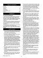
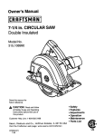
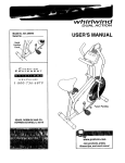
Operator's Manual
18 Gauge
3/8- 13/8"Length
BRAD NAILER
Model No.
351.181730
CAUTION:
Read and follow
all Safety Rules and Operating
Instructions before First Use
of this Product. Keep this
manual with tool.
Sears, Roebuck and Co., Hoffman Estates, IL 60179 U.S.A.
www.sears,com/craftsman
20347.01 Draft (04/30/03)
•
•
•
•
•
Safety
Operation
Maintenance
Parts List
Espahol
Warranty .........................................
Safety Rules ......................................
2
2
Operation ......................................
Maintenance ....................................
3-5
5-6
Troubleshooting ...................................
Parts Illustration and List ..........................
7
8-9
Espa_ol ......................................
The tool must have a male, free-flow hose coupling so that
all air pressure is removed from the tool when the coupling
joint is disconnected. Failure to use proper coupling could
cause accidental discharge, possibly causing injury.
Only use air hose that is rated for a maximum working
pressure of 150 psi or 150% of the maximum system pressure, whichever is greater,
Do not use a hose swivel connector with this tool.
Do not pull trigger or depress contact trip while connecting
to the air supply, as the tool may cycle, possiblycausing
injury,
10-15
When loading tool: Do not pull trigger or depress contact
trip; Do not point the toot at yourself or others; Do not
place hand or any part of body in the fastener discharge
area of the tool as accidental actuation may occur and
cause injury.
FULL ONE YEAR WARRANTY
If this product fails due to a defect in material or workmanship
within one year from the date of purchase, Sears will at its
option repair or replace it free of charge. Contact your nearest
Sears Service Center (1-800-4-MY-HOME) to arrange for product repair, or return this product to place of purchase for
replacement.
•
Disconnect tool from air supply before loading or unloading, performing tool maintenance, clearing a jammed fastener, leaving work area, moving tool to another location or
handing the tool to another person.
If this product is used for commercial or rental purposes, this
warranty will apply for 90 days from the date of purchase.
•
Use Sears recommended fasteners only.
•
Do not load the tool until you are ready to use it.
This warranty applies only while this product is used in the
United States.
•
Always assume that the tool contains fasteners. Keep the
tool pointed away from yourself and others at all times.
Never engage in horseplay. Never pull the trigger unless
the contact trip is in contact with the workpiece. Keep others at a safe distance from the tool while the tool is in
operation.
•
Always remove finger from trigger when not driving fasteners. Never carry the tool with finger on or under the trigger
as accidental actuation may occur and cause injury.
•
Always keep hands and body away from the fastener discharge area when air supply is connected to the tool. Grip
tool firmly to maintain control while allowing tool to recoil
away from work surface as fastener is driven, If contact trip
is allowed to recontact work surface before trigger is
released, an unwanted fastener may be driven.
•
Check operation of the contact trip frequently. Never use
the tool if the contact trip, trigger or springs have become
inoperable, missing or damaged. Do not alter or remove
contact trip, trigger or springs. Never use a tool that is leaking air, has missing or damaged parts, or requires repair.
•
Do not drive fasteners on top of other fasteners or with the
tool at too steep an angle. The fasteners can ricochet and
cause injury. Do not drive fasteners close to the edge of
the workpiece. The workpiece is likely to split, allowing the
fastener to fly free and cause injury. Do not attempt to
drive fasteners into hard or brittle materials such as concrete, steel or tile.
This warranty gives you specific legal rights, and you may also
have other rights which vary from state to state.
Sears, Roebuck and Co., Dept. 817WA, Hoffman Estates,
IL 60179
Read and follow all safety rules and operating instructions
in this manual and on warning label of tool before using
this tool. Keep this manual with the tool.
Keep work area clean and properly lighted.
•
•
Keep children, bystanders and visitors at a safe distance
from work area while operating this tool.
Air tool operators and all others in work area should
always wear safety goggles complying with United States
ANSI Z87.1 to prevent eye injury from fasteners and flying
debris when loading, operating and unloading this tool.
Everyday eyeglasses have only impact resistant lenses.
These are NOT safety glasses. ANSI Z87.1 safety glasses
have permanently attached rigid, hard plastic side shields
and will have "Z87.1" printed or stamped on them.
Always wear ear protection. The work area may include
exposure to excessive noise levels which will require necessary ear protection. Some environments will require
head protection; use head protection conforming to ANSI
Z89.1.
Do not overreach. Always place yourself in a firmly balanced position when using or handling the tool. Do not
attach the hose or tool to your body.
Do not operate tool without fasteners or damage to tool
may result.
•
Do not alter or modify this tool in any way. Do not use this
tool for any application other than for which it was
designed.
•
Do not use oxygen, carbon dioxide, high-pressure compressed gas or bottled gases as the power source for this
tool. The tool will explode and serious personal injury
could result,
Do not use tool without safety warning label. If label is
missing, damaged or unreadable, contact SEARS to
obtain a new label.
•
Never connect the tool to air pressure which could potentially exceed 200 psi, Use only clean, dry, regulated air
within rated range as marked on tool,
When servicing a tool, use only identical repair parts.
Store tool out of reach of children and other untrained
persons.
© Seam, Roebuck and Co.
Only qualified repair personnel must perform tool service.
2
Dirt and abrasive materials present in all air lines will
damage tool O-rings, valves and cylinders.
Moisture will reduce tool performance and life if not
removed from compressed air.
DESCRIPTION
The Craftsman 18 Gauge Brad Nailer drives brads from ¾" to
13/8
" long. OUless design eliminates daily oiling and oil stains
on workpiece. Die cast magnesium body with textured rubber
grip minimizes operator fatigue. Large capacity, side loading
magazine with positive, quick action latch makes loading easy.
Nailer features rear exhaust, single and rapid-fire operation,
adjustable depth of drive control, rubber nose tip and storage
case. Safety feature disables tool unless contact trip is pressed
against workpiece. Tapered nosepiece provides operator with
greater visibility for precise fastener placement. Rigid nosepiece reduces jamming. The 18 Gauge Brad Nailer is excellent
for molding, furniture making, and picture framing.
SPECIFICATIONS
Capacity ..............................
100 brad nails
Nail size ......................
18 gauge (.049" x .040")
Nail lengths ................................
9"/_6"
Height ........................................
Width ........................................
73/."
23/,o"
Weight .....................................
2.7 Ibs.
BRAD NAILS
18 gauge brad nails, 3/,/,long
18 gauge brad nails, %" long
18 gauge brad nails, %" long
Keep air filter clean. A dirty filter will reduce the air pressure
to the tool causing a reduction in power and efficiency.
The air supply system must be able to provide air pressure
of 60 to 100 pounds per square inch at tool.
•
All hoses and pipes in the air supply system must be clean
and free of moisture and foreign particles. Hoses must be
rated for a maximum working pressure of 150 PSI or 150%
of maximum system pressure, whichever is greater.
•
Do not mount swivel connector in air supply line.
•
The air pressure should be properly regulated.
•
Different workpiece materials and different fastener lengths
will require different operating pressure.
60-100 PSI
'/," N.P.T.
Length .......................................
19172 Box of 1000) ..........
18343 Box of 5000) ........
19173 Box of 1000) ........
•
3/,to 13/,"
Operating pressure ........................
Air inlet ...................................
18340 Box of 5000) .........
18341 Box of 5000) .........
19171 Box of 1000) .........
18342 Box of 5000) ..........
A filter-regulator-lubricator system is required and sbouId be
located as close to tool as possible. A distance of less than
15 feet is recommended. Lubricator is not required for
oilless tools.
Be sure all connections in air supply system are sealed to
prevent air loss.
•
Never connect a female quick-disconnect coupling to the
tool side of air line connection. A male, free-flow coupling
should be connected to the tool side of air line connection
(see Figure 1).
WARNING= The female coupling provides a seal preventing
loss of compressed air from compressor tank when disconnected from male coupling, if connected to tool side of air
supply, the female coupling could seal a compressed air
charge in the tool which could discharge if the tool trigger is
actuated.
18 gauge brad nails, 1" long
18 gauge brad nails, 1" long
18 gauge brad nails, 1V," long
....
Male Connector
18 gauge brad nails, 1_/," long
AIR SUPPLY LINE
Refer to Figure 1.
DANGER: Do not use oxygen, carbon dioxide, high-pressure
compressed gas or bottled gases as the power source for this
tool. The tool will explode and serious personal injury could
result.
•
The air tool operates on compressed air at pressures from
60 to 100 PSI.
•
Never connect the tool to air pressure which could potentially exceed 200 PSI. Use only clean, dry, regulated air
within rated range as marked on tool.
Air Delivery Required: 0,85 SCFM @ 90 PSI
(30 shots per minute),
WARNING: Keep hands and body away from discharge area
of tool when connecting air supply, Always disconnect tool
from air supply when servicing or adjusting tool and when tool
is not in use,
•
Air operated tools require clean, dry, lubricated compressed air to ensure top performance, low maintenance
and long life.
Figure I - Air Supply Line
LOADING
Refer to Figures 2, 3 & 4 (page 4).
WARNING: Disconnect tool from air supply. Do not load tool
until you are ready to use it. Do not pull trigger or depress
contact trip while loading tool. Always load with nose of tool
pointing away from you and others. Always wear safety goggles that comply with United States ANSI Z87.1.
NOTE: For best results, use Sears fasteners only.
NAILING OPERATION
Depress latch and slide magazine cover open (see
Figure 2).
Refer to Figures 5, 6, 7 & 8 (pages 4 and 5).
WARNING:
Read and follow all safety rules and operating
instructions in this manual and on warning label of tool before
using this tool. Keep this manual with the tool.
WARNING:
Do not use this tool without safety warning
label. If label is missing, damaged or unreadable, contact
Sears to obtain a new label.
WARNING:
Never operate tool unless contact trip is in contact with workpiece. Do not operate tool without fasteners or
damage to tool may result. Never fire fasteners into the air
because fasteners may injure operator or others and damage
to tool may result.
Perform "Safety Mechanism Check" as described in the
Maintenance section (see page 6) prior to first use of tool
and on a daily basis thereafter.
Figure 2 - Open Magazine
The tool is equipped with a rotating switch that can be set
to rapid-fire or single-fire mode (see Figure 5). When the
switch is set to single-fire mode, the tool will not drive a
second fastener until the trigger is fully released and
pulled again.
Insert fasteners into magazine. Position fasteners at bottom
of magazine with head towards top of tool (see Figure 3).
•
When the switch is rotated to rapid-fire
drive fasteners continuously. A fastener
time the contact trip is pressed against
long as the trigger is maintained in the
mode, the tool can
will be fired each
the workpiece, as
pulled position.
Figure 3 - Load Magazine
Slide magazine cover forward over magazine until latch
snaps into place, locking magazine cover (see Figure 4).
Figure 5 - Push and rotate switch to select
Operation Mode
SINGLE-FIRE OPERATION:
•
The air tool is equipped with a contact trip safety mechanism that disables tool unless contact trip is pushed
against work. To drive a fastener hold body firmly and
press contact trip on workpiece where fastener is to be
applied. Pull trigger to drive fastener into workpiece. To fire
a second fastener lift the tool from the workpiece, release
the trigger and then repeat the above sequence.
RAPID-FIRE OPERATION:
•
Figure 4 - Close Magazine
4
The tool can also be operated by holding trigger
depressed and pushing contact trip against workpiece. A
fastener will be driven each time the contact trip is pushed
against the workpiece. This operating procedure provides
rapid-fire fastener driving. Never operate tool unless contact trip is in contact with workpiece.
LOAD INDICATOR
WARNING: All air power fastening tools recoil when operated. This recoil is caused by rapid driving of the fastener. Tool
may bounce from recoil causing a second unwanted fastener
to be driven. Reduce tool bounce by holding tool firmly in
hand and pressing tool gently against workpiece. Let the tool
do the work. This will allow recoil of tool to bounce tool away
from workpiece preventing the driving of second fastener.
The tool is equipped with a load indicator.The load indicator
(colored red) will be visible through the magazine cover window when there are no fasteners in the magazine.
CONTACT TRIP ADJUSTMENT
The contact trip may be adjusted up or down to vary the
depth of the fastener in the workpiece. To adjust, rotate depth
control knob (see Figure 6) to raise or lower contract trip to
desired setting.
Figure 8 - Load Indicator
OPERATING PRESSURE
•
Use only enough air pressure to perform the operation. Air
pressure in excess of that which is required will make the
operation inefficient and may cause premature wear or
damage to the tool.
•
Determine minimum air pressure required by driving some
test fasteners into the workpiece. Set air pressure so that
test fasteners are driven down flush with the work surface.
Fasteners driven too deep may damage workpiece.
Figure 6 - Setting Depth Control
CONTACT TRIP PAD
The tool is equipped with a contact trip pad (see Figure 7)
that prevents marring of finished surfaces by the contact trip
during normal operation. Pad can be removed and stored on
the storage sleeve located on the end cover of the magazine,
Hex wrench is also stored on the magazine.
COLD WEATHER OPERATION
CAUTION: Do not store in cold environment. Frost or ice
could form inside tool affecting operation and damaging tool.
Use a cold temperature lubricant, such as ethylene glycol,
when operating tool in freezing temperatures.
Refer to Figure 9 (page 8).
LUBRICATION
This is an oilless tool. No lubrication is necessary.
MAGAZINE AND PISTON-RAM
•
Keep magazine and nose of tool clean and free of any dirt,
lint or abrasive particles.
The tip of the ram (Fig. 9, No. 11) can become dented or
rounded over time.
•
Figure 7 - Storing Contact Trip Pad and Wrench
5
Square off the tip of the ram with a clean, fine hand file to
extend the life of the ram and tool. Fastener firing will be
more consistent if the ram tip is kept clean and square.
SAFETY MECHANISM CHECK
Inspect contact trip safety mechanism daily for proper operation. Do not operate tool if mechanism is not operating
properly.
With the red push-button switch in the rapid-fire mode, perform the following procedures to test safety mechanism:
•
Leave trigger untouched while pushing contact trip into
workpiece. Tool must not fire.
•
Pull trigger while contact trip is clear of work and pointed
away from operator and others. Tool must not fire.
Depress and hold trigger. Push contact trip against work
where fastener is needed. The tool should drive only one
fastener each time the contact trip is pushed against
workpiece.
If contact trip mechanism does not operate properly,
repair tool immediately through Sears Service Center.
Replace any damaged or missing parts. Use the parts list to
order parts.
REBUILD KITS
Rebuild kits are available as spare parts, (see page 9), Tools
should be rebuilt if tool fails to operate properly after extended
use. See troubleshooting to determine required replacement
parts.
Disconnect tool from air supply before attempting repair
or adjustment,
NOTE: When replacing O-rings or cylinder, lubricate with
grease before assembly.
6
SYMPTOM
POSSIBLE
CAUSE(S)
CORRECTIVE
ACTION
Trigger cap leaks air
1. O-ring damaged
2. Valve stem, seal or O-rings damaged
1. Check and replace damaged O-ring (Fig. 9, No. 55)
2. Check and replace damaged stem, seal or O-rings
(Fig. 9, Nos. 55, 56, 57 and 60)
Cap leaks air
1. Cap bolts loose
2. Damaged gasket
1. Tighten bolts (Fig. 9, No. 1)
2. Check and replace damaged gasket (Fig. 9, No. 3)
Nose leaks air
1. Damaged cylinder O-ring
2. Damaged bumper
3. Ram guide damaged
1. Check and replace damaged O-ring (Fig. 9, No. 12)
2. Check and replace damaged bumper (Fig. 9, No. 14
3. Check and replace guide (Fig. 9, No. 15)
Tool will not operate
1. Insufficient air supply
2. Damaged or worn head valve O-ring
or seal
1, Check air supply
2. Replace damaged or worn O-ring or seal
(Fig. 9, Nos. 5 and 9)
3. Damaged head valve spring
4. Head valve binding in cap
3, Replace damaged spring (Fig. 9, No. 6)
4. Clean and grease cap and head valve
(Fig. 9, Nos. 2 and 9)
1.
2.
3.
4.
5.
1.
2.
3.
4.
Tool operates slowly
or loses power
Tool skips fasteners or
inconsistent operation
Damaged head valve spring
Damaged or worn O-rings
Damaged trigger assembly
Build-up on ram
Cylinder not sealed on bumper
properly
Check and replace damaged spring (Fig. 9, No. 6)
Check and replace damaged or worn O-rings
Check and replace trigger assembly
Clean piston/ram assembly (Fig. 9, No. 11)
5. Disassemble cylinder and assemble properly
6. Insufficient air supply
7. Head valve poorly lubricated
6. Check air supply
7. Disassemble head valve (Fig. 9, No. 9),
clean, grease, and assemble properly
1. Worn or damaged bumper
2. Build-up on ram or nose
1. Check and replace bumper (Fig. 9, No. 14)
2. Clean and grease piston/ram assembly(Fig. 9, No. 11)
and inside of nose cover (Fig. 9, No. 21)
3. Check air supply
4. Check and replace O-ring (Fig. 9, No. 10)
3.
4.
5,
6.
Insufficientair supply
Damaged or worn piston O-ring
Damaged magazine springs
Magazine-nose bolts loose
5. Check and replace springs (Fig. 9, No. 34)
6. Align nose with magazine and tighten bolts
(Fig. 9, No, 24)
7. Use Sears recommended fasteners only
8, Discard damaged fasteners
9. Use Sears recommended fasteners only
10. Tighten cap bolts (Fig. 9, No. 1). Check and replace
damaged gasket (Fig. 9, No. 3)
11. Check and replace damaged seal and O-rings
(Fig. 9, Nos. 55, 57 and 60)
12. Check and replace damaged piston/ram assembly
(Fig. 9, No. 11)
13. Clean magazine and lubricate with a
dry, film lubricant.
14. Check and replace magazine (Fig. 9, No. 37)
7. Fasteners too short
8. Damaged fasteners
9. Incorrect fastener size
10. Cap leaks
11. Damaged trigger valve seal and
O-rings
J12. Bent or damaged ram
13. Dirty magazine
14. Damaged orworn magazine
7
Model 351.181730
Figure 9 - Replacement
Parts Illustration
For Nailer
I
I
5O
41
_
45
34
J
21
25
31
8
KEY
NO.
KEY
NO.
PART NO.
DESCRIPTION
7
37
20344.00
Cap
1
38
06086.00
Cap Gasket
Spacer
Seal
1
1
1
39
40
20299.00
17437.00
Magazine
4-0.7 x 8mm Socket Head Bolt
Push Button
41
PART NO.
DESCRIPTION
QTY.
1
06395.00
4-0.7 x 22mm Socket Head Bolt
2
20333.00
3
4
5
20273.00
20274.00
20275.00
QTY.
1
3
Spring
1
1
20246.00
3 x 23ram Spring Pin
2
20300.00
Trigger
1
2
6
04210.00
Head Valve Spring
1
42
7
06436.00
Spacer
1
43
20301.00
8
9
04303.00
04302.00
33.5 x 2.OmmO-Ring
Head Valve Piston
1
1
44
06078.00
45
20302.00
2.5 x 24mm Spring Pin
4-0.7 x 12mm Socket Head Bolt
Washer
10
20277.00
Seal
1
46
20303.00
Rear Support
1
11
20334.00
Piston Ram Assembly
1
12
13
06909.00
20335.00
44.17 x 1.78mm O-Ring
Cylinder
1
1
47
48
20276.00
06080.00
3 x 33mm Spring Pin
4-O.7mm Fiber Nut
1
1
49
N/A
14
15
20280.00
20281.O0
Bumper
Ram Guide
1
1
50
04327.00
1
1
51
20304.00
Body
9.8 x l.gmm O-Ring
Air Manifold
16
20282.00
Throttle
1
52
20305.00
29.82 x 2.62 mm O-Ring
1
17
18
20336.00
20284.00
Contact Trip Guide
Pad
1
4
53
54
20306.00
20307.00
Trigger Spring
1
Trigger Cap
1
19
20337.00
Contact Trip
1
55
20308.00
10.82 x 1.78mm O-Ring
Valve Stem
1
20309.00
57
06449.00
2
2
5
1
20
21
20286.00
20338.00
Contact Trip Pad
Nose Cover
1
1
56
22
04345.00
Shoulder Screw
2
58
04325.00
2.5 x 1.4ram O-Ring
Trigger Valve Spring
23
24
06079.00
20339.00
4-0.7 x 16mm Socket Head Bolt
Nose
1
1
59
20310,00
Trigger Valve Head
25
26
20895.00
20340.00
2 x 12mm Spring Pin
Left Plate
4
1
60
61
20311.00
20312.00
7.5 x 1.5mm O-Ring
Latch
62
20313.00
Lever
1
1
27
20341.00
Pusher
1
63
20314.00
28
20291.00
Load Indicator
1
64
20345.00
Latch Spring
End Cover
1
1
29
30
01939,00
06088.00
3 x 20mm Spring Pin
4-0.7 x 10mm Socket Head Bolt
1
1
65
20502.00
Trip Lever
1
66
20547.00
20342.00
20293.00
Right Plate
Nut
1
1
67
68
20503.00
20548.00
E-Ring
Nut
1
31
32
Nut Guide
1
33
20343.00
Magazine Cover
1
69
20549.00
Knob
1
A
20346.00
Warning Label
20347.01
Operator's Manual
1
1
9-18335
Storage Case
1
34
35
20295.00
20296.00
Pusher Spring
Wear Plate
1
1
36
20297.00
Lever Lock
1
A
Qty./Box
Model No
18 Gauge Brad Nails, %" Long
18 Gauge Brad Nails, ¾" Long
5000
5000
9-18340
9-18341
A
18 Gauge Brad Nails, %" Long
18 Gauge Brad Nails, 1" Long
1000
5000
9-19171
9-18342
A
A
18 Gauge Brad Nails, 1" Long
1000
18 Gauge Brad Nails, 1V," Long 5000
9-19172
9-18343
A
1
1
1
1
Standard hardware item available locally
Not Shown
Recommended Accessories
h
1
18 Gauge Brad Nails, 1V," Long
1000
9-19173
Rebuild Kits
A
20318,00
Trigger Rebuild Kit
Fig, 9, Nos. 53, 55, 56, 60 and
two 57
1
A
20319.00
Head Valve Rebuild Kit
1
A
20348.00
Fig. 9, Nos. 3, 4, 5 and 8
Piston-Ram Assembly Rebuild Kit
Fig. 9, Nos. 10, 11, 12 and 14
1
Your Home
Para pedir servicio de reparaci6n
a domicilio, y para ordenar piezas:
1-888-SU-HOGAR
sM
Au Canada pour service en fran£ais:
1-800-LE-FOYER
Mc
(1-800-533-6937)
www.sears.ca
® Registered Trademark / TM Trademark / SM Service Mark of Sears, Roebuck and Co.
® Marca Registreda / TM Mama de F_.brica / SM Marca de Serviciode Sears, Roebuck and Co.
MC Marque de commerce
/ MD Marque d&posde de Sears, Roebuck
and Co.
© Sears, Roebuck
and Co.