1
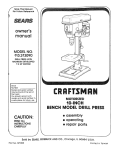
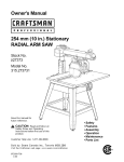
Owner'sManual
ERRFTS],IHJI.
l_
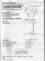
Bench Model
213HP(MaximumDeveloped)
5 Speeds(3[0-3600R.P.M.)
112lnchGhuck
l2.INCHDRILLPRESS
ModelNo.
137.219120
CAUTION:
BeforeusingthisDrillPress,
readthismanualandfollow
all its SafetyRulesand
Instructions.
Operating
SafetyInstructions
lnstallation
Operation
Maintenance
PartsList
Espafrol
Gustomer HelP Line
1.800-843'1682
Sears,Roebuck and Co., Hoffman Estates, lL 60179
USA
PartNo.137219120001
SECTION
PAGE
Warranty
ProductSpecifications.....
Safetylnstructions..
AccessoriesandAttachments..
CartonContents
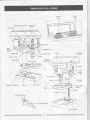
KnowYourDrill Press. . .
Glossaryof Terms
Assemblyand Adjustments
Operation
M a i n t e n a n c.e.
Troubleshootingguide
Parts
........2
........2
....3
.....6
........6
. . . . . .8
. . . . . .g
. . .10
.......16
...20
.......21
.. . ...22
CHUCKSIZE
.i/2'
SPEEDS
.5 (540-3,600
RPM)
MOTOR
. 1 2 0 V6 0 H Z ,6 A M P S ,
H O R S E P O W E R . . . . . . 213
. HP (Max.Developed)
TABLESIZE .
10-5/16"x 8-21132"
TABLETILT .
, -3 ^'^,
+5
fllLzt-l
SPINDLE
TRAVEL
2-3/8'
THROAT
o
BASESIZE .
i 4-318'x 8-114"
HEIGHT
37-3t32',
| \Jl-{
LEt"
I
To avordelectricalhazards.fire hazar0s.3r f,amaqeio
the tool,use propercircuitprotectton.
Yourdrrllpressis wired at the factoryfcr 12OVooeratron
and use a
Connectto a 120V,15 AMP branchcrrcurt
15 AMP trmedelayfuseor circuitbreakerTo avordshoci
or fire,replaceoowercord rmmediateivf ,t g ry91'11.
69161
damagedin any way.
Somedust createdby powersanding,sawing,grrnding,
drilling,and otherconstruction
activities
containschemicalsknown[to the Stateof California]
to cause cance( birthdefectsor other
reproductive
harm. Someexamples
of thesechemicals
are:
paints.
a Leadfromlead-based
products.
siiicafrom bricks, cementand othermasonry
o Crystalllne
lumber.
o Arsenicand chromiumfromchemicaily-treated
Ycurriskfromtheseexposures
varies,depending
on howofienyoudo thistypeof work.Toreduce
yourexposureto thesechemicals:work
in a weilventilated
area,andworkwithapproved
safety
:cuiipment.
designed
to fiiteroutmicroscopic
carticles.
sucnas thosedusimasksthatarespecially
GENERAL
SAFEW INSTRUCTIONS
BEFORE
USINGTHEDRILLPRESS
Safetyis a combinationof common sense, stayingalert
and knowinghow to use your drill press.
14. REMOVE
ADJUSTING
KEYSANDWRENCHES.
Fromthe habitof checkingto seethat keysand
adjustingwrenchesare removedfromthe toolbefore
turning"ON".
15. NEVERLEAVETOOL
RUNNING
UNATTENDED.
"OFF".Don'tleavethetooluntil
TURNTHEPOWER
it comesto a completestop.
Toavoidmistakesthatcouldcauseseriousinjury,do not 16. NEVERSTANDONTOOL.Seriousinjuiycouldoccur
plugthe drillpressin untilyou havereadand understood
if thetoolis tippedor if thecuttingtoolis unintentionally
thefollowing:
contacted.
1. READandbecomefamiliarwiththisentireinstruction 17.DON'TOVERREACH.
Keepproperfootingand
manual.
LEARNthetool'sapplications,
limitations,
and
balance
at alltimes.
possible
hazards.
18. MAINTAINTOOLSWITH
CARE.Keeptoolssharp
2. KEEPGUARDSlN PLACEandin workingorder.
and cleanfor bestand safestperformance.
Follow
instructions
for
lubricating
and
changing
accessories.
3. DON'TUSEIN A DANGEROUS
ENVIRONMENT.
Don'tuse powertoolsin dampor wet locations,
or
19. CHECKFORDAMAGED
PARTS.
Beforefurtheruseof
exposethemto rain.Keepworkareawelllighted.
thetool,a guardor otherpartthatis damagedshould
4. DO NOTusepowertoolsin thepresence
be carefullycheckedto determinethat it will operate
of flammable
properlyand performits intendedfunction.Checkfor
liquidsor gases.
alignment
of movingparts,bindingof movingparts,
5. KEEPWORKAREACLEAN.Ctuttered
areasand
breakage
of parts,mounting,
andanyotherconditions
benchesinviteaccidents.
that mayaffectits operation.
A guardor otherpartthat
is damagedshouldbe properlyrepaired
or replaced.
6. KEEPCHILDREN
AWAY.
Allvisitors
shoutdbe keptat
a safedistancefromthe workarea.
20. MAKEWORKSHOP
KIDPROOF
withpadlocks,
master
switches,
or by removing.starter
keys.
7. DON'TFORCETHETOOL.tt wiildo thejob beter
and saferat the ratefor whichit wasdesigned.
21. DO NOToperatethetoolif youareunderthe influence
of anydrugs,alcoholor medication
thatcouldaffect
8. USETHERIGHTTOOL.Don'tforcetootor the
yourabilityto usethe toolproperly.
attachment
to db a job for whichit was notdesigned.
9. WEARPROPER
APPAREL.
DONOTweartoose
clothing,gloves,neckties,rings,bracelets,
or other
jewelrywhichmaygetcaughtin movingparts.
Nonslipfootwearis recommended.
Wearprotective
haircovering
to containlonghair.
10.WEARA FACEMASKOR DUSTMASK.
produces
Drilling
operation
dust.
11. DISCONNECT
TOOLSbeforeservicing,
andwhen
changingaccessories,
suchas blades,bits,cutters,
andthe like.
12. REDUCETHE
RISKOF UNINTENTIONAL
STARTING.
Makesuretheswitchis in "OFF'position
before
plugging
in.
13. USERECOMMENDED
ACCESSORTES.
Consutt
the
owner'smanualfor the recommended
accessorres.
The useof improperaccessories
rrr€ly
causeriskof
injuryto persons.
22. Dustgenerated
fromcertainmaterials
canbe
hazardous
to yourhealth.Alwaysoperatethe drill
pressin a well-ventilated
areaand providefor proper
dustremoval.
Usedustcollection
systemswhenever
possible.
23.ALWAYSWEAREYE
PROTECTION.
Anydrillpress
canthrowforeignobjectsinto
theeyeswhichcouldcause
permanent
eyedamage.
ALWAYS
wearSafetyGoggles
(notglasses)
thatcomplywith
ANSI safety standard287.1. Everydayeyeglasses
haveonly impact-resistant
lenses.They ARE NOT
safetyglasses.SafetyGogglesare availableat Sears.
NOTE:Glassesor gogglesnot in compliancewith
ANSI 287.1 couldseriouslyhurt you when they break.
SAVETHESEINSTRUCTIONS
SPECIFIC
SAFETYINSTRUCTIONS
FORTHE"DRILLPRESS
Foryourownsafety,do nottry to useyourdrillpress
andinstalled
or plugit in untilit is completely
assembled
according
to the instructions,
anduntilyouhavereadand
manual:
understood
thisinstruction
WORK.Useclampsor a viseto holdthe
14. SECURE
lt's saferthanusingyourhand
rvorkwhenpractical.
and it freesbothhandsto operatetool.
15. WHENusinga drillpressvise,alwaysfastento the
table.
andlocksarefirmly
16. MAKESUREallclamps
beforedrilling.
tightened
LOCKTHEHEADandtablesupportto
1. YOURDRILLPRESSMUSTBE BOLTEDsecurel/ 17. SECURELY
the tableto the tablesupportbefore
and
the
column,
In addition,if thereis anytendency
to a workbench.
the drillpress.
operating
for yourdrillpressto moveduringcertainoperations,
to the floor.
boltthe workbench
the
18. NEVERturnyourdrillpresson beforeclearing
(tools,scrapsof wood,etc.)
all
objects
table
of
for usein dry
2. THISDRILLPRESSis intended
indooruseonly.
conditions,
jog the motor
the operation,
19. BEFORESTARTING
doesnotwobbleor
drill
bit
sure
the
to
make
switch
3. WEAREYEPROTECTION.
USEfaceor dustmask
vibrate.
alongwithsafetygogglesif drillingoperationis dusty.
duringextendedperiods
especially
USEear protectors,
20. LETTHESPINDLEREACHFULLSPEEDbefore
of operation.
to drill.lfyourdrillpressmakesan unfamiliar
starting
stopimmediately,
noiseor if it vibratesexcessively,
4. DO NOTweargloves,neckties,or looseclothing.
turnthedrillpressoffandunplug.Do notrestartuntil
the problemis corrected.
too smalltobe securely
5. DO NOTtry to drillmaterial
held.
or set up workon
21.DO NOTperformlayoutassembly
pressis in operation.
drill
while
the
table
the
6. ALWAYSkeephandsout of the pathof a drillbit.
Avoidawkwardhandpositionswherea suddenslip
and
SPEEDfordrillaccessory
22. USERECOMMENDED
couldcauseyourhandto moveintothe drillbit.
that
come
SEEINSTRUCTIONS
material.
workpiece
with
the
accessory.
7. DO NOTinstallor useanydrillbit thatexceeds
175mm (7")in lengthor extends150mm (6")below
23. WHENDRILLINGlargediameterholes,clampthe
the chuckjaws.Theycansuddenlybendoutwardor
thebit may
firmlyto thetable.Otherwise,
workpiece
break.
at highspeed.DO NOT
grabandspintheworkpiece
holecutters,as they
USEfly cuttersor multiple-part
8. DONOTUSEwirewheels,routerbits,shapercutters,
in use.
unbalanced
or
become
apart
can
come
circle(fly)cutters,or rotaryplanerson thisdrillpress.
9. WHENcuttinga largepieceof materialmakesureit
is fullysupportedat the tableheight.
24. MAKESUREthespindlehascometo a complete
stopbeforetouchingthe workpiece.
freehand.
ALWAYS
10. DO NOTperformanyoperation
firmlyagainstthe tableso it will
holdthe workpiece
not rockor twist.Useclampsor a visefor unstable
workpieces.
starting,always
25. TO AVOIDINJURYfromaccidental
turntheswitch"OFF'andunplugthedrillpressbefore
installing
or removinganyaccessoryor attachment
or makinganyadjustrnent.
11. MAKESUREthereare no nailsor foreignobjectsin
the partof the workpieceto be drilled.
12. CLAMPWORKPIECE
OR BRACEagainsttheleft
sideof the columnto preventrotation.lf it is too short
or the tableis tilted,clampsolidlyto the tableand
usethe fenceprovided.
26. KEEPGUARDSlN PLACEand in workingorder.
TYPECHUCKKEYas
27. USEONLYSELF-EJECTING
providedwiththe drillPress.
overhangs
thetablesuchthat
13. IFTHEWORKPIECE
it willfallor tip if notheld,clampit to thetableor
provideauxiliarysupport.
SAVETHESEINSTRUCTIONS
GROUNDING
INSTRUCTIONS
INTHEEVENTOFA,MALFUNCTION
OR BREAKDOWN,
grounding
providesa pathof leastresistance
for electric
currentand reducesthe riskof electricshock.Thistool
is equipped
withan electriccordthathasan equipment
grounding
conductor
anda.grounding
plug.Theplug
MUSTbe pluggedintoa matching
receptacle
thatis
properlyinstalledand groundedin accordance
withALL
localcodesandordinances.
DONOTMODIFYTHE
PLUGPROVIDED.
If it wiIInotfit the
receptacle,
havethe properreceptacle
installedby a .
qualif
iedelectrician.
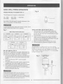
Thistoolis intendedfor useon a circuitthathasa
receptacle
liketheoneillustrated
in FIGURE
A.
plugandreceptacle
FIGUREA showsa 3-prongelectrical
thathasa grounding
grounded
conductor.
lf a properly
receptacle
is notavailable,
an adapter(FIGUREB) can
be usedto temporarily
connectthisplugto a 2-contact
ungrounded
receptacle.
Theadapter(FIGUREB) hasa
rigidlugextending
fromit thatMUSTbe connected
to a
permanent
earthground,suchas a propedygrounded
receptacle
box.TheCanadianElectrical
Codeprohibits
the useof adapters.
CAUTION:ln all cases,makecertainthe receptacle
in
questionis properlygrounded.
lf youare notsurehavea
certified
electrician
checkthe receptacle.
IMPROPER
CONNECTION
of theequipment
grounding
conductor
can resultin riskof electricshock.The
conductor
withthegreeninsulation
(withor withoutyellow
stripes)
is theequipment
grounding
Thisdrillpressis for indooruseonly.Do notexposeto
conductor.
lf repair
or replacement
of the electriccordor plugis necessary, rainor usein damplocations.
DONOTconnecttheequipment
grounding
conductor
to
Fig.A
a liveterminal.
3-ProngPlug
CHECKwitha qualified
electrician
or servicepersonnel
if
youdo notcompletely
understand
thegrounding
instructions,
or if youare notsurethetoolis properly
grounded.
-A-
w
USEONLY3.WIREEXTENSION
CORDSTHAT
HAVE
3.PRONG
GROUNDING
PLUGSAND3.POLE
RECEPTACLES
THATACCEPT
THETOOL'SPLUG.
REPAIR
OR REPLACE
DAMAGED
ORWORNCORD
IMMEDIATELY.
Grounding
Prong
Properly
Grounded
3-ProngReceptacle
Fig.B
Grounding
GUIDELINES
FOREXTENSION
CORDS
Makesure your extensioncord is in good condition.
When usingan extensioncord,be sure to use one heavy
enoughto carrythe currentyour productwill draw.An
undersizedcord will causea drop in line voltageresulting
in loss of powerand overheating.
The tablebelowshows
the correctsize to use accordingto cord lengthand
nameplateampererating.lf in doubt,use the nextheavier
gauge.The smallerthe gaugenumber,the heavierthe cord.
Be sure your extension cord is properly wired and in
good condition.Alwaysreplacea damagedextension
cord or have it repairedby a qualifiedperson before
usingit. Protectyour extensioncordsfrom sharp objects,
excessiveheat and damp or wet areas.
Use a separateelectricalcircuitfor your tools.This circuit
mustnot be less than #12 wire and shouldbe protected
witha 15 Amp time lag fuse.Beforeconnectingthe motor
to the powerline,makesure the switchis in the "OFF"
positionand the electriccurrentis ratedthe same as the
currentstampedon the motornameplate.Runningat a
lower voltagewill damagethe motor.
MakeSureThis
is Connected
to a
KnownGround'
2-Prong
Receptacle
Thistoolmustbe groundedwhilein useto protectthe
operatorfromelectricalshock.
Total.length of cord in feet
more than
not more than
SAVETHESEINSTRUCTIONS
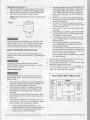
AVAILABLEACCESSORIES
AND CHECKING
UNPACKING
CONTENTS
ESEWI
forthisdrillpress.
recommended
Useonlyaccessories
Useof
accessories.
thataccompany
Followinstructions
maycausehazards.
accessories
improper
do notplugthedrill
lf anypartis missingor damaged,
partis replaced,
pressin untilthe missingor damaged
and assemblyis comPlete.
or seethe Sears
VisityourSearsHardwareDepartment
Powerand HandToolCatalogfor the following
accessories:
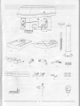
Carefullyunpackthe drillpressand all its parts,and
belgw.
compareagainsttheillustration
.
.
.
.
a protective
To protectthe drillpressfrommoisture,
coatinghasbeenappliedto the machinedsurfaces'
with
Removethiscoatingwitha softclothmoistened
keroseneor WD-40.
Drillbits
Hold-Down
andGuide
DrillPressVises
Kit
Clamping
To avoid fire or toxic reaction,never use gasoline,
naphtha,aceione,lacquerthinneror similarhighly
volatilesolventsto cleanthe drillpress.
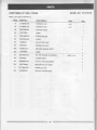
TABLEOF LOOSEPARTS
forthisdrillpressto
designed
Useonlyaccessories
avoidinjuryfromthrownbrokenpartsor workpieces.
ITEM
A.
unlessyouhavecompletely B .
Do notuseanyaccessory
readthe instruction
or owner'smanualfor thataccessory. c.
D.
E.
F.
G,
H.
t.
J.
K.
L.
M.
N.
o.
P.
o.
R.
DESCRIPTION
Headassembly
Base
Table
Columnassembly
Collar
Rack
Loosepartsbag:
Feedhandles
Wormgear
Crankhandle
Lockhandle
Hexbolts
Fenceassembly
knobs
Triangle
Wingnuts
Washers
Hexkeys
Box:
Chuckkey
Chuck
OUANTITY
1
1
I
I
1
1
1
3
1
1
{
I
4
1
2
2
4
2
I
t3
?--=\
Az.
rllt_
-ffi
'r@
,Fv/ts€rygggg
AN
,1-S:l,,
ffi
P
,4#M
'
lcHtJK
r
I
I
;I
AN
/f)
Ly
aeEv 8E
NO
€.
a-f1-lJ
r-a-E
---Kt
:Jlf;1
_atll
:4
tl
"7---rrt l
tl
tl
tl
rl
U
P
o
7
.
g
R
. : . , . " ,.;' ; : 1 . . . . , .
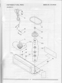
Depthscale stop nuts
Depthscale
pornler
Cordclamp
Oepthscale
Belt
tension
knob
Feed stop rod
Feed spring
h stop
Spindle
Columncollar
Bevel scale
Table support
ON/OFF
switchw/key
Supportlock handle
Fenceendstop
Fencebackstop
Head lock
screw
I
BASE- Supportsthe drillpress.Foradditional
stability, DRILLON/OFFSWITCH- Haslockingfeature.This
and
featureis intendedto helppreventunauthorized
holesare providedin the baseto boltthe drillpressto
lnsert
the
"Specific
others.
possible
and
(See
use
by
children
hazardous
floor.
Instructions
for
Drill
Presses".)
the
Safety
keyintotheswitchto turnthedrillpresson.
BACKUPMATERIAL- A pieceof scrapwoodplaced
by placingthe beltin any
SPEED- Changed
betweenthe workpieceandtable.The backupboard
DRILLING
prevents
in the pulleys.Seethe Spindle
woodin theworkpiece
fromsplintering
whenthe of the steps(grooves)
lt also SpeedChartinsidethe beltguard.
drillpassesthroughthe backside
of theworkpiece.
preventsdrillingintothe tabletop.
FEEDHANDLE- Movesthechuckup or down.lf
pulleys
BELTGUARDASSEMBLY Coversthe
and belt necessary,
one or two of the handlesmaybe removed
duringoperation
of thedrillpress,
the workpieceis of suchunusualshapethatit
whenever
withthe handles.
interferes
- Referto the"Assembly"
BELTTENSION
Section,
"lnstalling
andTensioning
BeltJ'
or
FENCE- Attachesto the tableto alignthe workpiece
Removable.
Removefencewhen
drilling.
forfastrepetitive
BELTTENSIONKNOB- Tightening
withotherdrillpressaccessories.
theknoblocks
it interferes
the motorbracketsupportmaintaining
correctbeltdistance
HEADLOCKS- Locksthe headto the column.ALWAYS
andtension.
the drillpress.
lockthe headin placewhileoperating
BEVELSCALE- Showsthe degreeof tabletilt for bevel
to provideeasy
withgearmechanism
operations.
The scaleis mountedon the sideof the arm. RACK- Combines
elevation
of the tableby the handoperatedtablecrank.
CHUCK- Holdsthe drillbit or otherrecommended
-The numberof
accessory
to performdesiredoperations.
PERMINUTE(R.P.M.)
REVOLUTION
objectin oneminute.
turnscompleted
by a spinning
CHUCKKEY- A self-ejecting
chuckkeywhichwill pop
out of the chuckwhenyoulet go of it.Thisactionis
of thespindle.
SPINDLE
SPEED- TheR.P.M.
designedto helppreventthrowingof the chuckkeyfrom
the chuckwhenthe poweris turned"ON".Do not use
SPRINGCAP- Adjustsquillspringtension.
anyotherkeyas a substitute;
ordera newoneif damaged
or lost.
TABLE- Providesworkingsurfaceto supportworkpiece.
COLUMN- Connectsthe head,table,and baseon a
one-piece
tubefor easyalignment
and movement.
TABLEBEVELLOCK- Locksthetablein anyposition
from0o- 45o.
COLUMNCOLLAR- Holdsthe rackto thecolumn.
Rackremainsmovablein the collarto permittable
cupportmovements.
andlowerstable.
TABLECRANKHANDLE- Elevates
Turnclockwise
to elevatetable.Supportlockmustbe
crank.
releasedbeforeoperating
- Supports
COLUMNSUPPORT
thecolumn,guidesthe
rackand providesmountingholesfor columnto base.
LOCK-Tighteninglocksthetable
TABLESUPPORT
supportto the column.Alwayshaveit lockedin place
thedrillpress.
whileoperating
DEPTHSCALE- lndicatesdepthof holebeingdrilled
- Rideson thecolumnto supportthe
TABLESUPPORT
table.
- Indicates
DEPTHSCALEPOINTER
thedrillingdepth
by pointingto the depthscale.
- Material
beingdrilled.
WORKPIECE
DEPTHSCALESTOPNUTS- Locksthe depthscaleto
selecteddepth.
DRILLBIT- Thecuttingtoolusedin thedrillpressto
makeholesin a workpiece.
I
,,..:.:i':,,.'.:,i:'ri
ll... :,':r,::l:
rl.':.,
ASSEMBLYINSTRUCTIONS
ESEW
For your own safety,neverconnectplug to power source
outletuntilall assemblyand adjustmentstepsare
completed,and you have read and understoodthe safety
and operatinginstructions.
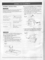
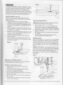
TABLETO COLUMNASSEMBLY(FlG. B THROUGHF)
1. Locatethe worm gear,tablecrank,and tablesupport
lock handlefrom the looseparts bag.
2. Insertthe worm gear (1) into the tablecrank handle
hole (2) from insidethe tablesupport(3).Make sure
the worm gear (1) mesheswith the insidegear'
3. Insertthe iable supportlock handle(4) intothe hole
at the rearof the tablesupport.Tighten'
NOTE:Tableremovedfrom support in illustrationfor
clarity.
Fig.B
Slotted screwdriver
8" & 10"Adjustablewrenches
(
/r\#1
wrench
Combination
*%
square
Combination
t-t
tt
oA
rr--!-_--i:r
\l+t':.t
Framingsquare
Socketwrench
with 23 mm. socket
4. Placethe rack(5)in positioninsidethetablesupport(3)'
makingsurethewormgear(1)on the insideof the
tablesupportis engagedwiththeteethof the rack'
The Drill Press is very heavy and MUST be liftedwith the
helpof 2 PEOPLEOFtMORE,to safelyassembleit'
coLUMN SUPPORTTOBASE (FlG. A)
1. Positionbase (1) on floor.
2. Placecolumn(2) on base,aligningholesin column
supportwith holesin base.
3. Locatefour long hex bolts (3) from loose parts bag.
1. Placea bolt in each hole throughthe column
supportand the base.Tightenwith an adjustable
wrencn.
Fig.A
10
'h,
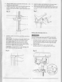
5. Sfide.thetablesupportassemblywiththe rack( 3,5)
togetherontothe column.
6. Engagethe bottomof the rack(5) withthe lip of the
columnsupport(6).Tightenthe supportlock
handle(4) to lockthe tablesupportassemblyto the
column.
8. Instalfthe tablecrankhandle(9) to the wormgear
shaft(1) on the sideof the tablesupport(3).
9. Lineup theflatsideof the shaftwiththe set screw(10)
in the crankhandleandtightenthe screwwitha hex
wrench.
Fig. F
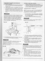
TNSTALL|NGTHE
HEAD(Ftc.c)
Installthecoltar(7) to the top end of the rack(5) on
the column,
IMPORTANT:
The botromof the coltgrMUSTNOT
be pushedall the waydownontotheiop of the
rack.MAKESUREthe top of the rackis under
the bottomof the collarandthatthereis enough
clearanceto allowthe rackto freelyrotatearound
the column.Tightenthe set screw(e).
CAUTION:Toavoidcolumnor collardamage,DO
NOTOVERTIGF|IEN
the set screw.
Fig. E
;11
The DrillPressis veryheavyand MUSTbe liftedwith
the helpof 2 PEOPLEOR MORE,to safelyassembleit.
1
Carefullylift head(1) abovethe cotumn(2) and slide
it ontothe column.Makesurethe headslidesdown
overthe columnas far as possible.
Alignthe head
with the base.
2. Usingthe hexwrench,tightenthe two head
lockset screws(3)on the rightsideof the head.
Fig.G
FEED HANDLES (FlG. H)
TNSTALLING
handlesin the loose parts bag'
threeieed
1. Locate
2. Screwthe feed handles(1) into the threadedholes (2)
in the hub (3).Tighten.
CHUCK(FlG-l, J and K)
INSTALLINGTHE
1. Cleanoutthetaperedholein thechuck(1)witha
cleancloth.
2. Cleantaperedsurfaceson the spindle(2).
CAUTION:Makesurethereare no foreignparticles
Theslightestpieceof dirt on
stickingto the surfaces'
anyof thesesurfaceswill preventthe chuckfrom
Thiswillcausethe drillchuckand
seatingproperly.
dirty,usea
bit to wobble.lf taperedholeis extremely
cleaningsolvent.
Fig.I
n
lll
ill
III UI
n-I
iltI
v
E-
g-
2
I
3 . Lowerthe spindle(2) by turningthe feedhandles(3)
counterclockwise.
4 . Pushthe chuckup ontothespindle(2).
Tapgentlyto ensureseat.
5 . Opentnejawsof the chuck(1) by rotatingthe chuck
To preventdamage,makesurethe
sleeveclockwise.
recededintothe chuck'
lawsare completely
Fig. J
or a
Usinga rubbermallet,plastic-tipped.hammer'
chuck
the
tap
firmly
hammer,
a
bl;;k'; woooana
upwardintopositionon the spindleshaft'
Fig.K
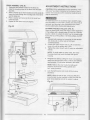
(FlG' L)
SURFACE
DRILLPRESSTOWORK
MOUNING
a
thedrillpressto a workbench,solid
i. tt mounting
overa plywoodboard,to
woodbenchis preferred
reducenoiseandvibration.
throughthesupporting
2. Holesshouldbe pre-drilled
surface.
to mountthisdrillpressis NOT
3. The hardware
tool'The hardwareas shownin
the
with
supplied
be used:
should
illustration
the
Fig.L
.Itt$rrl
ilt|
ilt
ill
o.
1.
2.
3.
4.
5.
6.
7.
8.
9.
1I
nt
tl
{
"l
I
IT-
-\l
nl
\_-/
GJ-sl
Drillpressbase
Bolt
Flatwasher
Rubberwasher
Worksurface
Flatwasher
Lockwasher
Hexnut
Jamnut
I
12
FENCEASSEMBLY(Ftc. M)
1 Determine
thedesiredlocationfor thefence(1).
2. Alignthe mountingholesof the fenceoverthetable
' topslots.
3.
flace q washer(2)on thethreadedendof the knob(3).
lnsertthe knobthroughthe mountingholeof thefence
andthetableslot.
4. Placea washerandwingnut(4)on the knobfrom
underthetable.
5. Repeatfor the otherknobandtighter.r.
Fig.M
ADJUSTMENT
INSTRUCTIONS
CAUTION:Allthe adjustmentsfor the operationof the
drill press have been completedat the factory.Due to
normalwear and use, some occasionalreadjustments
may be necessary.
Toavoidinjuryfroman accidentalstart,
ALWAySmake
surethe switchis in the"OFF"position,theswitchkeyis
removed,
andthe plugis notconnected
to thepower
sourceoutletbeforemakingbeltadjustments.
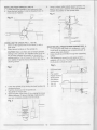
ALTGNTNGTHE
BELTPULLEYS(Ftc. N)
Openthe headcoverof the Drillpress.Checkalignment
of the pulleyswitha straightedge(5) suchas a fiaming
square,a level,or a pieceof wood.Laythe straightedge
acrossthe top of the pulleys.lf all threepulleysare wOt
aligned:
1. Releasebeltpressureby loosening
the belttension
lockknobs(2) on eithersideof the head,
counterclockwise.
2. Loosenthe motormountnuts(3).Liftor lowerthe
motor(4) untilthe pulleysare in line.
3. Tightenthe motormountnuts(3) usingan adjustable
wrench.
NOTE:llo avoidrattlesor othernoise,the motor
housingshouldnottouchthe lowerbeltguard
housing.
4 . Retighten
the beltby pullingthe motor(4)towardor
awayfromthe drillpresshead,untilthe beltdeflects
approximately
1/2inchwhenpressedin thecenter.
NOTE:Referto thechartinsidethe beltguard
coverfor recommended
drillingspeedsand
belt/ pulleypositions.
5 . Lockthe belttensionlockknobs(2) by turning
clockwise.
€
:-;
:P
------------....-
NOTE:Whenthe beltis new,it maybe difficultto
movethe belt.As the machineis used,the beltwill
gainmoreelasticityandwill be easierto adiust.
Fig. N
5. To relurn the table to its originalposition,loosenthe
I
Topreventpersonalinjuryafwaysdisconnect
theplugfrom
lhe powersouruewhenmaklnganyadjustmenls.
SQUARTNGTABLETO
I|EAD (FrG.O, P)
NOTE:Thetableand suppotthasa predrilledholewitha
lockingpin insertedficrlocklngthetableto a predetermined
posilion.lt mustbe loosenedto changelhe
0ohorizontal
angleof thetable.
bevel lockingbolt (5). Realignlhe bevelscale (6) to
the 0o position.
Return nut (4) on lockingpin to the OUTSIDEEND
OF THREADS.Gently tap lockingpin until it is seated
in the hole. Fingertighten nut (4).
NOTE: The table has been removed from the
illuslrationfor cfarity.
1 . lnserta 114',or largerdlameter,
precisionground
steelrod (1),approximately
3- long,intothechuck(2).
Tightenthe chuckjaws.
2. Raisetabfeto workingheightand lock.
3. l.lsingthe combination
square(3),placeone edge
flaton the lable,and allgnlhe otheredgevertically
besidethe rod(1).
4, (FigurePf lf an adJustment
is necessaryTIGHTEN
the nut (9 cn the locklngpin clockwiseto BELEASE
it fromthelablesupport.
Loosenthe largehexheadbevellockingbolt(5).
Io preventinjury,be sureto holdthe table& tablearm
assembly,
so it will not swivelor tilt.
6. Alignthe squareto the rod by rotalingthe tableunlil
the squareand rodare in line.
7. Betightenlhe largehexbolt(5).
Fig.O
lil
(FlG.O)
SPTNDLSOUTLL
fo lowerspindle
counterclockwise
feed
handles
Rotatethe
to its lowestposition.Handsupportthe spindlesecurely
and moveit backand fortharoundits axis.
lf thereis too muchplay,do the following:
1. Loosenlocknut(1).
2. Turnthe scrarl(2)cfockwiseto eliminatethe play,bul
the upwardmovementof the
withoutobstructing
(A littleplayin the spindleis normal.)
spindle.
3. Tightenthelocknut(1).
Fig. Q
@
BEVELSCALE (FrG.P)
I
NOTE:Thebevelscalehasbeenincluded
to'measure
approximate
bevelangles.lf precisionis necessary,
toolshouldbe usedto
a squareor olhermeasuring
positionthe table.To use the bevelscale(6):
1. TIGHTENthe nut(4)on the lockingpinclockwise
to
RELEASEit fromthe tablesupport.
2. Loosenthe largehexheadbevellockingbolt(5).
3. Tiltlhe table,aligningthe desiredanglemeasurement
to thezerolineoppositethescale(Q.
4. Tighten.lhe
bevellockingbolt.(5).
QUlt-LRETURNSPRTNG{FlG.Q,R)
Thequillretu3nspringmay needadjustmentif the tension
causesthe quillto returntoo rapidlyor too slowly.
1. Lowerthe tablefor additional
clearance.
2. Placea screwdriver
in the lowerfrontnotch(1) of the
springcap (2).Holdit in placewhileloosening
and
removingonlythe outerjam nut (3).
3. Withthe screwdriver
stillengagedin the notch,
loosenthe innernut (4)just untilthe notch(5)
disengages
fromthe boss(6) on the drillpresshead.
CAUTION:
DO NOTREMOVETHIS
INNERNUT,
becausethe springwillforciblyunwind.
To avoidinjuryfroman accidentalstart,ALWAYSmake
surethe switchis in the"OFF"position,the switchkeyis
to the powersource
removed,
andthe plugis notconnected
outletbeforemakingbeltadjustments.
(FrG.S)
BELTTENSTON
Makesurepulleysare alignedproperlyas shownin
FigureO on page13.
1. To unlockthe belttension,loosenthe belttension
lockknobs(1)on bothsidesof thedrillpresshead.
2. Movethe motor(2)towardthe frontof the drillpress
to loosenthe belt.
3. Positionthe belton the correctpulleystepsfor the
desiredspeed.
4. Pullthe motorawayfromthe drillpressheaduntil
the beltis properlytensioned.
4. Carefullyturnthe springcap (2)counterclockwise
with
the screwdriver,
engagingthe nextnotch.
5. Lowerthe quillto the lowestpositionby rotatingthe
feedhandlein a counterclockwise
directionwhile
holdingthe springcap(2)in position.
NOTE:Belttensionis correctif the beltdeflects
6. lf the quillmovesup anddownas easilyas you
1/2inchwhenpressedat thecenter.
approximately
desire,tightenthe standardnut (4)withthe adjustable
wrench.lf too loose,repeatsteps2 through5 to
5. Tightenthe belttensionlockknobs(1) on bothsides
tighten.lf too tight,reversesteps4 and5,
of the drillpresshead.
quill
DO NOTOVERTIGHTEN
and restrict movement.
Fig.S
7. Replacethe jam nut(3) andtightenagainstthe
standardnut (4)to preventthe standardnutfrom
reversing.
iru
rh.
r*;
Fig.
5
BASICDRILLPRESSOPERATIONS
Fig.U
SPEEDSANDBELTPLACEMENT
(Ftc.T)
Thisdrillpresshas5 speeds,as listedbelow:
540 RPM
2610RPM
880 RPM
3600RPM
1600RPM
Seeinsideof the beltguardfor specificplacement
of the
beltson the pulleysto changespeeds.
Toanoidpossibleinjury,keepguardclosed,in place,andin
properworkingorderwhiletoolis in operation.
Fig.T
Belt/ PulleyPosition-RPMChart
540RPM
880RPM
1600RPM
l
I
2610RPM
3600RPM
oN / oFF SWTTCH
(Ftc. U)
The"ONI OFF"switchhasa removable,
yellowplastickey.
Withthe keyremovedfromthe switch,unauthorized
and
hazardous
useby children
andothersis minimized.
1. Toturnthedrillpress"ON",insertkey(1)intotheslotof
theswitch(2),andmole theswitchupwardto the"ON"
position.
2. Toturnthe drillpress"OFF",movethe switch
downward.
3. Tolockthe switchin the"OFF'position,
grasptheend,
or yellowpart,of theswitchtoggle,andpullit out.
4. Withthe switchkeyremoved,
theswitchwillnotoperate.
5. lf the switchkeyis removedwhilethe drillpressis
running,
it canbe turned"OFF'butcannotbe restarted
withoutinserting
theswitchkey.
TNSTALL|NG
DR|LLBtT tN CHUCK(FtG.V)
1. Withthe switch'OFF andthe yellowswitchkey
removed,
openthechuckjaws(1)usingthechuck
(2).
key Turnthe chuckkeycounterclockwise
to open
thechuckjaws.
2. Insertthedrillbit (3)intothechuckfarenoughto
obtainmaximumgrippingby thejaws,butnotfar
enoughto touchthe spiralgrooves(flutes)of the drill
bit whenthejawsare tightened.
3 . Makesurethatthedrillis centered
in thechuck.
4 . Turnthe chuckkeyclockwise
to tightenthejaws.
To avoidinjuryor accidentby the chuckkeyejecting
forcibly
fromthechuckwhenthepoweris turned"ON",use
onlytheself-ejecting
chuckkeysupplied
withthisdrill
press.Alwaysrecheckand removethe chuckkeybefore
turningthepower"ON".
Fig.V
Always
locktheswitch"OFF'when
thedrillpressis notin
use.Remove
thekeyandkeepit in a safeplace.
In theeventof a powerfailure,blownfuse,or trippedcircuit
breaker,
turntheswitch"OFF'andremovethekey,preventing
an accidental
startupwhenthepowercomeson.
16
Topreventthe workpieceor backupmatdrialfrombeing
tornfromyourhandswhiledrilling,
youMUSTposition
thl
workpiece
againstthe LEFTsideof thecolumn.lf the
workpiece
or the backupmaterialis notlongenoughto
reachthecolumn,clampthemto thetable,or usethefence
providedwiththe drillpressto bracetheworkpiece.
Failure
to securethe workpiece
couldresultin personalinjury.
USTNGTHE
FENCE(Ftc. w)
Thefenceprovidesa wayof accurately
andquickly
gettingup the workpiece
for moreprecision
or repetitive
drillingoperations.
Depthscale method(FtG.Y)
1. Usingthe centerpunch
or sharpnail,makean
NOTE:Withthe chuckup,the tip of the drillbit mustbe
indentation
in the workpiece
whereyouwantto drill,
just slightlyabovethe top of the'workpiece.
2. Lowerthe drillbit to alignwiththe indentation
on the
workpiece.
See"HOLDING
A DR|LLING
LOCAT|ON" 1. Withthe switch"OFF",turnthe feedhandleuntil
page19.
the pointer(7) pointsto the desireddepthoh the
3. Loosentheknobs(1)andslidethefencebackstop(2)
depthscale(4).Holdthe feedhandtesin thatposition.
lirmlyagainstthe longsideof the workpiece.
Tignten 2. Spinthe lowernut (3) downto contactthe depthstop
the knobswhenin position.
lug (6) on the head.
4. Loosenthewingnut(3)andslidetheendstop(4)along 3.
Spinthe upperstopnut (5)againstthe lowerstopnut
the fenceuntilit is firmlyagainstthe leftsideof the
and tighten.
workpiece.
Tightenthewingnut.
4. The anddrillbit will nowstopaftertravelingthe
5. Checkthe accuracy
by drillinga scrapworkpiece.
distanceselectedon the depthscale
Adjustif needed.
6. Holdwithyourhandor clampthe topsurfaceof the
Drillinga hole
workpiece
firmlyto preventit fromliftingoff thetable Usinga centerpunchor
a sharpnail,dentthe workpiece
whenthe bit is raised.
whereyouwantthe hole.Beforeturningthe switchon,
bringthe drillbit downto the workpiece,
liningit up with
Fig.W
the holelocation.
Turnthe switchon and pulldownon
the feedhandleswithonlyenoughetfortto allowthe drill
to cut.
FEEDING
TOOSLOWLY
mightcausethe driilbit to turn.
FEEDING
TOORAPIDLY
mightstopthe motor,causethe
beltor drillto slip,tearthe workpieceloose,or breakthe
drillbit.Whendrillingmetal,it will be necessary
to
lubricatethe tip of the drillbit withoilto preventit from
overheating.
Fig.Y
DRILLING
TOA SPECIFIC
DEPTH
Drilling
a blindhole(notallthewaythroughworkpiece)
to a givendepthcanbe donetwoways:
Workpiecemethod (FtG.X and y)
1. Markthe depthof the holeon the sideof the
workpiece
(1).
2. Withthe switch"OFF, bringthe drillbit (2)down
untilthetip is evenwiththe mark.
3 . Holdthe feedhandleat thisposition.
4. Spin-thelowernut (3) downto contactthe depthstop
lug (6)on the head.
5 . Spinthe uppernut (5) downandtightenagainstthe
iowernut.(3)
6. Thedrillbit will nowstopaftertraveling
the distance
markedon the workpiece.
17
(FrG.Z)
REMOVTNGCHUCK
1. Withtheswitch"OFF, openthejawsof thechuckas
wideas possible
byturningthechuckcountercloclarvise.
2. Tapthechuck(1) lightlywitha plastictippedhammer
at the top of chuck,untilthe chuckreleases.
NOTE:Placeonehandbelowthechuckto catchit when
it.fallsout.
Fig.Z
1
Toavoidinjuryfroman accidentalstart,ALWAYSmake
surethe switchis in the"OFF'position,
theswitchkeyis
removed,andthe plug is notconnectedto the power
sourceoutletbeforeremoving
the chuck.
or installing
BASICOPERATION
INSTRUCTIONS
Togetthe bestresultsand minimizethe likelihood
of
personalinjury,followtheseinstructions
your
for operating
drillpress.
Foryourownsafety,alwaysobservethe safety
INSTRUCTIONS
listedhereand on pages3, 4, and5
of the instruction
manual.
YOURPROTECTION
presstable,it couldbreakor
. 5 . Neverclimbon the drill
pullthe entiredrillpressdownon you.
6. Turnthe motorswitch"OFP',and put awaythe switch
keywhenleavingthe drillpress.
7. To avoidinjuryfromthrownworkor tool contact,do
not performlayout,assembly,
or set up workon the
tablewhilethe cuttingtoolis rotating.
To avoidbeingpulledintothe powertool,do notwear
Jooseclothing,gloves,neckties,
or jewelry.Alwaystie
backlonghair,
1. lf anypartof yourdrillpressis missing,
malfunctioning,
damagedor broken,stopoperationimmediately
until
that part is properlyrepairedor replaced.
Neverplaceyourfingersin a positionwherethey
couldcontactthe drillbit or othercuttingtool.The
workpiecemayunexpectedly
shift,or yourhand
couldslip.
Toavoidinjuryfrompartsthrownby the spring,follow
instructions
exactlywhenadjustingthe springtension
of thequill.
To preventthe workpiecefrom beingtorn fromyour
hands,thrown,spunby the tool,or shattered,
always
properlysupportyourworkpiece
as follows:
a. AlwayspositionBACKUPMATERIAL
(used
beneathworkpiece)
so that it contactsthe leftside
of the column,or usethe fenceprovidedand
clampto bracea smallerworkpiece.
i18
to
b. Wheneverpossible,positionthe WORKPIECE
contactthe leftsideof the column.lf it is too short
or the tableis tilted,usethe fenceprovidedor
clampsolidlyto the table,usingthetableslots.
c. Whenusinga drill pressvise,alwaysfastenit to
the table.
the
d. Neverdo anyworkfreehand(hand-holding
it on thetable),
workpieceratherthansupporting
exceptwhenpolishing.
e. Securelylockthe headandtablesupportto the
column,and the tableto the tablesupport,before
the drillpress.
operating
f. Nevermovethe heador the tablewhilethe tool
is running.
jog the motorswitch
g. Beforestartingan operation,
to makesurethe drillor othercuttingtooldoes
not wobbleor causevibration.
h. lf a workpieceoverhangsthe tableso it will fall
or tip if not held,clampit to the table.orprovide
auxiliarysupport.
i. Usethe fenceprovidedor otherfixturesfor
hold,guide,
unusualoperations
to adequately
and positionworkpiece.
j. Usethe SPINDLE
forthe
SPEEDrecommended
andworkpiecematerial.Check
specificoperation
the panelon the insidepulleycoveror the chart
belowfor drillingspeedinformation.
provided
Foraccessories,
referto the instructions
with eachaccessory.
DRILLINGSPEEDTABLE(rpm)
Material
DrillBit
Diam.
(lnches)
Wood
1116
3600
lron,Steel
Alum.,Zinc,Brass
3600
1t8
3i16
1/4
5/16
2610
3t8
1t2
1600
880
3600
2610
1600
880
2610
540
POSITIONING
THETAELEANOWORKPIECE
(F|GURE.AAand BB)
1. Lockthe tabfe(1) to the column(2) at a positionso
the tip of rhednttbir (3) is just abovethe top of the
workpiece
(4).
2. ALWAYSplacea BACK-UPMATERTAL
(scrapwood)
on the tablebeneaththe workpiece.
Thiswill preveni
splinteringor heavyburrlngon the undersideof the
workpiece.
Tokeeptheback-upmaterialfromspinning
out of control,it MUSTcontactthe LEFTsideof the
column.
HOLDING
A DRILLING
LOCATION
1. Usinga centerpunch
or sharpnail,makean
indentation
in the workpiecewhereyou wantthe hole.
2. Usingthe feedhandles,bringthedrilldownto align
withthe indentation
beforeturningthe drill"ON".
TTLT|NG
THETABLE (FfcURECC)
NOTE:Thetableand support(t) hasa predrilledhole
witha lockingpin insertedfor lockingthe tableintoa
predetermined
position.
0ohorizontal
1. Tousethe tablein a bevet(tilted)position,
TTGHTEN
the
nut
(2)
pin
on
locking
the
clockwise
to
RELEASE
Topreventthe workpieceor backupmaterialfrombeing
it fromthetaUesupport.
lorn fromyourhandswhlledrilllng,you MUSTposition-it
2. Loosenthe largehexheadbevellockingbolt(3).
againstthe leftsideof the column.lf the workpieceor
lhe backupmaterialis not longenoughto reachthe
columnuse the fenceprovldedwiththe drillpressto
bracethe workpiece,
Topreventinjury,be sureto holdthe table& tablearm
or clampit to thetable.Failureto
do thiscouldresultin personalinjury.
assembly,
so it willnotswivelortilt.
Fig.
Fig.CC
Tiltthetable,aligning
thedesiredanglemeasurement
to thezerolineoppositethe scale(4).Tightenthe bevel
3. Forsmallpiecesthatcannotbe clampedto the table,
lockingbolt.
usea drillpressvise (optionalaccessory).
4. To relurnthe tableto its originalposition,loosenthe
bevellockingbolt(3).Realignthe bevefscate(4) to
thb 0oposition.
Loosenthenut(2)on the lockingpinto theOUTSIDE
The drillpressvise MUST be clampedor boltedto the
END
OFTHREADS.
Gentlytap rhetockingpinuntitit
tableto avoidinjuryfrom a spinningworkpiece,or
is
seated
in
the
hole.
Fingertightenthenut.
damagedvise or bit parts.
Removethe drillpressfencewhenil interferes
withother
drillpressaccessories.
ESEf[[p
Toavoidinjuryfromspinningworkor toolbreakage,always
Fig.BB
clampworkpieceand backupmaterialsecurelyto the
tablebeforeoperatingthe drillpresswiththe tabletilted.
FEEDING
1. Pulldownthe feedhandleswithonlyenougheffortto
allowthe driilbit to cut.
2. Feedingtoo slowlymightcausethe drillbit to burn.
Feedingtoo rapidlymightstopthe motor,causethe
beltor driflto slip,or tearthe.workpiece
looseand .
breakthe drillbit.
3. Whendrillingmetal,it maybe necessary
to lubricate
the drillbit tipwithmotoroil,to preventburningthetip.
19
:
YOURDRILLPRESS
MAINTAINING
To avoidshockor fire hazard,if the powercordis worn
or cut in any way,haveit replacedimmediately'
I
i
Foryourown safety,turn the switchOFFand removethe
plugfromthe powersourceoutletbeforemaintainingor
lubricatingyourdrill Press.
LUBRICATION
or dust
blowout usingan air compressor
Frbquently
motor.
the
inside
accumulates
vacuum,any dustthat
All of the drill pressball bearingsare packedwith grease
at the factory.Theyrequireno furtherlubrication'
A coatof automotivepastewax appliedto the tableand
columnwill helpto keepthe surfacesclean.
lubricatethe gearand rack,tableelevation
Periodically
mecnanismof the spindleinO ttre rack(teeth)of the quill'
TROUBLESHOOTING
GUIDE
To avoidinjuryfroman accidental
start,turnthe switchOFFand alwaysremovethe plugfromthe powersource
beforemakinganyadjustments.
. ConsultyourlocalSearsServiceCenterif for any reasonthe motorwill not run.
PROBLEM
PROBABLECAUSE
REMEDY
Noisyoperation.
1. Incorrect
belttension.
1. Adjusttension.SeeSection
- TENS]ONING
"ASSEMBLY
BELT''
2. Lubricate
spindle.
SeeSection"LUBRICATION'.
3. Checktightnessof retainingnut'onpulley,and
tightenif necessary.
4. Tightenset screwin motorpulley.
2. Dryspindle.
3. Loosespindlepulley.
4. Loosemotorpulley.
Drillbit burns.
2.
3.
4.
5.
Runout of drillbit pointdrilledholenot round.
1 . Changespeed.See Section"BASICDRILL
PRESSOPERATION.
SPINDLE
SPEEDS'
Chipsnotcomingout of hole, 2. Retractdrillfrequently
to clearchips.
Dulldrillbit.
drillbit.
3. Resharpen
Feedingtoo slowly.
4. Feedfastenough- allowdrillto cut.
Not lubricated.
5 . Lubricate
drill.SeeSection'BASIC
DRILL
- FEEDING"
PRESSOPERATION
1 . Incorrectspeed.
1 . Hardgrainin woodor
lengthsof cuttingflutes
and/oranglesnot equal.
2. Bentdrillbit.
2 . Replacedrillbit.
Woodsplinterson
underside.
1. No backupmaterial
underworkpiece.
1. Useoackupmaterial.SeeSection
"BASICDRILLPRESSOPERATION".
Workpiecetorn '
loosefromhand.
1. Notsupportedor
clampedproperly.
1. Supportworkpiece
or clampit. SeeSection
"BASICDRILLPRESSOPERATION".
1 . Resharpen
drillbit correctly.
Drillbit bindsin workpiece. 1 . Workpiece
pinchingdrillbit, 1. Supportworkpieceor clampit. SeeSection
'BASICDRILLPRESSOPERATION'.
or excessivefeedpressure.
2. lmproperbelttension.
2. Adjusttension.SeeSection
- TENSIONING
"ASSEMBLY
BELT]'
Excessive
drillbit
runoutor wobble.
1. Bentdrillbit.
2. Wornbearings.
3. Drillbitnotproperly
installedin chuck.
4. Chucknot properlyinstalled.
Quillreturns
1. Springhasimproper
tension. 1. Adjustspringtension.SeeSection"ASSEMBLY- QUILLRETURNSPRING".
too slowor too fast.
ADJUSTMENTS
Chuckwill notstay
attachedto spindle.
It fallsoff when
tryingto install.
1. Dirt,grease,or oil on the
taperedinsidesurfaceof
chuckor on the spindle's
taperedsurface.
1. Usea straight
drillbit.
2. Replace
bearings.
properly.
3. Installdrill
SeeSection"BASICDRILL
PRESSOPERATION"
and"ASSEMBLY".
4. lnstallchuckproperly.
See Section
-INSTALLING
"ASSEMBLY
THECHUCK".
1. Usinga household
detergent,
cleanthe
taperedsurfaceof the chuckand spindleto
removealldirt,greaseand oil.See Section
- INSTALLING
"ASSEMBLY
THECHUCK"
MODELNO-137.2191,20
12" DRILLPRESS
CRAFTSMAN
ESENI
Wh". servicinguse onlyCRAFTSMANreplacementparts.Use of any otherpartsmaycreatea H.{l{lp^or cause
pioJuctoamide.nnv a'tlempt
io rlpiir oiieptaCeereitiicalpartson thisTablbSawmhy3911e-aHAl4gD'n1"tt
at yournearestSearsservtceuenter'
Repairserviceis available
technici'an.
a {ualified'servic6
i"piirls Oone"oy
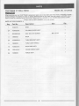
Alwaysorderby PARTNUMBER,not by keynumber
A
FOR
SCHEMATIC
PARTS
LIST
Size
QtY
Part No.
Description
10300105
BASE
2A
10300202A2
ASS'Y
COLUMNHOLDER
3
26018BD490
HEX.SOC.SETSCREW
4
13902202
RACK
1
5A
10300603411
ASS'Y
TABLEBRACKET
1
6
10602003
TABLELOCKHANDLE
1
7A
10302301A1
RACKRINGASS'Y
1
8A
13901001A1
ASS'Y
CRANKHANDLE
1
9A
10399202
FENCEASS'Y
1
Key
1
.
1
M8x1.25-25
::.L::::.':.:i::
4
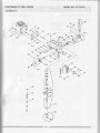
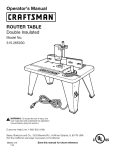
CRAFTSMAN
12" DRILLPRESS
MODEL
NO.137.219120
A
SGHEMATIC
"^\,2
6\
IK
w\r\-..
[
./- i\-':
YU\
:
\n,1
\U
l
I
,)i
I
/t
q-
I
^^ -:
-/-z
r\J
\-'---^
'
MODELNO.137.219120
CRAFTSMAN
12'' DRILLPRESS
B
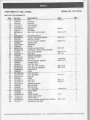
LISTFORSCHEMATIC
PARTS
Part No.
11
12
13A
14A
15
16
17
18
19
10301004
10201201
2137132108
10305602A1
2701F8D106
10361701
2602BBLAC7
N/A
2898D08G24
SETBOLT
POINTER
CHUCKASS'Y
QUILLASS'Y
HEXNUT
SETRING
HEX.SOC.HD.CAPBOLT
21
22
23
24
25
26
27
28
29
10312704
266888DA24
10308805
2805U5HN16
10384902
2668BZDM3
25O4MZCOO5
10305401
2701F8D113
SWITCHCOVER
CR.RE.PANHD.SCREW
SWITCHBOX
TERMINAL
SCALE
HD SCREW
CR.RE.PAN
TOOTHLOCKWASHER
EXTERNAL
QUILLSETSCREW
HEX.NUT
31A
92
33
u
35
36
37
38
39
1O3O5OO1A2
2701Q2D611
266888DA24
10808301
1O6O42M
2603881452
2603881A52
2536M88623
13902503
SPRINGCAPASS'Y
HEX.NUT
CR.RE.PANHD.SCREW
CLAMP-CORD
SHIFTERBOLT
HEX.SOC.SETSCREW
HEX.SOC.SETSCREW
SPRINGPIN
HEAD
41
42A
43
44
45
46
47
48
49
2501MBDN0B
8220pc1104
13916403
270'!FBD113
27o1FBD11o
25O2ABC41O
10303401
10303202
2501NNVN11
FLATWASHER
MOTOR
LABEL
HEX'NUT
H E X 'N U T
SPRINGWASHER
MOTORBASE
MOTORROD
FLATWASHER
51
52
53A
54A
55
56
10316208
2658M2DU36
10304301A4
10303825A1
2&I1BBDA39
10511201
LABEL
DRIVESCREW
HANDLEBARASS'Y
FEED SHAFT
CR.RE.ROUNDWASHERHD.SCREW
CHUCKKEYHOLDER
M6X1.0
M 5x 0 . 8 - 1 6
't
ROCKERSWITCH
M5x0'8-12
M5x0.8-8
M8x125-18
M8x1'25
1/2x20UNF
M8x 0 8-12
M8x1'25-8
M8x1'25-8
a8x16'2'5
M8x1'25
Mloxl'S
24
1
3
1
1
1
2
2
1
1
1
2
1
1
2
2
1
2
1
B
1
1
4
1
2
1
1t4x3t4-3t16
4
2.3-5
1
4
1
M6*1.0-12
1
1
CRAFTSMAN
12" DRILLPRESS
MODELNO.{37.219120
SCHEMATICB
_/
t2
11
10
25
w
MODELNO.137.219120
CRAFTSMAN
12" DRILLPRESS
PARTSLISTFORSCHEMATIC
C
Size
ety
WRENCHHEX
4-64
1
2138MB1703
WRENCHHEX
3-57
1
59
28078806H2
POWERCABLE
1
60
13916905
LABEL
1
61
2801A8RF04
STRAINRELIEF
2
62
2572ARK340
V-BELT
1
63
10306901
PULLEYSETNUT
1
64
10307005
SPINDLE
PULLEY
1
65A
10306512A1
DRIVINGSLEEVEASS'Y
1
66
13916602
LABEL
1
57
2138M8L704
58
67
264188DA39
CR.RE.ROUNDHD.SCREW
68
10208302
CLAMP-CORD
3
69
26688BDA23
CR.RE.PANHD.SCREW
3
70A
1030790842
MOTORPULLEYASS'Y
1
71
2571MNC307
PARALLEL
KEY
1
13909002A1
PULLEYCOVERASS'Y
1
72A
26 i:Wfw*{*!
M6X1.0-12
4
liloDELNO.137.219120
70A
i
(
- \.jT-_-
iI
69
65A
66'
68
87
./
60
{
in your own.home"'
For repairof majorbrandappliances
no matterwho madeit, no matterwho sold it!
i
il'f
1'800-4-MY'HOMESM mvti*e,davornisht
(1-800-469-4663)
www.sears.com
andelectronics
suchasvacuufis,lawnequipment
To bringin products
RepalrCenter'
&
Parts
Sears
of yournearest
forrepair,iatttbrtnetocation
davornpht
envtime,
1'800'488-1222
www.s€ars.com
andowne/smanuals
parts,accessories
Forthereplacement
callsearsPartsDirectst
thatyouneed.todo-it-yourself,
csr'
1'800'366'PART e'''' - 11P'm'
(1'800'36&72781
l'!
TdaYsaweek
www-sears.com/Partsdirect
or inquireabouta SearsServiceAgreement:
To purchase
1-800-827-6655
7 a.m.'5 P.m.CST'Mon'- Sat'
enfrangais:
AuCanada
Pourseruice
1-877.LE.FOYER*
Para pedirserviciode reparaci6na domicilio,
y parabrdenarpiezascon entregaa domicilio:
tu
l-8s8-su-HoGAR
(1-877-s336937)
(1-88&784-6427)
sEl\Fls
9t5'!.
Robu€t.nd
Co'
HomeCentral-
and Co'
@ Registered Trademalk/il Tradsmark ol Sears,Ro€buck
and co'
@ Marca RegistradalilMarca de Fabrica de Sears'Ro€buck
FULL ONEYEARWARFANTY
y€ar f|o r the dato ot putchase, Sears
It his oroduct hils due to a det€ct in materia! or workmanship within one
will repairit tree of charg€.
Cmtact a S€ars Se|ice Center for repair'
lor 90 drys ttom tho dat€ of
lf hb Droductis used 19rcommerci4 or rental purpose3, this wananty appliesonly
purchaso.
which vaty frotn stale to slal€'
This wananty gives you spccifc legal rights. and you may atso have othef rights
S.!r3. Roebuck and Co., D€Pt.817 WA, tloftm.n €!t8tet' lL 60179
cln$nbt(Iruoet
ANo
gosta|r3rrfii6nEp63entasedetbctosd€mat
rialobbfi.zciind€ntmd€lptim.fdoagattirdthhdla&compra'
'Saer!
la EpatarAsit cosb al$t|o.
Co.rbchrlaconun Centrode S€rviio de S€at! garah t€9arad6n.
potlo3paim€tls90 ' patli?
s esa hqramienase usapaa frnescomeaialero paraalqd€t, 6!a garartfaseaplcasdlo
& h hdra de co.nPa
lreriatlda un
Elb granda le obrge der€drostegal€s63p€€itie y amtriehpodrh u$?d teno.otos delld|oe $Ie
csbdoa ofo
ScaE, Roebuck end Co., Dept. 817 WA, Hotfman Ertat .' lL 50179
11/2000