1
EN
Digital timer thermosatat
iSense
Installation and
Service Manual
120666-AG
Contents
1
Preface ........................................................................................................4
1.1
2
3
General ..................................................................4
Location of the installation ........................................................................5
2.1
Position of the regulator ......................................5
2.2
Installation and connection .................................6
2.3
Location of the outside sensor ...........................7
2.4
Room sensor .........................................................7
Start-up ........................................................................................................8
3.1
Fitted control unit .................................................8
3.1.1
3.1.2
4
3.2
Setting language, time and date ..........................9
3.3
Default setting .......................................................9
Setting .......................................................................................................11
4.1
Changing the settings ........................................11
4.1.1
4.1.2
4.1.3
4.1.4
4.2
4.3
Defining or modifying a timer program ..................11
Setting continuous temperatures ..........................12
Setting the holiday mode .......................................13
Group control ........................................................13
Operating the controller .....................................14
4.2.1
4.2.2
4.2.3
4.2.4
4.2.5
Selecting a program ..............................................14
Temporarily changing the temperature .................14
Fireplace mode .....................................................15
Information ............................................................15
Groups ..................................................................15
Changing usage settings ...................................16
4.3.1
4.3.2
4.3.3
4.3.4
4.3.5
4.3.6
4.3.7
4.3.8
4.3.9
1
Meaning of the symbols on the display ...................8
Functions of the keys ..............................................9
Setting the display .................................................16
Setting button locking ............................................16
Setting the language .............................................16
Setting the user level .............................................16
Resetting factory settings ......................................17
Calibration .............................................................17
Restoring a connection with the base station (Only
controller RF) ........................................................17
Connecting extra RF sensors (Only controller
RF) ........................................................................17
Setting the time and date ......................................17
030211 - 120666-AG
Contents
4.3.10
4.3.11
4.3.12
4.3.13
4.3.14
4.3.15
5
6
Selecting the control strategy .................................................................22
5.1
Six control strategies .........................................22
5.2
Setting the control strategy ...............................23
5.3
Specific settings for weather-compensated
control ..................................................................24
5.4
Heating curve - For example ..............................25
Installer settings .......................................................................................26
6.1
Telephone number for service messages and
failure signals ......................................................26
6.2
Service messages on or off ...............................26
6.3
PIN code for menus for the installer and
system .................................................................26
6.4
Digital input .........................................................26
6.4.1
6.4.2
6.5
7
8
2
Comfort correction .................................................18
Legionella function ................................................18
Controlling the tap water temperature ...................18
Central heating settings ........................................20
Frost protection - System ......................................21
Frost protection - Room ........................................21
Operation ..............................................................26
Examples ..............................................................27
Boiler Setting ......................................................29
Messages ..................................................................................................30
7.1
Error messages ...................................................30
7.2
Maintenance message ........................................31
7.3
Incidents and solutions ......................................31
Menu / Technical data ..............................................................................33
8.1
Menu structure ....................................................33
8.2
Technical characteristics ...................................35
030211 - 120666-AG
3
030211 - 120666-AG
iSense
1. Preface
1
Preface
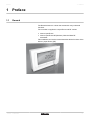
1.1
General
The Remeha iSense is a timer thermostat with many enhanced
functions.
The controller is supplied in a OpenTherm and RF variant:
4 iSense OpenTherm.
4 iSense OpenTherm RF(Wireless). With the iBase RF
transmitter.
This installation and service manual describes all the functions of the
iSense. (OpenTherm) (RF)
030211 - 120666-AG
4
2. Location of the installation
iSense
2
Location of the installation
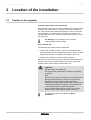
2.1
Position of the regulator
Controller OpenTherm and controller RF
The controller is set to room control by default. The controller can be
installed on an inside wall or in a boiler, if the boiler is suitable for
this. This means that the inside temperature is used to control the
central heating. It is therefore best to locate the controller on an
internal wall in the room in which you spend the most time, such as
the living room.
For Germany: The controller is set to weathercompensated control by default.
Only controller RF
The following also applies for the controller RF:
4 Position the controller at least 1 metres from equipment with
electromagnetic emissions (Washing machines, dryers, cordless
telephones, televisions, computers, microwave ovens etc).
4 Position the controller so that it has good reception.
Take account of the fact that objects containing metal will affect the
reception. These include steel-reinforced concrete, mirrors and
windows with a metal coating, insulation films, etc.
CAUTION
Wireless range of controller RF
The range of the controller RF in buildings is generally
30 metres.
Note!
This value is purely an indication! The actual range of the
RF signal depends heavily on the local environment.
Remember that the number of walls and ceilings
(regardless of whether they contain metal or not) can have
a considerable impact on reception. Other objects that
contain metal may also impact the reception.
These include steel-reinforced concrete, mirrors and
windows with a metal coating, insulation films, etc.
The signal strength can be viewed via Menu >
Information.
5
030211 - 120666-AG
2. Location of the installation
iSense
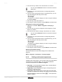
2.2
Installation and connection
Before you can connect the controller, you must first:
4 Adjust the boiler so that it can be connected to a OpenTherm
controller. See the installation and service manual for the boiler.
4 Shut down the boiler.
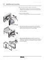
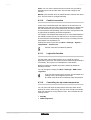
To do this, proceed as follows:
1. Open the housing by pulling the front and the base plate apart.
T001046-D
2. Attach the base plate to the wall using the screws and plugs
supplied. Ensure that the OpenTherm connecting wires for the
boiler are poking through the hole in the base plate.
2x
2x
2
3
4
2x
1
T001035-C
OT
Digi
3. (Only controller OpenTherm) Connect the controller to the
OpenTherm connection of the boiler, and to the OT connection of
the controller. OpenTherm is not sensitive to polarity. The wires
are interchangeable.
OT
T001036-D
030211 - 120666-AG
6
iSense
2. Location of the installation
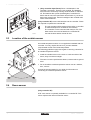
4. (Only controller OpenTherm) Place 3 AA batteries in the
controller if necessary. These are not supplied. The batteries
ensure that the clock keeps running when the boiler is switched
off. The batteries also power the backlights of controllers for
boilers that do not have OpenTherm Smart Power. If you have a
boiler with Smart Power, then the backlight of the controller also
works without batteries.
(Only controller RF) Insert 3 AA batteries into the controller. These
are required to operate the controller RF.
The set programs will be retained if the boiler or controller
is switched off (Even if no batteries are inserted).
The controller is now connected and ready for use. The
base station must now be fitted for the controller RF.
Consult the base station manual for this.
T001042-C
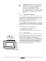
2.3
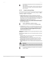
Location of the outside sensor
An outside temperature sensor is not supplied as standard with the
controller. You only require this sensor if you want weathercompensated control of the inside temperature.
The following guidelines apply with regard to choosing a location for
an outside temperature sensor:
4 Install the outside sensor on the north or north-west side of the
home, away from direct sunlight.
>2
4 The sensor must be positioned at least 2,5 metres above ground
level.
,5m
4 Do not install the outside temperature sensor next to a window,
door, vent etc
Consult the documentation for your boiler for information on
connecting an outside temperature sensor.
T001043-B
2.4
Room sensor
(Only controller RF)
A RF room sensor is optionally available for a controller RF. This
sensor replaces the internal controller sensor.
7
030211 - 120666-AG
iSense
3. Start-up
3
Start-up
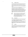
3.1
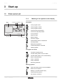
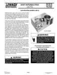
Fitted control unit
3.1.1.
Textbox
menus
Pictograms Temperature Time
Menu
Mode button A
Program
Mode button B
T001034-04-A
Meaning of the symbols on the display
Pictograms
s
Clock program active
u
Clock program A active
t
Clock program B active
!
Continuous day temperature
z
Continuous night temperature
]
Frost protection
{
Summer mode
E
Manual setting
x
Vacation program
T
DHW standby function switched off
\
Set temperature
H
Measured temperature
Z
Outside temperature measured
I
Heating System
Pictograms not shown
D
Controller requesting heat
IN
Central heating boiler on for hot water
ID
Central heating boiler on for central heating
d
Button locking enabled
p
Group 1 selected
q
Group 2 selected
r
Electricity production
Warning symbols
030211 - 120666-AG
e
Check the water pressure in the installation
?
Boiler service required
v
Battery in controller almost empty
c
General warning symbol
w
No wireless connection
8
iSense
3. Start-up
3.1.2.
Functions of the keys
The controller is menu-controlled, which means it is very simple to
operate.
It only has three buttons.
4
4
4
A
B
4
C
4
T000059-B
3.2
The function of button A and button B depends on the
task you are carrying out.
The function is shown in the display immediately
above the buttons.
Button C is a push-turn button.
You press it to confirm choices (Such as menu
selections).
By turning it you can perform various tasks such as
scrolling through menus or changing values such as
(Temperature Time Date Language).
Setting language, time and date
When you connect the controller, the language selection menu
appears.
1. Select the desired language by pressing button C, and then press
button C to confirm.
2. Follow the instructions on the display to select the time, year,
month and day.
The controller is now connected and ready for use. The default clock
program is activated after installation. ¼ "Default setting", page
9
The temperature is now controlled by this clock program.
The controller automatically switches between summer
and winter time.
3.3
Default setting
The controller is set to room control by default (Central heating is
controlled on the basis of the inside temperature). Weathercompensated control of the boiler is also possible (on the basis of the
outside temperature).
Programme schedule
The default clock program sets the temperature daily as follows:
4 06.00 - 19.00: 20℃
4 19.00 - 23.00: 21℃
4 23.00 - 06.00: 15℃ + T
9
030211 - 120666-AG
iSense
3. Start-up
You can of course adapt the clock programs to your own
requirements. ¼ "Defining or modifying a timer program", page
11
030211 - 120666-AG
10
iSense
4. Setting
4
Setting
4.1
Changing the settings
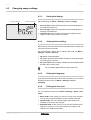
4.1.1.
Defining or modifying a timer program
Time
MO
7:00
20℃ 20℃ 20℃ 20℃ 20℃
9:00
15℃ 15℃
TU
WE
TH
FR
SA
SU
15℃ 15℃ 20℃ 20℃
11:00
13:00
15℃
15:00
17:00
19:00 21℃
21℃ 21℃ 21℃ 21℃
21:00
21℃
23:00 15℃ 15℃ 15℃
15℃
0:00
15℃ 15℃ 15℃
The timing program automatically controls the room temperature on
the basis of set time intervals and can be separately regulated for
each day of the week. You can adjust the default clock program or
enter a completely new program.
The controller starts pre-heating prior to the set time by
default. This allows the room to reach the desired
temperature at the correct time. To change the pre-heating
setting ¼ "Central heating settings", page 20.
Setting the clock program indirectly determines when DHW
standby is active ¼ "Controlling the tap water
temperature", page 18.
Summary table
It is useful to draw up your own overview with switch times (What
temperature does it need to be and when in your home ?).
This of course depends on who is at home and when, and what time
you get up, etc. You can set 6 switch times per day. See the table on
this page.
Creating a new clock program
1. Select in the controller: Menu > Program > Clock prog. > New.
2. Select an initial program if appropriate (Home in daytime, Home
midweek or Home at weekends). You can now create your own
clock program based on this program. Press button C to confirm.
3. Go to the day you want to set the clock program for. Press button
C to confirm.
11
030211 - 120666-AG
4. Setting
iSense
4. Go to the time you want to set. Press button C to confirm
You can use the Remove button to remove the selected
switch time.
5. Use button C to set the time and the corresponding desired
temperature.
6. Once you have set all switch times for a particular day, you can
copy the settings for that day to other days:
- Go to the day.
- Press Copy
- Use button C to select the day(s) you want to copy the settings
to, and press Save
7. Go to the day. Then press button C.
8. Go to step 3 to set the next day. Or press Back to close this menu.
Changing an existing clock program
1. Select in the controller: Menu > Program > Clock prog. >
Change.
2. Go to the day you want to change the clock program for. Press
button C to confirm.
3. Go to the time you want to change. Press button C to confirm.
You can use the Remove button to remove the selected
switch time.
4. Use button C to set the time and the corresponding desired
temperature.
5. Once you have set all switch times for a particular day, you can
copy the settings for that day to other days:
- Go to the day.
- Press Copy
- Use button C to select the day(s) you want to copy the settings
to, and press Save
6. Go to the day. Then press button C.
7. Go to step 2 to set the next day. Or press Back to close this menu.
Restoring the default settings
Proceed as follows to restore the settings for the default clock
program:
Menu > Program > Clock prog. > Factory program.
4.1.2.
Setting continuous temperatures
Instead of the clock program, you can also set the room temperature
continuously to a particular value. You can set three different
continuous temperatures via: Menu > Program
4 Day temp.: room temperature during the day, corresponding to
the: Continuous day program.
4 Night temp.: Room temperature at night, corresponding to the:
Continuous night program.
4 Frost temp.: Room temperature to protect the room where the
controller is installed from freezing. This setting comes under the
program: Frost. For further information ¼ "Frost protection System", page 21.
030211 - 120666-AG
12
iSense
4. Setting
The Night temp setting is also used in combination with
the functions Day temperature limit, Night temperature
limit ¼ "Specific settings for weather-compensated
control", page 24 DHW standby function ¼
"Controlling the tap water temperature", page 18.
If the set room temperature is below the value set at Night
temp., Then the DHW standby function is switched off by
default. ¼ "Controlling the tap water temperature",
page 18
4.1.3.
Setting the holiday mode
It can be useful to set a holiday program if you are away from home
for some time. This ensures a constant temperature in your home for
the period you set. You set the temperature yourself.
A holiday program automatically takes effect from 0:00 hours on the
start date. And ends at the start of the end date.
The symbol x appears on the display. This program is switched off
and removed once the set period has ended.You can set a maximum
of 16 holiday programs. You do this via: Menu > Program > Holiday
prog.:
4 Select View to look at the set holiday programs.
4 Select Change to change or remove programs.
4 Select Enter to add a new program.
4 Select Desired temp to set the desired constant temperature.
4.1.4.
1 2
Group control
Using the c-Mix, the controller can control 2 groups. Both groups can
have their own program selection and control strategy. You do this
via: Menu > Settings > System > CH system > Zoning
The default setting is No groups. The option 1&2 separately can be
used to assign each group its own program. The symbol o appears
in the standard display. Pressing the push-turn button allows you to
switch between the operation of group 1 and 2. If 2 follows 1 is
selected, both groups are assigned their own control strategy, but
group 2 will follow the program for group 1.
T900039-A
13
030211 - 120666-AG
iSense
4.2
4. Setting
Operating the controller
4.2.1.
Selecting a program
You can select one of the following programs via Program in the main
display:
4 Clock prog.: The central heating temperature is controlled by the
program you have set.
4 Continuous day program: The temperature remains constant at
the day temperature you have set.
4 Continuous night program: The temperature remains constant
at the night temperature you have set.
4 Frost: The temperature remains constant at the frost protection
temperature you have set. DHW standby is switched off for this
program.
4 Continuous summer: The temperature remains constant at the
night temperature you have set. Whereby the tap water is on
standby between 06:00 and 23:00. (which means that you will get
hot water more quickly).
For DHW standby ¼ "Controlling the tap water
temperature", page 18
4.2.2.
Temporarily changing the temperature
You can temporarily switch off a selected clock program or continuous
program at any time by setting the temperature manually.
1. Turn button C from the main display to set a new temperature.
2. Press Adjust time if you want to set an end time for the manually
selected temperature. Select this time using push-turn button C.
3. Press Adjust date if you want to set an end date for the manually
selected temperature. Select this date using push-turn button C.
4. Press button C to return to the main menu. Or alternatively wait
5 seconds until the controller automatically returns to the main
menu.
If you do not select an end time and a clock program was
active, that clock program will become active again at the
next switch point. Manual operation will then be switched
off.
Press the Next program button to cancel the manual
temperature change.
030211 - 120666-AG
14
iSense
4. Setting
4.2.3.
Fireplace mode
Once the temperature has reached the desired level in the room
where the controller is located, the central heating switches off. This
may be inconvenient if you have an open fire. Or if a lot of people are
present. Other rooms in the house are also no longer heated in this
situation.
In order to ensure other rooms are still heated, you can switch on the
fireplace mode. You do this via the Program button.
This switches off the built-in room sensor in the controller. The
temperature of the central heating water at that point is then
maintained. If it becomes too cold or too hot in the other rooms, you
can increase or decrease the room temperature there using push-turn
button C on the controller. This increases or decreases the central
heating water temperature.You can fit thermostat valves to the
radiators in order to control the temperatures individually in these
rooms.
Fireplace mode should only be activated if the controller
uses the room temperature to control the temperature.
To prevent the temperature in the room where the
controller is located becoming too high. It is recommended
that you close the radiator valves there.
The controller switches to weather-compensated control if
the outside temperature sensor is used.
4.2.4.
Information
You can request operating information about your central heating
system via: Menu > Information. Such as the water pressure in the
central heating system and various temperatures.
The information available depends on your central heating unit. The
Basic and Normal modes do not show all information categories
which are available. Select More information to make all information
available.
4.2.5.
Groups
When the controller is set to control 2 groups separately, a o icon is
displayed on the standard screen. The number in the icon shows
which group is selected for control. The group can be changed by
pressing button C once.
15
030211 - 120666-AG
4. Setting
iSense
4.3
Changing usage settings
4.3.1.
Large information line
Small information line
Setting the display
Set the following via: Menu > Settings > Users > Display
4 Info line small: Select what information should be displayed on
the small information line.
4 Info line large: Select what information should be displayed on
the large information line.
4 Light time-out: Set how many seconds the backlight should
remain on after the last button is touched.
T001037-04-C
4.3.2.
Setting button locking
Button locking ensures that the buttons are locked if the controller has
not been used for 30 seconds.
You can set button locking, with or without a PIN code, via: Menu >
Settings > Users > Key lock
4 Off: Button locking disabled.
4 On: Button locking enabled. Button locking can be enabled again
by pressing button C2 time.
4 On + pin code: Button locking is enabled and can be disabled with
the PIN code you enter here.
You can always disable button locking with 0012.
4.3.3.
Setting the language
If you have the international version of the controller, you can set the
language for the menus via: Menu > Settings > Users >
Language.
4.3.4.
Setting the user level
You can select the user level via: Menu > Settings > Users > User
mode.
4 Basic mode: In this mode, you can not use any clock programs.
You can only set the temperature on the controller manually.
4 Normal mode: This is the default setting. Most options are
available, such as the clock program.
4 Extended mode: In this mode, you can use two standard clock
programs, A and B. You can also change more settings and
request more detailed information.
030211 - 120666-AG
16
iSense
4. Setting
Some settings can only be changed in the mode Extended
mode. The settings you create remain enabled in the
modes Basic mode and Normal mode.
4.3.5.
Resetting factory settings
You can reset all settings, including the clock program, to the works
setting via: Menu > Settings > Users > Reset
4.3.6.
Calibration
You can adjust the measuring value from the inside and outside
sensors via: Menu > Settings > Users > Calibration. This can be
useful if the measured temperatures do not correspond to what you
are used to.
Imagine that the measured temperature is 0,5℃ higher than what you
are used to. You can then enter an adjustment here of -0,5℃.
4.3.7.
Restoring a connection with the base
station (Only controller RF)
When the controller RF or the base station is replaced, you must
restore the connection. To do this, proceed as follows:
1. Put the base station in connection mode. Consult the base station
manual for this.
2. Select in the controller: Menu > Settings > Users >
Connection > Base station.
After a few seconds, the connection is restored.
4.3.8.
Connecting extra RF sensors (Only
controller RF)
1. Set the RF sensor to be connected to connection mode. (Refer to
the documentation for the relevant sensor).
2. In controller RF, select: Menu > Settings > Users >
Connection. Select the correct sensor and press connect. After
a few seconds, the connection is restored.
4.3.9.
Setting the time and date
Set the correct date and time as follows: Menu > Settings > Date/
time.
4 Set time
4 Set date
4 Summer time:
Europe: The controller automatically switches between summer and
winter time.
17
030211 - 120666-AG
4. Setting
iSense
Other: You can set the start and end of summer time yourself by
indicating the month and the week. The time will change on the
Sunday.
Manual: The controller does not switch between summer and winter
time. The time must be changed manually.
4.3.10.
Comfort correction
It feels more comfortable when the radiators in the home are hot
(Between 50°C and 90°C).The perceived temperature is higher than
the real temperature due to the radiant heat. Comfort correction
ensures that the central heating does not heat to a temperature that
is higher than the desired perceived temperature.
For example: The desired temperature is 21℃. The radiant heat from
the radiators means that 20,7℃ feels like 21℃. Comfort correction
ensures that the central heating does not carry on heating once the
temperature has reached 20,7℃.
Change the comfort correction via: Menu > Settings > System >
Temperature > Comfort corr.
Comfort correction is enabled by default.
4.3.11.
Legionella function
The tap water can be heated to 65℃ once a week to prevent
legionella in your boiler. This measure can be used for external boilers
if necessary. This option is not available for combi-boilers.
When this setting is enabled, tap water is heated by default on
Mondays at 02:00.
You can change the setting via: Menu > Settings > DHW > AntiLegionella
To ensure this function works correctly, check whether any
settings have to be changed on the boiler.
The boiler must allow an increased tap water temperature.
4.3.12.
Controlling the tap water temperature
You can set if and when the temperature of the tap water can be
lowered, in order to save energy. This can occur at night, for example,
when the demand for hot tap water is lower. The controller has two
settings for this:
4 Standby
4 DHW temperature
030211 - 120666-AG
18
iSense
4. Setting
4
Both functions are active simultaneously.
4
The T icon is shown in the display when DHW
standby is switched off.
Time Desired room temperature
07:00 20℃
09:00 15℃ T
11:00
13:00
15:00
17:00
19:00 21℃
21:00
23:00 15℃ T
00:00
DHW standby
The combi-boiler pre-heats periodically in order to be able to meet the
demand for hot tap water quickly. You can set this option via:
Menu > Settings > DHW > Standby
You can choose from the following options:
4 Continuous off: The combi-boiler does not keep itself hot. Select
this option for maximum energy saving.
4 Continuous on: The combi-boiler keeps itself hot continuously.
Select this option for optimum comfort.
4 Night temp off (T appears on the display): The boiler is not preheated if the desired room temperature is the same as or lower
than the night temperature, which is set via: Menu > Program >
Night temp. For example: If the Night temp setting is on 15℃,
for example, the tap water will not be kept hot for certain periods.
Select the Night off option for energy saving during the night.
Boilers respond differently to this function. Some do
provide hot water, but take longer to get up to
temperature. Others only provide the heat that is still
present. For example in a boiler, and the water
subsequently becomes cold.
See the installation and service manual for the boiler.
Domestic water temperature
1. Select in the controller: Menu > Settings > DHW > DHW
temperature
2. You can choose from the following options:
- Temperature: Select the temperature that the hot tap water must
have continuously.
- Clock prog.: Use a clock program to determine the temperature of
the tap water. Setting this clock program is virtually identical to setting
a clock program for the desired room temperature. ¼ "Defining
or modifying a timer program", page 11.
19
030211 - 120666-AG
iSense
4. Setting
The maximum temperature that can be set depends on the
boiler settings.
When setting a clock program, start this an hour before you
require the first hot water. This gives the boiler sufficient
time to heat up.
4.3.13.
Central heating settings
You can set a number of specific central heating settings via: Menu
> Settings > System > CH system:
4 Pump control: When this option is switched on, the pump
switches off when there is no demand for hot water. This means
the pump runs for less time (saving electricity). As the pump is off
if the boiler is not on, it may take a few minutes for a radiator to
actually fill with hot water when you turn it on.
4 Heating rate: This allows you to determine how quickly or slowly
the controller responds. This parameter affects the pre-heating
and the control response.
Set this to Slowest for underfloor heating.
For the eVita, we recommend the setting Extra Slow.
4 Cooling rate: This allows you to indicate how quickly the home
cools or how well your home is insulated. The better the insulation,
the slower the home cools down. This parameter affects the
control strategies RTC and OTC+comfort. And the off-periods
between the burner coming on.
Cooling rate > Slowest: Gives long off-periods between the burner
coming on.
Cooling rate > Fastest: Gives short off-periods between the burner
coming on.
4 Max. pre-heat: The maximum time before a switch point that preheating can begin (Time in minutes).
4 Min. CH temp.: Minimum desired temperature of the central
heating water. This setting is particularly useful for convectors.
4 Max. CH temp.: Maximum temperature of the control for the
central heating water. This is not the maximum temperature of the
boiler.
CAUTION
If this concerns a safety function, this must be set on the
boiler.
The engineer installing the controller can set a number of
specific settings.
030211 - 120666-AG
20
4. Setting
iSense
4.3.14.
Frost protection - System
You can use the frost protection system option to protect radiators in
frost-sensitive rooms against freezing. For example: The temperature
in the home at night does not drop below 19℃, which means the pump
does not come on. The radiator in the annexe, which gets colder, runs
the risk of freezing.
The frost protection system option is automatically switched on if you
have an outside sensor. The outside temperature at which this
switches on can be set via: Menu > Settings > System >
Temperature > Frost protection.
This value is set to -10℃ by default. The pump then starts
at -10.5℃ and stops again at -9.5℃
4.3.15.
Frost protection - Room
Use "room" frost protection to protect the room where the controller
is located from frost. This does not require an outside sensor.
The minimum room temperature for frost protection is set at 6℃. You
can change this temperature via: Menu > Program > Frost temp..
Activate "room" frost protection via: Program > Frost.
Any radiator valves present in the reference room must be
fully opened.
21
030211 - 120666-AG
5. Selecting the control strategy
iSense
5
Selecting the control strategy
5.1
Six control strategies
The controller can be used as a weather compensator or as a room
thermostat (Room control). Six control strategies are available for
this.
1 RTC: (Modulating control) Room control
The control measures the room temperature in the reference room
(the room where the thermostat is located). The required flow
temperature based on an intelligent control system is now
calculated. The boiler works by modulating. It controls the output on
the basis of the flow temperature and return temperature of the
water. This allows it to operate as efficiently as possible. With as
constant a water temperature as possible.
Room control can be used anywhere. Unless you do not
want a single reference room to determine the temperature
for all the other rooms.
2 OTC: Control as a function of the temperature
The control measures the outside temperature with an outside
temperature sensor. The controller has a programmed heating
curve. Based on the outside temperature, the flow temperature is
determined with the help of the heating curve.
The heating curve must be chosen so that the least favourable room
can be heated efficiently, even when the outside temperatures are
very low.
The measured inside temperature does not affect the control of the
boiler. The desired inside temperature is only achieved with a
correctly programmed heating curve and a correctly designed
system.
Normal outside conditions are also important. Direct sunlight or a
strong northerly wind mean lower or higher heating requirements
respectively. This has no influence on the supply of heat. This is why
weather-compensated control alone is insufficient. and adjustments
have to be made in each room, using thermostat valves.
3 OTC + RT: Weather-compensated with the effect of the room
temperature
The basis of this control strategy is the same as weathercompensated control. The heating curve must therefore be correctly
entered. The heating curve is also shifted when the measured room
temperature deviates from the desired room temperature. The degree
of shift is influenced by the RT effect setting. ¼ "Specific settings
for weather-compensated control", page 24
The advantage of this control is that desired changes in room
temperature can be anticipated quickly. The boiler will remain off for
longer for desired downward changes in room temperature. This is
good for the energy consumption.
030211 - 120666-AG
22
iSense
5. Selecting the control strategy
Adjustments are not needed in the room where the controller is
located. Any radiator valves present in the reference room must be
fully opened.
4 OTC + C-RT: Weather-compensated with comfort function
The basis of this control strategy is the same as weathercompensated control. The heating curve must therefore be correctly
entered. The heating curve is also shifted on the basis of a room
temperature that is calculated (therefore not measured). The outside
temperature, the heat up rate and the cooling rate influence this.
The degree of shift is influenced by the RT effect setting. ¼
"Specific settings for weather-compensated control", page 24
The advantage of this control is that desired changes in room
temperature can be anticipated quickly. Without the controller having
to be located in the reference room.
The boiler will remain off for longer for desired downward changes in
room temperature. This is good for the energy consumption.
5 OTC/RTC ECO: Weather-compensated with comfort function
The OTC control strategy is used where the desired room
temperature is higher than the night temperature. Night temperature
is set via: Menu > Program > Night temp.
The relevant settings must therefore be set. The RTC control strategy
is used where the desired room temperature is the same as or lower
than the night temperature.
The controller must then be located in a room which is representative
for room temperature measurement during the night. This control
strategy prevents the boiler from being switched on unnecessarily
during the night.
6 RTC + Limit
Room control with heating curve as limit. Same as control strategy
1, but the heating curve is used as max boiler temperature. (External
sensor required).
The RTC control does not have its full temperature control
range available due to the heating curve limit. As a result,
it may take longer to heat up.
5.2
Setting the control strategy
The controller lets you use the room control and/or weathercompensated control strategies in various ways. You can select one
of the controls, described in paragraph 5.1 via: Menu > Settings >
System > Control settings.
23
030211 - 120666-AG
iSense
5.3
5. Selecting the control strategy
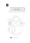
Specific settings for weather-compensated control
If you have opted for a weather-compensated control strategy, a
number of extra settings are available via: Menu > Settings >
System > OTC settings > Heating curve
Increased room temperature during the day
Desired room temperature of 20ºC during the day
Desired room temperature of 15ºC during the night
4 Base outside: Outside temperature base point.
Climate point
4 Base flowtemp: Flow temperature base point.
100
90
4 Climate outside: Flow temperature climate point.
80
4 Curvature: Degree of curvature of the heating curve, depending
on your central heating system. Select the relevant type of
heaters: Underfloor heating, radiators or convectors.
70
Boiler temperature (ºC)
60
50
40
Base point
30
20
10
0
-15
-5
0
Outside temperature (ºC)
5
15
25
T001038-04-A
030211 - 120666-AG
The heating curve is based on a desired room temperature
of 20℃. By increasing the desired room temperature, the
heating curve shifts upwards. The degree of shift is
influenced by the RT effect setting.
4 RT effect: Effect of room temperature on the shift in the heating
curve.
4 Heat limit day: Outside temperature above which the central
heating is switched off during the day. The day temperature limit
is relevant when the desired room temperature is higher than the
night temperature which has been set via: Menu > Program >
Night temp.
4 Heat limit night: Outside temperature above which the central
heating is switched off during the night. The night temperature limit
is relevant when the desired room temperature is the same as or
lower than the night temperature that has been set via: Menu >
Program > Night temp.
24
5. Selecting the control strategy
5.4
iSense
Heating curve - For example
The settings for the heating curve are highly dependent on the design
of the central heating system and the home. This means that no clear
advice can be given on this matter. Use the tables below as a basic
setting if you do not know the design information. The heating curve
can be optimised during use. The heating curve also shifts upwards
or downwards when the temperature is increased or decreased.
Heating by radiators
Building insulation
Very good Good Average Less good Poor
RT effect
4
5
5
6
6
Base outside
16
17
18
19
20
Base flowtemp
20
20
20
20
20
Climate outside
-10
-10
-10
-10
-10
Climate flowtemp
70
75
80
85
90
Underfloor heating
Building insulation
Very good Good Average Less good Poor
RT effect
1
2
3
3
4
Base outside
16
17
18
19
20
Base flowtemp
20
20
20
20
20
Climate outside
-10
-10
-10
-10
-10
Climate flowtemp
40
40
40
40
40
Air heating
Convectors
Building insulation
Very good Good Average Less good Poor
RT effect
2
3
3
4
4
Base outside
16
17
18
19
20
Base flowtemp
50
50
50
50
50
Climate outside
-10
-10
-10
-10
-10
75
80
85
90
Climate flowtemp 70
25
030211 - 120666-AG
6. Installer settings
iSense
6
Installer settings
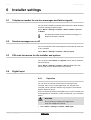
6.1
Telephone number for service messages and failure signals
You can enter a telephone number to be shown if the boiler displays
a service message or failure signal.
Select: Menu > Settings > Installer > Phone number > Service
or Repair
No telephone number is shown with the message if no
telephone number is entered.
6.2
Service messages on or off
You can set whether service messages from the boiler can be shown
on the controller.
Select: Menu > Settings > Installer > Service report.
6.3
PIN code for menus for the installer and system
You can protect the Installer and System menus with a permanent
PIN code (0012).
Select: Menu > Settings > Installer > Service code. The code
remains active for 30 minutes after being entered.
6.4
Digital input
6.4.1.
Operation
You can have an external module send a command to the
controller. This is done via the digital input. For example: The
controller can be ordered to start the day program if a movement
detector detects a person.
On the controller OpenTherm the digital input is on the controller next
to the OpenTherm connection. On the controller RF, it is on the base
station.
WARNING
Do not send any voltage to the digital input.
Only use voltage-free contacts.
1. Select: Menu > Settings > Installer > DIGI input.
030211 - 120666-AG
26
iSense
6. Installer settings
2. Use Function to select the command that the controller has to
perform when ordered to by the external module.
- Not used: The digital input is switched off.
- Day temp.: The continuous day program is switched on.
- Night temp.: The continuous night program is switched on.
- Service: A service message is given.
- Water pressure: A warning is given on the display if the water
pressure is too low.
3. Select Contact to set whether the external module is a contact
that is normally open or normally closed. This then lets the
controller know when it must perform the command.
4. Select Time open or Time closed to indicate how many minutes
the contact must be open or closed before the controller performs
the command. (Depending on the type of contact). You can use
this function to combat the effect of "rumbling". Or, for example, to
stop the central heating coming on if somebody is only inside for
a minute.
If Time open or Time closed is 0, it may take a moment
before a change of digital input is visible on the controller.
6.4.2.
Examples
Movement detector
FUNCTION
If the movement detector detects no movement for 30 minutes, the
temperature must switch to continuous night temperature. If
movement is detected, the controller switches to its normal program.
SETTING
The movement detector closes a relay when there is movement. Set
the digital input as follows:
4 Mode: Night temp.
4 Contact: Normal. Closed
4 Time open: 30 minutes
4 Time close: 0 minutes
low water pressure switch
FUNCTION
If a water pressure switch is connected, then the icon e appears
on the display if the water pressure is too low.
SETTING
Connect a water pressure switch to the digital input and set the digital
input as follows:
4 Mode: Water pressure
4 Contact: Normally Open (Water pressure switch closes if the
pressure is low) or:
Contact: Normal. Closed (Water pressure switch opens if the
pressure is low).
4 Time open: 1 minute
4 Time close: 1 minute
27
030211 - 120666-AG
iSense
6. Installer settings
Door contact
FUNCTION
The temperature switches to continuous night temperature after 3
minutes if the door opens. The controller immediately switches back
to its normal program when the door closes.
SETTING
Connect a door contact to the digital input and set the digital input as
follows:
4 Mode: Night temp.
4 Contact: Normal. Closed (When the contact is closed for a closed
door).
4 Time open: 3 minutes
4 Time close: 1 minute
Overtime timer
FUNCTION
The temperature immediately switches to continuous day
temperature if the timer is activated during the night-time decrease.
The controller immediately switches back to its normal program at the
end of the timer period.
SETTING
Connect a timer to the digital input and set the digital input as follows:
4 Mode: Day temp.
4 Contact: Normally Open
4 Time open: 0 minutes
4 Time close: 0 minutes
030211 - 120666-AG
28
6. Installer settings
6.5
iSense
Boiler Setting
You can choose a number of specific boiler settings via: Menu >
Settings > Installer > Boiler settings: After setting code 0012,
depending on the boiler, parameters can be changed.
4 Parameters: Use the boiler manual, when changing the boiler
parameters.
4 Restore param.: Restore the boiler factory default settings, using
the dF dU code.
4 Reset service: Reset the next service call when the service
maintenance has been carried out.
4 Start detection: Start the detection for boiler accessories.
4
4
4
29
The values to be read may differ depending on the
connected heating unit. See the installation and
service manual for the boiler.
The meaning of the various codes may differ for
different boilers.
After selection of a parameter, it takes 0,5 sec before
it is retrieved.
030211 - 120666-AG
iSense
7. Messages
7
Messages
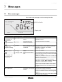
7.1
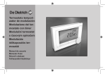
Error messages
This is what a fault message or service message looks like:
No connection
to outside
sensor
Fault indication
Display text
Menu
Program
T000063-04-A
Error codes
Fault indication
Display text
Solution
F200
No connection to
outside sensor
F203
Faulty connection to
boiler
F214
Incorrect room
temperature reading
c and Z are lit
up.
No connection to outside
sensor.
Check the boiler's connection to the outside
temperature sensor.
c is lit up.
Communication error.
Check the connection.
Check the connection to the boiler.
c is lit up.
Room temperature is out of Room temperature measurement is incorrect.The
measuring range or sensor temperature sensor may be defective if the room
is defective.
temperature is between -5℃ and 65℃.
Contact your installer.
F215
Controller failure
F216
F219
No connection with
base station (Only
controller RF).
c is lit up.
Internal fault. Controller
failure.
Contact your installer.
w and c are lit
up.
Wireless communication
fault.
Check whether the base station for the boiler is on
and is functioning correctly (Consult the transmitter
manual if necessary).
If there is no connection between the controller and
the base station, restore it as follows: Put the base
station in connection mode.
(Consult the transmitter manual if necessary).
Select in the controller: Menu > Settings > Users >
Connection > Base station > Connect.
If this does not solve the problem, look for another
location for the controller and/or the base station.
Or remove obstacles that could interfere with the
RF signal.
F227
Wait for RF sensor
Wait for RF sensor
Wait for RF sensor
information. This may take
15 mins.
This fault code can appear after controller RF starts
again (eg after changing the batteries).
As soon as controller RF has received a message
from the connected RF sensors, the message will
disappear.
If the RF sensors fail to report, another fault code will
be displayed after 15 minutes.
030211 - 120666-AG
30
7. Messages
Error codes
iSense
Fault indication
Display text
Solution
The water pressure Current water
is too low
pressure
e and c are lit
up.
E-Code: Boiler
E-Code
failure
c is lit up.
The water pressure in your Top up the water in the central heating system. See
central heating system is
the installation and service manual for the boiler.
too low.
Boiler failure: See the
installation and service
manual for the boiler.
Or equipment between the
controller and boiler.
Use the E code to find the fault in the equipment to
be controlled (For example, boiler, cascade
controller or c-Mix).
Controller batteries c and v are lit up
flat
-
The batteries are almost empty. Replace the three
AA batteries.
7.2
Maintenance message
Boiler service required
Fault indication ? is lit up.
Display text
Maintenance service type (A,B, or C) required in two months. Make an appointment for this with your
installer. Telephone number:
Solution
Contact your installer to have the central heating boiler serviced.
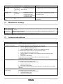
7.3
Incidents and solutions
Problem
Solution
The central heating comes on
too early in the morning.
Adjust the Max pre-heating time setting.
The home may well not be up to temperature on time as a result.
The home is not warm on time. 4
Open the radiator valve further when the radiators warm up.
4
Adjust the Max pre-heating time setting.
4
Increase the Max. pre-heat. By adjusting this to Fastest for example
For weather-compensated control you have the following options:
4
Set the radiator thermostat valves correctly.
4
4
Adjust the heating curve (Refer to the installation instruction booklet for further
information).
Change the control strategy.
There may also be technical problems with the central heating installation.
In that case contact your installer.
The house is too warm.
Weather-compensated control means that no account is taken of the room temperature. Solve
the problem in one of the following ways:
4
Set the radiator thermostat valves correctly.
4
Adjust the heating curve.
4
Change the control strategy.
With room control, the heat-up rate may be too high or the controller may not be correctly
calibrated.
The house does not become
warm enough.
31
Weather-compensated control means that no account is taken of the room temperature. Solve
the problem in one of the following ways:
4
Set the radiator thermostat valves correctly.
4
Increase the heating curve.
4
Change the control strategy.
030211 - 120666-AG
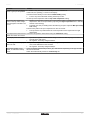
iSense
Problem
7. Messages
Solution
It takes a long time for the tap 4
Boiler: It may be that the DHW standby function is switched off.
water to get up to temperature. In that case, the symbol T is shown in the display.
Control the DHW standby function with the DHW standby setting
4
Tank: It may be that the boiler is being heated up too late.
Set the tap water temperature with the Tap water temperature setting.
The boiler starts heating the
4
home or the tap water at night,
even though the controller is set
to low.
4
Weather-compensated control (OTC) means that the boiler is controlled by the outside
temperature. This can be prevented by adjusting the Night temperature limit or selecting
another control strategy
The boiler can start pre-heating before the following set point. Adjust the Max pre-heating
time setting.
The home may well not be up to temperature on time as a result.
4
The tap water is only heated when the room temperature set is higher than the night
temperature
The temperature measurement Correct the temperature measurement using the Calibration setting.
differs from what I am used to.
The display does not function. 4
The backlight for the display
does not work.
The boiler supplies no hot
water, or water that is barely
warm.
030211 - 120666-AG
OpenTherm regulator: Check that the wiring is correct and that the plug for the boiler is
securely in the wall socket.
4
RF regulator: Insert fully charged batteries.
4
OpenTherm regulator: Your boiler may not support the OpenTherm Smart Power. In that
case, insert batteries into the controller.
4
RF regulator: Insert fully charged batteries.
It may be that the DHW standby function T is switched off. Depending on the type of boiler,
this can be the result.
Switch the DHW standby function to Continuously on.
32
8. Menu / Technical data
iSense
8
Menu / Technical data
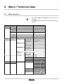
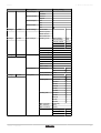
8.1
Menu structure
For user levels Basic and Normal, some menu items are
not visible.
The Set boiler menu depends on the options offered by
the boiler.
Menu options
Program
Factory setting
Clock prog.
Clock prog. A
Clock prog. B
Day temp.
20À
Night temp.
15À
Frost temp.
6À
Holiday prog.
Fireplace
Settings
Users
Display
Key lock
User mode
Info line small
Time
Info line large
Act. room temp
Light time-out
15seconds
Off
☑
On
⃞
On + pin code
⃞
Basic mode
⃞
Normal mode
☑
Extended mode
⃞
Outside sensor
0.0
Inside sensor
0.0
Base station
Connect
Reset
Calibration
Connection
RF outsidesensor Connect
Disconnect
RF room sensor
Connect
Disconnect
Settings
33
Installer
DIGI input
Mode
Not used
☑
Day temp.
⃞
Night temp.
⃞
Service
⃞
Water pressure
⃞
Time open
1 min
Time close
1 min
Contact
Normal. Closed
☑
Normally Open
⃞
030211 - 120666-AG
iSense
8. Menu / Technical data
Menu options
Remote input
Phone number
Service report
Service code
Settings
Installer
Boiler settings
Factory setting
Allow
☑
Disallow
⃞
Service
()
Repair
()
Off
☑
On
⃞
Off
☑
On
⃞
Parameters
Restore param.
Reset service
Start detection
Settings
System
OTC settings
Heating curve
Base outside
20℃
Base flowtemp
20℃
Climate outside
-10℃
Climate flowtemp 90℃
Curvature
Settings
System
Control settings
Temperature
Settings
System
CH system
RT effect
5
Heat limit day
21℃
Heat limit night
10℃
RTC
☑
OTC + RT
⃞
OTC + C-RT
⃞
OTC/RTC ECO
⃞
OTC
⃞
RTC + limit
⃞
Comfort corr.
Off
⃞
On
☑
Frost protection
-10℃
Pump control
Off
⃞
On
☑
Extra Slow
☑ eVita
Slowest
⃞
Slower
⃞
Normal
☑
Faster
⃞
Fastest
⃞
Slowest
⃞
Slower
⃞
Normal
☑
Faster
⃞
Fastest
⃞
Heating rate
Cooling rate
030211 - 120666-AG
Max. pre-heat
(180 min)
Min. CH temp.
(6℃)
Max. CH temp.
(90℃)
Zoning
No zoning
☑
1 & 2 separate
⃞
2 follows 1
⃞
34
8. Menu / Technical data
iSense
Menu options
Settings
DHW
Anti-Legionella
Standby
Factory setting
Activate on...
⃞
Off
☑
Continuous off
⃞
Continuous on
⃞
Night temp off
☑
DHW temperature Temperature
Settings
Time/date
☑ 60℃
Clock prog.
⃞
Europe
☑
Other
⃞
Manual
⃞
Set time
Set date
Summer time
Information
8.2
Technical characteristics
Specifications
Dimensions
96 x 144 x 34 (l x b x h) mm
Height excluding buttons 96 x 144 x 25 (l x b x h) mm
Power supply
OpenTherm regulator
Via OpenTherm or separate 5Vdc adapter
RF regulator
Electrical connection
Via batteries or separate 5Vdc adapter
OpenTherm regulator
OpenTherm communication. Connection for low-voltage wires
RF regulator
Bi-directional secure communication
Batteries
3 x AA Batteries. Service life: Dependent on the make of battery
Digital input
Ambient conditions
Volt free contact (Contactor)
Storage conditions
Temperature: -25℃ - 60℃
Relative humidity 5% - 90% no condensation
Operating conditions
Temperature
Without batteries: 0℃ - 60℃ . With batteries: 0℃ - 55℃
Room temperature
Measurement range: -5℃ - 65℃
Maximum temperature deviation at 20℃ : 0,3 ℃
Outside temp
The measurement is taken in the boiler and passed to the controller. Consult the boiler
documentation regarding the accuracy of the measurement.
Temperature control area
5 - 35℃
Calibration options
Inside and outside temperature sensor: -5 output +5 In steps of 0,5 ℃
Adjustment
Modulating temperature control
The control can be optimised
Room control
Overshoot: Maximum 1℃ after pre-heating
Temperature variation: Less than 0,25℃
Adjustment strategies
Adjustment of the room temperature
Control as a function of the temperature
4 Combination options
Features of the controller
Backlight
Colour: blue
Date/Time indication
Time: 24h Clock. Accuracy: To about 365 seconds per year
35
030211 - 120666-AG
iSense
8. Menu / Technical data
Specifications
Date: Day - Month - Year.
Automatic switching to summer time
Programs
2 clock programs with 6 switch points per day
Boiler clock program with 6 switch points per day
16 Holiday programs
Day, Night, Frost protection, Summer mode, Fireplace mode
Control precision
Temperature: 0,5 ℃
Programme schedule: 10 minutes
Wireless range of controller RF
The range of the controller RF in buildings is generally 30 metres. However, this depends to
a large extent on the situation ¼ "Position of the regulator", page 5
Controls
Controlled from the menu, using push buttons and a push-turn button
Mounting
Directly on the wall using screws. Or built-in junction box as per standards
Built-in system possible using built-in part (art. S100994)
Quality marks and compliance
with standards
EMC: 2004/108/EC - EN50165 (1997), 55014, 55022
Emission: EN61000-6-3
Immunity: EN61000-6-2
Drop test: IEC 68-2-32
RoHS compliant
OpenTherm V3.0 Smartpower (Only controller RF)
ETSI 300-220 (Only controller RF)
Protection classification
030211 - 120666-AG
For wall installation: IP20 For the built-in system: IPx4
36
© Copyright
All technical and technological information contained in these technical instructions,
as well as any drawings and technical descriptions supplied, remain our property
and shall not be multiplied without our prior consent in writing.
030211
120666