1
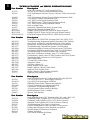
TABLE OF CONTENTS
GENERAL INFORMATION .................................................... SECTION 1
Model Plate, Parts Stock, Training Books, Bolt Torques,
Lubrication, Spark Plug, RPM Settings
TRACTOR BRAKE ADJUSTMENTS ...................................... SECTION 2
Lawn, Yard, And Garden Tractors
TRANSAXLES AND HYDRO INFORMATION .................. SECTION 3
Hydro Oil/Filter Change, Hydro Troubleshooting Charts
MOWER DECKS, BLADES, BAGGER INFORMATION .... SECTION 4
Deck Leveling, Deck Belts Replacing, Deck Safety Guards,
Deck Repairing And Service Tips, Blade Listing
BELT INFORMATION.............................................................. SECTION 5
ELECTRICAL AND BATTERIES ............................................ SECTION 6
Battery Testing And Charging, Troubleshooting Starter Circuits,
Electric Clutch Adjusting, Operator Presents System
TRACTOR FRAME AND STEERING .................................... SECTION 7
Tractor Frame And Steering Repairs
1
2
3
4
5
6
7
ENGINE INFORMATION ....................................................... SECTION 8
8
CRT TILLERS ............................................................................. SECTION 9
9
SPECIALTY TOOLS AND TEST EQUIPMENT .................... SECTION 10
10
Part No. 163578 - REV 4
NOTES
4
FRIGIDAIRE HOME PRODUCTS
1
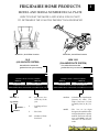
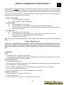
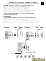
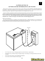
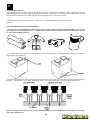
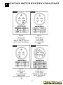
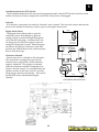
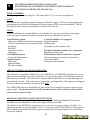
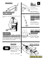
MODEL AND SERIAL NUMBER DECAL PLATE
HOW TO READ THE MODEL AND SERIAL DECAL PLATE
TO DETERMINE THE YEAR THE PRODUCT WAS PRODUCED
Model No., Serial Plate Location
Model No., Serial Plate Location
OLD
(JULIAN DATE SYSTEM)
NEW 1993
(CALANDER DATE SYSTEM)
One white bar means the
product has one year warranty
Two white bars means the
product has two year warranty
{
{
CONFORMS TO ANSI B71.1-1990 SAFETY STANDARDS
MODEL NO.
CONFORMS TO ANSI B71.1-1990 SAFETY STANDARDS
SERIAL NO.
3155S 001227
917.255970
MODEL NO.
SERIAL NO.
917.255970
012793A 001765
FOR SERVICE AND PARTS ALWAYS GIVE THE MODEL NO.
FOR SERVICE AND PARTS ALWAYS GIVE THE MODEL NO.
SEARS, ROEBUCK AND CO., Hoffman Estates, IL 60179 Made in U.S.A. 138037
SEARS, ROEBUCK AND CO., Hoffman Estates, IL 60179 Made in U.S.A. 138038
MODEL #
315
- Represents the
315th day of the
year.
5
- Last Digit of Year
1985
S
- Plat Code
{
{
917.255970
012793A - Calendar date of production
(January 27, 1993). The
Alpha character is Final
Assembly Line (A, B, C, D,
etc.
MODEL #
001765
SOURCE
1227 - Number of Units
Produced
5
- The last six (6) digits
designate the number of the
units produced for a specific
model #. Each new unit will
start with 001001 and will
continue in consecutive
order.
1
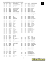
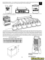
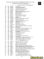
RECOMMENDED PARTS STOCK TRACTOR & TILLER
DIV. PLS.
PART #
DESCRIPTION
DIV.
O71 917
25034
44" STD Lift Blade
O71
PLS.
917
PART #
148698
DESCRIPTION
Terminal Ring
O71
O71
917
917
25036
25321
38" STD Lift Blade
42" STD Lift Blade
O71
O71
917
917
148763
150280
Primary Deck Belt
Clutch Bolt Kit
O71
O71
O71
917
917
917
25741
59904
65139
38" STD Lift Blade
Tube 5.3 / 4.5 X 6
Valve Stem
O71
O71
O71
917
917
917
151785
152443
153535
Cam Roller Kit
46" Prem Mulch Blade
Pulley
O71
O71
917
917
71208
127218
Bushing
Link Front
O71
O71
917
917
154963
155106
PTO Switch
Bushing Kit
O71
O71
O71
917
917
917
128774
129895
129963
Man Housing 38/42
Bearing
Washer
O71
O71
O71
917
917
917
155132
156109
157353
Hood Repair Kit
Belt Keeper Kit
46" Blade Hi Lift
O71
O71
917
917
130171
130652
Trunion
O71
44" Prem Hi Lift Blade O71
917
917
157722
158818
Screw
Primary Deck Belt
O71
O71
O71
917
917
917
130759
130794
130968
Latch
Mandrel
Deflector 42"
O71
O71
O71
917
917
917
158913
Ignition Switch
160793
Bagger Latch
12000029 E-Ring
O71
O71
917
917
130969
131006
Primary Deck Belt
Ground Drive Belt
O71
O71
917
917
12000039 E-Ring
17490612 Screw
O71
O71
O71
917
917
917
131264
131290
131340
Primary Deck Belt
Primary Deck Belt
Bolt shoulder
O71
O71
O71
917
917
917
17580520 Bolt
71161010 Screw
532124029 Lens
O71
O71
917
917
131494
131845
Flat Idler
Brake Pad
O71
O71
917
917
532126938 Bumper
532132800 Knob
O71
O71
O71
917
917
917
132673
133957
134148
Pin Clevis / Shear Pin O71
Gauge Wheel
O71
38" Mulch Blade
O71
917
917
917
101342N
102403X
104239X
Belt
Flat Idler
Bearing
O71
O71
917
917
134149
134998
42" Mulch Blade
O71
38" Prem Mulch Blade O71
917
917
104418X
104445X
38"Cross Blade
Switch
O71
O71
O71
917
917
917
136321
136420
136819
Runner RH
Mulch Cover
Mandrel
O71
O71
O71
917
917
917
1044R
104757X
105709X
Washer
Hub Cap
Spring
O71
O71
917
917
136874
136888
Sector
Baffle
O71
O71
917
917
106085X
106412X
Ground Drive Belt
Belt
O71
O71
O71
917
917
917
137153
137380
137553
Ground Drive Belt
O71
50" Prem Hi Lift Blade O71
Shaft 44/46/50
O71
917
917
917
106578X
106729X
106888X
Brake Mandrel
Ground Drive
Brake Spring
O71
O71
917
917
137644
137646
Bolt shoulder
Shaft Mandrel 38/42
O71
O71
917
917
106909X
106932X
Screw
Knob
O71
O71
O71
917
917
917
138255
138497
138498
Primary Deck Belt
38" Hi Lift Blade
42" Hi Lift Blade
O71
O71
O71
917
917
917
106933X
108597X
108824X
Knob
Belt
Fuse
O71
O71
917
917
138971
139774
42" Prem Hi Lift Blade O71
38" Prem Mulch Blade O71
917
917
109310X
109553X
Key Ignition
Switch
6
RECOMMENDED PARTS STOCK TRACTOR & TILLER
DIV. PLS.
PART #
DESCRIPTION
DIV.
O71 917
139775
42" Prem Mulch Blade O71
PLS.
917
PART #
109808X
DESCRIPTION
Hood Latch
O71
O71
917
917
139868
140080
Arm Support
Bolt
O71
O71
917
917
109816X
110452X
Nyliner T
Push Nut
O71
O71
O71
917
917
917
140218
140301
140403
Ground Drive Belt
Ignition Switch
Key Ignition
O71
O71
O71
917
917
917
110485X
110883X
110884X
Bearing
Belt
Belt
O71
O71
917
917
144200
144959
Primary Deck Belt
Primary Deck Belt
O71
O71
917
917
120951X
120961X
Brake Puck
Brake Puck
O71
O71
O71
917
917
917
145960
145967
145956
Primary Deck Belt
Belt
Belt
O71
O71
O71
917
917
917
121263X
121687X
121748X
38" High Lift
Mandrel
Washer
O71
O71
917
917
146077
146154
Bumper
Solenoid Kit
O71
O71
917
917
121749X
121798X
Washer
50" STD Lift
O71
O71
O71
917
917
917
146525
146682
123796X
Wing nut
Spring
Belt
O71
O71
O71
917
917
502
123549X
123713X
91954
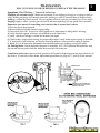
Fuel Cap
Spring
Bulb
O71
O71
917
917
124035X
124035X
Support
Shaft
O71
O71
502
502
424285
456246
Solenoid
30" Blade
O71
O71
O71
917
917
917
125907X
126847X
126875X
Belt
Bushing
Rivet
O71
O71
O71
502
502
502
492574
Housing
54390E701 Blade
91742E701 Blade
O71
O71
917
917
2029J
3366R
Weld Nut
Bearing
O71
O71
502
502
91871E701 Blade 40"
92117E701 Blade
O71
O71
917
917
4921H
4921H
Clip Retainer
Retainer Ring
O71
O71
536
536
330278
339093
Blade
Belt
O71
O71
O71
917
917
917
6266H
6554J
6555J
Washer
Tine CRT
Tine CRT
Spark
Plugs
O71
O71
917
917
6941R
7152J
Belt
Tube 18X 9.5— 8
O98
O98
661
661
H10C
J17LM
H10C/216
J17LM/245
O71
O71
O71
917
917
917
7631J
7662J
8134H
Runner
O98
Bulb
O98
Tube 16 X 6.5 / 7.5 —8 O98
661
661
661
PM-4
RC12YC
RJ12C
J19LM/458
PLUG
RJ12C/308
O71
O71
917
917
9040H
9180R
Bearing Wheel
Belt
O98
O98
661
661
RJ12YC
RL86C
RJ12YC/85
L86C/RL86C
O71
O71
O71
O71
O71
O71
24101
24102
24103
Belt
Belt
Belt
O98
O98
O98
661
661
661
DP26
N4C
RJ19LM
RV154C
PLUG
PLUG
O71
O71
O71
O71
24655
24694
Blade Prem
Belt
O98
661
RV17YC
PLUG
O71
O71
O71
O71
O71
143
33500
96145
34279B
Fuel Stabil
Battery
Filter
O98
O98
980
980
Standard Parts
STD365402Switch
STD624010Hitch Pin
O71
O71
143
143
35403
35404
Air Cleaner
Filter
O98
980
STD560907PIN 8 PK
7
1
1
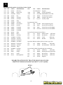
RECOMMENDED PARTS STOCK TRACTOR & TILLER
DIV. PLS.
PART #
DESCRIPTION
DIV.
PLS.
PART #
DESCRIPTION
O71
O71
143
143
632633
799021
Inlet Assy
Brake Pads
*O92
Recommended
192
730301
O71
O71
O71
247
500
500
736-0242
222698
270843
Washer
Key
Air Filter
*O92
O92
O92
192
192
192
25-357-06 10W30 Kohler Oil 32 OZ.
144335
Tire Sealant 5 Gal Pail
100035
Pump for Tire Sealant
O71
O71
500
500
271962
272403
Air Filter
Filter
*O92
Or
buy oil
O71
O71
O71
500
500
500
272490
280104
291675
Air Filter
Gear Starter
Seal Oil
Recommended Tools
O92
150
DS-100
O92
150
19435
O71
O71
500
500
394018
394019
Cartridge
Cartridge
O92
O92
O71
O71
O71
500
500
500
399806
491588
495878
Cartridge
Filter
Drive
Service Kit for Current Service Flashes
O71
917
158739
Debris Guard
O71
O71
500
501
496894
12-050-01
Air Filter
Oil Filter
O71
O71
917
917
159258
139573
Washer Kit
V Belt
O71
O71
O71
501
501
501
12-083-05
12-083-08
25-050-02
Air Filter
Precleaner
Fuel Filter
O71
917
159717
Belt Kit
Special 46" Blades for Bahia, Field or Pasture type Grass
O71
O71
501
501
45-083-01
45-083-02
Precleaner
Air Filter
O71
O71
O71
O71
O71
501
501
502
47-083-03
52-050-02
54211
Filter
Oil Filter
Adapter
Service Kits For High Volume Rough Service Markets
O71
917
137797
Frame Kit
(SF71-243)
O71
O71
502
502
55547
91178
Flange
Pulley
O71
O71
917
917
140342
149681
Bushing Kit 96 Update Book
Kit Steering
(SF71-297)
O71
502
91334
Bearing Wheel
O71
071
917
917
149684
151786
Kit Steering
Ring Kit
150
150
917
917
Supplies
48 OZ. SAE 30 OIL
Locally in bulk
Deck Straightening tool
Starter Drive install tool
19436
Starter Drive tool for Briggs
25-761-18 Starter Drive tool for Kholer
157033
159705
163996
8
(SF71-365)
(SF71-366)
(SF71-378)
46" Blade
(SF71-390)
46" Bahia Blade (SF71-390)
SEARS STEALTH HOOD TRACTOR MANUALS IN 1998
OMITTED THE HEADLIGHT SOCKET 71/917/163996
4152J
(SF71-364)
(SF71-297)
1
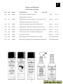
Cleaners and Lubricants
Sold in Case Lots Only
DIV.
PLS
PART #
DESCRIPTION
SIZE
O92
192
81010C
Multi-Purpose Cleaners & Degreaser
CASE SIZE
14oz can
12 cans
15oz can
12 cans
Biodegradable Citrus Force
O92
192
84010C
Multi-Purpose Penetrant, Lubricant, Corrosion Preventive
& Moisture Displacer Fourway Force Case
O92
192
85010C
Multi-Purpose White Lithium Grease Lithium Force
14oz can
12 cans
O92
192
87010C
‘Multi-Purpose Carburetor & Choke Cleaner Carb Force
15oz can
12 cans
O92
192
88010C
‘Multi-Purpose Battery Spray Protection Battery Protection
14oz can
12 cans
O92
192
89010C
Contact Cleaners (Elec. Components) Refrigeration
14oz can
12 cans
O92
192
81410C
Dry Teflon, Lubricant
10oz can
12 can
O92
192
82010C
Multi-Purpose Cleaner and Degreaser Clean Force
32oz bottle12 bottles
O92
192
86010C
Multi-Purpose Hand Cleaner and Skin Softener Hand Force
16oz bottle12 bottles
9
1
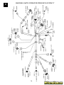
TECHNICAL TRAINING and SERVICE INFORMATION BOOKS
Part Number
Description
from F.H.P. Source 917 order from D92/192
163578
Tractor & CRT Tiller Service Information Book
169291
1999 Craftsman & Wizzard Tractor, Mowers, Tiller Accessories
Book
169418
1999 Craftsman & Wizard Tractor Wiring Schematics Book
168830
1999 Service Update Information Book
158222
1997 FHP Tractor Quick Reference Book
158223
1997 FHP Mowers / Tillers Quick Reference Book
158224
1997 FHP Tractor Wiring Schematics Book
168695
Deck Leveling Video
169287
Automatic Transmission/Drive System Video
139132
Electrical & Charging Systems Book
BLN-50432
HYDRO GEAR LT Hydro IHT Service & Repair Manual
BLN-50334
HYDRO GEAR GT Hydro 3010L Service & Repair Manual
99924-2041-01
KAWASAKI Engine Model FD590V 18HP Service Manual
Part Number
MS-8518
MS-8798
MS-9152
MS-9557
MS-9884
MS-2285
MS-2857
MS-0279
MS-0575
MS-0981
MS-0709
MS-0710
MS-2288
MS-3957
MS-3992
MS-5437
MS-5441
270962
271172
Part Number
692509
691462A
691218
695244A
695907
695590
695933
694862
Part Number
TP-2339
TP-2450
TP-2289
TP-2131
ES-103
ES-2007
TP-2372
ENS-967
TP-2067
Description
from BRIGGS & STRATTON Training & Ref. Mtl. (D92/192)
Troubleshooting Magnetron Ignition Systems (1985 Update)
Quick Check, an Effective Troubleshooting Tool (1986 Update)
Systematically Troubleshooting Ignition, Carbureton and Compression
Troubleshooting Carburetion Systems (1988 Update)
Troubleshooting Ignition, Starting, and Charging Systems (1991Update)
Carburetor Problem Solving Chart, page 10 (1991Update)
Troubleshooting Governor Systems (1993 Update)
Float Style Carburetor Leakage, page 27 (1994 Update)
Troubleshooting - Ignition Tester, DC Shunt, Leakdown Tester (1995 Update)
Troubleshooting Carburetors (1996 Update)
OHV Gasket Chart
V-Twin OHV Gasket Chart
Alternator Chart
Air Filter Charts (2)
Handy Repair Check Chart
Single Cylinder L-Head Gasket Chart
Opposed Twin Gasket Chart
Single Cylinder L-Head Engine MANUAL
Opposed Twin Engine MANUAL
Description
from TECUMSEH Source 143 Training & Ref. Mtl. order D92/192
3 to 10 HP 4 Cycle "L" Head Engine MANUAL
8 to 18 HP Cast iron Engine MANUAL
PEERLESS PowerTrain Components MANUAL
4 Cycle Overhead Valve Engines MANUAL
Carburetor Troubleshooting Booklet
4 Cycle Engine Failure Analysis Booklet
Quick Reference Chart / Booklet
Special Tools Booklet
Description
from KOHLER Source 501 Training & Ref. Mti. order D92/192
Command Single Cylinder CV11-CV16 Service Manual
Command Twin Cylinder CV18-CV25 Service Manual
Magnum Twin Cylinder MV18-MV20 Service Manual
Troubleshooting Flow Chart & Guidebook
General Maintenance Video An Ounce of Prevention
Product Specifications; Sales Brochure on Models
Specifications & Tollerances Wallchart
Gaskets Wallchart
Air Cleaner Elements Wallchart
10
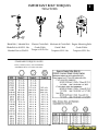
IMPORTANT BOLT TORQUES
TRACTORS:
1
Blade Bolt / Mandrel Nut
Electric Clutch Bolt
Blade Bolt to 30-35 Ft. Lbs.
Grade 5 Bolt
Grade 5 Bolt
Grade 5 Bolts
Mandrel Nut to 55-65 Ft.
Torque to 50 Ft. Lbs.
Torque to 35 Ft. Lbs.
Torque to 35 Ft. Lbs.
Mechanical Clutch Bolt Engine Mounting Bolts
STANDARD TORQUE VALUES
BOLTS, SCREWS, NUTS, AND FASTENERS
ASSEMBLED INTO CAST IRON OR STEEL.
11
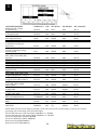
1
TECUMSEH ENGINES
3HP thru 6.2HP, L Head
and HTL Rotary
5HP thru 6.6HP Hi Torque
w/Extruded Carb.
4HP, 5HP, OHV Rotary 6HP
OHV Slant Horizontal
8HP, 10HP Vertical L Head
12HP, 12.5HP Vertical
w/Stationary Cooling Air
Inlet Screen
12HP, 12.5HP, 16.5HP OHV
Vertical w/Rotating Cooling
Air Inlet Screen
BRIGGS AND STRATTON
3HP, 3.5HP, Classic 4HP, 5HP,
Quantum
5HP Horizontal L Head
8HP Horizontal L Head
12HP, 12.5HP, 13HP Singles Cyl.
15HP, 15.5HP OHV
14HP, 16HP, 18HP, 19HP,
Opposed Twins
20HP Opposed Twin w/Filter
13HP, 14HP, 15HP, 16HP, 17HP
Vanguard Single OHV + Intek/V
14HP, 16HP, 18HP, 20HP, 22HP
Vanguard Twin OHV+ Intek/V
KOHLER ENGINES
CV 12.5HP, 14HP, 14.5HP,
15HP, 15.5HP
CV 20.5HP, 22HP
22.5HP, 25HP
M18HP, 20HP, MV18HP,
18.5HP, 19HP, 20HP
HONDA ENGINE
5HP GXV140 NGK Brand
ONAN ENGINES
20HP
KAWASAKI
18HP NGK
OEM PLUG#
GAP
STD PLUG#
OIL GRADE
OIL CAPACITY
RJ19LM
.030
PM4
30W
20.OZ
RJ19LM
.030
PM4
30W
27.OZ
RN4C
RJ17LM
.030
.030
NONE
NONE
30W
30W
20.OZ
32.OZ
RL86C
.030
NONE
30W
32.OZ
NC4
.030
NONE
30W
32.OZ
RJ19LM
RJ19LM
RJ19LM
RJ19LM
RC12YC
.030
.030
.030
.030
.030
PM4
PM4
PM4
PM4
NONE
30W
30W
30W
30W
30W
20.OZ
20.OZ
44.OZ
48.OZ
48.OZ
RJ19LM
RJ19LM
.030
.030
PM4
PM4
30W
30W
48.OZ
56.OZ
RC12YC
.030
NONE
30W
56.OZ
RC12YC
.030
NONE
30W
56.OZ
RC12YC
.040
NONE
10W30
64.OZ
RC12YC
.030
NONE
10W30
64.OZ
RV17YC
.035
NONE
30W
56.OZ
NGKBPR5ES
.030
NONE
30W
20.OZ
RS14YC
.025
NONE
30W
56.OZ
BPMRGA
.025
CJ8
10W30
70.OZ
NOTE: Make sure the correct engine spark plug is used with (correct reach and heat range), as the use of a incorrect
spark plug will cause damage to the customer engine.
Tractor 1992 and newer with vented decks 3350 RPM + or - 50 RPM
Tractor 1991 and older with standard decks 3550 RPM + or - 50 RPM
Tractor low RPM single cylinder 1800 RPM
Tractor low RPM twin cylinder 1400 RPM
Rotary mower high RPM 3200 fast
Rotary mower low RPM 2600 slow
12
MAINTENANCE (M/A) CHECK
1
Tractor / Riding Mowers
• Tune engine, Check: rpm engine speed ,charging system , ignition, spark plug, throttle & choke
controls, clean engine cooling fins, replace air filter, change oil, oil filter, and fuel filter.
• Check & adjust tires for proper inflation.
• Lubricate moving parts, steering, linkage, and grease all fittings.
• Test overall operation of equipment and ensure that all safety features are operating properly.
• Check electrical system and clean battery terminals.
• Sharpen or replace cutting blades.
• Check blade mounting bolt Torque with Torque wrench ( 30 to 35 ft lbs).
• Check and adjust brakes & do brake test. See brake adjustment section for brake test.
• Compliance check operator present system and blade brake system, blades stop within 5 seconds
when disengaged.
• Check belts & pulleys.
• Adjust guage wheels, (off of ground).
• Check deck rake and level.
Tillers
• Remove fuel from tank & bowl.
• Tune engine , Check: rpm engine speed, Ignition, carburetor, clean or replace air filter and change
oil.
• Lubricate moving parts, pivot point and cable.
• Inspect, adjust or replace as needed all belts and chains as applicable.
• Test overall operation of equipment and ensure that all safety features are fully operational.
Snow Throwers
• Tune engine , Check: rpm engine speed , Ignition system, carburetor, battery, replace spark plug
and change oil winter weight only.
• Lubricate moving parts: pivot point, cables, auger shaft, grease zerk, and chains.
• Inspect, adjust or replace (as needed) all drive belts, belt guides.
• Check manual starter and electric starter if so equipped.
• Check and adjust disk drive assembly and auger cable.
• Check chute control rod and deflector.
• Test overall operation of the snow thrower.
• Check for proper operation of all safety features.
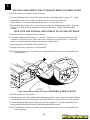
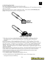
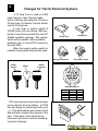
POKE HOLE IN TOP
OF FILTER HERE.
PREVENT OIL FROM SPILLING ALL OVER THE
WHEN CHANGING FILTER. POKING A HOLE
IN THE TOP OF THE FILTER WILL VENT SYSTEM
AND ALLOW OIL TO DRAIN OUT THROUGH
ENGINE SUMP.
13
1
TRACTOR LUBRICATION
Important: do not oil or grease the pivot points which have special nylon bearings. Viscous
lubricants will attract dust and dirt that will shorten the life of the self-lubricating bearings. If you
feel they must be lubricated, use only a dry, powdered graphite type lubricant sparingly.
NOTE: HYDRO TRANSAXLE FLUID
Typically, a 20W-50 engine oil with an API
classification of SH/CD is recommended for
most normal operating conditions. In some
cases, such as northern climates where
temperatures commonly drop below 20°F it
may be necessary to perform seasonal oil and
filter changes to achieve the proper
performance levels expected from a hydrostatic
transmission. The recommended “winter” fluid
would then become a 10W-40 engine oil. An
alternative to seasonal fluid and filter changes
would be to use a synthetice engine oil such as
15W-50 Mobil 1. This choice offers not only
better cold weather performance, but also
improves high temperature protection over
both of the previously mentioned fluids. The
volume of fluid required to refill a transaxle is
approximately 2-1/2 quarts.
1. SAE 10W30 Motor Oil API-SG
2. General purpose grease
3. Refer to customer responsibilities "Engine"
section in owners manual.
4. Grease shell dorina type 0 20 oz.
5. SAE 20W50 Motor Oil API SG/CD
Lawn Tractor:
310-500, 310-650, 310-750 IHT Hydro
transmission holds approximately 80 oz.
20W50 motor oil.
Garden Tractor:
210-3010L GT Hydro transmission holds
approximately 60 oz. 20W50 motor oil or
10W40 or 15W50 Mobil 1 synthetic motor oil.
1. SAE 30 or 10W30 Motor oil API - SG
2. General purpose grease
3. Refer to customer responsibilities “Engine”
section in owner’s manual
4. Dana transaxle 16 oz. Shell dorina type 0
grease. Part number 120416X
Peerless transaxle: 30 oz. Bentonite grease.
N O T E : on transaxle with grease, only change or
add grease when making repairs to the inside of
transaxle.
1. SAE 30 Motor Oil API-SF/SG holds 128 oz.
2. General purpose grease.
3. Refer to customer responsibilities "Engine"
section.
4. Spray silicone lubricant (move boots to
lubricate)
14
I M P O R T A N T : do not oil or grease the Pivot
points which have special nylon bearings.
Viscous lubricants will attract dust and dirt that
will shorten the life of the self-lubricating
bearings. If you feel they must be lubricated
use only a dry, powdered graphite type
lubricant sparingly.
SERVICE ORDER DOCUMENTATION
1
It’s important to always document the reason for failure on the service order. On an in-warranty
product, do not close the service orders as in-warranty, if the failure is due to customer abuse, neglect
or even accident. Verify and document as much information as possible about a service call on the
service order. Especially when a major component has been replaced, here are a few examples of
acceptable and not acceptable service orders.
1 - NOT ACCEPTABLE
A.
Service Requested: Won’t Run
B.
Tech Comments: Replaced Engine
2 - ACCEPTABLE
A.
Service Requested: Won’t Run
B.
Tech Comments: Found black, dirty oil in pump, connecting rod broken.
Customer abuse, changed engine, tested for safety compliance and charged customer.
C.
Call closed as collect
3 - ACCEPTABLE
A.
Service Requested: Won’t Run
B.
Tech Comments: Found engine locked. Oil normal, no external causes found.
Internal component failed. Replaced engine and tested.
C.
Call closed as in-warranty
Note: The cost of an engine replacement must be supported by what you have determined caused the
failure.
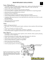
Engine Replacement
Other than catastrophic internal engine failures, ordering a replacement engine is not
always the solution. Many perfectly good engines have been received and inspected
at the Dallas Rebuilding facility. Before replacing an engine check the following items
first:
Complaint:
Noisy
• Disconnect belt(s), run engine with no load.
• If an engine is noisy, determine where noise is coming from. If engine runs normally but has a knock,
pull head(s) and check for carbon buildup.
High Oil Consumption
•
•
•
•
•
•
Is it leaking or burning oil?
Check integrity of all seals and gaskets (as described in the Troubleshooting section of this manual).
Ensure breather is operating properly.
Check condition of spark plug. An oil-fouled plug will indicate engine is burning oil.
Check oil type, quality and quantity.
Does the engine smoke? If so, is the smoke black, white or blue?
Won't Run / Locked Up
• Disconnect belt(s), run engine with no load.
• Check external causes.
• Check starter drive to ensure it is not jammed in the flywheel.
15
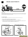
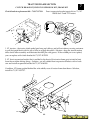
BRAKE ADJUSTMENTS
2
6 FEET
BRAKE TEST
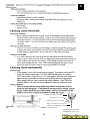
A brake test should be performed whenever Service work is performed on a tractor. Tractor traveling at high speed in highest
gear must stop within 6 feet when the brakes are applied. If tractor requires more than 6 feet to stop, a brake adjustment
should be made before returning tractor to the customer.
TO ADJUST BRAKE
Your tractor is equipped with an adjustable brake system which is mounted on the side of the transaxle.
• Depress clutch/brake pedal and engage parking brake.
• Measure distance between brake operating arm and nut “A” on brake rod.
• If distance is other than dimension shown for your type tractor, loosen jam nut and turn nut “A”
until correct distance is reached. Retighten jam nut against nut “A”.
VGT HYDRO TRANSAXLE
AYP DISC BRAKE TRANSAXLE
WITH PARKING BRAKE “ENGAGED”
1-1/2"
WITH PARKING BRAKE “ENGAGED”
NUT
“A”
JAM
NUT
1-3/4"
NUT
“A”
OPERATING
ARM
OPERATING
ARM
16
JAM NUT
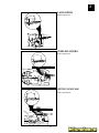
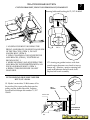
2
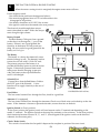
LAWN RIDER
Brake adjustments
1-1/2"
PEERLESS HYDRO
Brake adjustments
1-1/2"
HYDRO GEAR 3000
Brake adjustments
1-1/2"
17
2
BRAKE ADJUSTMENT
STEP-THRU LT/YT HYDROGEAR
0500/0650
STEP-THRU LT/YT GEAR DRIVE
TRANSAXLES PEERLESS + DANA
1-1/2"
SHOWN WITH
PARKING BRAKE
"ENGAGED"
1-9/16"
NUT "A"
SHOWN WITH
PARKING BRAKE
"ENGAGED"
NUT "A"
JAM NUT
OPERATING
ARM
JAM NUT
OPERATING
ARM
GT BRAKE BAUD BRAKE ADJUSTMENT
IMPORTANT: DO NOT OVER TIGHTEN BRAKE. WHEN DEPRESSING CLUTCH BRAKE PEDAL, THE MOTION DRIVE
BELT MUST STOP MOVING (DECLUTCH FROM ENGINE PULLEY) BEFORE BRAKE ENGAGES. IMPROPER
ADJUSTMENT WILL CAUSE HARD SHIFTING AND EXCESSIVE WEAR TO BRAKE LINING.
• Park and turn off the tractor on a level surface.
Place gear shift lever in neutral (N) position.
Disengage parking brake and be sure tractor
does not roll in either direction.
• Lower mower deck (if installed on tractor).
• Snap out access hole cover on left side of tractor
above footrest.
• Loosen jam nut at clevis which will allow brake
rod to be rotated.
• With pliers, from underside of frame, unscrew
brake rod from clevis four (4) to six (6) full turns.
• Start tractor with gear shift lever in neutral (N)
position.
• Slowly depress clutch/brake pedal to the point
where the motion drive belt stops moving. Hold
clutch/brake pedal in this position and engage
parking brake. If belt begins to move after engaging parking brake, reset parking brake by
depressing clutch/brake pedal slightly to next
notch on parking brake.
• Stop engine. Screw brake rod back into clevis
until clevis pin is against rear edge of slot in
brake arm. Do not over tighten (see “IMPORTANT” above).
18
• Tighten jam nut against clevis.
• Replace access hole cover.
• Road test tractor for proper stopping distance
and declutching as stated above. Readjust if
necessary. If proper adjustment cannot be
attained, replace brake band.
GT BAND BRAKE TRANSAXLE
JAM NUT
CLEVIS
PIN
BRAKE
ARM
CLEVIS
BRAKE
ROD
TRANSAXLES
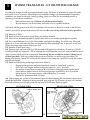
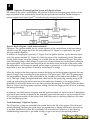
WHAT YOU SHOULD CHECK BEFORE YOU REPLACE THE TRANSAXLE
3
Symptom: Hard Shifting / Transaxle locked up.
Eliminate all customer issues: Make sure customer is not shifting on the go or is trying to shift on
a hill. Shifting on the go will damage transaxle, shifting on a hill is incorrect due to the gear load.
Jerking is caused by clutch misuse. Do not replace transaxle, instruct customer how to use clutch.
Surging happens when a tractor goes down hill and momentarily picks up speed (this is normal).
Remember you cannot fix something on a transaxle that is normal (not broken).
1. Place tractor on level ground.
2. Remove drive belt from transaxle input pulley.
3. If transaxle shifts OK. Tractor has a belt guide out of adjustment or belt guide is missing.
4. Verify that both square axle keys are installed in each wheel hub.
5. Verify shift lever linkage is secure (all fasteners are tight).
6. Check brakes/clutch dwell setting for proper adjustment (verify brake return spring is installed).
7. If transaxle is still locked up you have a internal problem in the transaxle, repair or replace.
8. Note: 30% of all transaxles returned to the rebuild center have nothing wrong with them.
Set Parking Brake: Check the brake clearance it should be. 019"/.024" between the brake disc and
the outside friction puck while the brake lever contacts the brake jaw.
Compliance brake test: tractor on level ground at full speed in highest gear must stop within six (6)
feet or less. If unit fails, follow brake adjustment procedures on page 16, 17 and 18 of this manual.
BRAKE DISC
OUTSIDE FRICTION PACK
.019 BRAKE PUCK CLEARANCE
.024 WITH LEVER CONTACTING
BRAKE JAW BOSS
19
3
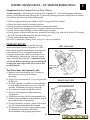
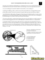
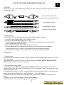
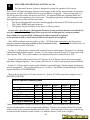
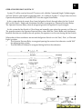
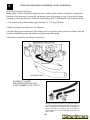
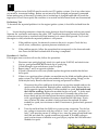
HYDRO TRANSAXLES - GT OIL/FILTER CHANGE
Oil and filter change should occur approximately every 200 hours of operation or when oil condition results in loss of power. More frequent oil and filter changes are recommended if operation
conditions are severe or adverse, such as pulling a plow or a tiller for an extended period, or
operating in very dusty conditions.
•
Run tractor to heat up oil (Warm oil will drain more freely).
•
Be sure tractor is on level surface and catch oil in a suitable container.
Lift tractor off the ground with lift at the drawbar of the tractor or block up tractor so the left rear
wheel is just off the ground and remove left rear tire (Be sure to keep tractor as level as possible).
(#1) Remove oil filter.
(#2) Remove hose from end of swivel fitting at oil drain location.
(#3) After oil has drained completely, replace hose end to swivel fitting and tighten securely
(#4) Put a small amount of oil on the filter rubber seal before installing. Install the new filter and
tighten 3/4 of one turn after the filter seal touches the filter mounting base, to prevent an air leak.
Order the proper replacement filter from AYP.
(#5) Remove oil level port plug.
(#6) Remove vent cap from end of oil fill tube and refill transaxle with about 45 ounces of 15w50
Synthetic Mobil one engine oil . Fill oil through the oil fill breather vent hose until just before the oil
starts to come out of the oil level port hole. Pour slowly do not overfill, let excess oil drain out of
oil level port hole.. Note the system holds 60 ounce of oil but you will only get out about 75%
during a oil change. About 25% of the oil will remain in the pump for a prime to restart the system
after the oil change.
(#7) Replace oil level plug and purge transaxle as follows:
•
Engage parking brake and place freewheel control in “freewheel” position.
•
Sit in seat, start engine and move throttle control to “slow” position.
•
Put motion control lever in neutral (N) and slowly disengage clutch/brake pedal.
•
Move motion control lever to full forward position and hold for five (5) seconds.
Move lever to full reverse position and hold for five (5) seconds.
Repeat this procedure three (3) times.
(#8) After purging the system of air andonce tractor has been running for one minute, the oil level
should be rechecked. Remove oil drain port hole plug and add 2 to 4 ounces or more oil if needed.
Reinstall oil drain port hole plug and the vent cap to oil fill tube. Refer to step#6.
LEFT SIDE VIEW
RIGHT SIDE VIEW
PARKING BRAKE ARM
BREATHER
VENT / OIL FILL
TUBE
OIL FILTER
OIL LEVEL
20
OIL DRAIN SWIVEL PLUG
FREEWHEEL CONTROL
(BYPASS VALVE)
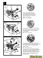
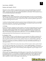
HYDRO TRANSAXLES - GT TROUBLESHOOTING
3
Symptom: Hydro Garden Tractor Won’t Drive.
Trouble shooting Cold starting for hydro (below 40 degrees F) after starting engine and before
driving , let the transmission warm up for (1) minute by placing the motion control lever in neutral
(N) position and releasing clutch/brake pedal.
1. Follow purge procedures described in step #7 on page 20 of this manual.
2. Place free wheel control in the drive position.
3. Check for proper installation and function of motion drive belt.
4. Verify that the axle engagement key is in place in both rear wheel hubs..
5. Verify motion control linkage is secure (all fastener are tight).
6. Verify proper oil level in transmission, remove oil level port plug and check oil level. Oil should
be at the bottom of the plug hole, but not running out.
7. Verify parking brake arm releases..
8. Test for system leaks ( fitting, hoses, seals, ect ) see test procedures.
PARKING BRAKE
The brake was factory set for specific running
clearance between the disc and pucks of 0.020".
Place a feeler gage between the disc and one puck,
if the clearance is not set properly remove the
cotter pin retaining the castle nut and set the correct clearance by adjusting the castle nut accordingly. Reinstall the cotter pin. Compliance brake
test: Check Brakes operation, tractor at full speed
in high gear must stop within six (6) feet or less
on level ground.
Test Procedure for System Leaks:
1. Remove vent from breather hose ( located at
the rear tractor on top of the hydro
transaxle).
2. Apply (5) to a maximum of (10) psi air pressure
to the hose.
3. If a leak is present, a puddle of oil should begin
to form under the transmission in less then (2)
minutes. Determine the origin of the leak.
4. If no leaks are found, change filter and oil.
5. If leak is found repair or replace defective
components.
6. Check level and top off with recommended oil.
7. Follow purge procedures as described in step #7
on previous page of this manual.
8. If tractor functions properly, check oil level and
top off with recommended oil if needed.
9. If tractor still won’t drive replace hydro/pump
(or) defective component) and follow
recommended start up purge procedures.
21
LEFT SIDE VIEW
PARKING BRAKE ARM
INSERT 0.020"
FEELER GAUGE
HERE
RIGHT SIDE VIEW
APPLY 5 TO 10 P.S.I. OF AIR
TO THE BREATHER HOSE
CHECK
FOR OIL
LEAKS IN
THESE
AREAS
(FITTINGS)
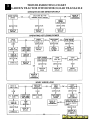
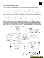
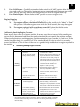
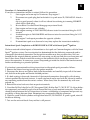
3
TROUBLESHOOTING CHART
GARDEN TRACTOR WITH HYDRO GEAR TRANSAXLE
22
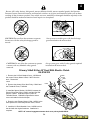
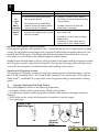
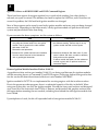
HYDRO TRANSAXLES - LT REPLACEMENT
WHAT YOU SHOULD CHECK BEFORE YOU REPLACE THE TRANSAXLE
3
Symptom: Tractor has loss of drive. No forward / reverse motion.
1. Check to see that the freeweel control is “DISENGAGED” position.
2. Make sure the motion drive belt is not worn , damaged or broken.
3. Vehicle should be on level ground before performing adjustments.
4. Verify that square axle key are installed in each wheel hub.
5. Was air trapped in hydro transaxle during shipment? (PURGE TRANSAXLE.)
6. Adjust the neutral position. Make sure shift lever linkage is tight.
7. Does hydro transaxle have enough oil ? Check oil level and add if needed..
8. Check the parking brake setting.
Set Parking Brake :
1. Adjust the nut onto brake bolt until tight or until the brake arm will not move.
CAUTION! do not over tighten the nut or damage may occur to the brake assembly.
2. Back nut off 2/3 turn (4 to 5 flats); place a 0.030" feeler gauge between the two outer discs to set
air gap.
3. Reinstall the cotter pin or second new nylon insert locking nut to lock the brake setting.
Bolt without hole requires use of Spring and 2 Locknuts
Bolt with hole requires the use of Spring and Cotter Pin
Back off nut 4 to 5 flats
(2/3 of one turn = 0.030")
Place 0.030"
Feeler Gauge here
23
3
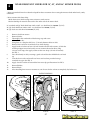
HYDRO TRANSAXLES - TROUBLESHOOTING
SYMPTOM: TRANSAXLE NOISY
Note:
The average Hydro-transaxle has a different sound level.
1. Check oil level as previously described, using a ruler for LT tractor and oil level port for GT.
2. Check cooling fan ( if applicable) for obstruction and/or broken fins, if fan blade is broken, replace, to keep the transaxle running at optimum performance keep the area clean. It’s recommended to use air to clean off debris. Although, using a garden hose (low pressure) with water is
acceptable as long as the transaxle is completely cooled down, for example clean with water before
the customer cuts the grass or after, as long as the tractor has sufficient time to cool down.
3. Check brake setting to ensure that it has the proper clearance and that the puck is not giving
resistance during freewheel. To check brake clearance; place a feeler gauge between the two outer
discs, if the clearance is out of range (.020"-.040" for LT tractor and .020"-.025" for GT tractors),
adjust the break retainer as needed to bring clearance into this range.
4. Check bypass valve linkage to insure that the bypass valve is fully opening and closing when the
actuator is activated.
5. Verify axle key is in place and in one piece.
HYDRO TRANSAXLES - LT TROUBLESHOOTING
SYMPTOM: ENGINE RUNS, TRACTOR WON’T DRIVE
1. Check bypass actuator to insure that it is in the “Drive” position.
2. Check belt integrity and that there is not excessive slippage on the input pulley. If the belt is
worn, dry rotten, broken, etc., replace and adjust.
3. Check oil level, the 310-0500 and 310-0750 holds approximately 80 ounces of 20W50 SG/CD
grade oil (or in cold weather 15W50 Mobil One synthetic oil is recommended) To check oil level:
remove vent hose and fitting. Put tape measure inside vent hole and measure oil level
On model 310-0500: the oil should be between 1.25" and 2.00" from top of housing.
On model 310-0650/0750: the oil should be between 1.00" and 1.75" from top of housing.
To add oil, remove vent hose and fitting. Add
RULER OR
oil until proper oil level for either type transaxle
TAPE MEASURE
is reached. Note: If oil level is found low, find
the cause of the problem, check the input seals,
bypass seals, and axle key. If needed, perform
the pressure test to find the leak.
4. If tractor still does not move, check shift
BREATHER
HOSE
linkage to be sure the shift lever is fully actuated.
5. Check brake and verify that the brake is
adjusted properly and the tractor freewheels
when the transaxle is in the transport position.
TO ADD OIL: Remove breather hose and
fitting. Add oil until proper oil level for
MEASURE
OIL LEVEL /
transaxle type is reached.
ADD OIL
HERE
24
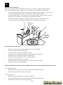
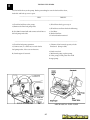
HOW TO ADJUST MOTION CONTROL LEVER ON VST PEERLESS HYDRO
The motion control lever has been preset at the factory and adjustment should
not be necessary.
If for any reason the motion control lever will not hold its position while at a
selected speed, it may be adjusted as follows:
•
Park tractor on a level surface. Stop tractor by turning key to "OFF" `
position and engage parking brake.
NOTE: Transmission should not be warm when making this adjustment.
Allow transmission to cool to airtemperature before making this adjustment.
To access the transmission adjustment, it will be necessary to remove the
battery and the battery box from tractor.
•
Raise seat and open battery box door. Disconnect BLACK battery cable
first, then the RED cable.
•
Remove battery and battery box from tractoras shown.
NOTE: When reinstalling battery box, ensure that battery acid drain tube is
routed toward the rear and is clear of the cooling fan.
•
Locate the access plug underthe cooling fan. This plug and surrounding
area must be cleaned to prevent contamination of internal parts during
this procedure. Before removing the plug, pack a cloth in the housing
pocket to absorb excess oil.
•
Using needle nose pliers, remove the access plug described above.
When the plug is removed, a small quantity of oii will flow out of the
transmission. This is normal and will not effect-transmission function.
•
Insert a #30 torx or 5/32 alien wrench into the access hole and locate the
adjustment screw. Adjust the screw clockwise 1/4 turn at a time to
increase motion control effort. An effort of 15-18 Ibs. at the motion
control lever knob is nommal.
NOTE: If for any reason the effort to move the motion control lever becomes
too excessive, reverse the above procedure by turning the adjustment screw
counterclockwise 1/4 turn.
•
Clean the access plug and insert it into position using the torx or alien
wrench.
•
Clean spilled oil from transmission and
WRENCH
ACCESS PLUG
reinstall battery box and battery
into tractor. When connecting battery be
sure to connect the RED bat
tery cable first. Road test tractor after
adjustment and repeat procedure
if necessary.
3
BATTERY ACID
DRAIN TUBE
COOLING FAN
HOUSING
POCKET
25
3
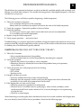
SECTION 11. VST TROUBLESHOOTING
The information on the following pages has been provided to help understand the internal operation of the VST. Do not use this information to attempt any internal repairs. Tecumseh's current
policy on hydrostatic transaxles that have internal failures is to replace the complete unit. This has
not changed. However, Tecumseh would like to provide a failure checklist to assist in making an
accurate evaluation of the complete tractor to eliminate any unnecessary replacements. Here is a list
of items to check and corrective actions to take.
To properly test the unit for power loss.
1.
Allow the unit to cool before trying the following steps.
2.
Put the shift lever in a position that is 1/2 of the travel distance from neutral to forward.
3.
Place the tractor on a 17 degree grade.
4.
Drive the tractor up the grade (without the mower deck engaged). The loss of power
experienced should be approximately 20%. This is considered normal. If the loss of power is
approximately 50%, this would be considered excessive.
5.
Bring the unit to neutral, shift into forward and note the response. Care should be taken to
move the lever slowly to avoid an abrupt wheel lift.
To detemmine if the problem is with the hydro unit, all external problem possibilities must be
eliminated. Here are some potential problem areas.
1.
Overheating: Heat can cause a breakdown in the viscosity of the oil which reduces the
pressure used to move the motor. Remove any grass, debris, or dirt buildup on the transaxle
cover and / or between the cooling fins and fan. Buildup of material will reduce the cooling
efficiency.
2.
Belt slippage: A belt that is worn, stretched, or the wrong belt (too large or wide) can cause
belt slippage. This condition may have the same loss of power symptom as overheating.
Typically, the unit which has a slipping belt will exhibit a pulsatina type motion of the
mower. This can be verified visually by watching the beTt and pulley relationship. It the
belt is slipping, the belt will chatter or jump on the pulley. If the belt is good, a smooth
rotation will be seen. Replace the belt and inspect the pulley for damage.
26
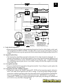
3
3. Leakage: The VST and 1800 Series have two oil reservoirs which can be checked for diagnostic
purposes. The first is the pump and motor expansion bellows, With a small diameter blunt or round
nose probe, check the bellows depth through the center vent hole. Proper depth from the edge of
that hole is 3-1/4 - 3-1/2 inches (8.25 - 8.9 cm).
The second chamber is for the output gears including the differential. FIRST make sure the tractor is
level, then remove the drain/fill plug. NOTE: Some units that do not have differential disconnect
will have two plugs. We recommend using only the primary plug. With a small pocket rule insert
until you touch bottom of case. You can then remove it and check for 1/4 - 3/8 inches (6.5 - 9.5 mm)
contact. This is full at its 8 oz. capacity of SAE EP 80W90 oil.
4. Low ground speed: If the linkage is not synchronized to absolute neutral, or the shift lever is not
properly fastened to the tapered control shaft, full forward travel may not be achieved. This may
cause a false reading and be misdiagnosed as a low power condition. This also could be caused by
the brake not releasing.
To detemmine absolute neutral, the hole in the tapered control shaft must face straight up and
down, at this point make sure the OEM linkage is in neutral. To properly fasten the control lever to
the shaft, torque the nut to 25-35 ft. Ibs. (34 - 48.3 NM) of torque with the shaft and the lever in
neutral.
When attaching the shifter arm to the shaft you must prevent any rotation during torquing. This
can be done by placing a long 5/16 bolt in the hole as shown in Illustration. Hold the bolt until the
tapers are locked and the nut torque is correct.
To make sure that the brake is not binding, drive the unit up a slight grade. Position the speed
control lever into neutral. The unit should coast backwards. If the unit does not coast back slowly,
the brake is not released from the brake disk. Adjust the brake linkage to release the brake completely when the foot pedal is released.
5. Hard to shift: Typically hard
to shift symptoms are not caused
by the hydrostatic unit. The shift
arm should move with relative
ease. Approximately 40-50 inch Ibs.
(4.48 - 5.6 NM) at the transaxle for
foot pedal units or 150-200 inch Ibs.
(16.8 - 22.4 NM) for hand operated
units. This varies depending on the
type of linkage. Binding may occur
in the linkage connections due to
rust or moisture. Lubricating these
connections and checking for bent
or damaged parts should resolve
hard shifting.
27
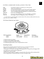
3
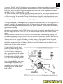
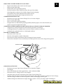
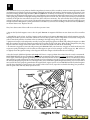
FRICTION PACK KIT INSTALLATION 71/143 799026
To install the friction pack kit first take these precautions. 1 ) Park the mower on a level surface. 2)
Make sure the parking brake has been set.
Raise the rear of the mower off of the ground and rest it on a stable support. Block the front wheels
to prevent the mower from rolling off the support. Remove the left rear wheel (in the operators
position) to expose the shifting linkage. Disconnect the turnbuckle shifting linkage at the pivot
point of the control arm and turn the control arm counter clockwise until it stops. To help accomplish this it may be necessary to place a 5/16 pin punch in the hole in the shifter shaft just behind
the control arm. Putting the punch in from the bottom side will provide increased leverage.
To mount the kit on the transaxle, angle the bracket so that it will clear the opening in the bracket
for the nut on the shifter shaft. Align the two bracket mounting holes up with the axle housing thru
holes. Fasten the bracket to the housing securing it with the two (2) 3/8" diameter self threading
bolts included in your kit.
Place the four (4) belleville washers on the remaining bolt so that the cupped sides face each other,
followed by a metal washer and a fiber washer. Place this assembly through the arced slot in the
bracket and the second fiber washer and the control arm securing the entire assembly with the
compression nut. Return the control arm to the neutral position and connect the shifting linkage.
Adjust the friction kit by using a torque wrench (beam style or needle style) on the shifter shaft nut.
The torque required to move the shaft should be between 150 - 200 inch pounds. If the shaft moves
at less then this setting tighten the nut on the friction kit accordingly or so that the shift lever stays
in position when driving up an incline. CAUTION: For safety reasons never operate equipment on
inclines greater then 15 deg rees .
28
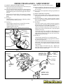
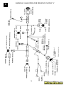
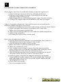
HYDRO TRANSAXLES - ADJUSTMENT
TO ADJUST MOTION CONTROL LEVER
The motion control lever has been preset at the factory and
adjustment should not be necessary.
If for any reason the motion control lever will not hold its
position while at a selected speed, it may be adjusted
at the friction pack located on the right side of transmission.
• Park tractor on level surface. Stop tractor by turning
ignition key to “OFF” position, and engage parking
brake.
LT (See Fig. 2):
•Adjust motion control lever by tightening adjustment locknut one half (1/2) turn.
GT (See Fig. 1):
•Place motion control lever in neutral (N) position.
•While holding locknut, loosen jam nut.
•Tighten locknut 1/4 turn.
•While holding locknut, tighten jam nut securely.
TURNBUCKLE/
LINKAGE
JAM NUT
LOCKNUT
LINKAGE
CONNECTING ROD
JAM NUT
FREEWHEEL
CONTROL ROD
JAM NUT
3
NOTE: If for any reason the effort to move
the motion control lever becomes too excessive, reverse the
above adjustment procedure by loosening locknut 1/
4 to 1/2 turn.
Road test tractor after adjustment and repeat procedure if
necessary.
TO ADJUST NEUTRAL POSITION
The Neutral (N) position of the motion control lever has
been preset at the factory and adjustment should not
be necessary.
If your tractor tends to "creep" when the motion control
lever is in the neutral (N) position, adjust the neutral
lever position as follows.
LT (See Fig. 2):
•Sit on the tractor in the normal operators position.
Start the engine and disengage the parking brake so
that the foot pedal is in the full up position.
•Move the motion control lever until the tractor no
longer moves forward or backwards. Stop the engine
and remove the key.
•Loosen the jam nuts on balljoint shift linkage and
twist connecting rod clockwise or counterclockwise
until motion control lever falls into the neutral slot.
Tighten jam nuts and retest.
GT (See Fig. 1):
•Place motion control lever in neutral position.
•Locate turnbuckle/linkage at top right corner of drawbar and loosen jam nuts.
•Place concrete block under drawbar to lift rear wheels
off ground. Start engine and turn linkage connecting
rod clockwise or counterclockwise until the rear tires
stop turning.
•Stop the engine and remove the key. Tighten jam
nuts and retest for creeping with fastest engine rpm
from both forward and reverse.
DRAWBAR
FIG. 1
MODEL 0750
TRANSAXLE
ROD NUTS
(IF EQUIPPED)
BALLJOINT
SHIFT
LINKAGE
JAM NUT
CONNECTING LINK
ADJUSTMENT
LOCKNUT
JAM NUT
FREEWHEEL
CONTROL
ROD
MODEL 0500
TRANSAXLE
FIG. 2
29
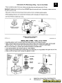
3
NEUTRAL ADJUSTMENT FOR AUTOMATIC DRIVE CONTROL LEVER
1. Place the tractor on a smooth paved level surface.
2. Loosen Adjustment Bolt in front of the right rear wheel, and lightly tighten using a 1/2" wrench.
3. Start Engine and move Lever until tractor does not move forward or backward.
Hold Control Lever in that position and do not move. Turn the engine off.
4. While holding the Control Lever to keep it from moving, loosen theAdjustment Bolt . Move the
Control Lever to the position indicated for Neutral on the fender. Tighten Adjustment Bolt
securely.
FINE TUNE THE NEUTRAL ADJUSTMENT ON AUTOMATIC DRIVE
1. Place the tractor on a smooth paved level surface.
2. Loosen the Adjustment Bolt using a 1/2" wrench. If the tractor is creeping forward, move the
Control Lever forward 1/4 to 1/2 inch. Move the Control Lever rearward 1/4 to 1/2 inch if the
tractor is creeping backwards. Tighten the Adjustment Bolt securely.
3. Start engine and test from both forward and reverse.
4. If tractor still creeps, repeat step # 2 until satisfied.
NOTE: If additional clearance is needed to get to adjustment bolt, move mower deck height to the
lowest position.
NEUTRAL ADJUSTMENT FOR GEAR DRIVE SHIFT LEVER
1. Place the tractor on a level surface.
2. With the engine off and the parking brake disengaged, push the tractor from behind while shifting
gears.When the tractor rear wheels move freely, the transaxle is in neutral. Leave in this position.
3. Loosen Adjustment Bolt in front of the right rear wheel,using a 1/2" wrench. Position the Lever
in the position indicated for Neutral.Tighten Adjustment Bolt securely.
NOTE: If additional clearance is needed to get to adjustment bolt, move mower deck height to the
lowest position.
30
4
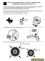
TRACTOR MOWER DECK LEVELING PROCEDURE
COMMENTS FOR QUALITY OF CUT
PROPER ADJUSTMENTS TO MOWER DECK LEVELNESS AND ENGINE RPM ARE IMPORTANT FOR OPTIMUM MOWER PERFORMANCE AND QUALITY OF CUT.
(WATCH OUR NEW DESK LEVELING VIDEO PART# 168695)
*Customers should be instructed to always mow at full engine speed. There is a detent in the throttle control that marks
this position. The throttle and carburetor should be properly adjusted to provide maximum allowable full engine speed
when mowing. The correct allowable full engine speed setting are as follows.
On tractor 1992 and newer with a vented deck, 3350 RPM + or - 50 RPM.
On tractor 1991 and older with a standard deck, 3550 RPM + or - 50 RPM.
FULL ENGINE
SPEED IN
DETENT
FAST
* Ground speed: Customer should select proper travel speed for mowing conditions and shift transaxle down to a slower
ground speed if necessary to achieve a desired quality of cut.
* Be sure tires are properly inflated before making any adjustment to mower. Inflate tires to operating PSI shown on
sidewall of tires or, to specification in product owners manual.
CHECK TIRE PRESSURE
REAR TIRES
10 TO 12 PSI
FRONT TIRES
14 PSI
31
* Gauge wheels should be assembled so they are slightly off the ground when mowing. Gauge wheel should
not be rolling on the ground continuously when mowing on level ground. Gauge wheels adjusted too low will
cause excessive rake.
4
GUAGE
WHEEL BAR
SHOULDER
BOLT
GUAGE
WHEEL
GUAGE
WHEEL
CLEVIS PIN
* Replace worn or bent blades. Check blades to be sure they are straight and have a sharp edge.
* If bottom edge of mower deck is worn or damaged, making measurements difficult, make all adjustments and
measurements at the tip of the blades. Be sure blades tips are positioned appropriately for each adjustment check ( towards
outside for side-to-side check and front-to-back when checking rake).
* Mower should be level side-to-side or within 1/8" of each other and have a slight rake angle front-to-back 1/8" to 1/2"
lower in the front than in the rear, optimum setting at 1/4". Make mower adjustment in the high cut position.
LEVEL DECK SIDE-TO-SIDE
NOTE: DECK
SHOULD NOT GO
LOWER THAN 1 1/2"
AT BLADE TIPS IN
LOW CUT POSITION.
ADJUST
THESE NUTS
FOR SIDETO-SIDE
LEVEL OF
DECK.
BOTH FRONT LINKS MUST BE EQUAL IN LENGTH.
SIDE-TO-SIDE SHOULD BE SET LEVEL OR WITHIN 1/8" OF
EACH OTHER.
SLIGHT RAKE ANGLE FRONT-TO-BACK
FRONT OF
TRACTOR
• ADJUSTING LINKS TO SHORTER LENGTH REDUCES DECK
RAKE.
• ADJUSTING LINKS TO LONGER LENGTH INCREASES DECK
RAKE.
32
SET RAKE AT 1/8" TO 1/2" WITH OPTIMUM SETTING AT 1/4".
NOTE: EXCESSIVE DECK RAKE MAY CAUSE PREMATURE BELT
FAILURE. ALWAYS CHECK DECK RAKE WHEN REPLACING
THE MOWER DRIVE BELT OR WHEN LEVELING THE DECK.
4
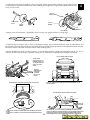
DIFFICULT TO LEVEL MOWER DECKS.
1. Verify tractor frame is level by measuring the distance from frame to the ground on level flat surface.
Frame should measure the same or be within 1/8" of each other. If frame measures more than 1/8" try the
following.
2. Reduce tire pressure to correct PSI rating on tires. 14 lb front, 10 to 12 lb rear.
3. Level the tractor frame: Loosen (do not remove) the thread rolling screws and the two bolts on each "L" shaped transaxle
mounting bracket where the bracket mounts to the tractor frame. Loosen (do not remove) the two bolts on each torque strap
where torque strap mounts to the tractor frame. Lift the rear of the tractor up and down until tractor sits level. Retighten
thread rolling screws and all bolts previously loosened.
OLD HATCHET DESIGN
ADJUST TIRE
PRESSURE
22
4
CURRENT DESIGN
CHECK LEVEL OF TRACTOR FRAME. FRAME SHOULD
MEASURE SAME OR BE WITHIN 1/8" OF EACH OTHER.
3
ADJUST THESE NUTS FOR SIDE
TO SIDE LEVEL OF DECK.
TORQUE
STRAP
5
FRAME BRACKET
138441
ANTI-SWAY BAR KIT
DECK BRACKET
1992 TRACTOR
LEVEL THE TRACTOR FRAME
4. Lawn tractor built 1992 and 1993 with the old style hatchet design suspension system can make side-to-side leveling
difficult. Suspension kit #152287 (71/917) can be installed to make side-to-side leveling adjustment easier by turning two
adjusting nuts.
5. 38" and 42" mower decks built in 1992 can sway side-to-side when cutting. This can be corrected by installing Anti-Sway
kit #138441 (71/917).
33
4
WHAT TO REMEMBER WHEN REPLACING A BELT
Any time you are replacing a broken belt, try to determine the root cause of the belt failure. Failure
to determine the root cause of the belt failure and correcting it, may cause repeated service calls.
* Are you installing the correct belt number for the model you are working on ?
* Is there grass build up, sticks, or trash on top of the mower deck that is causing the belt to jump
off the pulley or break? Instruct the customer to keep the deck top free from build up of debris.
* Are the Mandrel or Idler pulleys Damaged or Worn? Inspect the Mandrel pulleys to make sure the
pulley grooves are not bent or damaged. Inspect all Idler pulleys to be sure they are not damaged or
the idler bearings are not bad or frozen up and need to be replaced.
* The mower drive belt is stretched and slipping when mowing. Each deck has an adjust trunion on
the mower deck engagement lever that can be adjusted to extend the belt life on a stretched belt.
* Is the Mower Deck set with excessive deck rake that is causing short mower belt life?. Excessive
Deck rake on a mower will cause the belt to run at much higher than normal belt angles, which will
cause the belt to wear out or fail prematurely. All Decks should have a slight rake angle front-toback 1/8" to 1/2" lower at the front blade tip than at the rear of the blade, with an optimum or best
setting at 1/4" rake.
To loosen a tight belt turn the clutch
rod trunion in clockwise.
CLUTCH ROD ASSY.
To tighten a loose belt, turn the clutch
rod trunion out counter clockwise.
CLUTCH ROD
A
TRUNNION
FIG. 1
(A) Clutch Rod Length
38" clutch rod 10.00"
42" clutch rod 10.40"
46" clutch rod 9.38"
ER
W
O
M
R
E
AK
LE
G
AN
H
IG
34
H
FIG. 2
O
TO
3/4"
or Higher
4
IDLER
PULLEYS
ELECTRIC
CLUTCH
MANDREL
PULLEY
42" mower deck 1992 TO 1993
OLD STYLE ARCH SUSPENSION
TEE PATH BELT ROUTE WITH
TWO IDLER PULLEY. USE DECK
BELT 71/917 #130969
SIZE 1/2 X 11/32 X 92.41
MANDREL
PULLEY
MANDREL
PULLEY
IDLER
PULLEY
42" mower deck 1994 NEW STYLE SUSPENSION TRI-PATH BELT ROUTE WITH ONLY
ONE IDLER PULLEY. USE DECK BELT
71/917 #140067
SIZE 1/2 X 11/32 X 86.62
MANDREL PULLEY
CLUTCH ROD
CLUTCH
LEVER
RETAINER
SPRING
ENGINE
PULLEY
SUSPENSION
ARMS
FRONT
LINK
42" mower deck 1995 to 1998 NEW STYLE
SUSPENSION TEE PATH BELT ROUTE WITH
TWO IDLER PULLEY. USE DECK BELT
71/917 #144200
SIZE 1/2 X 3/8 X 88.38
RETAINER
SPRINGS
(BOTH SIDES)
TRACTOR WITH 42" DECK BUILT FROM
1992 THRU 1994, THAT REQUIRE THE DECK
HOUSING TO BE REPLACED, WILL BE
UPDATED WITH OUR CURRENT 42" BELT
#144200, WHICH IS SUPPLIED IN THE
HOUSING KIT.
RETAINER
SPRING
ANTI-SWAY BAR
RETAINER
SPRINGS
(BOTH SIDES)
35
4
. Be sure ALL safety devices, belt guards, mower deflector shields, mower mandrel guards, the Operator
Presence System, electrical harnesses and interlock switches are in place and functional when you are done
working on the customers product. Parts which are worn, modified, or damaged should be repaired; or the
product should be made non-functional until repairs are completed.
CAUTION: Do not allow the customer to operate
the mower with the safety discharge guard removed.
Always mow or mulch grass with the discharge
guard attached to the mower deck.
CAUTION: Do not allow the customer to operate
a mower with any Mandrel safety guards
removed.
Always mow grass with all safety guards required
installed on the mower deck.
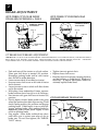
Primary V-Belt Kit for 46” Deck With Electric Clutch
Kit #166109
1. Remove the LH Deck Mandrel Cover, 145059 and
the current Primary Mower V-Belt, 139573 from the
deck. Discard the
v-belt.
17490628
19131616
156493
19132203
156086
2. Remove the primary Drive Idler Pulley, 156493 and
the Threadroll Screw, 17490628.
145059
3. Install the Spacer Washer, 19132203, between the
Primary Drive Idler Pulley, 156493, and the Idler Belt
Keeper, 156086. Hold belt keeper in place as
Threadroll Screw, 17490628 is tightened to ensure
correct orientation of the belt keeper.
4. Route the new Primary Mower V-Belt, 148763, in the
same path as the old Primary Mower V-Belt, 139573.
5. Install the LH Deck Mandrel Cover, 145059 back on
the deck with the original hardware. Installation is
complete.
NOTE: 46” manual engagement mower deck uses primary belt #158818.
36
148763
4
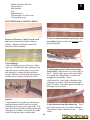
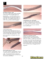
WEAR-RESISTANT LINERS FOR 38", 42", AND 46" MOWER DECKS
* Wear resistant deck liners have been developed for those customers who are using their mower deck under harsh, sandy
conditions.
* Wear resistant deck liners help:
* Make the mower deck housing more resistant to sand erosion.
* Reduce buildup of materials that stick to the under side of the mower deck.
38" standard and QC decks built from 1985 to 1997 - use deck liner kit #151881 (71/917).
42" QC decks built from 1992 to 1997 - use deck liner kit #151882 (71/917).
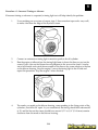
46" QC decks use deck liner kit #157463 (71/917).
1.
2.
3.
4.
5.
6.
7.
8.
9.
10.
11.
12.
13.
Remove deck from tractor.
Remove blades.
Thoroughly clean underside of deck using soap and water.
Allow deck to dry.
Using liner as a template drill 12 ea. 7/32 inch diameter holes in deck.
Remove liner and clean it and deck of any drill shavings.
Apply beads of sealant on liner 1/4 inch outside of both circle cutouts, (if deck has
teardrop stripper instead of round, cut out section indicated on liner using
scissors or tin snips, then apply sealant to this new shape 1/4 inch all around).
See FIG. 1.
Press liner firmly in deck, ensuring a good seal and that the drilled holes are lined
up.
Turn deck on its side and install steel rivets and washers provided using a
standard rivet gun. See FIG. 2.
Apply a bead of sealant all around the liner outer lip per illustration. See FIG 3.
Reinstall blades.
Reinstall deck.
After installing liner instruct customer to wait 2 hours for the sealant to completely dry before use.
PATENT PENDING
FIG. 1
FIG. 2
37
FIG. 3
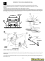
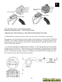
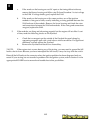
42" DECK MANDREL PAD REINFORCEMENT RING
KIT NO. 151786
4
Before installing this mandrel pad reinforcement ring, the mandrel pad should be checked to see if it is
bent. NOTE: Blades must be checked for straightness before checking to see if the mandrel pad is
bent. Straighten or replace bent blades. To check for bent mandrel pad, rotate the blade tips around
to check all four blade tips at the center of the deck. There should be no more than 1/8" difference
between the tips. If there is more than 1/8" difference, check to see if the left hand mandrel pad is bent
inward toward the center of the deck. If housing pad is bent, you should use the deck straightening tool
DS-100 to straighten the housing pad.
How to use the mower housing mandrel pad straightening tool Part Number DS-100 (92/150).
• Before attempting to use this tool, be sure the mower blades are straight.
• Note the direction that the housing mandrel pad bent when the mower blade hit an object and line up the straightening
tool to pull back in the opposite direction. The deck will most likely be bent in the direction that the belt was pulling, toward
the idler pulley, when the blade hit something and came to sudden stop.
• Wrap the chain around the mandrel housing shaft and fasten them together.
• Turn the nut on the eyebolt and watch the mandrel and blade move until the blades are even.
• It may be necessary to pull the mandrel pad past level to compensate for any spring back.
• Be careful not to pull the mandrel pad too far past level.
• The mandrel pad reinforcement ring should be installed to help prevent future bending.
FRONT
DS-100 PAD STRAIGHTENING TOOL
TYPICAL BEND AREA
TYPICAL TOOL
PLACEMENT
LOCATION
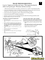
To Install Mandrel Pad Reinforcement Ring
•
•
•
•
•
•
•
•
MANDREL
GUARD
Remove mandrel guard.
Remove belt from mandrel pulley.
Remove mandrel pulley nut and pulley.
Remove and discard the three (3) mandrel mounting
bolts.
Position reinforcement ring over mandrel pad and
install new mounting bolts supplied with this kit. Tighten
all bolts securely.
Reinstall mandrel pulley and nut. Tighten securely to
55-65 ft. lbs. torque.
Reinstall mandrel guard and V-belt around pulley.
Make sure belt is in all pulley grooves and inside all
belt keepers.
NUT
MANDREL PULLEY
WASHER
NEW MOUNTING BOLTS
Part No. 138776
REINFORCEMENT RING
MANDREL
38
4
SPACER
ORDER KIT
71/917 #149049
TENSIONING SPRING
ATTACHMENT
LOCATION
TENSION
SPRING
CAM ROLLER KIT
71/917 #149049
IDLER PLATE
FIG.1
BRAKE
CAM
ROLLER
(2X)
FIG.2
FIG. 1 - Tensioning spring on electric clutch 44"/50" decks break - Solution - order kit 71/917
#149049
FIG. 2 - Mower engagement lever binding and/or not completely disengaging on mechanical clutch
42" decks - Solution - install brake cam roller kit 71/917 #151785.
FIG. 3 - Idler suspension bracket breaks. Avoid replacing 44" & 50" mower housing order kit 71/917
#150021.
KIT 71/917 #150021
RH SUSPENSION
BRACKET
WASHER
13/32x3/4x12Ga.
(INCLUDED)
HEX BOLT
5/16-18x1-1/4
(INCLUDED)
FIG.3
39
TENSION ARM
AND REINFORCEMENT
PLATE ASSY.
4
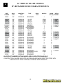
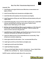
36" THRU 50" BLADE LISTING
BY RETAINER HOLE CHARACTERISTICS
PART
NUMBER
DECK
SIZE
CONSTRUCTION
TYPE
25645
36"
REGULAR
138970
138497
139774
134148
38"
38"
38"
38"
PREMIUM
REGULAR
PREMIUM
REGULAR
121263X
25036
104418X
25741
134998
38"
38"
38"
38"
38"
REGULAR
REGULAR
REGULAR
REGULAR
REGULAR
CROSS/BAGGER
138971
138498
139775
134149
42"
42"
42"
42"
PREMIUM
REGULAR
PREMIUM
REGULAR
HI LIFT
HI LIFT
MULCH
MULCH
130652
25034
25742
44"
44"
44"
PREMIUM
REGULAR
REGULAR
25321
25322
42"
48"
REGULAR
REGULAR
163819
157033
159705
46"
46"
46"
PREMIUM
PREMIUM
PREMIUM
137380
156468
121798X
25743
50"
50"
50"
50"
PREMIUM
PREMIUM
REGULAR
REGULAR
DECK
TYPE
STANDARD
HOLE(S)
BLADE
RETAIL
BOLT(S) NUMBER
1
1
STAR
STAR
STAR
STAR
1
1
1
1
71-24651
71-24671
71-24654
71-24692
1
1
1
3
1
1
1
1
2
1
71-24673
71-24691
STAR
STAR
STAR
STAR
1
1
1
1
71-24652
STANDARD
STANDARD
STANDARD
STAR
1
3
1
1
2
71-24678
71-24677
STANDARD
STANDARD
3
3
2
2
STAR
STAR
STAR
1
1
1
71-24004
71-24006
STAR
STAR
1
3
1
1
1
2
71-24005
HI LIFT
HI LIFT
MULCH
MULCH
BAGGER
STANDARD
STANDARD
MULCH
MULCH
HI LIFT
BAHIA
STANDARD
STANDARD-THICK
STANDARD
STANDARD
71-24655
71-24676
BLADE PART NUMBERS WITHIN SHADED AREAS ARE INTERCHANGABLE.
CONSTRUCTION - BLADES INDICATED AS PREMIUM ARE MADE OF BETTER STEEL WITH
A BETTER HEAT TREAT PROCESS TO RESIST SAND ABRASION
40
4
OPTIONAL TRACTOR MOWING BLADES THAT CAN BE USED IN PLACE
OF ORIGINAL EQUIPPED BLADES TO IMPROVE QUALITY OF CUT UNDER DIFFERENT MOWING CONDITIONS.
HI LIFT BLADE
3 IN 1 MULCHING BLADE
38” BLADE * Part Number 134148 Original Equipped 38” Standard 3 in one mulch blade.
1. Use 139774 Premium 3 in one mulching blade for better wear when mulching.
2. Use 138497 Standard Hi lift blade for better bagging , especially in wet
conditions.
3. Use 138970 Premium Hi lift blade for better wear when bagging in heavy
or wet condition.
42” BLADE * Part number 134149 Original Equipped 42” Standard 3 in one MULCH blade.
1. Use 139775 Premium 3 in one Mulching for better wear when mulching.
2. Use 138498 Standard Hi lift blade for better bagging , especially in wet
condition.
3. Use 138971 Premium Hi lift blade for better wear when bagging in heavy
or wet condition.
46” Blade
* Part Number 152443 Original Equipped 46” Premium 3 in one MULCHING blade.
1. Use 157033 Premium Hi lift blade for better bagging , especially in wet
conditions.
2. Use 159705 Bahia blade for better quality of cut on pasture type grassES
OR Bahia GRASS.
50” Blade
* Part number 137380 Original Equipped 50” Premium Hi lift blade.
1. Use 156468 Premium Hi lift thick blade FOR BETTER WEAR.
41
Why use O.E.M. v-belts?
5
O.E.M. stands for Original Equipment Manufacturer. This is the company that made the product,
in this case with the v-belt drive. O.E.M. v-belts are designed for the characteristics of the individual drive system. This means the v-belt will last longer and work properly. OEM v-belts
should be used only in the drive for which the v-belt was designed.
Aftermarket V-belts fall into four categories: auto parts v-belts, fractional horsepower electric motor
v-belts, lawn and garden v-belts, and agricultural replacement v-belts.
Auto parts V-belts are designed specifically for cars and trucks. These v-belts have polyester cords
which are designed to shrink when the v-belt gets hot as it starts to slip. These v-belts have minimal covers and only a few cords. They are designed for low horsepower at high RPM with NO
misalignment of pulleys.
Fractional Horsepower Electric Motor v-belts usually have designations like 4L or 3L. The ‘L’ is for
light duty. Normally this v-belt is for one (1) horsepower or less and has polyester cords.
Lawn and Garden aftermarket replacement v-belts normally have kevlar cords and an aggressive vbelt cover. These v-belts may or may not give a good service life. The aggressive v-belt cover will
usually grab in the drive system. This may result in front end lift off (wheelies) or may result in
the drive pulley burning a section of the drive cover off. The aftermarket v-belts are normally found
in one inch increments. If a v-belt is too long, it’s life is shortened.
If the aftermarket v-belt is too short, the v-belt may not declutch when needed.
Agricultural aftermarket replacement v-belts are similar to the Lawn and Garden replacement vbelts but with larger cross section and are designed for larger pulley diameters.
F.H.P. uses only OEM v-belts which have the correct length, v-belt cover, and cord construction.
The correct length maximizes the service life of the v-belt. The v-belt cover specified gives the
slippage or traction required for the drive. The v-belt cords are appropriate for the force the v-belt
will transfer and the shock loads expected.
How are OEM v-belts customized?
OEM v-belts are designed for that specific drive application. Many things can be changed.
The v-belt is a wedge. The power is transmitted through the angled sides of the v-belt.
The angle of the side walls is different on some OEM v-belts. This is done to achieve a desired
drive characteristic. For this reason, it is not a good idea to use an OEM v-belt in a place other than
its designated application.
There are different belt cords that can be used.
v-belt will transfer in a specific application.
The is cord selected for the load or force the
Kevlar is the strongest cord which will normally be a Yellow color. Kevlar is by weight stronger
than steel and will not stretch. It is widely used in products that require strength and light weight
such as bullet proof vests.
42
5
Fiberglass cord may be used where the maximum strength will not be needed but without stretch.
The fiberglass cord will be a reddish brown on source 917 tractors.
Polyester filament cord may be used where there should be a moderate force. The Polyester filament is dyed and may be different colors from different manufacturers. On source 917 tractors and
tillers, the Polyester filament is a cream/white color. Polyester filament cords will shrink if they
get hot and can stretch. Polyester is a good shock absorber and may be used in applications where
there are high shock loads and length stability is not critical.
Polyester staple cord or rayon cord are used in lesser quality v-belts and are often found in aftermarket belts. These cords are not used on source 917 tractors.
The v-belt cover must also be matched to the application.
A White Cover is specified for increased slippage or less front end lift off (wheelies). The White
Cover v-belt is a cotton/polyester blend. If you find one of these v-belts failed with a hard black
residue in the engine pulley, remove the residue or replace the pulley. Never replace a white
cover v-belt with a black cover v-belt. CRT tillers must have a white cover v-belt to allow the vbelt drive to slip when the tines hit obstructions. On CRT tillers, the White Cover v-belt also eliminates tine creep and wheel creep.
A Salt & Pepper Cover is used when increased v-belt traction is needed.
A Black Cover is used on v-belt drives requiring even higher traction for mower drives and tillers.
In operation this v-belt is black and sticky from rubber in the canvas v-belt cover. Most aftermarket
v-belts have this type of cover.
A Cut Side V-belt with no cover may be used in some applications. A cut side v-belt is very aggressive engaging the pulley.
What to check when a v-belt is replaced.
There are many reasons that a v-belt fails. If a problem caused the failure of one
v-belt, that problem must be corrected or the new v-belt will also fail in a
short period of time.
Check v-belt alignment in the drive - add "pulley".
Check mower rake to determine proper mower v-belt alignment
Check for a bent mower deck causing improper alignment
Check for bent idler pulley brackets
Check for binding idler pulleys
Check mandrel shaft for bearing wear or binding
Check pulleys for wear and for deformation
Check v-belt guards and v-belt guides for worn spots against v-belt
Check for obstructions in mower decks (including grass buildup)
43
Check the failed v-belt for:
Wear patterns
Deformation
Cuts
Burned section
Oil saturation of v-belt cover
V-belt pulled apart
5
ILLUSTRATIONS of FAILED V-BELTS:
V-belt Cut from installation by Prying v-belt
over pulley Replace v-belt with correct installation procedure.
Excessive Oil causes V-belt Cover to swell
Belt looks normal, but belt feels sticky or
spongy. Replace v-belt and correct the
reason for the oil problem.
V-belt Slippage
V-belt drive lacks proper tension or v-belt is
worn out. The belt may show glazing on the
sidewalls, excessive heat, fabric worn from
belt sidewalls, or sidewall fabric polished
smooth. Measure v-belt length and compare
to dimension in newest accessories book.
V-belt bottoms out in Pulley or Wear from
rough Pulley V-belt worn away at the sides of
the ‘v’. Check pulley grove and v-belt width.
Also check the v-belt pulleys or small rock
wedged into the pulley. Worn
v-belt sidewalls, v-belt rides at bottom of the
pulley grove, replace v-belt and replace damaged ‘V’ pulley. The pulley groove should not
be rough, rusty, or worn.
Rupture
A ruptured belt is caused by an obstruction
coming between the belt and the v-pulley
putting excessive pressure on the cords. The
cords will fracture inside the belt and the belt
will separate. Unlike a shock load, the cords
will be frayed and fuzzy on both ends.
V-belt Abrasion from idler locked up The vbelt will be worn across the width of the belt.
The material will be carbonized and
show
cracks.
44
5
Spin Burn section of v-belt
The V-belt is tightly held by pulleys and idler
spring tension when engaged against the
engine pulley. A mower in tall grass in a
lowered position may experience a spin burn
when the v-belt is engaged. Or check for a
long v-belt. If a newly installed v-belt is too
short, it may spin burn when disengaged.
V-belt Rubbing on a v-belt guide
A v-belt worn on one side will usually be
caused by a v-belt guard or too close to the vbelt. This can also be caused by a stick or rock
in a v-belt guide. In some cases the fabric
cover way be frayed.
V-belt turned in drive
The entire v-belt can be deformed when the
belt turns in a drive. The belt cross section will
appear deformed and instead of the belt being
an oval it will be like a ‘potato chip’. If this
belt is reinstalled, it will quickly turn in the
drive again.
Shock Load fracture of V-belt
The v-belt is ‘broken’ or pulled apart. It is not
a smooth cut that you might get from a v-belt
guide. The material fracture is rough and
cords may be hanging out of one or both ends.
The cords are well defined.
Vibration in v-belt drive system
If there is vibration in the drive system,
footpedal motion, or mower deck motion,
check the v-pulleys. A pulley can cause vibration from a ‘cam’ action if it is deformed wider
or narrower at one point. This can also happen
if the sides of the pulley are separating from
the hub of the pulley. It may not be noticeable
unless the drive system is engaged with the
engine off.
45
6
BATTERY SECTION ON
BATTERY FAILURE DETERMINATION AND TESTING
When a battery is replaced, we need to determine the reason the old battery failed. The battery is often the symptom, not
the problem. There will be additional service calls until the real problem is found. And until then, batteries will be
unnecessarily replaced. 50 percent of all replaced batteries can be charged, tested, and reused.
Reasons for battery replacement include: bad electrical ground, battery cable connections corroded, battery internal
problem, engine hydraulic lock, improper operation of the engine compression release, electrical drain or short in wiring
harness or component, engine charging system problem, engine RPM to slow during operation, or the battery was not fully
charged when installed. All storage batteries discharge when not being charged and the discharge rate increases as the
temperature rises. Batteries in storage for more than 6 months will need charging before use.
Open Circuit Voltage Test
The Open Circuit Voltage Test will tell the state of charge of the battery. A battery should have a state of charge of 50
percent (12.20 Volts) for accurate troubleshooting. Select the meter scale for DC Volts. Connect the negative meter lead to
the negative battery terminal; and the positive lead to the positive battery terminal.
DC VOLTS
*
*
*
*
If 11.7 Volts or less; extensive charging required to recycle this battery—replace battery.
If 12.2 Volts or less, the battery charge is marginal, charge at 6 to 10 amps or exchange the battery and save for
recycling.
If 12.2 to 12.5 Volts, battery is good, additional charge helps
If 12.6 Volts or above the battery is fully charged
46
6
CHECK BATTERY GROUND
The battery must be grounded to the frame and the engine for electrical components and charging to
work. Place the ignition switch in off position. Use a continuity tester or Meter on OHMs scale.
*
Test for the ground to frame. Place one meter lead on negative battery terminal and the other on
a known good ground to the frame. If no continuity, correct before proceeding
*
Test for ground to engine. Place one meter lead on negative battery terminal and the other on a
good ground on the engine. If no continuity, correct before proceeding.
*
clean battery terminals and battery cable ends until metal is bright. Coat terminals with a
non-metalic grease or commercially available battery terminal protection product.
POSITIVE
CABLE
OHMS
TO FRAME
GROUND OR
TO ENGINE
GROUND
SITE TECHNICIAN LOAD TEST
*
*
*
*
*
*
*
*
The battery must pass Open Circuit Voltage Test at 12.5 volts or higher.
Remove spark plug wire from spark plugs
Put meter on D.C. voltage scale larger than 15 volts.
Attach meter test leads to battery terminals. Like Open Circuit Voltage Test.
Watch meter while cranking the engine for 10-15 seconds.
If the battery voltage drops below 7.2 volts while cranking,
the battery requires charging or is defective
If the battery holds 8.5 volts at the end of 10-15 seconds, the battery is good.
Reattach spark plug wire to Spark Plugs
CHECK FOR PROBLEMS WITH ENGINE COMPRESSION RELEASE OR CYLINDER HYDRAULIC LOCK
*
*
The symptoms include:
The battery may only spin the engine fast enough to start when fully charged
The battery may not turn the engine starter motor
This may result in:
*
*
*
Batteries not fully charged will be unnecessarily replaced
There will be multiple service calls resulting in unneeded battery replacement
Starter Motors may also be unnecessarily replaced
47
6
CHECK FOR CYLINDER HYDRAULIC LOCK FIRST
*
Engine Starter Motor will not crank over the engine
*
Remove engine Spark Plug.
*
If fluid comes out of spark plug opening
The fluid would not allow the piston to go to the top of the cylinder
Check dipstick for crankcase level, if high, change oil and spark plug.
If oil smells of fuel, check carburetor float, needle, and seat.
If will not start, proceed with Compression Release Test.
COMPRESSION RELEASE TEST
*
The battery must pass Open Circuit Voltage Test at 12.2 volts or higher.
*
Remove engine Spark Plug.
*
Place a rag over the spark plug opening
*
If engine turns over without the spark plug installed, check for proper valve clearance before you
replace or repair the compression release
SYMPTOMS OF WIRE HARNESS OR SWITCH ELECTRICAL CURRENT LEAKAGE PROBLEM
*
components or wiring leak electrical current allowing the battery to discharge
*
a discharged battery is a problem when tractor has not been used for several days.
*
multiple battery replacements due to a discharged condition
ELECTRICAL LEAKAGE TEST
*
Place meter on DC volts scale.
*
Place the tractor ignition switch in off position.
*
Place meter test leads at black battery cable and negative battery terminal.
*
If more than 1.0 volts DC shows on the meter, find and repair the source of the voltage leak to ground.
POSITIVE CABLE
DC VOLTS
CHARGING SYSTEM TEST
*
The battery must pass Open Circuit Voltage Test at 12.20 volts or higher.
*
Start Engine
*
Place at full throttle and check engine R.P.M.s with a tachometer (3500)
*
Place meter on D.C. Voltage scale 15 volts or higher.
*
Attach the meter test leads to the battery, like in Open Circuit Voltage Test.
*
If voltage when the engine is running at full speed exceeds voltage when the engine is off (Open Circuit Voltage);
and if the voltage exceeds 12.6 and is rising after 1 minute, the charging system is good.
*
Additional diagnostic information on engine charging systems is in last years book, ‘BACK TO BASICS’ I.
48
6
BATTERY RECYCLING
Why Recycle batteries? Many batteries are replaced so the service call can be completed. Most replaced batteries are
only discharged, and only need a good charging to be serviceable. Why throw away functional parts that can be recycled?
Recycled batteries can be used on MA calls and can reduce parts costs to your service center.
Battery plates are made from lead-alloy. Lead is toxic. Recycling batteries reduces environmental
pollution.
PROCEDURES FOR RECYCLING BATTERIES.
Wear protective equipment when working with batteries. Goggles or glasses with face shield should be used to protect
eyes anytime you are handling batteries. A plastic apron or lab coat will protect your clothes. Rubber gloves should
be worn when handling batteries.
Do a visual check of the battery case and the battery terminals for damage. If damage is found, dispose of the battery
following E.P.A. regulations.
LOOSE
POSTS
Check the electrolyte level. If the cell at negative post of the battery has less than 3 inches of electrolyte, dispose of battery
properly. If electrolyte is not 1/4 inch over battery plates in any cell of the battery, add water to the proper level.
NOTE: Checking the electrolyte is not possible with Maintenance Free Sealed Batteries. If vent plugs are not easily
removable, skip this step.
49
Clean the battery exterior. Use a solution of one cup baking soda to 1 gallon of water, and stir. Do not get
cleaning solution in the battery cells. Use disposable wipes to clean and dry battery.
6
Charge the batteries. Use a CONSTANT CURRENT CHARGER set at 8 to 10 amps for 2 to 4 hours. It may be necessary
to adjust charge rate up after 30 minutes.
Test the batteries with a Load Tester like the MILTON BT1260 Connect the Test Leads to the appropriate battery terminals.
Actuate the Load for 2-3 seconds to eliminate any surface charge If voltage drops below 7.2 volts, discontinue test
immediately and properly dispose of battery for internal failure. Note the Open Circuit Voltage for the battery state of
charge. Actuate the load for 15 seconds and note the voltage at the end. Testers are designed for automobiles and trucks
with larger capacity batteries. Lawn and garden tractor batteries are smaller capacity than automotive batteries. At the end
of the 10 second load test, 8.5 volts is acceptable for Lawn & Garden Batteries. If below 7.2 volts on the load test, discard
the battery for an internal problem. If the Load Test is below 8.5 volts and the Open Circuit voltage is below 12.5 volts, charge
the battery for 2 or more hours and retest the battery.
MILTON BATTERY
TESTER
50
092/150 BT1260
6
Label batteries during testing. Label failed batteries as ‘Bad’ to keep from charging and testing
these batteries again unnecessarily. Label batteries passing Load Test as ‘GOOD’ and with date
tested. This will keep from mixing batteries and unnecessary work.
NOTES:
Do Not Mix Batteries on charger. Batteries that have been charged and tested good should not
be charged at the same time as batteries that have not been charged.
The charging system and batteries should be located in a well ventilated area. When testing a
battery, remove it from the charging rack and away from other batteries.
Materials used to clean battery exterior can be disposed of normally as there is no lead content
from electrolyte. To neutralize acid, add baking soda to water and stir until there is no reaction.
NEW TRACTOR BATTERIES
Beginning in 1995, new tractors are shipped from the factory with Maintenance free batteries. This
eliminates the need for setup people to fill the battery with acid. There is a decal on top of these
batteries with a recharge date. Before or during that month it is not necessary for the battery to be
charged during setup. After the date on decal, the battery must have a 6-10 Amp charge for a
minimum of one hour. Tractors with batteries that are delivered without an adequate charge will
cause in-warranty service calls.
It is expected the setup person will charge the battery if necessary, attach the battery cables, and
properly install the battery hold-down.
DIV. 71 PLS 917
ORDER PART # 148692
KIT:
CONNECTOR /
TERMINAL
CONNECTOR, ELEC. CLUTCH
(TRACTOR SIDE)
ORDER PART # 148693
TERMINAL, MALE BLADE
SINGLE LEAD
ORDER PART # 148694
TERMINAL, MALE BLADE
DOUBLE LEAD
ENTIRE KIT PART # 148691
ORDER PART # 148695
DIV. 92 PLS 192
CONNECTOR FUSEHOLDER
ORDER PART # 148696
ORDER PART # 148697
5
76 ad
45 r,le
)
#1
T to h 12
R ec c
A n it Y
P on sw T
(Q
C at
se
5
76 ad
45 r,le
)
#1
T to h 12
R ec c
A n it Y
P on sw T
(Q
C at
se
5
76 ad
45 r,le
)
#1
T to h 12
R ec c
A n it Y
P on sw T
(Q
C at
se
5
76 ad
45 r,le
)
#1
5
T to h 12
76 ad
R c c
e
A n it Y
45 r,le
P on sw T
)
(Q
#1
C at
T to h 12
R ec c
se
A n it Y
P on sw T
(Q
C at
se
5
76 ad
45 r,le
)
#1
T to h 12
R ec c
A n it Y
P on sw T
(Q
C at
se
FUSE AUTOMOTIVE TYPE
30 AMP.
5
76 ad
45 r,le
)
#1
T to h 12
R ec c
A n it Y
P on sw T
(Q
C at
se
5
76 ad
45 r,le
)
#1
T to h 12
R ec c
A n it Y
P on sw T
(Q
C at
se
ORDER PART # 148698
5
76 ad
45 r,le
)
#1
T to h 12
R ec c
A n it Y
P on sw T
(Q
C at
se
5 d
76 a
45 r, le
)
#1
T to h 12
R ec c
A n it Y
P on sw T
(Q
C at
se
5
76 ad
45 r,le
)
#1
T to h 12
R ec c
A n it Y
P on sw T
(Q
C at
se
5
76 ad
45 r,le
)
#1
T to h 12
R ec c
A n it Y
P on sw T
(Q
C at
se
5
76 ad
45 r,le
)
#1
T to h 12
R ec c
A n it Y
P on sw T
(Q
C at
se
5
76 ad
45 r,le
)
#1
T to h 12
R ec c
A n it Y
P on sw T
(Q
C at
se
5
76 ad
45 r,le
)
#1
T to h 12
R ec c
A n it Y
P on sw T
(Q
C at
se
5
76 ad
45 r,le
)
#1
T to h 12
R ec c
A n it Y
P on sw T
(Q
C at
se
5
76 ad
45 r,le
)
#1
T to h 12
R ec c
A n it Y
P on sw T
(Q
C at
se
5
76 ad
45 r,le
)
#1
T to h 12
R ec c
A n it Y
P on sw T
(Q
C at
se
TERMINAL, FUSEHOLDER
TERMINAL, RING
6 - GAGE
ORDER PART # 148699
CONNECTOR, IGNITION
SWITCH
ORDER PART # 148700
CONNECTOR, INTERLOCK
DOUBLE POLE
51
ORDER PART # 148701
CONNECTOR, INTERLOCK
SINGLE POLE
ORDER PART # 148702
TERMINAL, .250
SINGLE LEAD
ORDER PART # 148703
TERMINAL, .250
DOUBLE LEAD
ORDER PART # 148704
TERMINAL, .187
PUSH-ON
ORDER PART # 148705
SPLICE, BUTT
16 GAGE
ORDER PART # 148706
CONNECTOR SEAT SWITCH
ORDER PART # 148707
CONNECTOR, MAIN
COMM. HARNESS
ORDER PART # 148708
CONNECTOR, ELEC. CLUTCH
(CLUTCH SIDE)
ORDER PART # 148709
LIGHT SOCKET
SNAP-IN
USE OF THE 150834 JUMPER DIAGNOSIS KIT -
6
PURPOSE
Instructions on use of the 150834 Jumper Diagnosis Kit for simple troubleshooting of the circuits for
starting the tractor.
KIT CONTAINS 1 EACH OF:
Battery Ground / Solenoid Bypass Cable
Circuit Breaker Test Unit
Flat Blade Bypass Jumper
Alligator Clip Bypass Jumper
INFORMATION
It is IMPORTANT before attempting any tests described to do the following:
1. Lock the Clutch/Brake Pedal in the “PARK” position.
2. Verify the mower Blade Engagement is “OFF”.
3. Verify the battery is good and charged at 12.2 DC Volts or higher or for testing install a
known good battery that is charged.
4. Place the Ignition Switch in the “ON” or “Run” position.
5. Tractors equipped with a carburetor solenoid may not run during these procedures.
If the engine turns over (“cranks”) the purpose of the test has been completed.
6. This Schematic will help you trace the circuits as we go through the procedures.
PROCEDURE:
1. Check the fuse.
Remove it from the holder and check visually. If the fuse is bad, replace the 30 Amp Fuse and test
crank the engine.
If the engine fails to crank or the fuse was good, replace it with the CIRCUIT BREAKER TEST
UNIT in the fuse holder, as shown in Figure 1.
2. Test the Engine Starter Motor
Install the heavy duty Battery Ground/Solenoid By-Pass Cable from the engine Starter Motor
Electrical Post to the ‘HOT’ post of the Solenoid. If the starter motor ‘cranks’, we know the starter
motor is good for this test.
If the Starter Motor does not ‘crank’, install the Battery Ground/Solenoid By-Pass Cable from the
engine Starter Motor Electrical Post and the Positive ‘+’ Post of the Battery.
If it still does not work, remove the spark plug and cover the hole, actuate the starter motor as
before.
If it does not work, check the Battery Ground and the Battery.
The Starter Motor must work before going to Procedure # 3.
52
6
BATTERY
+
SCHEMATIC
STARTER
POWER CONNECTION
-
BLACK
+
WHITE
SOLENOID
FUSE
HOLDER
IGNITION SWITCH
B - RED
G - BLACK
S - WHITE
M - BLACK
L - RED or BLUE
5 CIRCUIT
IGNITION
CONNECTOR
CLUTCH / BRAKE WHITE
CONNECTOR WHITE
A - ORANGE or BROWN
S - WHITE
Y - ORANGE or BROWN
M - BLACK
B - RED
L - RED or BLUE
+ G - BLACK
6 CIRCUIT + GROUND
IGNITION
CONNECTOR
BLACK
BLACK
ELECTRIC CLUTCH
PTO CONNECTOR
WHITE
WHITE
BLACK
BLACK
START CIRCUIT - WHITE
CLUTCH CIRCUIT - RED
ENGINE SHUTDOWN
CIRCUIT - BLACK
ATTACHMENT
CONNECTOR
FUSE
HOLDER
53
6
3. Test the Solenoid operation.
Using the Alligator Clip Bypass Jumper, clip across the solenoid from the battery cable side to the
positive “+” coil terminal (White Wire), as shown in Figure 2. If the engine turns over (or “cranks”)
the Solenoid is good, then go procedure 4.
If the engine will not turn over (or “crank”), remove the Alligator Clip Bypass Jumper and install it
across the negative “-” coil terminal (black wire) and the Battery Chassis Ground. .This is shown in
Figure 3 (to chassis attachment point for the black battery cable). Try to turn over (or “crank”) the
engine. If the engine turns over (or “cranks”), repair or establish a good Ground for the Solenoid.
If the engine will not turn over (or “crank”), remove the Alligator Clip Bypass Jumper.
Install the heavy duty Battery Ground/Solenoid By-Pass Cable across the Solenoids large copper
studs. If the engine turns over (or “cranks”) go to procedure 4.
Install the heavy duty Battery Ground/Solenoid By-Pass Cable from the negative “-” battery terminal to the Chassis ground, as shown in Figure 5. Turn the ignition key to “start”. If the engine
turns over (or “cranks”) repair the battery ground. If not, go to procedure 4.
BLACK
-
+
SOLENOID
-
+
SOLENOID
WHITE
FIG. 3
FIG. 2
BATTERY
+
-
+
SOLENOID
FIG. 5
FIG. 4
54
6
4. Check the Attachment or PTO Switch
Disconnect the Attachment switch connector, or the PTO connector if the tractor has an electric
clutch.
Place a Flat Blade By-Pass Jumper across terminals holding White wires, as shown in Figure 6.
Turn the ignition key to “start”. If the engine turns over (or “cranks”) replace the switch. If not,
remove the Flat Blade By-Pass Jumper, replace the connector on the Attachment switch or PTO
switch, and go to procedure 5.
ATTACHMENT
CONNECTOR
ELECTRIC
CLUTCH
PTO
CONNECTOR
FIG. 6
CLUTCH / BRAKE
CONNECTOR
FIG. 7
5. Check the Clutch/Brake Switch
Disconnect the Clutch/Brake Switch Connector from the switch.
Place a Flat Blade By-Pass Jumper across terminals holding White wires, as shown in Figure 7.
Turn the ignition key to “start”. If the engine turns over (or “cranks”) replace the switch. If not,
remove the Flat Blade By-Pass Jumper, replace the connector on the Clutch/Brake Switch and go to
procedure 6.
55
6
6. Check the Ignition Switch
Disconnect the Ignition Switch Connector from the switch.
Place a Flat Blade By-Pass Jumper across terminals holding Red wire (“B” from battery) and White
wire (“S” to starter).
If the engine turns over (or “cranks”) replace the switch. If not, remove the Flat Blade By-Pass
Jumper, and replace the connector on the Ignition Switch.
5 CIRCUIT
IGNITION
CONNECTOR
6 CIRCUIT + GROUND
IGNITION CONNECTOR
7. If the above tests have not identified the problem, the problem is somewhere other than
the starting circuits. To check the following items, a Volt/Ohm Meter (VOM) may be
required.
Re-check the battery, a fully charged battery will have a D.C. VOLTS reading of 12.6 or more.
Remove the white wire from the solenoid, check for Battery voltage when the ignition switch is in
the “Start” position. If voltage is 0, go to procedure 4. If 12 D.C. Volts, check resistance of solenoid coil. Set the meter at (R x 1) scale. Touch meter probes to the terminals on the side of the
solenoid. The proper resistance is 5 to 6 OHMS. If the resistance is significantly higher or lower,
replace the solenoid.
Insure all normal starting components are functional. The Clutch/Brake Pedal fully depresses the
Clutch/Brake Switch, and all switch Terminals are intact with the wires and the connectors.
Check for pinched or broken wires which could be located between the switches tested.
Insure the engine is grounded to the chaises.
Use the Battery Ground / Solenoid By-Pass Cable for this test.
8. UPON COMPLETION OF TROUBLESHOOTING, remove all test jumper wires,
and replace the tractor 30 AMP fuse.
56
6 IGNITION SWITCH IDENTIFICATION CHART
METAL
GRAY BACK
71/917 158913
REPLACEMENT SWITCH
FOR PLASTIC SWITCHING
METAL
WHITE BACK
71/917 2683R
USED WITH
ONAN ENGINE
ONLY
METAL
WHITE BACK
4406R
98/980 STD365402
BRIGGS AND
TECUMSEH ENGINES UP TO
1993
METAL
WHITE BACK
71/917 140301
CHRISTMAS TREE HEADLIGHT IN IGNITION
SWITCH
57
6
ELECTRIC CLUTCH 71/917 140923
WASHER 71/917 126197X
LOCKWASHER 71/917 10040700
BOLT 71/917 150280 (7/16-20 X 4-1/4
GRADE 5 W/MINIMUM THREAD
LENGTH OF 1-3/8)
USE LOCKTITE ON THE BOLT
TORQUE BOLT TO 50 FT. LB.
58
6
THE TRACTOR SYSTEM for ENGINE STARTING
When the tractor starting circuit is energized, the engine starter motor will turn.
For the engine to crank:
1. the clutch/brake pedal must be depressed (down)
2. the mower engagement lever or PTO switch must be in the
disengaged or off position
3. the battery should test at 12.2 DC Volts or more
4. the ignition switch must be turned to the start position
The electrical circuit through these components is described in order. Follow the components along the right column.
BLACK
RED
Battery Ground
The Black Battery Cable goes from a ground
on the chassis to the negative ( - ) post of the
battery. If there is not a good ground, the
electricity in the battery will not power anything. Be sure you have a good ground for the
battery and the engine.
BATTERY
RED
The Battery
The battery is a device that chemically stores
electrical energy in cells. The batteries used on
tractors have 6 cells with 2.1 Volts DC each.
The primary purpose of the battery is to
provide the electrical power to start the tractor
engine. If electrically powered items need
more power than the charging system provides, the battery makes up the difference
until it is discharged.
FUSE HOLDER
RED
RED
WHITE
RED
FLAG
G
A
D.C
.A
MP
ER
ES
Y
S
M
AMMETER
Fuse Holder
The low control current flows through the Fuse, check for a good fuse.
L
WHITE
Solenoid Post
Current flows from the Red Battery Cable to
the ‘HOT’ post of the Solenoid. A wire
branches off to supply electricity to the rest of
the tractor.
RED
SOLENOID
POST
B
IGNITION SWITCH
CLUTCH/BRAKE
SWITCH
CONTINUED ON PAGE 66...
Ammeter (if so equipped)
The low control current flows through the Ammeter. Check to see if both wires are hooked up to the Ammeter. If the Ammeter is known to operate backwards, reverse the wires on the back.
Ignition Switch (in ‘Start’ position)
In the ‘Start’ position, the ignition switch will send current out the ‘S’ terminal and depending on the
model, ‘L’ terminal. The Ignition Switch can be tested for continuity or for resistance. In the Start position,
check continuity between contacts ‘B’, ‘S’, and ‘L’. (Check legend of the ignition switch on the electrical
schematic for the correct path.)
Clutch / Brake Switch
This switch is closed when the foot pedal is depressed to complete its portion of the start circuit.
59
6
Attachment Interlock or PTO Switch
The Attachment Interlock Switch on manual engagement models, and the PTO Switch on electric clutch
models will only be closed to complete the start circuit if the mower is disengaged.
Solenoid
If all the above connections are made, the solenoid is now actuated. This closes the contacts between the
posts on the solenoid for the heavy current to pass to the engine starter motor.
WHITE
WHITE
Engine Starter Motor
The Engine Starter Motor needs to spin the
crankshaft at more than 400 rpm to generate
enough voltage or current through the magneto
coil to fire the spark plugs. A battery that is low
on charge may not allow the engine to spin fast
enough for the ignition to work. When the operator releases the ignition switch back to the ‘Run’
position, the solenoid de-activates, and the current
flow to the Starter stops.
ATTACHMENT
INTERLOCK
or PTO SWITCH
BLACK
GROUND
Carburetor Solenoid
Some tractors have a solenoid on the carburetor.
This solenoid has a plunger that goes into the
fixed main jet to stop the flow of fuel when the
engine is turned off. This plunger is retracted
when the carburetor solenoid is energized to let
fuel pass into the venturi. It is activated when the
ignition switch is in the ‘Start’ and ‘On’ positions
on the tractors that have this feature. Also read in
the ENGINE section about Reduce Engine
Afterfire.
RED
SOLENOID POST
A
RED
G
ENGINE STARTER MOTOR
Y
S
M
L
B
BLUE
IGNITION SWITCH
CARBURETOR
SOLENOID
...CONTINUED FROM PAGE 65
60
6
NEW OPERATOR PRESENCE SYSTEMS for 1998
The Operator Presence System is designed to protect the operator of the tractor.
This system will short the engine ignition for the engine to die and the mower blades to stop when
the operator is off the seat and the mower or ground drive is engaged. When the operator is in
the safe position the tractor and mower will work. The operator presence standards define the
‘safe’ position as the operator in the tractor seat. The operator presence will be disengaged and
the engine ignition system will function when:
•
The mower Engagement Lever must be disengaged or the mower PTO Switch must be off.
•
The Clutch/Brake Pedal must be down.
•
The Ignition Switch should be in the ‘Start’ or ‘Run’ positions.
Be sure ALL safety devices, the Operator Presence System, electrical harnesses and interlock
switches are in place and functional when you are done working on the customers product.
Parts which are worn, modified, or damaged should be repaired or replaced;
or the product should be made non-functional until repairs are completed.
New ANSI standards went into effect on July 1, 1997 that make it mandatory for the operator
presence system to stop mower blade in five (5) seconds or less. For clarity in this discussion, we
will label these systems with letters.
System ‘A’ will be used on tractors with a manual mower clutch unless that tractor has a Kohler
Command Single cylinder engine. System ‘A’ is the same system all Source 917 tractors have had
since January 1995. This system similar to the Operator Presence Systems back to 1987.
System ‘B’ will be used on most Source 917 tractors with an Electric Clutch for mower engagement and a Magneto Ignition. This system will have one (1) relay in the operator presence circuit.
System ‘C’ will be used on tractors with a Kohler Command Single Cylinder engine and manual
mower engagement. This system will have two (2) relays. The Kohler Command Single Cylinder
engine may have a STATOR BRAKE.
There will also be a System ‘D’ and a System ‘E’. System ‘E’ will be used when engines have a
BATTERY IGNITION.
Chart for Operator Presence Systems
Magneto Ignition
Battery Ignition
Manual Engagement
Electric Clutch
KOHLER Command Single
Stator Brake
Man. Engage 46" Mower Deck
System ‘A’
- Yes -
System ‘B’
- Yes -
System ‘C’
- Yes -
System ‘D’
- Yes -
System ‘E’
- Yes -
- Yes - Yes - Yes - Yes -
- Yes -
- Yes -
- Yes - Yes -
- Yes -
- Yes -
- Yes -
There will be different interlock switches in these systems. You will need to be aware of color,
which will indicate the switch is functionally different. The new seat switch will be Olive Green
and the color of the connector should match the switch. If the interlock switch is gray and the cap
on one end of the interlock switch is black, it is different from a switch that is all gray.
61
6
OPERATOR PRESENCE SYSTEM
The Operator Presence System is designed to protect the operator of the tractor.
This system will short the ignition system for the engine to die and the mower blades to stop.
When the operator is in the ‘safe’ position the tractor and mower will work.
Tractors have had an Operator Presence System since 1987. New ANSI standards went into
effect on July 1, 1997 that makes it mandatory for the engine and mower blade to stop in
five (5) seconds or less. For clarity in this discussion, we will label these systems with letters.
System ‘B’ will be used on most Source 917 tractors with an Electric Clutch for mower engagement and a
Magneto Ignition. This system will have one (1) relay in the operator presence circuit.
There have been changes to System ‘C’ during 1998. Below find a rewritten explanation for System
‘C’ along with a new schematic and new harness print for Ignition Harness # 163845. For the complete explanation of all 5 Operator Presence Systems, see the 1998 FHP On-Site Manual number
163578.
OPERATOR PRESENCE SYSTEM ‘C’
System ‘C’ will be used on Source 917 tractors with a Kohler Command Single Cylinder engine and
manual mower engagement on a 42” Mower deck.
In this system electrical current flows from the Ignition Switch through either the Seat Switch (NO) or the
Clutch/Brake and Attachment Switches to energize two Operator Presence Relays. Operator Presence
Relay #1 when de-energized grounds the ignition to stop the engine. Operator Presence Relay #2 when deenergized connects to short-circuit the engine alternator stator. The shorted stator creates the maximum
potential opposition to the charging magnets. The increased drag of the charging system helps oppose the
flywheel momentum and stop the engine faster. This is a Stator Brake.
There is a Stator Brake with the 5 Amp charging system with two relays in the harness.
There is a different Stator Brake with the 15 Amp charging system with three relays in the harness. With
the 15 Amp system, Relay #3 disconnects the charging system from the tractor. This directs all the current
from the alternator to the Stator Brake.
In this system the Seat Switch is Olive Green and normally open when the operator is off the seat. The
operator may actuate the Operator Presence Relay two ways:
● Both the Clutch/Brake and Attachment Interlock Switches are closed in the safe position,
● The operator is on the seat closing the Seat Switch.
When either of these conditions are met and the Ignition Switch is in the ‘Start’, ‘Run’, or the ‘Run and Lights’
position:
● Operator Presence Relay #1 is energized opening the contacts that otherwise would “kill” the ignition,
● Operator Presence Relay #2 is energized opening the contact that normally engages the “Stator Brake”,
● The Stator Brake, a magnetic field brake, is actuated.
● The Fuel Shut-off Solenoid is energized letting fuel into the carburetor. This circuit also supplies
current to the S.A.M. on Kohler Command Engines with this ignition system.
Operator Presence Relay # 3 disconnects the engine charging system from the tractor.
62
6
NC SEAT
SWITCH
71/917
121305X
GRAY COLOR
NO SEAT
SWITCH
71/917
160784
OLIVE GREEN
COLOR
GREEN WIRES
BLACK WIRES
Gray Interlock Switch - 71/917 153664 (NO/NO)
Black/Gray Interlock Switch - 71/917 161343 (NO/NO
TURNING OFF THE ENGINE and THE OPERATOR PRESENCE SYSTEM
To understand how operator presence works, we start with how the engine stops running.
The engines we use from Briggs & Stratton, Kohler, and Tecumseh have a MAGNETO IGNITION
SYSTEM. This system has an armature assembly next to the flywheel. When the magnet on the
flywheel moves past the armature, current flow is created and at the specified moment a switch
closes and the spark plug fires.
To “turn off” the engine the ignition must be “killed”. To “kill” the ignition you close switches
that ground out the armature. Electrical current is taken to ground, the spark plugs will not fire,
and the engine slows to a stop. One way this happens is to turn the Ignition Switch to the “OFF”
position. The operator presence systems we will discuss next will also “kill” the engine ignition.
Have someone explain the electrical schematic below.
63
6
OPERATOR PRESENCE SYSTEM ‘A’
System ‘A’ will be used on tractors with a manual engagement mower clutch unless that tractor
has a Kohler Command Single cylinder engine.
System ‘A’ will ground out the engine ignition through the interlock switches. This is the type of
operator presence system we have had for years. The Seat Switch is Normally Closed when the
operator is not in the seat. The Seat Switch must be closed at the same time as one of the other
interlock switches is closed to ‘kill’ the engine ignition. This system does not have a relay. The
Seat Switch is gray and on 1998 tractors so is the connector. The wires to the connector are black.
On Source 917 tractors black wires are used for ground wires.
Trace through the schematic. If the operator is off the seat and the mower is engaged, both the
Seat Switch and the Attachment Switch are in the closed position. Trace the completed circuit
through both switches, to the black wire to the ‘M’ Terminal of the Ignition Switch then to the
Engine Ignition Unit. This grounds out the engine ignition. Now trace through the schematic for
the foot pedal up, or drive belt engaged (Clutch/Brake switch closed). Only the items needed for
operator presence are in the schematics.
64
6
OPERATOR PRESENCE SYSTEM ‘B’
System ‘B’ will be used on all Source 917 tractors with Electric Clutch mower engagement.
In this system the Seat Switch does NOT ground the ignition to ‘Kill’ the engine. Current flows
from the Ignition Switch through the Seat switch to energize a relay. When the Operator Presence
Relay is energized, the engine ignition ‘fires’. When the Operator Presence Relay disengages, contacts are made to ground out the ignition, stopping the engine. In this system the Seat Switch is
Normally Open when the operator is off the seat. When the operator gets on the seat, the switch
closes. This seat switch is Olive Green. The wires going to the seat switch in this system are green.
Trace through the schematic. In the ‘Run’ position the Ignition Switch connects terminals ‘B’
from the battery to ‘L’ for the light and charging circuit. In some harnesses the circuit from the ‘L’
terminal is tied to the circuit from the ‘A’ terminal. Current flows from the Ignition Switch to the
Seat Switch. When the seat switch is closed the Operator Presence Relay is energized. In this
position the Electric Clutch circuit is completed from Terminals 87 to 30 in the relay. When the
operator gets off the seat, the Operator Presence Relay is disengaged connecting Terminals 87A to
30. When 87A is connected to 30, the engine ignition can be grounded through either the Clutch/
Brake Switch or the PTO Switch for the mower deck. The engine and blades stop within 5 seconds.
65
6
OPERATOR PRESENCE SYSTEM ‘C’
System ‘C’ will be used on Source 917 tractors with a Kohler Command Single Cylinder engine
and manual mower engagement on a 42” Mower deck.
In this system electrical current flows from the Ignition Switch through either the Seat Switch
(NO) or the Clutch/Brake and Attachment Switches to energize two Operator Presence Relays.
Operator Presence Relay #1 when de-energized grounds the ignition to stop the engine. Operator
Presence Relay #2 when de-energized connects to short-circuit the engine alternator stator. The
shorted stator creates the maximum potential opposition to the charging magnets. The increased
drag of the charging system helps oppose the flywheel momentum and stop the engine faster. This
is a Stator Brake.
There is a Stator Brake with the 5 Amp charging system with two relays in the harness.
There is a different Stator Brake with the 15 Amp charging system with three relays in the harness.
With the 15 Amp system, Relay #3 disconnects the charging system from the tractor.
This directs all the current from the alternator to the Stator Brake.
In this system the Seat Switch is Olive Green and normally open when the operator is off the
seat. The operator may actuate the Operator Presence Relay two ways:
• Both the Clutch/Brake and Attachment Interlock Switches are closed in the safe position,
• The operator is on the seat closing the Seat Switch.
When either of these conditions are met and the Ignition Switch is in the ‘Start’, ‘Run’, or
the ‘Run and Lights’ position:
• Operator Presence Relay #1 is energized opening the contact that would “kill” the ignition,
• Operator Presence Relay #2 is energized opening the contact that engages the “Stator Brake”,
• The Stator Brake, a magnetic field brake, is actuated.
[ See page # 77 ]
• The Fuel Shut-off Solenoid is energized letting fuel into the carburetor. This circuit also supplies
current to the S.A.M. on Kohler Command Engines with this ignition system.
BLACK
RED
BATTERY
RED
M
FUSE 30 AMP.
AMMETER
(OPTIONAL)
A
STARTER
BLACK
WHITE
G
SOLENOID
RED
A
WHITE
Y
CLUTCH / BRAKE
(PEDAL UP)
RED
S
B
M
L
S
BLACK
WHITE
M
G
B
L
Y
BLUE
BLUE
BLUE
GREEN
GREEN
BLUE
NONE
NONE
SEAT SWITCH
(NOT OCCUPIED)
BLUE
B+L
B+L+S
NONE
A+Y
ORANGE
RUN
START
“MAKE”
BLACK
CIRCUIT
OFF
G+M+L
RUN/LIGHT
B+L
85
86
87
30
FUEL SHUT-OFF
SOLENOID
87A
BLACK
WIRING INSULATED CLIPS
NOTE: IF WIRING INSULATED
CLIPS WERE REMOVED FOR
SERVICING OF UNIT, THEY
SHOULD BE REPLACED TO
PROPERLY SECURE YOUR
WIRING.
FUEL
LINE
ATT'MENT CLUTCH
(CLUTCH OFF)
IGNITION
SWITCH
IGNITION SWITCH
POSITION
BLUE
A
OPERATOR
PRESENCE RELAY #1
85
86
30
87
YELLOW
87A
OPERATOR
PRESENCE RELAY #2
NON-REMOVABLE
CONNECTIONS
SPARK
PLUG
GAP
(2 PLUGS ON
TWIN CYL. ENGINES)
IGNITION
UNIT
YELLOW
BLACK
CHARGING SYSTEM OUTPUT
15 AMP DC @ 3600 RPM
REGULATOR
REMOVABLE
CONNECTIONS
YELLOW
ALTERNATOR
BROWN
28 VOLTS AC @ 3600 RPM
(REGULATOR DISCONNECTED)
BLACK
BROWN
OPERATOR
PRESENCE RELAY #3
87
86
87A
BLUE
85
86
87
30
RELAY
BLACK
HEADLIGHTS
85
30
RED
STATOR
BRAKE
87A
66
RED
6
OPERATOR PRESENCE SYSTEM ‘D’
System ‘D’ will be used on Source 917 tractors with a Kohler Command Single Cylinder engine
and a 46” Mower with manual engagement deck. It is similar to System ‘C’ except it does not have
Operator Presence Relay #2, and does NOT have the engine Stator Brake.
In this system electrical current flows from the Ignition Switch through either the Seat Switch
(NO) or the Clutch / Brake and Attachment Switches to energize two Operator Presence Relays.
The Operator Presence Relay when de-energized grounds the ignition to stop the engine.
In this system the Seat Switch is Olive Green and normally open when the operator is off the seat.
The operator actuates the Operator Presence Relay when: Both the Clutch/Brake and Attachment
Interlock Switches are closed in the safe position, the operator is on the seat closing the Seat Switch.
When either of these conditions are met and the Ignition Switch is in the ‘Start’, ‘Run’, or ‘Run and
Lights’ position:
•
The Operator Presence Relay is energized opening the contacts that otherwise would “kill”
the engine ignition system,
•
The Fuel Shut-off Solenoid is energized letting fuel into the carburetor.
67
6
OPERATOR PRESENCE SYSTEM ‘E’
System ‘E’ will be used on Source 917 tractors with a Battery Ignition engine, like a car engine
ignition. Currently a tractor with a Kawasaki 18 HP Liquid Cooled Engine will be available.
This engine has a Positive BATTERY IGNITION instead of a magneto ignition. Electrical current
from the battery powers a battery ignition. To stop an engine with Battery Ignition, a contact is
broken that supplies current from the battery to the ignition system. In the past we had a different
Ignition Switch that was open in the ‘Off’ position. With this system we use the same ignition
switch we use on the tractors with magneto ignition. This is possible by using Operator Presence
RELAYS to make and break electrical contacts for the electrical current powering the engine positive battery ignition.
In this system electrical current flows from the Ignition Switch through the Olive Green Seat
Switch (NO), when the operator is on the seat, to energize Operator Presence Relay #1 and contact
is made to supply electrical current to power the engine ignition system. Operator Presence Relay
#1 when de-energized closes to make contact to supply power to actuate Operator Presence Relay
#2. Relay #2 is energized when either the Clutch / Brake Pedal is in the up position to close that
interlock switch, or when the mower PTO Switch is engaged. When Operator Presence Relay #2 is
energized, contact is broken for power to the battery ignition. Operator Presence Relay #2 when
de-energized connects electrical current to operate the engine battery ignition. There may be additional relays on the tractors for a Temperature Light or a Low Oil Light.
68
6
ELECTRICAL HARNESS WIRE COLORS for SOURCE 917 TRACTORS
RED
WHITE
BLACK
GREEN
BLU E
ORANGE
BROWN
YELLOW
may be HOT whether or not the key is in 'ON' position
wires in the starting circuit
to Ground, they are often in circuits that 'ground' engine ignition
hot wires to Seat Switch in operator presence circuit with relay
wires to Carburetor Solenoid, Hourmeter, or switched accessories
power wire to Headlight Switch
power wire from Headlight Switch to the Headlights or Taillights
from Engine Alternator to Regulator, Relay to Stator Brake
Use this chart as a general guide on current tractors. Wire colors on older tractors may vary
where they are now Blue or Yellow.
EVX Electric Clutch for Lawn Tractors
F.H.P. Part Number
145028
160899
Engine
Single Cylinder
Twin Cylinder
Clutch Model
EVX - 60
EVX - 80
Resistance
6.46 - 7.10 Ohms
4.35 - 4.75 Ohms
1. Check resistance of windings.
2. Check to see if windings are grounded.
3. Check for 12 Volts DC at clutch connector.
4. Use Burnishing Procedure on new or replaced electric clutch.
Burnishing Procedure
This procedure should be performed with the mower or snowthrower attached.
NOTE: Do not add additional load (e.g. cutting grass or blowing snow).
1. Run engine at full throttle and engage load bringing load to full speed then disengage clutch.
2. Let load come to a full stop then engage again.
3. Repeat this (1 and 2) 10 times.
After burnishing procedure is complete, to maximize life of the clutch and the attachment belt,
always engage clutch at half throttle before raising to full engine speed.
69
6
Electrical System Diagnosis
The most common electrical problem is to not have a ground. If the battery is not grounded, electricity will not be supplied to any component. If the component is not grounded, other electrical
items will work but not that component.
Test the Battery Ground before doing the Component Ground Test. Examples of Electrical Schematics each with an accompanied Wire Harness Layout can be found the next few pages. Each schematic will be for a different operator presence system.
Battery Ground Test
•
•
•
•
•
•
Check voltage between battery posts, it must be over 12.2 D.C. Volts.
Remove black battery cable from battery terminal and clean both the battery cable end and
the battery terminal.
Turn the Ignition Switch to the 'Run' or 'On' position and turn the headlights on.
Place one probe from the meter on the battery terminal and the other probe on the black
battery cable end.
The battery cable ground is good if the Voltage reading is close to the battery voltage reading
taken earlier.
The battery is not grounded to the frame if no voltage is noted on the meter. Repair the
connection between the black battery cable and the chassis and re-test until a voltage reading
is acceptable.
Component Ground Test
•
•
•
•
•
•
Put meter on R x 1 resistance scale
Connect meter negative or black Lead Probe to the Negative ( - ) Battery Terminal.
Turn the Ignition Switch and other switches to 'OFF' position, so that the component being
tested has NO electrical power.
Touch the positive or red Lead Probe to the Ground or Ground Terminal of the component
being tested.
If resistance is over 0. 7 Ohms, the ground to this component must be repaired and re-tested.
If resistance is 0. 7 Ohms or below, the component is grounded.
Use electrical schematics and wire harness layouts on the next few pages to find
component grounds. The number for the newest electrical schematics book for
Source 917 tractors can be found on the page for Service Information Books.
70
HARNESS #156442 OPERATOR PRESENCE SYSTEM "A"
RED
6
BLACK
BATTERY
RED
A
RED
FUSE 30 AMP.
AMMETER
(OPTIONAL)
M
STARTER
BLACK
WHITE
SOLENOID
RED
B
S
M
G
CLUTCH / BRAKE
(PEDAL UP)
L
Y
WHITE
A
SEAT SWITCH
(NOT OCCUPIED)
BLACK
IGNITION
SWITCH
WHITE
BLACK
BLACK
ATT'MENT CLUTCH
(CLUTCH OFF)
HOUR
METER
BLACK
GROUNDING
CONNECTOR
(OPTIONAL)
BLACK
SPARK PLUG
GAP
(2 PLUGS ON
TWIN CYL. ENGINES)
IGNITION
UNIT
CHARGING SYSTEM OUTPUT
3 AMP DC @ 3600 RPM
28 VOLTS AC MIN. @ 3600 RPM
(CHARGING SYSTEM DISCONNECTED)
BLUE
LIGHTING SYSTEM OUTPUT
5 AMP AC @ 3600 RPM
ORANGE
DIODE
ALTERNATOR
14 VOLTS AC MIN. @ 3600 RPM (LIGHTS OFF)
G
A
HEADLIGHTS
BROWN
Y
S
M
L
B
IGNITION SWITCH
POSITION
CIRCUIT
OFF
G+M+L
RUN/LIGHT
B+L
RUN
START
B+L
B+L+S
“MAKE”
NONE
A+Y
NONE
NONE
BLACK
NOTE
YOUR TRACTOR IS
EQUIPPED WITH A SPECIAL
ALTERNATOR SYSTEM.
THE LIGHTS ARE NOT
CONNECTED TO THE
NON-REMOVABLE REMOVABLE
BATTERY, BUT HAVE THEIR
CONNECTIONS
CONNECTIONS
OWN ELECTRICAL SOURCE.
BECAUSE OF THIS, THE
WIRING INSULATED CLIPS
BRIGHTNESS OF THE LIGHTS
WILL CHANGE WITH ENGINE
NOTE: IF WIRING INSULATED
SPEED. AT IDLE THE LIGHTS
CLIPS WERE REMOVED FOR
WILL DIM. AS THE ENGINE IS
SERVICING OF UNIT, THEY
SPEEDED UP, THE LIGHTS
SHOULD BE REPLACED TO
WILL BECOME THEIR BRIGHTEST. PROPERLY SECURE YOUR WIRING.
71
6
HARNESS #156442 OPERATOR PRESENCE SYSTEM "A"
72
HARNESS #160732 OPERATOR PRESENCE SYSTEM "B"
73
6
6
HARNESS #160732 OPERATOR PRESENCE SYSTEM "B"
74
HARNESS #163845 OPERATOR PRESENCE SYSTEM "C"
BLACK
RED
BATTERY
SOLENOID
RED
A
RED
M
FUSE 30 AMP.
AMMETER
(OPTIONAL)
STARTER
WHITE
BLACK
WHITE
CLUTCH / BRAKE
(PEDAL UP)
RED
B
S
BLACK
WHITE
M
G
L
Y
6
BLUE
BLUE
A
BLUE
ATT'MENT CLUTCH
(CLUTCH OFF)
IGNITION
SWITCH
BLACK
BLUE
GREEN
GREEN
BLUE
SEAT SWITCH
(NOT OCCUPIED)
BLUE
ORANGE
FUEL
LINE
85
86
87
30
FUEL SHUT-OFF
SOLENOID
87A
BLACK
OPERATOR
PRESENCE RELAY #1
85
86
87
30
YELLOW
87A
SPARK
PLUG
GAP
(2 PLUGS ON
TWIN CYL. ENGINES)
IGNITION
UNIT
YELLOW
OPERATOR
PRESENCE RELAY #2
BLACK
CHARGING SYSTEM OUTPUT
15 AMP DC @ 3600 RPM
REGULATOR
YELLOW
ALTERNATOR
BROWN
28 VOLTS AC @ 3600 RPM
(REGULATOR DISCONNECTED)
BLACK
BROWN
OPERATOR
PRESENCE RELAY #3
BLUE
85
86
87
30
BLACK
HEADLIGHTS
RED
STATOR
BRAKE
G
87A
A
87
Y
S
M
L
B
WIRING INSULATED CLIPS
NOTE: IF WIRING INSULATED
CLIPS WERE REMOVED FOR
SERVICING OF UNIT, THEY
SHOULD BE REPLACED TO
PROPERLY SECURE YOUR
WIRING.
IGNITION SWITCH
POSITION
CIRCUIT
OFF
G+M+L
RUN/LIGHT
B+L
RUN
START
RED
B+L
B+L+S
“MAKE”
NONE
A+Y
NONE
NONE
75
NON-REMOVABLE
CONNECTIONS
86 87A 85
30
RELAY
REMOVABLE
CONNECTIONS
6
HARNESS #163845 OPERATOR PRESENCE SYSTEM "C"
76
HARNESS #160735 OPERATOR PRESENCE SYSTEM "E"
BATTERY
M
A
FUSE 30 AMP.
AMMETER
(OPTIONAL)
C
G
STARTER MOTOR
F
B
S
M
G
L
Y
ELECTRIC CLUTCH
B
CLUTCH / BRAKE
(PEDAL UP)
A
E
A
D
PTO (DISENGAGED)
SEAT SWITCH
(NOT OCCUPIED)
OPERATOR
PRESENCE
RELAY #1
HOUR
METER
85
86
87
30
85
86
87
30
87A
OPERATOR
PRESENCE
RELAY #2
87A
(OPTIONAL)
TEMP LAMP
ENGINE
IGNITER
GROUND
+12V SWITCHED
OPERATOR PRESENCE
RELAY #3
85
86
87
30
+12V (B+)
TEMP SWITCH
ALTERNATOR
STATOR
VOLTAGE REGULATOR
87A
G
A
Y
S
M
L
B
IGNITION SWITCH
POSITION
CIRCUIT
OFF
G+M+L
RUN/LIGHT
B+L
RUN
START
B+L
B+L+S
“MAKE”
NONE
A+Y
NONE
NONE
NOTE
HEADLIGHTS
YOUR TRACTOR IS
TAILLIGHTS (OPTIONAL)
EQUIPPED WITH A SPECIAL
ALTERNATOR SYSTEM.
THE LIGHTS ARE NOT
G F C
87
PTO SWITCH
CONNECTED TO THE
BATTERY, BUT HAVE THEIR
87A 85
POSITION
CIRCUIT
OWN ELECTRICAL SOURCE. 86
E
H
B
C
+ G, B + H
OFF
BECAUSE OF THIS, THE
30
ON
C
+
F,
B
+
E,
A
+
D
BRIGHTNESS OF THE LIGHTS RELAY
WILL CHANGE WITH ENGINE
D A
SPEED. AT IDLE THE LIGHTS
WILL DIM. AS THE ENGINE IS
SPEEDED UP, THE LIGHTS
REMOVABLE
NON-REMOVABLE
WILL BECOME THEIR BRIGHTEST.
CONNECTIONS
CONNECTIONS
WIRING INSULATED CLIPS
NOTE: IF WIRING INSULATED CLIPS WERE REMOVED FOR SERVICING OF
UNIT, THEY SHOULD BE REPLACED TO PROPERLY SECURE YOUR WIRING.
77
6
6
HARNESS #160735 OPERATOR PRESENCE SYSTEM "E"
78
6
Changes for Tractor Electrical Systems
A 15 Amp Fuse is used on 1999
Lawn Tractors. Lawn Tractors made
before 1999 can use either the 15 Amp or
30 Amp fuse. All Garden Tractors should
use the 30 Amp fuse.
A new snap in ignition switch #
163968 came into use during 1998 production. It was first used with the new GT
Stealth aesthetic package. This ignition
switch will be added to other aesthetic
packages and on most FHP tractors by
the year 2000.
When the snap in ignition switch is
used the longer ignition key must be used.
15
New Ignition Switch
140402
30 Amp Fuse
15 Amp Fuse
Ignition Key
140401
Generic
30
Old Ignition Switch
140403
Craftsman
CRAFTSMAN
IGNITION SWITCH
POSITION
CIRCUIT
OFF
M+G+A1
RUN/LIGHT
B+A1
RUN
START
NONE
A2+L
NONE
NONE
)
(+
FHP wire harnesses have had red tape
on the red wire from the battery. In 1999
this will change to a white tape with a red
( + ). This will make the wire easier to find
and will better explain the purpose of the
tape. If the wires to the ammeter are
reversed it will read in reverse (discharging when charging).
B+A1
B + S + A1
“MAKE”
D.C
.A
MP
ER
ES
Red
79
TRACTOR FRAME SECTION
7
CLUTCH BRAKE KIT, FRONT SUSPENSION KIT, FRAME KIT
Front suspension bracket repair kit no. 71/917
140243 for LT and YT Tractors
Clutch bracket replacement kit # 71/917 137329
1. LT. tractors - the tractor clutch pedal gets hung up halfway and will not release, causing customer
to pull foot pedal back with his toe of shoe to engage drive belt - Solution - drop the tractor motion
drive clutch idler assembly and lubricate the idler pin with grease. If the welded pin is rust pitted,
you can replace with clutch bracket kit 71/917 #137329
2. LT. front suspension bracket that is welded to the front of the tractor frame gets twisted or bent
from the customer hitting things - Solution - cut off welded front suspension brackets with a hacksaw and install suspension bracket kit 71/917 #140243
Condition: LT frame cracked behind the axle saddle, nose of tractor frame bent down. Solution,
install kit 71/917 #137797.
2
6
3
5
14
4
7
9
3
13
8
10
80
7
TRACTOR FRAME SECTION
LEVEL FRAME, HOOD KIT, FOOT/BRAKE PEDAL SHAFT BINDING
Hood weld breaks
Level tractor frame
Hood not level on lawn tractor because frame is not level. Solution loosen bolts on transaxle L
shape mounting brackets, lift rear of tractor up and down until tractor sits level, retighten bolts.
1. FOOT/BRAKE PEDAL SHAFT SHOULD HAVE A TOTAL OF FOUR (4) WASHERS. THE
WASHERS MAY BE ON EITHER END OF SHAFT. IF THERE ARE MORE THAN FOUR TOTAL
WASHERS, REMOVE NECESSARY WASHERS FROM THE RIGHT SIDE ONLY.
2. REPLACE THE GROUND DRIVE SPRING PART #138364 WITH NEW HIGHER TENSION
SPRING PART 71/917 #149412.
3. REMOVE CLUTCH ARM AND LUBRICATE THE IDLER BEARING PART 71/917 #105706X
WITH ANTI-SEIZE. REASSEMBLE AND VERIFY CLUTCH ARM IS MOVING FREELY.
IF STEPS 1 THROUGH 3 DO NOT CORRECT THE INSUFFICIENT GROUND DRIVE CONDITION.
REFER TO SERVICE FLASH ON GT HYDRO TRANSAXLE OIL/FILTER CHANGE.
CHANGE OIL WITH SYNTHETIC 1 15W50 MOBIL 1 ENGINE OIL.
NOTE: TRACTORS OPERATING IN COLD CONDITIONS (BELOW 10 F), CHANGE OIL
USING SYNTHETIC 5W30 MOBIL 1 ENGINE OIL.
GT. Hydro’s foot/brake pedal shaft binding on unit built before July 31,1995 - Solution - Foot/
brake pedal shaft should have a total of 4 washers only. The washer may be on either end of shaft.
Remove excess washer from right side of shaft. Install tension spring 149412.
81
TRACTOR FRAME SECTION
7
CLUTCH BRAKE KIT, FRONT SUSPENSION KIT, FRAME KIT
Steering bellcrank bushing kit 71/917 #140342
2
1
3
1. LOOSEN FOUR BOLTS HOLDING THE
FRONT AXLE BRACES ON RIGHT HAND SIDE
OF THE TRACTOR, (ITEM 1), DO NOT
LOOSEN BOLT, (ITEM 2).
2. USING CHANNEL LOCKS SQUEEZE THE
AXLE BRACES, (ITEM 3), TOGETHER AS
SHOWN IN FIG. 1.
3. WHILE HOLDING AND SQUEEZING THE
AXLE BRACES TOGETHER RETIGHTEN ALL
FOUR AXLE BRACE BOLTS, (ITEM 1).
4. REPEAT THIS PROCEDURE ON LEFT
HAND SIDE.
FIG. 4
GT. steering on garden tractors with horizontal engine becomes very hard to turn or
freezes up - Solution - remove steering bell
crank and lubricate the bell crank shaft.
Replace bell crank assembly
VGTH GROUND DRIVE BELT KEEPER
KIT 71/917 #156109
RH Rail
Frame
Hole for
Keeper
Gt. Hydro’s main drive V-Belt comes off to
the inside of the input pulley between the
pulley and the hydro transaxle. Solution
install bolt belt keeper kit number 71/917
156109.
LOCKNUT
BELT
KEEPER
1/16" to 1/4"
TRANSMISSION
INPUT PULLEY
FIG. 5
82
7
TRACTOR FRAME SECTION
CLUTCH BRAKE KIT, FRONT SUSPENSION KIT, FRAME KIT
Customer reports side to side play in the steering wheel..
1. Make sure the steering shaft extension adapter nut and bolt were tighten securely during tractor
set up to 18-22 FT LBS, (SEE FIG.1).
2. Check to see if the steering assembly needs to be repaired by watching the small pinion
gear as the steering shaft is turned . If the small pinion gear and large sector gear turn at the same
time when rotating the steering shaft the unit is ok. If the small pinion gear moves before the larger
sector gear the steering assembly needs to have shim washer added. Tractor should have from 3 to
5. Shim washer's on the pittman shaft before the klip ring.
3. To repair remove the fuel tank or the battery and battery support tray which ever is applicable,
for ease of access to the steering assembly.
4. Rotate the klip ring on the end of the pittman shaft assembly as shown in FIG. 2, for ease of
removing the klip ring. With the klip ring rotated, use a long screw driver and push the klip ring
off..
5. Place a pry bar in the slotted part of the frame and push the welded end of the pittman arm over
to allow you to add additional washers to the shaft as required, (SEE FIG.2).
6. Install 3 to 5 shim washers as required to tighten steering assembly and reinstall klip ring.
shim washer kit 71/917 #159258.
7. Reinstall the fuel tank or the battery and battery support tray which ever is applicable.
Time required to make this repair is approximately 20 minutes.
FIG. 1
FIG. 2
83
7
COMPLETE STEERING ASSEMBLY KITS
FITS LAWN AND YARD TRACTORS BUILT AFTER 1992
Key #
17
17
17
17
30
Part #
128755
128758
128762
132614
140176
Shaft Size
3/4
3/4
3/4
5/8
5/8
Shaft Length
20.21"
20.83"
22.93"
17.71"
15.21"
Steering Nut
1/2—20
1/2—20
1/2—20
3/8—24
Bolt
Steering Kit Assembly #
71/917 158718
71/917 156595
71/917 156596
71/917 156593
71/917 156594
30
17
1989-1998 Steering Shaft Support
1999 Steering Shaft Support
Shaft Support
160395
Screw
165957
Steering Assembly 1989 - 1998
1999 Steering Assembly
160395
165852
Pittman
Clip Ring
74950612
19132012
At the end of the pittman shaft, a bolt and washer replace the clip ring.
84
8
1997 FEDERAL EMISSIONS REGULATIONS AND
NEW FEDERAL (E.P.A) EMISSIONS CERTIFIED ENGINE WARRANTY
STATEMENT ON PRODUCTS SOLD IN USA
MODEL NUMBERS:
All engines produced after August 1, 1997 and sold in U.S.A. are to be in compliance.
ISSUE:
New utility, lawn & garden equipment engines built after August 1, 1997 must be designed, built
and equipped to meet the Environmental Protection Agency (EPA) emission standards. The following parts and warranty considerations are part of this new law.
PARTS:
Emission related parts as defined below, are covered for 2 years parts and labor (terminology
varies by engine manufacturer-refer to emission Warranty statement for specifics):
1-Fuel Metering System
Carburetor assembly and internal components
Cold start enrichment system (primer/choke)
Fuel Pump
Fuel filter
Carburetor Gaskets
Intake pipe
2-Air Induction System
Air cleaner/filter element
3-Ignition System
Spark plug
Ignition module
Flywheel assembly
4-Catalytic Muffler (if so equipped)
Exhaust manifold
Muffler gasket
Air injection system or pulse valve
5-Crankcase Breather assembly & its components
Breather connection tube
6-Miscellaneous Items Used in Above Systems
Vacuum, temperature, position, time sensitive
valves and switches
Connectors and assemblies
SERVICE TECHNICIAN’S RESPONSIBILITIES:
The technician is required by Federal law to use ORIGINAL or APPROVED replacement parts any
time emission related parts need to be replaced to assure that the engine will continue to meet the
EPA emission standards. The technician is required under Federal law to use unleaded regular or
reformulated fuel only. This is the same as required by auto regulations. The engines are designed
to meet the emission standards using these fuels only.
UN-APPROVED add-on or modified parts may not be used to modify or repair an emission compliant engine. Any deviation from “as built” production parts will be a direct violation of Federal Law and is subject to fine.
EMISSION COMPLIANT ENGINE IDENTIFICATION:
All engines built for use in the U.S.A. after September, 1997 meeting the Federal EPA emission
standards must be identified as such by the engine identification label.
This label is on the ENGINE on equipment such as rotary lawn mowers, edgers, and tillers. On
equipment that has an enclosed engine such as a lawn tractor, the ID label will be on the engine but
also an identification label outside the engine compartment if the engine label is not visible when
the hood is opened.
85
8
CUSTOMER RESPONSIBILITIES:
The customer is responsible for bringing the engine (product) to Sears Service for repair
(SHOP WARRANTY) as soon as a problem exists.
The customer is responsible for normal maintenance as specified in the owner’s manual such as air
filter/spark plug replacement, oil level checks or oil changes, etc.
The customer is required by Federal Law to use ORIGINAL or APPROVED replacement parts any
time emission related parts need to be replaced to assure that the engine will continue to meet the
EPA emission standards.
The customer is required under Federal law to use unleaded regular or reformulated fuel. This is
the same as required by auto regulations. The engines are designed to meet the emission standards
using these fuels only.
UN-APPROVED add-on or modified parts may not be used to modify or repair an emission compliant engine. Any deviation from “as built” or approved replacement production parts will be a
direct violation of Federal law.
COMMON QUESTIONS ASKED BY SEARS TECHNICIANS ABOUT THE FEDERAL EPA
EMISSION WARRANTY STATEMENT, THE EPA EMISSION REGULATIONS, AND SERVICE PROCEDURES
Q1- Do I need to check the emissions output on an engine that I’ve just repaired?
A1- No. There is no provision in the EPA regulations for testing emission levels of engines already sold. The requirements for emission certification are the responsibility of the engine manufacturer. Your responsibility as a service technician is to repair with approved parts and procedures.
Q2- What do I have to do as a service technician to stay in compliance with EPA emission
regulations?
A2- Just make sure you use the original engine manufacturer’s approved component parts and
repair procedures. . . such as ordering the parts by product and engine model number, and making
adjustments as stated in service literature for the engine you’re working on . . . just as you should
already be doing now.
Q3- I noticed that air filters are covered under the emissions warranty, does this mean that I
have to replace clogged air filters under warranty?
A3- No. The only time an air filter or other emissions related part (from the list above) is repaired or replaced under the emissions system warranty is if it is defective in material or workmanship during the warranty period.
Q4- Are parts covered that are not on the list? Such as valves, piston rings, head gaskets, etc..
since if these parts fail, they can cause emission levels to change?
A4- No. Other parts needed to complete a warranty repair may be covered under the normal
engine warranty.
Q5- If parts are covered for two years, but require replacement during normal maintenance by
the customer, are these replaced at no charge?
86
8
A5No. The owner’s manual states that parts that wear during normal use are the owner’s
responsibility. For example, an air filter that becomes clogged is the customer’s responsibility.
Q6- How do I close the service order when I replace an emission warranted part?
A6- With the appropriate in-warranty call close code as you do now for other in-warranty repairs. You must get the serial number of the product, and be precise in your written comment on
the service order. This is no different than how you should be filling out service orders now. Remember, in many cases, the service order is the only document that gives us the information about
what you did . . . and what parts have failed. This helps recover in-warranty costs from the manufacturer and also helps us track any quality issues.
CLOSING THE SERVICE ORDER WITH GOOD COMMENTS
For, example, if a carburetor had to be replaced because of a casting flaw that caused the air-fuel
ratio to be incorrect, and you correctly diagnosed and replaced the carburetor, but the service order
had the following statement in the “technician’s comment” section:
INCOMPLETE TECHNICIAN COMMENT:
“REPLACED CARB AND TESTED” . . . Not descriptive enough if you had to work with the vendor
to decide WHY the carburetor needed to be replaced. With just a little more detail, the following
statement from you would tell us clearly what you found and why you replaced the carburetor:
GOOD, COMPLETE TECHNICIAN COMMENT:
“FOUND CARB CASTING DEFECT AT IDLE AIR BLEED, REPLACED, AND TESTED”. . .
Just 7 more words make it clear to us and the vendor what you found. This example is just one of
many that helps all of us. Realizing that productivity is key to our success, we aren’t asking that
you write an extensive description, just why you did what you did.
Q7- The Emissions warranty states that the diagnosis, parts and labor are covered for two
years. Does this include only the diagnosis needed to find a failed emissions related part (from
the list) or does this include all diagnosis for the entire engine/product?
A7- Only the diagnosis to find the failed emission warranted part is included in the emission
warranty. Other diagnosis is separate and should be handled just as you do now.
Q8- Can the customer request that a part be sent to their home for self installation under the
emission warranty, or can the customer receive a free part over the counter?
A8- No. The product must be diagnosed and repaired by a technician to be covered under the
emission warranty.
Q9- If a service bulletin or service flash states to replace an emissions part with another part
number not originally found on the product, what is the right thing to do?
A9- It is Sears policy to follow manufacturer’s recommendations for repair procedures. By
following the manufacturer’s bulletin or issuing our service flash, we are following their recommended repair procedure, including part substitutions approved by the engine manufacturer.
87
SERVICE TIP - IGNITION SYSTEM TESTING
8
In the early 1980s, when Solid State Ignition replaced the breaker point style ignition systems in air cooled engines, the
subject of ignition gained an air of mystery. The working reality is anything but mysterious. It’s easier to understand once
you have a few handy tips, plus a bit of background on the topic.
First the background. In a point style system, the flywheel magnets rotate past the legs of the ignition armature. The armature
itself is made up of two separate windings of copper wire - the primary and secondary - one wound on top of the other. Add
a set of breaker points and a condenser to the primary circuit and you’ve got the whole ball of wax. Basic physics tells us
that when a magnetic field (flywheel magnet) cuts through (moves past) a conductor (copper wire), a flow of electrons
(electricity) is created. However, electron flow only occurs when we have a complete circuit. This means that the points must
be closed. It’s also a fact that the faster the movement between the field and the conductor, the greater the output.
Remember science class in grade school? At one point in your school career, an enterprising teacher wrapped a length of
copper wire around a nail and hooked the wire ends to a drycell battery. A handful of paper clips was instantly attracted
to the nail and fell away when the battery was disconnected. Electron flow through a conductor then, causes a magnetic field.
When the points are closed, electron flow through the primary causes a magnetic field to be created around it. This field also
envelopes the secondary. As the points open, the circuit breaks and collapses the field back to the primary. The field caving
in on itself is movement, just like the rotating magnetic field of the flywheel. This movement is at speeds much greater than
the flywheel could spin - near the speed of light. The rapidly collapsing field tears through the secondary winding which
has sixty turns of wire for every one turn of the primary - effectively generating 60 times the voltage created in the primary.
The sum total of this is that the secondary winding can create up to 25,000 volts which is used to jump the gap of the spark
plug and ignite the fuel/air mixture in the combustion chamber.
So what’s different about the Solid State Ignition system? Most of what you know from point style systems still applies. Solid
state ignition armatures, in essence, replace the mechanical breaker points with a transistor contained within the armature
body. That is, we replace a mechanical switch with an electronic one - no moving parts, no arcing, no adjustments and the
reliability of solid state circuitry.
Now that we’ve got an idea of how it all works, let’s look at what is required to create a good spark.
Flywheel: The flywheel magnet must have a suffficient magnetic field to start the chain of events in motion. A fair test is to
hold the flywheel on edge with the magnet facing up. Place the blade of a 10" #3 (1/4") straight blade screw driver against
the magnet. Release the screwdriver. The magnet should have enough strength to hold the screwdriver straight out. If we
pass this test, assume the magnet is OK.
Rotational speed: Remember speed is a factor. The engine must be pulled over at a minimum speed of 250 RPM before the
coil will even think about firing. Thick oil on a winter day or a heavy parasitic load may cause problems. Customers come
into play here as well. Shorter or elderly individuals may not have the leverage or strength required to reach the RPM
necessary to activate the Solid State’s electronics.
Spark Plug: The spark plug is a major element of the equation. A new spark plug may require around 10,000 volts to jump
a .030" gap when the engine is cold. This drops to just 4,000 when the engine is hot as electrons are more easily emitted from
a hot surface. That’s one of the reasons the old vacuum tubes in radios had to warm up before the radio would work.
Electrons are also more easily emitted from a sharp edge than a round one. A spark plug begins to require more and more
voltage as normal wear causes the edge of the center electrode to become less defined. And finally, an internal short or
carbon/oil fouled plug simply shunts the high voltage burst straight to ground, resulting in insufficient spark or no spark
at all.
Ignition Coil: The ignition coil is probably the easiest thing to check and therefore the first thing to check when embarking
upon ignition system troubleshooting. Install the spark tester between the high tension lead and a good engine ground. Spin
the engine over (at least 250 RPM) and watch for spark in the tester window. As simple as it seems, this is a fairly
comprehensive test. The tester electrode gap is .166" wide. Those wise in the way of electrons have calculated that it takes
around 13,000 volts to jump this gap. We need 10,000 to jump the gap on a cold spark plug. Add it all up and we have voltage
to spare. Engine quits while running? Hook the tester up in line with the spark plug and start the engine. When the engine
quits, monitor the window. If spark is present, the problem is not in your ignition coil. By the way, this test stresses the coil
well beyond the demand it would see in operation. Think about it. We’re asking the coil to build enough voltage to jump
TWO gaps - the tester as well as the plug. If your engine starts and runs OK cold and hot, you’ve got a healthy ignition coil.
Note: because Solid State Ignition coils depend on the flywheel magnets to operate, they will function even if the flywheel
key is sheared - unlike breaker point systems.
88
8
One additional test you can perform: check the impedance (resistance) of the secondary circuit at room temperature. Hook
an ohmmeter test lead to the spark plug terminal of the high tension lead and another to the lamination stack (ground). Your
resistance reading should range between 2,500 and 5,000 ohms. If infinite (no continuity), an internal open circuit exists.
Replace the coil. If infinite but the engine runs, your problem is an internal break of the high tension lead, a poor attachment
of the spark plug terminal or improper mating of the high tension lead to the coil. The lead is skewered by a pin within the
coil body. If the pin does not contact the wire core, there will be no continuity. The coil will often have enough available
voltage to jump the gap, so you see spark. The internal arcing that occurs within the high tension lead will eventually create
enough resistance that ignition system performance will suffer. If your resistance reading is much lower than 2,500 ohms,
an internal short exists. Replace the coil.
Now, how about some of those old wives tales that just aren’t true.
• Rust on the flywheel magnets causes a loss of spark. Not true. A magnetic field does not care about rust. It has no effect
on it.
• A bright blue spark is best. A yellow/orange spark signifies weak ignition. Not true. Spark color determines virtually
nothing. The hottest spark is ultraviolet which we can’t see. Blue spark is cold in comparison to ultraviolet. Orange and
yellow come from particles of sodium in the air ionizing in the high energy of the spark gap.
• Ignition coil output can be adequately tested by laying the spark plug against the block and pulling the engine over. Not
true. The ignition coil will only generate enough output to jump the gap of the plug. When under compression, the plug
requires twice the voltage to fire. This check is not an accurate test of the coil and can be misleading.
• An armature air gap that is too wide will prevent spark. Not true. Well, sort of not true. Air gaps can not be made too wide
to prevent spark providing the coil is healthy and the engine is spun over fast enough. A wide air gap, say .030" will ever
so slightly retard the ignition timing as the magnetic field takes longer to build within the coil windings.
A few final words. Solid State Ignition coils rarely fail. If one is suspect, perform the outlined checks exactly as mentioned.
MOST IMPORTANT: Be sure to isolate the coil from the equipment wiring harness as well as the engine’s wiring harness.
That’s right, unhook the ignition grounding lead from the coil itself and use the spark tester. Many a technician is fooled
into replacing a good coil because the coil grounding lead was shorting out against a piece of sheet metal. DO NOT attach
the tester to the spark plug for this test. The engine may start. Without the grounding lead installed, you won’t be able to
turn it off. If the coil is properly grounded to the engine block, engine speed is at least 250 RPM and the flywheel magnets
are OK, there should be spark present in the window of the tester. If not, repeat the test double checking your procedure.
Still no spark? Then and only then, replace the coil.
89
8
TESTING OF SMART SPARK™ IGNITION SYSTEMS ON COMMAND 22 & 25 HP ENGINES
The following procedures are provided for troubleshooting ignition problems on Command 22 & 25 HP engines. They will
allow you to isolate and pinpoint the failed components .
Three types of ignition problems have been identified
1. No fire
2. Intermittent fire
3 Incorrect timing or advance.
Separate troubleshooting procedures are provided for each type of problem Perform the preliminary test first, then follow
the procedure that matches the symptoms.
Special Tools Required:
• Hand Tachometer
• Tester 92/150 24-455-02*
• Automotive timing light
• Multi-meter (digital)
Specifications Required:
• Spark plug gap .030"
• Ignition module air gap .008-.012" (.010" nominal)
* NOTE: Ignition tester 92/150 24-455-02 must be used to test ignition on 22-25 HP engines Use of any other tester can result
in inaccurate findings. Battery on unit must be fully charged and properly connected before making any of these tests (a
battery that is hooked up or charged backward will crank the engine, but it won’t have spark). Be sure drive is in neutral
and all external loads are disconnected .
PRELIMINARY TEST
To be certain the reported problem is in the engine ignition system, it should be isolated from the unit.
1. Locate the plug connectors where the wiring harnesses from the engine and unit are joined. Separate the connectors and
remove the white “kill” lead from the engine connector Rejoin the connectors and position or insulate the kill lead terminal
so it cannot touch ground Try to start the engine to verify whether the reported problem is still present.
a. If the problem is gone, the electrical system on the unit is suspect. Check the key switch, wires, connections, safety
interlocks, etc.
b. If the problem persists, follow the procedure that corresponds to the observed condition. Leave the kill lead isolated until
all testing is completed.
TINY TACH
Tiny
Tach
Required for proper factory carb adjustment.
Maintains safe RPM for PRO CPSC compliance.
Required for 1995 C.A.R.B. standard tune-up and
1997 Federal E.P.A. emissions.
D92/150 Part #2CRWC
90
8
DECARBONING ENGINE COMBUSTION CHAMBERS
Why do engines need to have the combustion chambers cleaned on a regular basis?
a. Carbon on the top of the piston and valves will hit the cylinder head.
b. Build up of carbon reduces the amount of fuel and air that can enter the
combustion chamber reducing power.
c. Reduced engine life from carbon damaging pistons, rings, valves and cylinder(s).
d. By design OHV engines need to be decarboned less than side-valve engines.
Carbon is a by-product of burned fuel. How quickly it needs to be removed from the
combustion chamber depends on several factors:
a. Adjustment of carburetor mixture; richer needle settings and dirty air cleaner elements.
b. Engines with higher than normal oil consumption (over 1 ounce/hour).
c. Engines that run at constant speed and load.
d. Engines that run with light loads and cooler combustion chamber temperatures.
e. Quality of fuel and additives.
f. Not running the engine at correct throttle speed.
How to clean the combustion chamber.
a. Spraying chemicals into the carburetor is not recommended. Loose carbon in a
running engine can cause major damage in a few seconds.
b. Clean the outside of the engine as best as possible.
c. Remove the shields to expose the cylinder head and bolts.
d. Remove the cylinder bolts evenly.
e. Use a wooden or plastic scrapper to remove the carbon from the top of the
piston, cylinder, valves, top of the bore and cylinder head. Soaking the head in
household ammonia cleaner and water will soften the carbon.
f. Clean all loose carbon particles from the combustion chamber and use aerosol
carb cleaner to flush. Do not try to remove all the brown stains.
g. Install new gaskets, old gaskets are compressed and will not seal properly.
Torque head bolts in proper sequence to the recommended range. Aluminum
heads and cylinders will not seal if over or under torqued. Lube threads with
light-weight grease or heavy oil.
h. Install shields and air guides.
i. This is not considered warranty.
91
8
92
8
93
8
94
TESTING FUEL PUMPS
8
Test for fuel delivery to the pump. Before proceeding be sure the fuel tank has clean,
fresh fuel and fuel cap vent is open.
________________________________________________________________________
TEST
RESULT
________________________________________________________________________
1) Check for fuel flow to the pump.
A) Remove fuel line fuel pump inlet.
1) If fuel flows freely go to step 2.
B) Use 590-1 Primer bulb and connect to fuel line at
the fuel pump inlet side.
2) If fuel does not flow check the following:
a. Fuel filter.
b. Kinked fuel line.
c. Fuel tank outlet restricted.
_____________________________________________________________________________________
1) Check for fuel pump operation.
A) Connect can (i.e. coffee can) to catch fuel to
fuel pump outlet. Place can on front tire.
1) Volume of fuel exceeds capacity of carb
float bowl. (Pump is OK)
2) Little or no fuel.
a. Mechanical pump, replace pump.
b. Pulse pump, Check pulse line if OK
change pump.
B) Crank engine 15 seconds.
PULSE FUEL PUMP
MECHANICAL FUEL PUMP
95
TROUBLESHOOTING BASICS
8
The definition of a competent technician is one that can identify a problem quickly and accurately with
efficient use of both time and parts. This trouble shooting process when applied properly is the most
valuable tool you possess.
The following process will help in quickly diagnosing a failed component:
1. Talk to the customer (if present):
•Get a complete description of the complaint
•Many times the customers description will lead to the area of the failed component.
2. Verify the symptom - Operate the product to observe failure
3. Isolate the problem:
•Use 4 of your 5 senses; sight, smell, sound, and touch (taste not recommended)
•Use available tools and test equipment
4. Replace or repair failed component.
5. Verify proper operation .... and you’re done!
Troubleshooting is a systematic approach to problem solving that requires the technician to have a set
process in mind. By using this approach on every service call, the chances of the technician overlooking
a valuable piece of information is greatly reduced.
SYMPTOM: ENGINE WILL NOT TURN OVER (“CRANK”)
1. Talk to the Customer:
• Get a complete description of the problem
• Let the customer help you isolate the problem by describing the symptom
2. Verify the symptom:
• Operate the product (if possible) to verify complaint
• Determine what may already be known about the problem from past experience,
service flashes, etc.
3. Verify all controls are in the proper position for starting:
• Clutch pedal
• PTO switch
• Ignition switch
4. If engine still does not crank:
• Listen for audible click of the starter solenoid closing
• Manually turn the engine by hand to verify that the engine turns free to eliminate the
possibility of the starter drive jammed into the flywheel
5. If the engine does not turn over by hand
• Check for starter drive jammed into the flywheel
• Check oil level, if overfilled, remove spark plug(s), clean oil from cylinder(s), drain
crankcase and refill with correct amount of oil, to insure the engine is not experiencing
a hydraulic lock
• Check for a seized engine
After eliminating or correcting the above mechanical reasons for no crank condition and if engine does
turn over freely by hand, follow the test procedures found on the following pages.
96
8
SYMPTOM: ENGINE TURNS OVER BUT WON'T START
1. Talk to the Customer:
• Get a complete description of the problem
• Let the customer help you isolate the problem by describing the symptom
2. Verify the symptom:
• Operate the product (if possible) to verify complaint
• Determine what may already be known about the problem from past experience,
service flashes, etc.
3. Verify all controls are in the proper position for starting:
• Clutch pedal
• PTO switch
• Ignition switch
4. If engine still does not start check fuel:
• Check the quality and quantity of fuel, eliminate bad fuel as a factor by using the smell and
volatility tests. A "varnish" odor indicates that the fuel has deteiorated and should be replaced
(an inspection and cleaning of the fuel system may be necessary). The volatility test will
determine the combustibility of the fuel. Wet your finger with fuel from the fuel tank,
then,wave your finger in the air. If the fuel is good it will evaporate quickly and feel "cool"
on your finger; which indicates that the fuel has a good amount of volatility. If bad fuel is found
replace with fresh fuel and try to start tractor. NOTE: Fuel can be stale and make an engine hard
to start after only 30 days of storage!
• Verify that choke is operating properly.
5. Good Fuel, still won't start:
•Check fuel delivery system to ensure fuel is making it to the carburetor. Clamp off fuel line and
check for clogged fuel lines, no air getting into tank, plugged fuel filter, plugged or restricted fuel
tank screen, etc.
• Listen for audible click of afterfire solenoid (if equipped) opening and closing when ignition
is turned on and off. If no click is heard remove solenoid from carburetor and clean plunger with
carb cleaner by spraying while moving plunger up and down. Make sure solenoid is grounded
and check for 12 volts (7-9 volts minimum for Kohler engines). If solenoid is still inoperative
replace solenoid.
6. Fuel to carburetor, still won't start:
• Remove air filter and spray WD40 into the air intake of the carburetor. Reinstall air filter and
try to start. If engine runs for a short time and then dies, remove and inspect the carburetor bowl.
If you find brown, gummy deposits, oil, or water clean the carburetor. If green particles or white
deposits are found; or if bowl is heavily gummed up, replace the carburetor.
7. Dirty Air Filter:
• Clean foam element of air cleaner (if equipped) by washing it with soap and water. Dry off
element and add one tablespoon of 30 weight motor oil to the element. A small amount of oil
on the foam element will trap dirt before it gets to the paper air filter.
8. Check Spark:
• Verify ignition system is operating properly, using Spark Tester #19368. Inspect spark plug
(wet, dry, carboned) or use a known good plug. Remove the high tension lead or wire attached
to the spark plug terminal, insert the spark tester and ground the other end. If you have spark
reconnect and try to start tractor.
• If there still is no spark disconnet the electrical as close to the ignition module as possible. Try
to start tractor again. If you have spark after disconnecting the switches then one of the switches
(clutch/brake, PTO or Ignition) is grounding out the ignition module and it must be checked. See
the sample schematic on the following page.
97
RED
8
BLACK
BATTERY
RED
RED
FUSE 30 AMP.
M
STARTER
BLACK
WHITE
SOLENOID
S
B
M
G
L
CLUTCH / BRAKE
(PEDAL UP)
WHITE
SEAT SWITCH
(NOT OCCUPIED)
IGNITION SWITCH
WHITE
BLACK
BLACK
BLACK
BLACK
ATT'MENT CLUTCH
(CLUTCH OFF)
IGNITION
UNIT
BLACK
GROUNDING
CONNECTOR
SPARK
PLUG
BLUE
AFTER FIRE SOLENOID
(IF SO EQUIPPED)
CHARGING SYSTEM OUTPUT
3 AMP DC @ 3600 RPM
28 VOLTS AC MIN. @ 3600 RPM
(CHARGING SYSTEM DISCONNECTED)
RED
S
LIGHTING SYSTEM
ORANGE
OUTPUT
ALTERNATOR
NOTE
DIODE
5 AMP AC @ 3600 RPM
YOUR TRACTOR IS
M
B
EQUIPPED WITH A SPECIAL
14 VOLTS AC MIN. @ 3600 RPM (LIGHTS OFF)
ALTERNATOR SYSTEM.
THE LIGHTS ARE NOT
HEADLIGHTS (IF SO EQUIPPED)
G
L
CONNECTED TO THE
BLACK
BROWN
BATTERY, BUT HAVE THEIR
OWN ELECTRICAL SOURCE.
BECAUSE OF THIS, THE
HEADLIGHT
BRIGHTNESS OF THE LIGHTS
SWITCH
IGNITION SWITCH
WILL CHANGE WITH ENGINE
(OFF)
POSITION
CIRCUIT
SPEED. AT IDLE THE LIGHTS
WILL
DIM.
AS
THE
ENGINE
IS
WIRING INSULATED CLIPS
OFF
M+G
SPEEDED UP, THE LIGHTS
ON
B+L
NOTE: IF WIRING INSULATED
WILL BECOME THEIR BRIGHTEST.
START
B+S+L
CLIPS WERE REMOVED FOR
SERVICING OF UNIT, THEY
NON-REMOVABLE
SHOULD BE REPLACED TO
REMOVABLE
CONNECTIONS
PROPERLY SECURE YOUR WIRING.
CONNECTIONS
9. Verify Switch operation:
• Begin testing these switches by disconnecting the ignition, then the clutch/brake switch (and
run a jumper from WHITE to WHITE). If engine starts or you now get spark replace switch. If
tractor still will not start or spark, replace the switch and perform the same procedure for the PTO
switch.
10. Inspect flywheel key:
• The flywheel key should be inspected to determine if it has been sheared or damaged. As
sheared or fractured key will cause the magnets to move away from the optimal alignment, and
the voltage produced may not be sufficient to jump the spark plug's gap. A slightly damaged
key will produce a good spark, but an "out of kilter" timing will cause the engine to run rough
or not start at all.
11. Test ignition module:
• Disconect the kill tab from ground on the ignition module. If you still get no spark, replace the
ignition module. See pages 39-40
12. Test ignition module on Kohler engines:
• The ignition system on the Kohler Command 22 - 25 HP will not operate properly without at
least 7 volts and will not operate at all with no voltage. If you have proper voltage and tight
connections; and both spark plugs fail to fire, then replace the S.A.M. (Speed Advanced Module).
If just one spark plug fails to fire then replace that coil only. IMPORTANT: Cranking the
Command 22 - 25 HP engines without grounding the spark plug will damage the module and
or S.A.M. in a very short time. Seepages 40-41
98
8
HOW TO REDUCE ENGINE AFTERFIRE
Afterfire occurs when the ignition switch is turned to the off position and the engine
is coasting to a stop. During this coasting time air and fuel are drawn into the combustion chamber. Because there is no ignition to burn this charge, it is pushed into
the muffler. The high temperature of the muffler may ignite this charge causing a
loud noise. Some carburetors have a anti-afterfire solenoid and others do not, each
system has a different procedure to stop the engine and reduce the chance of afterfire.
Engines With Anti-Afterfire Solenoids:
This type of Anti-Afterfire system works by shutting off fuel flow through the main jet. The solenoid is energized when the ignition switch is turned to the on position, when the switch is turned to
the off position the spring loaded plunger is pushed into the jet. This system works best when the
throttle control is in the mid to full position. This reduces the amount of fuel in the idle circuit of
the carburetor. Very little fuel will be available to burn in the muffler and afterfire.
Engines Without Anti-Afterfire Solenoids:
Before shutting the engine off, move the throttle to the slow position for 30-45 seconds. This allows
the engine to coast the least amount of time and muffler to cool internally.
99
UNDERSTANDING ENGINE HUNTING & SURGING
8
Hunting and Surging at True Idle.
Engine hunting and surging at true idle is caused by a fuel delivery problem or an air leak. True
idle is the carburetor setting when the throttle plate linkage is against the idle speed adjusting screw
after idle mixture adjustment. Because the throttle plate is held stationary during true idle, hunting
and surging must be caused by an improper air-fuel mixture related to an air leak or an obstruction
in the idle circuit. At true idle, the governor spring applies no force on the throttle plate and has no
effect on the idle characteristics of the engine.
Hunting and Surging at Governed Idle.
An engine hunting and surging only at governed idle and equipped with an idle mixture adjustment has a governor system or carburetor problem. The idle mixture must be adjusted correctly.
Hold the throttle plate linkage against the idle speed adjusting screw and increase the idle speed to
the specified governed idle speed. If the engine operates without hunting or surging, the problem is
the governed idle spring or linkage. If the engine continues to hunt and surge, the problem is in the
carburetor. After testing, return the engine to the correct idle speed.
Hunting and Surging at Top No-Load Speed.
Troubleshoot hunting and surging at top no-load speed using the same sequential steps used to
isolate a governor system or carburetor problem during true idle and governed idle. Once the idle
mixture is adjusted and the engine idles smoothly, increase the engine speed using the idle speed
adjusting screw. Hold the throttle plate linkage against the idle speed adjusting screw until the
engine reaches the specified top no-load speed. Without any appreciable load, fuel is provided by
the idle circuit.
If the engine continues to hunt and surge, the carburetor is the probable cause. In this test condition,
the governor system has no effect on engine speed. The idle speed adjusting screw controls the
throttle plate position, which affects engine speed. If the engine operates properly when controlled
by the idle speed adjusting screw but hunts and surges when controlled by the governor spring, the
governor system is suspect. Check the governor linkage for resistance and binding, and replace the
governed idle spring and the main governor spring.
Hunting and Surging Under Load.
Hunting and surging under load usually indicates a carburetor or fuel delivery system problem
rather than a governor system problem. Fuel fed under load is primarily fed through the main jet
and emulsion tube. Most loads are constant enough to maintain the rpm of the engine. The governor system has very little additional effect on the performance of an engine under load except for
applications with sizable varying loads such as a generator.
Poor Performance Under Load.
Poor performance under load requires first eliminating compression component problems. If the
problem is isolated to the fuel system, the cause is usually debris in the main jet or air bleeds. To
isolate the problem component, examine the exhaust gas when the engine is under load. If black
smoke is present, there is an excess of fuel. This condition may be caused by an incorrect float level
setting, a partially clogged main air bleed, or debris lodged between the needle and the seat. If black
smoke is not present, and there is no black residue on the muffler deflector, the main air bleed or
main jet is probably obstructed.
A primer bulb system or choke can also be used to quickly troubleshoot carburetor problems related to a lean or rich condition. After making carburetor adjustments, slowly close the choke plate
when the engine is operating poorly. If performance improves, the air-fuel mixture is too lean. If
performance worsens, the air-fuel mixture is too rich. A primer bulb system can also be used to test
for a lean or rich condition. Depressing the primer bulb injects extra gas into the carburetor. If the
engine air-fuel mixture is too lean, the injection of the extra fuel should improve engine performance. If the engine air-fuel mixture is too rich, the injection of the extra fuel should worsen engine
performance.
100
8
TRACTOR OPERATING IN EXTREME COLD CONDITIONS
Fuel Pump Vacuum Line Freeze
Model Series: Vertical Crankshaft Opposed Twins Under certain climatic conditions, condensation
forming in the fuel pump vacuum line can freeze, causing the engine to stop. To prevent this from
occuring, insulate the pulse line with heat shield tubing, part 71/500 #280866. See procedure below.
1. Cut section of heat shield tubing approximately 11- 1/2" long (292 mm).
2. Remove clamp and vacuum line at carburetor.
3. Install tubing over vacuum line. Push tubing over vacuum line until it contacts cylinder. Note: Be
sure heat shield tubing does not interfere with governed idle spring.
4. Reinstall vacuum line and clamp at carburetor.
KOHLER CV18-25HP
BREATHER ANTI-ICING KIT
PART NUMBER 71/501 54-755-17
During the winter of 1996-97, we received some reports of icing in the breather hose on CV18-25 engines.
A new anti-icing kit, 71/501 54-755-17 has been developed to alleviate the problem. The kit includes a
manual, two way valve for rerouting the breather in
cold weather.
101
8
New Products - KOHLER
Breather Anti-Icing Kit, CV18-25
During the winter of 1996-97, we received some reports of icing in the breather hose on CV18-25
engines. A new anti-icing kit, 54 755 17, has been developed to alleviate the problem. The kit includes a manual, two-way valve for rerouting the breather in cold weather. The installation instructions are included elsewhere in this manual.
Hydraulic Lifters – Update
KOHLER has been using hydraulic lifters in the Command engines since they were introduced in
1988. The lifters have proven themselves under field conditions in thousands of engines for millions
of hours. Occasionally, however, we get a report of noisy lifters where the problem is persistent or
reappears following corrective action.
A task force has been formed to study any recurrent reports and determine if there is any remedial
action that can be taken. The task force is still meeting, and we anticipate further results, but their
research has already uncovered some significant findings.
A. Priming
Based on information supplied by the lifter supplier we have been recommending that new replacement lifters or lifters that had been removed for service or cleaning should be manually primed
with engine oil before being installed. The task force has determined that this procedure is not
worth the effort. In timed tests, there was no significant difference in ‘‘pump-up’’ time between
lifters which had been pre-primed and those that had not. As a result, KOHLER will remove the
priming procedure from service literature as it comes up for revision.
B. ‘‘Pump-Up’’ Time
When an engine is started, it usually takes just one or two minutes for the lifters to pump up. If it
was out of service for some time, and the lifter chamber is full of air, or replacement or serviced
lifters have been installed, that time may be extended while the air is being purged. Originally, we
believed 20-30 minutes of running was adequate time to allow for purging any trapped air. The
timed tests conducted by the task force indicated it could take 30-60 minutes before the lifters finally quieted down.
If you get a report of lifters that are noisy after start-up, tell the customer to make sure the oil level
is in the proper operating range. Also check that he is using the multi-viscosity oil. Although the
lifters may be noisy, it doesn’t harm the engine in any way. Usually within 15 minutes the noise will
disappear. If it is still noisy after an hour of running, make arrangements to get the engine/unit in
for further diagnosis.
C. Quick Purge Lifter
When the task force began analyzing and tracking reports of noisy lifters, they realized that most of
the complaints were on CV18-25 engines. Investigation revealed that, when the engine is stopped,
the oil gradually drains out of the pressure chamber that feeds the lifters and is replaced by air.
When the engine is restarted, the air is forced into the lifters. Until it gets purged back out, the
lifters, especially #1 intake, will be spongy and possibly noisy.
102
8
To help reduce the problem, we are now using quick purge lifters which have a bit more clearance
between the plunger and body. The extra clearance allows any air to bleed off more quickly, so the
lifter will pump up with oil and return to quiet operation.
The quick purge lifter will be used on most 1998 Command engines.
Starting And Stopping Procedures
All of our current production engines are designed to start with the throttle set anywhere between
half and full throttle. For customer convenience, we had been recommending mid-throttle for shutdown also, so the lever would already be in the correct position for restarting. The convenience has
a downside, however.
An engine that is shut down at mid-throttle pumps through more unburned fuel, increasing the
possibility of afterfire or afterboom in the exhaust system.
Customers tend to get more upset about afterboom and a case of ‘‘brown short syndrome’’ than
repositioning the throttle lever, so KOHLER engineers have revised the recommended shutdown
procedure to one that will not contribute to any afterfire. As a review, we are including the recommended starting procedure along with the revised stopping procedure.
Engine Starting
1.
Place the throttle control midway between the ‘‘slow’’ and ‘‘fast’’ positions. Place the choke
control into the ‘‘on’’ position.
2.
Start the engine, activate the starter switch. Release the switch as soon as the engine starts.
NOTE:
Do not crank the engine continuously for more than 10 seconds at a time. If the engine
does not start, allow a 60-second cool-down period between starting attempts. Failure to follow
these guidelines can burn out the starter motor.
NOTE:
Upon start up a metallic ticking may occur. This is caused by the hydraulic lifter
leakdown during storage. Run the engine for 5 minutes. The noise will normally cease in the first
minute. If noise continues, run the engine at mid-throttle for at least 30 minutes. If noise persists, a
trained service technician should diagnose the engine.
NOTE:
If the engine develops sufficient speed to disengage the starter but does not keep
running (a false start), the engine rotation must be allowed to come to a complete stop before attempting to restart the engine. If the start is engaged while the flywheel is rotating, the starter
pinion and flywheel ring gear may clash, resulting in damage to the starter.
If the starter does not turn the engine over, shut off starter immediately. Do not make further attempts to start the engine until the condition is corrected. Check the product Owners Manual to see
if jump starting is suggested for this piece of equipment. If acceptable, follow Owners Manual
instructions on jump starting a battery and follow all safety precautions.
103
8
3.
4.
For a Cold Engine – Gradually return the choke control to the ‘‘off” position after the engine
starts and warms up.The engine/equipment may be operated during the warm-up period,
but it may be necessary to leave the choke partially on until the engine warms up.
For a Warm Engine – Return choke to ‘‘off’’ position as soon as engine starts.
Engine Stopping
1.
Remove the engine load by disengaging all attachments.
2a.
For engines without a shutdown solenoid: Move the throttle to the ‘‘slow’’ or ‘‘low’’
idle position. Allow the engine to run at idle for 30-60 seconds; then stop the engine.
2b.
For engines equipped with a shutdown solenoid: Position the throttle control
somewhere between half and full throttle; then stop the engine.
Addressing Smoking Engine Concerns
Some reports have come in of engine smoking. In many cases the root causes for the smoking are
not accurately determined and hence the repairs attempted do not remedy the smoking problem.
When troubleshooting a smoking engine, first determine what type of smoke it is, fuel or oil. If the
smoke has a blue tinge, it is caused by oil. If the smoke is black or white in color, it is caused by
excess fuel. Below is a list of checks to be used as a guide to help troubleshoot an engine reported to
be smoking.
Addressing Smoking Engine Concerns
Problem
Possible Fault
Solution
1. Is the engine able to breathe
properly?
1. Check for a dirty or restricted air cleaner.
If it appears dirty, replace it.
2. Are the choke and throttle
settings adjusted properly?
2. Check the choke and throttle settings in the
engine manufacturers service information.
If the choke is not set correctly it may not
fully disengage when the lever is pulled off
of choke. Also check the crankcase oil for
fuel dilution. (On KOHLER engines use
“Throttle and Choke Installation and
Adjustment Guide” (TP-2445))
3. Could the spark plug be fouling
out?
3. Check the spark plug(s) and replace if
there is any suspension of fouling.
4. Is there too much oil in the
crankcase?
4. Chech the oil level to make sure it does not
exceed the full mark, also check oil for
fuel dillution.
5. Does the crankcase have
proper vacuum?
5. Check the crankcase vacuum using a
manometer to be sure it is within the
specifications listed in the service manual.
6. Are the drain back holes
functioning properly?
6. Remove the valve cover(s) and inspect the
drain back holes(s). Check to see the
holes(s) are in the proper location and that
there is a clear, obstruction free passage to
the crankcase.
7. Is the breather operating
7. Remove breather and check the breather
Fuel Related
Smoking
Problems
Oil Related
Smoking
Problems
properly? Check crankcase
vacuum. If vacuum is low,
disassemble engine as
necessary to reach breather(s).
passage. Make sure it is open to the
crankcase with no obstructions. Inspect the
breather according to the engine
manufacturers service manual.*
* On a KOHLER engine inspect the reed itself for cracks or damage and replace it if necessary.
Check the breather reed seating area for surface burrs or something that would prevent the
reed from seating.
104
8
* On a KOHLER engine
inspect the reed itself for cracks or damage and replace it if necessary.
Check the breather reed seating area for surface burrs or something that would prevent the reed
from seating.
If the steps above check out good but smoking continues to occur at start up, it may be necessary to
install an exhaust valve guide seal. If the engine is already equipped with an exhaust valve guide
seal, replace the seal with a new one.
If the engine continues to smoke, the next step is to perform a leakdown test. This test will help to
determine if there may be a more extensive problem. If leakage is over 30%, proceed with the following three checks:
1.
2.
3.
Inspect head gasket for leaks between the combustion chamber and the lifter or drainback
area, and replace if necessary.
Inspect the cylinder bore for wear, glazing, or deep grooves.
Inspect the piston and rings for wear, aligned end gaps, or damaged oil ring expander, and
repair or replace if necessary.
Braking Stators on KOHLER Command Single (CV15-16.5)
As of July 1, 1997, mower blades on ride-on equipment must stop within 5 seconds after the seat
interlock switch is activated. At the request of some OEM customers, Kohler has developed a system which uses the charging system to make the engine stop faster, so the equipment will comply
with the new regulation.
If the operator leaves the seat, an interlock circuit is activated which then short-circuits the alternator stator. The shorted stator creates maximum potential opposition to the charging magnets. Since
the seat switch also cuts off ignition, and the engine is no longer producing power, the increased
drag of the charging system helps oppose the flywheel momentum and stop the engine faster.
Testing this System:
The 15 amp stator has a short pigtail lead attached to each of the AC lead terminals. The seat interlock circuit completes a path between these pigtail leads, thus shorting the AC windings. Testing of
this system is identical to the standard 15 amp system.
The braking stator for the 3 amp/70 watt system is entirely new. It has an additional green lead
wire that connects to the seat interlock circuit. If the operator leaves the seat, the interlock circuit
shorts the green lead to ground. The test procedure for the 3 amp/70 watt braking stator follows.
105
8
Troubleshooting Guide - 3 Amp/70 Watt Braking Stator
Problem
Test
Conclusion
1. With engine running at 3400 RPM,
measure voltage across battery
terminals using a DC voltmeter.
1. If voltage is more than 12.6 volts,
charging system is OK.
If voltage is 12.5 volts or less, the stator
or diode are probably faulty. Test the
stator and diode (Test 2,3, and 4).
No
Charge
To
Battery
2. Disconnect the charging lead (black)
from the wiring harness.
2. If voltage is 5 volts or more, stator
winding is OK.
3. With charging lead disconnected
from battery and engine stopped,
measure resistance from charging
lead to ground using an ohmmeter.
Note reading.
3. If resistance is low in both directions,
the diode is shorted. Replace the diode.
Reverse the leads and measure
resistance again.
In one direction, the resistance should
be infinity ohms (open circuit). With
the leads reversed, some resistance
should be measured (about midscale
on Rx1 range).
4. Disconnect the lighting lead (yellow)
from the wiring harness.
Measure the resistance from the
lighting lead to ground using an
ohmmeter.
If resistance is high in both directions,
the diode or stator winding is open.
(Use Test 4).
4. If resistance is approximately 0.5 ohms,
stator winding is OK.
If resistance is 0 ohms, stator winding
is shorted. Replace stator.
If resistance is infinity ohms, stator
winding or lead is open. Replace stator.
No
Lights
1. Make sure the lights are not burned
out.
1. Replace burned out lights.
2. Disconnect the lighting lead (yellow)
from the wiring harness.
2. If voltage is 13 volts or more, stator is
OK. Check for loose connections or
shorts in wiring harness.
With engine running at 3400 RPM,
measure voltage from lighting lead
to ground using an AC voltmeter.
3. With engine stopped, measure the
resistance of stator from lighting lead
to ground using an ohmmeter.
If voltage is less than 13 volts, test
stator using an ohmmeter (Test 3).
3. If resistance is approximately .15 ohms,
stator is OK.
If resistance is 0 ohms, stator is shorted.
Replace stator.
If resistance is infinity ohms, stator or
lighting lead is open. Replace stator.
106
8
Problem
No
Lights
Or
Battery
Charging
( Braking
System
Test )
Test
Conclusion
1. Make sure lights are not burned out.
1. Replace burned out lights.
2. Disconnect the braking lead (green)
from the wiring harness.
2. If voltage is 35 volts or more, stator is
OK. Circuitry on unit that grounds braking
lead is shorted.
With engine running at 3400 RPM,
measure voltage from braking lead to
ground using an AC voltmeter.
3. With the engine stopped, measure the
resistance from braking lead to ground
using an ohmmeter.
If voltage is less than 35 volts, test
stator using an ohmmeter.
3. If resistance is approximately 0.2-0.4
ohms, stator is OK.
If resistance is 0 ohms, stator is shorted.
Replace stator.
If resistance is infinity ohms, stator or
lighting lead is open. Replace stator.
KOHLER Smart SparkTM Ignition Systems
We thought the problems were behind us, but... At the time that last year’s update book was being
written we had initiated some changes that we hoped would end the component failures on Command 22 and 25 HP engines. The changes did alleviate the earlier failure modes, but a new one
showed up, so we have seen some continued ignition module failures.
Feedback from the field indicates there is still a good deal of misunderstanding and confusion about
the CD ignition systems, especially Smart SparkTM. We hope the following review will help correct
some of the misconceptions and afford a better understanding of the systems.
Operation of CD Ignition Systems
Two versions of CD ignition systems are used. The standard version with fixed timing is used on
the 17-20 HP Command Twins. The 22 and 25 HP Command Twins and the new CV16 single use
Smart SparkTM, a modified CD system which varies the ignition timing to correspond to running
speed.
A.
Capacitive Discharge With Fixed Timing
This system (Figure 1) consists of the following components:
• A magnet assembly which is permanently affixed to the flywheel.
• Two electronic capacitive discharge ignition modules which mount to the engine crankcase
(Figure 2).
• A kill switch (or key switch) which grounds the modules to stop the engine.
• Two spark plugs.
107
8
Figure 1. Capacitive Discharge Ignition System.
The timing of the spark is controlled directly by the position of the flywheel magnet group relative
to engine top dead center.
FIG. 2
Figure 2. Capacitive Discharge Ignition Module.
Operation: As the flywheel rotates, the magnet grouping passes the input coil (L1). The corresponding magnetic field induces energy into the input coil (L1). The resultant pulse is rectified by D1 and
charges capacitor C1. As the magnet assembly completes its pass, it activates the triggering device
(L2), which causes the semiconductor switch (SCS) to turn on. With the device switch ‘‘on,’’ the
charging capacitor (C1) is directly connected across the primary (P) of the output transformer (T1).
As the capacitor discharges, the current initiates a fast rising flux field in the transformer core. A
high voltage pulse is generated from this action into the secondary winding of the transformer. This
pulse is delivered to the spark plug gap. Ionization of the gap occurs, resulting in an arc at the plug
electrodes. This spark ignites the fuel-air mixture in the combustion chamber.
The CH/CV22, 25 & CV16 engines are equipped with an electronic capacitive discharge ignition
system with electronic spark advance. A typical application (Figure 3) consists of the following
components:
•
•
•
•
•
•
A magnet assembly which is permanently affixed to the flywheel.
One (CV16) or two electronic capacitive discharge ignition modules which mount on the
enginecrankcase
(Figure 2).
A spark advance module (SAM) which mounts to the engine shrouding (Figure 4).
A 12 volt battery which supplies current to the SAM.
A kill switch (or key switch) which grounds the SAM to stop the engine.
One (CV16) or two spark plugs.
12 Volt Battery
Interlock Switch or "Off"
Position at Key Switch
Spark Advance Module
Spark Plug
.008 - .012"
Air Gap
108
Flywheel
FIG. 3
8
Figure 3. Capacitive Discharge Ignition System with Spark Advance.
The timing of the spark is controlled by the position of the flywheel magnet group relative to the
engine top dead center and the delay created by the spark advance module. Do not attempt to
convert engines from Smart SparkTM to fixed timing by changing the ignition modules.
Figure 4. Block Diagram - Spark Advance Module.
Operation: The ignition module for this system operates in the same fashion as the fixed timing
module, except the trigger circuit for the semiconductor (L2, Figure 2) is replaced by the spark
advance module (Figure 4).
In addition to charging the capacitor (C1, Figure 2) in the ignition module, a pulse from the input
coil of the ignition module (L1, Figure 2) is fed to the input of the conditioning circuit. The conditioning circuit shapes this pulse, putting it in a usable form for the additional circuits. This pulse
starts the charge pump, which charges a capacitor in a linear fashion that can be directly related to
the engine speed. At the same time the pulse resets the delay circuit for length of the pulse width.
The comparator is off during this period and no output is generated. As soon as the original pulse
drops back to zero, the capacitor in the delay circuit begins to charge.
When the charge on the delay capacitor exceeds the charge on the charge pump capacitor the comparator changes state, activating the pulse generator. This pulse turns ‘‘ON’’ the CD ignition module semiconductor. Energy is then transferred to the secondary of the output transformer (T1, Figure 2). The high voltage pulse generated here is delivered to the spark plug, causing arcing of the
spark gap and igniting the fuel-air mixture in the combustion chamber. As the trigger pulse is
generated, all associated circuits are reset, their capacitors discharged. The longer it takes the delay
circuit to surpass the charge pump capacitor voltage, the later the trigger pulse will occur, retarding
the timing accordingly.
In summary, the SAM receives the pulse from the ignition module via the brown lead. It determines
how much spark retard is required for the operating speed and then sends a signal pulse back to the
SCS in the ignition module via the yellow lead. From that point on, the firing sequence is the same
as the fixed timing system.
Troubleshooting CD Ignition Systems
The CD ignition systems are intended to be trouble free for the life of the engine. Other than periodically checking/replacing the spark plugs, no maintenance or timing adjustments are necessary
or possible. Mechanical systems do occasionally fail or break down, however, so the following
troubleshooting information is provided to help you get to the root of the reported problem.
109
8
CAUTION: High Energy Electric Spark!
The CD ignition systems produce a high energy electric spark, but the spark must be discharged,
or damage to the system can result. Do NOT crank or run an engine with a spark plug lead disconnected. Always provide a path for the spark to discharge to ground.
Reported ignition problems are most often due to poor connections. Before beginning the test procedure, check all wiring. Be certain all ignition-related wires are connected, including the spark plug
leads. Be certain all terminal connections fit snugly. Make sure the ignition switch is in the run
position.
NOTE:
The CD ignition systems are sensitive to excessive load on the kill lead. If a customer
complains of hard starting, low power, or misfire under load, it may be due to excessive draw on
the kill circuit. Disconnect any auxiliary kill wires or interlock switches connected to the kill circuit
and operate the engine to determine if the reported problem is gone.
NOTE:
The spark advance module (SAM), used with Smart SparkTM, requires an external
power source of at least 7 volts DC. If you are installing a replacement battery on a unit that has an
engine with Smart SparkTM, be certain the battery is fully charged before attempting to start the
engine.
Testing Of CD Ignition Systems
The following procedures are provided for troubleshooting CD ignition problems on Command
engines. They will allow you to isolate and pinpoint the failed component(s). For engines with the
standard, fixed-timing CD system (C17-20), disregard procedure 3 and use only steps 1-4 in procedure 1. For CV16 engines, disregard all references to opposite/second spark plug or cylinder.
Three types of ignition problems have been identified:
1.
No fire
2.
Intermittent fire
3.
Incorrect timing or advance
Separate troubleshooting procedures are provided for each type of problem. Perform the preliminary test first, then follow the procedure that matches the symptoms.
Special Hand Tools Required:
•
•
•
•
Hand Tachometer
Tester 24 455 02*
Automotive timing light
Multi-meter (digital)
Specifications Required:
•
•
Spark plug gap .030”
Ignition module air gap .008-.012” (.010 nominal)
110
8
* NOTE: Ignition tester 24 455 02 must be used to test CD ignition systems. Use of any other tester
can result in inaccurate findings. Battery on unit must be fully charged and properly connected
before making any of thesetests (a battery that is hooked up or charged backward will crank the
engine, but it won’t have spark). Be sure drive is in neutral and all external loads are disconnected.
Preliminary Test
To be certain the reported problem is in the engine ignition system, it should be isolated from the
unit.
1.
Locate the plug connectors where the wiring harnesses from the engine and unit are joined.
Separate the connectors and remove the white ‘‘kill’’ lead from the engine connector. Rejoin the
connectors and position or insulate the kill lead terminal so it cannot touch ground. Try to start**
the engine to verify whether the reported problem is still present.
a.
If the problem is gone, the electrical system on the unit is suspect. Check the key
switch, wires, connections, operator presence interlocks, etc.
b.
If the problem persists, follow the procedure that corresponds to the observed condi
tion. Leave the kill lead isolated until all testing is completed.
Procedure #1 – No Fire
If the engine turns over but will not fire, follow this procedure.
1.
2.
3.
4.
5.
Disconnect one spark plug lead, attach it to spark tester 24 455 02, and attach tester
clip to a good ground DO NOT attach clip to spark plug.
Crank the engine over and observe tester for spark.
Repeat steps 1 and 2 on opposite cylinder.
If spark is observed on only one cylinder replace the ignition module that did not
have spark.
If there is no spark on either cylinder, one module may be failed and pulling down the
entire system. The SAM (spark advance module) may not be getting voltage, or the
SAM may be faulty. Remove the blower housing and proceed as follows.
a.
Disconnect the yellow and brown leads from one ignition module and test for
spark on the other module. Reattach yellow and brown leads. Repeat the test
for the opposite ignition module. If either module has spark, that module and
the SAM are working. Replace the module that has no spark.™ A faulty module can be confirmed by doing a resistance test. Disconnect the yellow and
brown leads and test resistance from the narrow terminal to the laminations
with a good digital ohmmeter. Resistance should be 900-1000 ohms. If resistance is below 300 ohms, module is faulty and must be replaced. If neither
module has spark, test resistance on both. If resistance is good on both, proceed
to step b.™
b.
Trace the red lead from the SAM to its power source connection. Test for battery voltage at connection with key switch in ‘‘start’’ and ‘‘run’’ positions. At
least 7 volts must be present. If voltage is low, trace the green ground lead from
the SAM and check for a good connection to ground. If available voltage is
good, and resistance of modules was good (step a), replace the SAM and retest
modules for spark.
111
8
Procedure #2 – Intermittent Spark
If a misfire or intermittent misfire is noticed, follow this procedure.
1.
Start engine and warm up for 10 minutes. Stop engine.**
2.
Disconnect one spark plug lead and attach it to spark tester 92/15024 455 02. Attach a
tester
clip to a good ground, where it will not vibrate loose during test running. DO NOT
attach clip to spark plug.
3.
Be sure drive is in neutral and disengage any external loads.
4.
Start engine and run on one cylinder.
5.
With engine running at 1200-1800 RPM, observe tester for consistent firing for 10-15
seconds.
6.
Accelerate engine to 2800-3000 RPM and observe tester for consistent firing for 10-15
seconds.
7.
Stop engine** and repeat procedure for opposite cylinder.
8.
If intermittent spark was observed at any time, replace the inconsistent module(s).
Intermittent Spark Complaints on KOHLER 22HP & 25 HP with Smart SparkTM Ignition
We have received isolated reports of intermittent or lost spark on Command engines with the Smart
SparkTM ignition system. Our investigation has determined that the dielectric compound used to
waterproof the terminal connections on the ignition modules may be a possible cause. We have
learned that the original dielectric material we were using can dry out and skin over from time and
heat. It then forms a dark varnish-like coating on the terminals which can disrupt current flow
across the connection. In some cases, excess compound got inside the shield of the female terminal,
further contributing to a potential problem.
If a situation is encountered involving inconsistent or disrupted spark, proceed as follows:
1. Remove the blower housing to access the ignition modules.
2. Disconnect the brown and yellow leads from the modules and carefully inspect all of the terminals, both the male spade and female shielded portions.
3. If a dark coating is observed, clean each of the terminal connections thoroughly with cleaning
solvent specified for electrical contacts. A small wire brush can be used with the solvent to remove
any remaining residue from the contact surfaces. When clean, blow the terminals dry with compressed air.
4. Reinstall the wires back onto their respective terminals.
5. Use either Fel-Pro Lubri-Sel or GE/Novaguard G661 (Kohler Part 71/501 25 357 11) silicon dielectric compound, and carefully apply a bead around the base of each terminal connection. The beads
should overlap between the two connections to forma a solid bridge of compound and prevent any
possibility of arcing between them. Do not put any compound inside the connectors.
6. Check for spark on both cylinders with ignition tester 92/150 24 455 02. If spark is good, reinstall
the blower housing.
7. Test run the unit and check if any misfire is still present.
112
8
Ignition Failures on KOHLER 22HP and 25 HP Command Engines
There have been reports that engine ignition has no spark while cranking, but when the key is
released, one spark is noticed. The tendency has been to replace the SAM first, and if that does not
correct the problem, the SAM and both ignition modules are changed.
Most of these reports can be traced to one faulty ignition module and many parts are being changed
unnecessarily. Depending on the failure mode, a faulty ignition module can pull down the entire
system and prevent both sides from firing.
If you encounter the above symptoms, test the system as follows:
Test
Conclusion
1. Remove the blower housing and disconnect
the yellow and brown leads from one ignition
module. Test for spark on the other module
with tester 24 455 02.
Reverse the test procedure.
1. If either module had spark, that module and
the SAM are working. Perform step 2 on any
ignition module that did not have spark.
2. Disconnect the yellow lead and test resistance
from the narrow terminal to the laminations
with a good digital ohmmeter.
2. Resistance should be 900-1000 ohms. If resistance is below 300 ohms, module is definitely
faulty and must be replaced.*
If neither module had spark, but the resistance
on both is good, refer to previous section on
Intermittent Spark.
* Remove graphite insulator washers described in the next section.
Remove Ignition Module Insulator Washer 24 468 12
A graphite insulator washer, part number 24 468 12, was being used between the ignition modules
and the mounting bosses on Command 22 and 25 HP engines. Following further testing and evaluation the washer has been discontinued, effective at serial number 2629700007.
Ignition module kit 24 757 23 was implemented for servicing engines with the insulator washers.
Due to the preseason order program, there is a substantial quantity of the kits in the field. When
using one of these kits, use only the ignition module. Discard the screws and washers and disregard
steps 9 and 20 of the instruction sheet TT436-A. Remove and discard all old graphite washers from
the engine before mounting the new module, including those behind the other ignition module that
hasn’t failed.
Upon depletion of stock, the kit will supercede back to bare ignition module 24 584 03.*
113
8
Procedure #3 – Incorrect Timing or Advance
If incorrect timing or advance is suspected, a timing light test will help identify the problem.
1.
Use a marking pen or a piece of narrow tape (1-line correction tape works very well)
to make a line near the edge of the flywheel screen.
2.
3.
Connect an automotive timing light to monitor spark on the #1 cylinder.
Run the engine at idle and use the timing light beam to locate the line you put on the
screen. Draw a line on the blower housing adjacent to the one on the screen. Accelerate to full throttle and watch the movement of the line on the screen relative to the line
on the blower housing. Stop the engine**, move the timing light to the #2 side and
repeat the procedure. Stop the engine** when finished.
4.
The marks you made on the blower housing, corresponding to the firing points of the
cylinders, should be 90° apart. As you accelerated, the timing should have advanced 5
to 15, and the line on the screen should have moved 1/2” to 3/4” (13-16 mm) counter
clockwise from the mark on the blower housing.
114
8
5.
a.
If the marks on the housing are not 90° apart or the timing did not advance,
remove the blower housing and follow step 5b from Procedure 1 to test voltage
to the SAM. If voltage checks good, replace the SAM.
b.
If the marks on the housing are at the same position, one of the ignition
modules is firing out of time, usually indicating a wiring problem between the
SAM and one of the modules. Remove the lower housing and check the wires
and connections between the SAM and modules. If the wiring and connections
are good, replace the SAM.
If the modules are firing and advancing properly but the engine still acts like it’s out
of time, make the following checks on the flywheel.
a.
b.
Check the two magnets on the outside of the flywheel for equal charge by
comparing magnetic pull with a steel rule or small screwdriver. If a significant
difference is noted, replace the flywheel.
Remove the flywheel and check for a sheared key.
**NOTE:
If the engine starts or runs during any of the testing, you may need to ground the kill
lead to shut it down. Because you have interrupted the kill circuit, it may not stop with the switch.
Reinstall the kill lead into the connector when the ignition problem has been diagnosed and corrected. If your testing has not revealed a problem with the ignition system, refer to Section 3 in the
appropriate KOLHER service manual and troubleshoot other possibilities.
115
9
TILLER TROUBLESHOOTING
Symptom: Engine runs but tiller won’t move / Tiller transmission hard to
shift or won’t go into gear / Tiller moves but tine won’t turn
What should you do before you replace a transmission on a (CRT) Counter Rotating Tiller.
• Verify the shift indicator roll pin is installed connecting the shift lever to the shift arm on the
transmission. The transmission won’t shift gear if this roll pin is missing.
• Verify that the drive engagement control is adjusted and working properly.
• Verify that the drive belt is installed and adjusted .
• Check to see that the rivet are installed through the wheel rim and the ground drive shaft.
• Replace broken shear pin in the tine shaft.
TO REPLACE GROUND DRIVE BELT
GROUND DRIVE BELT ADJUSTMENT
•
•
For proper belt tension, the extension spring should have
about 5/8 inch stretch when drive control bar is in “ENGAGED” position. This tension can be attained as follows:
• Loosen cable clip screw securing the drive control
cable.
• Slide cable forward for less tension and rearward for
more tension until about 5/8 inch stretch is obtained
while the drive control bar is engaged.
• Tighten cable clip screw securely.
•
•
•
•
•
•
•
Remove belt guard.
Loosen belt guides “A” and “B” and also nuts “C” and
“D”.
Remove old belt by slipping from engine pulley first.
Place new belt in groove of transmission pulley and
into engine pulley. BELT MUST BE IN GROOVE ON
TOP OF IDLER PULLEY. NOTE POSITION OF BELT
TO GUIDES.
Tighten belt guides “A” and “B” and nuts “C” and
“D”.
Check belt adjustment as described below.
Replace belt guard.
Reposition wheel and replace clevis pin and hairpin
clip.
Replace inner and outer side shields.
SHIFT LEVER
ROLL PIN
SHIFT ARM
BELT
GUIDE “A”
NUT “C”
ENGINE
PULLEY
CABLE CLIP
SCREW
DRIVE
CONTROL
CABLE
BELT
GUIDE “B”
LESS
TENSION
NUT “D”
IDLER
PULLEY
5/8"
EXTENSION
SPRING
TRANSMISSION
PULLEY
116
MORE
TENSION
9
Rear Tine Tiller Transmission Replacement
Teardown CRT Tiller:
1. Remove both front Counter Weights.
2. Remove right side Outer Shield and Side Shield.
3. Remove the right Tine Assembly.
4. Remove right Wheel Assembly.
5. Remove all bolts that hold right side of Tine Shield to the transmission.
6. Remove right side engine Bolts, remove engine Reinforcement Bracket, and
disconnect Throttle Cable from engine.
7. Remove the Nut and Lock Washer that holds Idler Arm Shaft on the transmission .
8. Remove control cable Clamp from the transmission and transfer to the new transmission.
9. Change to the left side of the tiller. Remove the Outer Shield and Side Shield.
10. Remove the left the Tine Assembly.
11. Remove left Wheel Assembly.
12. Remove one Bolt that holds the Latch Bracket Assembly to the transmission.
13. Remove the Bolt at the top of Depth Stake and remove the Depth Stake.
14. Remove all bolts holding Tine Shield on left side of the transmission.
15. Remove the Belt Guard.
16. Disconnect the Control Cable from the idler bracket. Remove the Idler Arm
Bracket with Pulley and Idler Arm Shaft as a complete Assembly.
17. Remove the Pulley from transmission.
18. Remove left side engine Bolts, remove Engine and Engine Reinforcement
Bracket from the transmission.
19. Remove Shift Indicator, Shift Rod and remove Handle Assembly from
transmission.
20. Remove the long Bolt that holds the top rear of belt guard to the transmission
and install on new transmission.
Instructions are from Standing at the operating position of the tiller .
On DRT models, remove both depth stakes at the same time.
117
9
Rear Tine Tiller Transmission Replacement
Assemble Tiller
1. Install Engine and engine Reinforcement Brackets on transmission and
tighten all bolts.
2. Install Counter Weight onto transmission and tighten bolts.
3. Install Idler Bracket Assembly to the transmission and tighten.
4. Install Transmission Pulley and route V-Belt around transmission pulley and
engine pulley.
5. Install Handle Assembly, hook up Control Cable to idler bracket , install Shift
Indicator and Shift Rod to shift lever and hook up Throttle Control.
Adjust Control Cable Spring for 5/8” stretch.
6. Add top rear belt guard Bolt and Spacers, put long Spacer on first, then add
Pinch Guard, then the Short Spacer and Washer. Place the spacer and
washer onto the rear lower belt guard bolt.
7. Install Belt Guard add Flat Washer and Cap Nut to front and top back studs,
at bottom of belt guard use flat washer and regular nut.
8. Install Tine Shield and front Tines Shield Brackets as an assembly. Place
all bolts and nuts before tightening.
9. Install right and left Tine Assembles. Use recommended Shear Pins.
10. Install right and left inner Side Shields and tighten nuts.
11. Install right and left outer Side Shields.
12. Install both Wheel Assembles.
13. Lift up and slide Depth Stake into slot in transmission. Secure Depth Stake
with Bolt, Nut, and Rubber Tip. Adjust to lowest position.
On DRT models, install both depth stakes at the same time.
118
9
RELOCATE THE CLUTCH CONTROL CABLE ON THE TOP OF THE TILLER TRANSMISSION,
(SEE FIG. I ), AND MOVE THE CONTROL CABLE SPRING ON THE IDLER BRACKET FROM
NUMBER ONE LOCATION TO NUMBER TWO LOCATION, (SEE FIG. 2). CHECK SPRING EXTENSION FOR PROPER BELT TENSION. SEE OWNERS MANUAL FOR DETAILS.
119
PNEUMASEAL
TIRE
CHANGER
10
Changes tires in minutes
Lawn or Garden tires on
4" to 12" rims
Includes Carry Bag
Order Information:
D92/150 Part #QE-10
10 OZ. CAULKING TUBE
92/192
P/N 144334
PULLER FOR REAR
WHEELS
AND
ENGINE STACK
PULLEY
Designed to install quickly and easily in to all
tires.
Order Information:
See Tips bulletin board
D92/150 Part #QE-3
STRAP WRENCH
FOR
ENGINE
STACK PULLEY
PUMP FOR PAIL
92/192 P/N 100035
5 GALLON PAIL
92/192 P/N 144335
Order Information:
See Tips bulletin board
D92/150 Part #QE-6
Recommended for D/71 road technicians. Using
pail and pump, it is possible to install sealant
without fully deflating tires. The pump is purchased seperately and is required to install
pneumaseal from the 5 gallon pail.
TINY TACH
Tiny
Tach
D92/150 P/N DS-100
Required for proper factory
carb adjustment.
Maintains safe RPM for
PRO CPSC compliance.
Required for 1995 C.A.R.B.
standard tune-up.
D92/150
Part #2CRWC
120
10
SPECIALTY TOOLS AND TEST EQUIPMENT, HAND TOOLS, AND
SUPPLIES FOR ON-SITE TECHNICIANS
Div.
92
92
92
92
92
92
92
92
92
92
92
92
92
92
92
92
92
92
92
92
92
92
92
92
92
92
92
92
92
92
92
92
92
92
92
92
92
92
Src.
309
309
309
309
9
309
309
309
309
309
309
309
309
309
309
309
309
309
309
309
309
309
309
309
309
309
309
309
309
309
309
309
309
309
309
309
309
309
Part No.
9-800130
9-44664
9-46802
9-46803
9-AL56161
9-38464
9-38126
9-38112
9-45076
9-11189
9-18503
9-44565
9-44202
9-LB11 220
9-42024
9-47725
9-18579
9-LB11145
9-3559
BH10633
9-WR415
9-45964
9-NF04927
9-82558
9-4196
9-KD3082
9-30842
9-4301
9-42892
9-41144
9-34790
9-34789
9-34788
9-6513
9-34323
9-3669
9-49661
9-49671
Hand Tools
Description
Tool Set, Small Engine ( see note * )
Adjustable Wrench Set, 3 piece
Allen Wrench Set, 11piece, Standard
Allen Wrench Set, 11piece, Metric
T Handle Hex Keys, 8 pieces
Ball Pein Hammer, 12 oz.
Claw Hammer, Fiberglass
Dead Blow Hammer, 3 lb.
Diagonal Cutting Pliers, 7"
Drill, 9.6Volt Reversible
Ear Protection or use ear plugs
Flair Nut Tubing Wrench Set
Flex Handle, 1/2" Dr. (breakerbar)
Flex Spout Oiler, 16 oz.
Gasket Scraper (putty knife 1 1/4"wide)
GasketScraper, general purpose, w/3 blades
Goggles
Grease Gun
Hack Saw, 12"
Hex Driver Set, 8 piece
Impact Socket Set, 6pt, 13pc, 7/16" to 1 1/4"
Locking Pliers, 7" curved (vice grip)
Metal File, Half Round
Needle Nose Pliers
Nut Drive Set, 7piece, (3/16" to 1/2")
Oil Filter Wrench
Pipe Wrench, 14"
Punch Chisel Set, 5 piece
Rolling Wedge Bar, 16"
Screwdriver Power Set, 5 phillips, 5 STD
Socket Wrench Set 1/2" Drive
Socket Wrench Set, Metric, 1/4" & 3/8" Dr.
Socket Wrench Set, SAE, 1/4" & 3/8" Dr.
Tool Box, flat top
Torx Bit Set, 7 pieces
Wire Brush, 1 1/16" x 10"
Wrench Set, Box and Open End
Wrench Set, Metric, Box/Open End, 11 pcs
Div.
92
71
71
92
92
Src.
192
500
500
192
192
Part No.
144334
100032
100033
144335
100035
Division 71 Supplies Continued
Description
Tire Sealant, Pneumaseal, 10 oz. caulking tube
Tire Sealant, Pneumaseal, 16 oz. bottle
Tire Sealant, Pneumaseal, 32 oz. bottle
Tire Sealant, Pneumaseal, 5 gallon pail
Tire Sealant Pump for 5 gallon pail
* Many listed tools will not be needed if this is ordered. See Industrial Tool Catalog.
121
SPECIALTY TOOLS AND TEST EQUIPMENT, HAND TOOLS, AND
Div.
92
92
92
92
92
92
92
92
92
92
92
92
92
92
92
92
92
92
92
92
92
92
92
92
92
92
92
92
92
92
92
92
92
92
92
92
92
92
Src.
150
309
309
150
309
150
150
309
150
150
150
309
150
150
192
150
309
150
150
150
309
150
150
309
150
150
150
150
150
309
150
309
150
150
150
309
150
150
Div.
92
92
92
92
92
92
92
92
92
92
92
92
92
92
92
Src.
192
192
192
192
192
192
192
192
192
192
192
192
192
192
192
SUPPLIES FOR ON-SITE TECHNICIANS
Specialty Tools and Test Equipment
Part No.
Description
670297
Air Gap Gauge, Tecumseh
9-16237
Air Hose Blow Gun Kit
9-18874
Air Impact Wrench, 1/2" Drive
BT1260
Battery Load Tester(Milton)
9-51865
Bench Vice (opens to 5")
19359
DC Shunt (only works with Fluke 73)
19413
Engine Leakdown Tester
KD2424
Feeler Gauge set
670314
Flywheel Knock
670103
Flywheel Knock, Tecumseh
670169
Flywheel Knock, Tecumseh
9-BL612
Grinder
19368
Ignition Tester
24-455-02
Ignition Tester for Kohler 22-25 HP
150834
Jumper Wire Test Kit
25-761-02
Manometer for crankcase pressure
9-38662
Micrometer, 0-1.0"
DS-100
Mower Deck Straightener
BK390
Multimeter
19390
Multimeter, Fluke73
9-KD2286
Puller, Harmonic Balancer
QE-3
Puller, rear wheels and engine stack pulley
19340
Ring Expander
9-KD3245
Seal Puller
19435
Starter Drive Install Tool, Briggs & Stratton
19436
Starter Drive Removal Tool, Briggs
25-761-18
Starter Drive Tool Kit, Kohler
QE-6
Strap Wrench for Engine Stack Pulley
19352
Tang Bender
9-52382
Tap and Die set, 39 piece
19404
Telescoping Gauge
9-2134
Timing Light
2CRWC
Tiny Tachometer and hourmeter
QE-10
Tire Changer
19393
Torque Wrench, Spring 0-600 inch lb. 3/8" Dr.
9-44544
Torque Wrench, "Digitorkt" 25-250 ft.lb.
19353
Universal Socket, B&S Vanguard Starter
19063
Valve Spring Compressor
Division 71 Supplies
Part No.
Description
45404
Adhesive, gel instant, 3gr. tube
76765
Anti-seize, 1 lb brush topcan
80369
Battery Cleaner, 6OZ. aerosol
80370
Battery protector and sealer, 6OZ. aerosol
87010C
Carb & Choke Cleaner, 15OZ. aerosol, CarbForce
51831
Gasket Eliminator, Flange Seal, 50ml bottle
85010C
Lubricant, White Lithium multi-purpose, 14 oz.
84010C
Penetrant, Lubricant, Corrosion Prevenative 15OZ.
56531
PST Pipe Sealant, 50ml. bottle
66010
Quick metal press fit repair 6 ml tube
58730
RTV Silicone Ultra Blue, 3Oz.tube
82010C
Cleaner/Degreaser 32 oz. bottle/case
148691
Terminal/Connector Kit
26221
Threadlocker 10ml locktite, permanent
24221
Threadlocker242 10ml locktite, removable
122
10
10
Touch - Up Paints for Lawn & Garden
PART NUMBER
71 / 917 / 150020
71 / 917 / 150131
71 / 917 / 130937
71 / 917 / 126967X
71 / 917 / 136247
71 / 917 / 126965X
71 / 917 / 126966X
71 / 917 / 144401
71 / 917 / 126963X
71 / 917 / 130939
71 / 917 / 126964X
71 / 917 / 130941
71 / 917 / 136246
71 / 917 / 108521X
71 / 917 / 126687X
DESCRIPTION
POLO GREEN Spray Paint
SATIN BLACK Spray Paint
DOVER GRAY Spray Paint
NEW SEARS SILVER Spray Paint
RED Spray Paint
ORANGE Spray Paint
GRAY Spray Paint
GREEN Spray Paint
GREEN (New RALLY) Spray Paint
GREEN ( POULAN ) Spray Paint
YELLOW ( POULAN PRO ) Spray Paint
YELLOW Spray Paint
BLUE (Dark) Spray Paint
BRONZE ( Old Roper ) Spray Paint
BRONZE ( New Roper ) Spray Paint
CUSTOM
SPRAY
POLO GREEN
NET WT. 12 0Z. (340g)
123
PAINT CODE
558
459, 478
417
505, 506, 394, 423
412, 422
410, 418
550
419
419
416, 421
472, 473
510, 511
388
425
Printed in U.S.A.
163578 REV 4
9/2/99
VFH