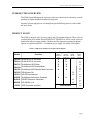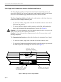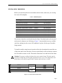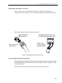
1
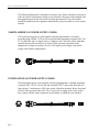
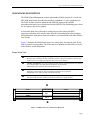
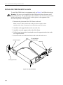
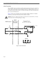
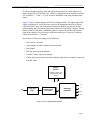
S5000 Signal Management System
and Power Supply User Guide
Doc# 14797
November 2004
14797 • November 2004 • Front Matter
SIGMA ELECTRONICS's products, including the S5000 and related components, are
certified to comply with the regulations and recommendations of several certifying
agencies.
For complete details, as well as copies of the certification documents, please visit our
website at www.sigmaelectronics.com or contact us using the Technical Support
contacts listed elsewhere in this document.
SYMBOLS
The presence of this symbol in or on SIGMA ELECTRONICS equipment means that it
has been designed, tested and certified as complying with applicable Underwriter's
Laboratory (USA) regulations and recommendations.
The presence of this symbol in or on SIGMA ELECTRONICS equipment means that it
has been designed, tested and certified as essentially complying with all applicable
European Union (CE) regulations and recommendations.
COPYRIGHT AND TRADEMARKS
Copyright © 2004, SIGMA ELECTRONICS, Inc. All rights reserved. Printed in USA.
SIGMA ELECTRONICS is a registered trademark of SIGMA ELECTRONICS, Inc.
DISCLAIMER OF LIABILITY
Contents of this publication are current as of the publication date. SIGMA ELECTRONICS reserves the right to
change the contents without prior notice. In no event shall SIGMA ELECTRONICS be liable for any damages
resulting from loss of data, loss of use, or loss of profits and SIGMA ELECTRONICS further disclaims any
and all liability for indirect, incidental, special, consequential or other similar damages. This disclaimer of
liability applies to all products, publications, and services during and after the warranty period.
SIGMA ELECTRONICS
P.O. Box 448
East Petersburg, PA 17520, USA
In USA and Canada: 1-866-569-2681
Outside USA and Canada: 717-569-2681
FAX: 717-569-4056
E-mail: [email protected]
Page ii
14797 • November 2004 • Front Matter
TECHNICAL SUPPORT
SIGMA ELECTRONICS has made every effort to ensure that the equipment you
receive is in perfect working order. In the event that problems arise which you cannot
resolve, or if there are any questions regarding this equipment or information about
other products manufactured by SIGMA ELECTRONICS, please contact your local
representative or contact SIGMA ELECTRONICS directly through one of the
appropriate means listed below:
Telephone:* Main Number - 1-717-569-2681*
Technical Support - 1-717-569-2681
Sales - 1-866-569-2681/1-717-569-2681
Facsimile:
Main Number - 1-717-569-4056
Sales - 1-717-569-4056
Mail:
Technical Support - [email protected]
Sales - [email protected]
Web Site:
http://www.sigmaelectronics.com
Mail:
SIGMA ELECTRONICS
P.O. Box 448
East Petersburg, PA 17520, USA
Shipping:*
SIGMA ELECTRONICS
1027 Commercial Avenue
East Petersburg, PA 17520, USA
* Return Authorization required before any equipment is returned.
Page iii
14797 • November 2004 • Front Matter
The following information is included for reference only. Please consult local electrical
codes for specific information relating to your situation. The power cords supplied with
this equipment provide the only means of mains disconnection. The socket-outlet
should be installed near the equipment and should be easily accessible as well as clearly
marked.
NORTH AMERICAN POWER SUPPLY CORDS
The North American power cords supplied with this equipment have a molded
grounding plug (NEMA 5-15P) at one end and molded grounding receptacle (IEC 320C13) at the other end (see figure below). Conductors are CEE color-coded: Light blue
(neutral), Brown (line) and Green or Green/Yellow (ground). Operation of this
equipment at voltages exceeding 130 VAC will require power supply cords which
comply with NEMA configurations.
INTERNATIONAL POWER SUPPLY CORDS
The International power cords supplied with this equipment have a molded grounding
receptacle (IEC 320-C13) at one end and a molded CEE7/7 plug at the other end (see
figure below). Conductors are CEE color-coded: Light blue (neutral), Brown (line) and
Green/Yellow (ground). Other IEC 320-C13 type power supply cords can be used if
they comply with the safety regulations of the country in which they are installed.
Page iv
14797 • November 2004 • Front Matter
TABLE OF CONTENTS
Introduction/Overview - - - - - - - - - - - - - - - - - - - - - - - - - - - - - - - - - - - - - - - - - - - - - - - - 1
Product Scope - - - - - - - - - - - - - - - - - - - - - - - - - - - - - - - - - - - - - - - - - - - - - - - - - - - - - - 1
Receiving Inspection and Unpacking - - - - - - - - - - - - - - - - - - - - - - - - - - - - - - - - - - - - - - 2
Backplane Configuration - - - - - - - - - - - - - - - - - - - - - - - - - - - - - - - - - - - - - - - - - - - - - - - 3
S5000 backplane options - - - - - - - - - - - - - - - - - - - - - - - - - - - - - - - - - - - - - - - - - - - - - 4
S5000 Frame Description - - - - - - - - - - - - - - - - - - - - - - - - - - - - - - - - - - - - - - - - - - - - - - 5
Frame Front View - - - - - - - - - - - - - - - - - - - - - - - - - - - - - - - - - - - - - - - - - - - - - - - - - 5
Frame Rear View - - - - - - - - - - - - - - - - - - - - - - - - - - - - - - - - - - - - - - - - - - - - - - - - - - 6
Frame I/O Backplane Descriptions - - - - - - - - - - - - - - - - - - - - - - - - - - - - - - - - - - - - - - 6
S5000 Frame Specifications - - - - - - - - - - - - - - - - - - - - - - - - - - - - - - - - - - - - - - - - - - - - - 7
Installing the Frame in a Rack - - - - - - - - - - - - - - - - - - - - - - - - - - - - - - - - - - - - - - - - - - - 8
Frame Door Installation and Removal - - - - - - - - - - - - - - - - - - - - - - - - - - - - - - - - - - - 9
Power Supply and Communication Interface Installation and Removal - - - - - - - - - - 10
Installing Modules - - - - - - - - - - - - - - - - - - - - - - - - - - - - - - - - - - - - - - - - - - - - - - - - - - 11
Making Connections to the Frame - - - - - - - - - - - - - - - - - - - - - - - - - - - - - - - - - - - - - - - 12
Signal Input and Output Connections - - - - - - - - - - - - - - - - - - - - - - - - - - - - - - - - - - 13
External Input and Output Terminations - - - - - - - - - - - - - - - - - - - - - - - - - - - - - - - - 13
Alarm Connections - - - - - - - - - - - - - - - - - - - - - - - - - - - - - - - - - - - - - - - - - - - - - - - - 14
Power Supply Module (PS5000) - - - - - - - - - - - - - - - - - - - - - - - - - - - - - - - - - - - - - - - - - 15
Power Supply Test Points - - - - - - - - - - - - - - - - - - - - - - - - - - - - - - - - - - - - - - - - - - - 16
Communications Interface Setup - - - - - - - - - - - - - - - - - - - - - - - - - - - - - - - - - - - - - - - - 17
S5000 System Theory of Operation - - - - - - - - - - - - - - - - - - - - - - - - - - - - - - - - - - - - - - 20
Maintenance - - - - - - - - - - - - - - - - - - - - - - - - - - - - - - - - - - - - - - - - - - - - - - - - - - - - - - - 22
Fuse Replacement - - - - - - - - - - - - - - - - - - - - - - - - - - - - - - - - - - - - - - - - - - - - - - - - - 22
Troubleshooting - - - - - - - - - - - - - - - - - - - - - - - - - - - - - - - - - - - - - - - - - - - - - - - - - - - - 23
Notes - - - - - - - - - - - - - - - - - - - - - - - - - - - - - - - - - - - - - - - - - - - - - - - - - - - - - - - - - - - - 24
Page v
14797 • November 2004 • Front Matter
Page vi
14797 • November 2004 • Introduction/Overview
INTRODUCTION/OVERVIEW
The S5000 Signal Management System provides an economical yet extremely versatile
platform for signal distribution and processing tasks.
Separate left and right passive rear backplanes permit differing tasks to reside within
the same frame.
PRODUCT SCOPE
The S5000 is shipped with (1) power supply and (2) backplane adapters. Three styles of
rear backplane are available From SIGMA ELECTRONICS as well as a wide variety of
distribution and processing modules. Modules and the appropriate mating backplane
options are summarized below. A redundant power supply is available as an option.
Table 1. S5000 Series Modules and Supported Backplanes
Supported Backplanes
Module
Function
DA5305 Quad AES A-D Converter
DA5310 Quad AES D-A Converter
DA5315 OctaStream AES Delay
DA5320 OctaStream AES Router/Mixer
DA5325 OctaStream AES Sample Rate Converter
DV5505 SDI Monitor DA
DV5515 HD-SD Synchronizer
SG5605 OctaStream Reference Generator
SG5610 HD/SD Reference Generator
HD5805 HD-SDI DA 1x 8
CI5705 5000 Controller Interface
RP302
Twisted Pair
AES
RP303
BNC AES
Analog Video
X
X
X
X
X
X
X
X
X
X
RP305
HD-SDI
SD-SDI
X
X
X
X
X
X
None Needed
NVision
IO594
Optical
C
O
N
T
A
C
T
N
V
I
S
I
O
N
Page 1
14797 • November 2004 • Receiving Inspection and Unpacking
RECEIVING INSPECTION AND UNPACKING
By the time you have found and opened this manual, you have already begun to unpack
the shipping container. Since damage may have occurred in shipping it is important to
perform the following checks immediately:
• Inspect the shipping container(s) for damage.
• If you find any damage to the containers, carefully inspect the product for damage.
• If any damage is discovered, notify the shipping carrier immediately.
Compare what you received against the packing slip. If anything is missing or has
suffered damage unrelated to shipping, contact SIGMA ELECTRONICS Technical
Support immediately. Contact information is located at the front of this manual.
Page 2
14797 • November 2004 • Backplane Configuration
BACKPLANE CONFIGURATION
The S5000 can be easily reconfigured in the field if requirements change. Typically the
rear backplanes need to be replaced to accommodate a different module loading. If you
obtained the S5000 with no rear backplanes installed, or simply need to replace one
refer to the steps and figure below.
1. Remove AC power connection(s) to the frame by disconnecting the line cord(s).
2. Disconnect all cables from the frame and remove the frame from the rack. DO
NOT attempt to change backplanes with the frame installed!
3. Remove all modules from the affected side of the frame.
4. Remove the screws holding the backplane in place.
5. Gently pull the backplane assembly rearward and out of the frame.
6. Install the replacement backplane being careful not to damage the copper EMI
gasket or motherboard I/O pins. It helps to line up the I/O pin side of the backplane
first.
7. Install modules, reconnect cabling and apply AC power.
Figure 1. Removing the I/O Backplane
Page 3
14797 • November 2004 • Backplane Configuration
S5000 backplane options
SD/HD-SDI
EM0305-00
RP305 SWB I/O
AES
EM0303-00
RP303 BNC I/O
AES
EM0302-00
RP302 Twisted Pair I/O
Figure 2. S5000 backplanes
Page 4
14797 • November 2004 • S5000 Frame Description
S5000 FRAME DESCRIPTION
The S5000 Signal Management System (part number S5000) consists of a 2 rack unit
(RU) high metal frame assembly that installs in a standard 19” wide equipment rack.
The frame includes a built-in motherboard (EM0328) that provides module
interconnections and a power distribution board (EM0326) for distributing power from
the AC inputs to the power supplies.
A removable front door with built-in cooling fan provides cooling and EMI
suppression. Modules slide into the frame from the front and plug into the backplane
and motherboard. Information about the modules is presented in the individual module
User Guides.
Figure 3 illustrates the S5000 Frame front view (door open), showing the slots for the
slide-in printed circuit modules. The following list of printed circuit modules is keyed
to the numbers on the illustration:
Frame Front View
Œ
PS5000 Power Supplies: Two power supply modules slide into the center of the frame from
the front. One is standard, the other redundant (optional). The power supplies accept 90-130/
180-250 VAC (auto-ranging) and produce DC power for all modules.
•
Left Bay of 5 Modules: Any of the available modules may be inserted into these slots, depending on the backplane. Note that different backplanes are required for
SDI/HD-SDI video, balanced AES and unbalanced AES.
Ž
Right Bay of 5 Modules: Any of the available modules may be inserted into these slots,
depending on the backplane. Note that different backplanes are required for
SDI/HD-SDI video, balanced AES and unbalanced AES.
•
CI5705 Communication Interface: The module that provides communication between modules in the frame and other frames is located above the power supply modules.
•
Card 1
Card 2
Card 3
Card 4
Card 5
•
Comm Intrfc
PS 1
PS 2
Card 6
Card 7
Card 8
Card 9
Card 10
Œ
Ž
Figure 3. S5000 Front View with the Door Removed
Page 5
14797 • November 2004 • S5000 Frame Description
Frame Rear View
Figure 4 illustrates the S5000 Frame rear view. The following list, which is keyed to the
figure, explains the purpose of the connectors on the rear panel.
Œ
Video Reference Inputs: Analog NTSC or PAL looping 75 ohm reference video input. Not
used with DA modules.
•
IEC Standard AC power connectors: Connect to AC power.
Ž
Alarms Connector: Open collector type power supply alarm outputs. May be connected to a
customer-supplied alarm indicator.
•
Network Connector: RS-485 9-pin D connector. Commands and queries to the CI5705 Communication Interface are made through this connector.
•
Input/Output Connectors: Connect inputs and outputs to the modules using these connectors.
Connectors are mounted in rows directly behind the modules they serve. For example, the top
row of connectors corresponds to the top module.
A
B
C
D
E
F
G
H
I
J
A
B
C
D
E
F
G
H
I
J
EM0305-00
Œ
•
•
P/S 1
CAUTION
VIDEO REF
A
B
C
D
E
F
G
H
I
J
A
B
C
D
E
F
G
H
I
J
A
B
C
D
E
F
G
H
I
J
A
B
C
D
E
F
G
H
I
J
A
B
C
D
E
F
G
H
I
J
EM0305-00
•
B
C
D
E
F
G
H
I
J
A
B
C
D
E
F
G
H
I
J
A
B
C
D
E
F
G
H
I
J
ON POWER SUPPLIES
P/S 2
ALARMS
SIGMA ELECTRONICS, INC.
5000 SERIES
90-130/180-250V~
1.2A/0.6A
50/60Hz
105 WATTS MAX
Ž
R
CONTROL NO. 9K50
PROFESSIONAL
VIDEO/AUDIO
SD/HD-SDI
A
SD/HD-SDI
T 1.25A 250V FUSES LOCATED
NTWK EIA-485
•
Figure 4. S5000 Rear Panel
Frame I/O Backplane Descriptions
Three I/O backplanes are currently available for the S5000 frame. All three backplanes
are completely passive and contain no active circuitry:
• SDI/HD-SDI Digital Video I/O (RP305)—Accepts SDI or HD-SDI modules.
Contains high quality, high data rate BNC connectors.
• AES Unbalanced I/O (RP303)—Accepts AES digital audio and analog video
modules. Uses standard BNC connectors for single-ended connections.
• AES Balanced I/O (RP302)—Accepts AES digital audio modules. Uses Phoenix
terminal block connectors for balanced connections.
The backplanes install independently on the back of the frame. The same backplane can
be used on both sides, or you can mix backplanes on the same frame.
Page 6
14797 • November 2004 • S5000 Frame Specifications
S5000 FRAME SPECIFICATIONS
Table 2 lists specifications for the S5000 Signal Management System.
Table 2. S5000 Frame Specifications
Type
Electrical
AC Power
AC Fuses
AC Connectors
Power Consumption
Regulatory Compliance
Mechanical
Module Slots
Power Supply Slots
Dimensions
Weight (fully loaded)
Video Ref Input
Type
Connectors
Return Loss
External Communications Port
Type
Connectors
External Alarm Port
Environmental
Operating Temperature
Relative Humidity
Parameter
90-130/180-250 VAC, 50/60Hz, Auto-ranging
1.25T - 1.25A, 250V SloBlo, 5 x 20 mm
2, IEC Filtered AC
105 Watts (maximum)
UL Listed and CE Compliant
10
2 (1 Main, 1 Optional Redundant)
EIA Standard
2 RU (3.5 inches, 89 mm) High
19.0 inches (482.6 mm) Wide
15.0 inches (381 mm) Deep
25 lbs (11.35 kg) maximum.
Analog PAL and/or NTSC Color Black (not required for DAs)
BNC with loop-thru
>30dB to 5MHz
EIA-485 (reserved for future use)
1 9-pin D
1 3-pin Phoenix
0 to 40 degrees Centigrade, ambient
0 to 90%, non-condensing
Page 7
14797 • November 2004 • Installing the Frame in a Rack
INSTALLING THE FRAME IN A RACK
To install the S5000 frame in an equipment rack, see Figure 5 and follow these steps:
Warning: The power cords supplied with the S5000 provide the only means of AC
mains disconnection. The equipment must be located near the AC source power outlet
and the outlet must be easily accessible to allow power to the equipment to be
disconnected quickly in an emergency.
1. Determine the placement of the 2 RU frame in the rack.
Note: Be sure to allow unrestricted cooling air flow through the front
and sides of the frame. Frames may be stacked with no space in between.
2. Attach the rack support brackets to the rear rack rails.
3. Attach the rear rack supports to the sides of the frame.
4. Lift the frame into position, inserting the rear rack supports into the slots in the
rack support brackets.
5. Secure the rack ears at the front frame to the rack with rack screws.
Rear Rack Supports
Do not block air
vents at sides
Rack Ears
Co
olin
gA
irflo
w
Rack Support Bracket
Figure 5. Frame Installation
Page 8
14797 • November 2004 • Installing the Frame in a Rack
Frame Door Installation and Removal
The frame door includes latches on both sides that must be pressed inward in order to
remove the door.
Caution: Be careful not to drop and damage the door when you release the latches. The
latches are the only mechanism holding the door in place.
When installing the door, just push the door onto the frame and the latches will latch
themselves automatically.
Push latch
toward fan
to open
Push latch
toward fan
to open
Figure 5-1. Removing the Frame Door
Page 9
14797 • November 2004 • Installing the Frame in a Rack
Power Supply and Communication Interface Installation and Removal
The Power Supply modules and Communication Interface install in the slots in the
center of the frame. If you have only one power supply module, install it in the bottom
center slot. The redundant supply installs directly above the main module.
The Power Supply module has a latch similar to the latches on the frame front cover
to ensure the Power Supply remains in place.
• To insert the module, simply slide it into the cell until the connector seats and the
latch snaps into position.
• To remove the Power Supply module, grasp the card pull tab while pushing the
latch to the left and pull the card straight out of its slot. (See Figure 6.)
Caution: (1) To prevent damage to the Power Supply module latch, be sure to press the
latch open (to the left) when removing the module.
Caution: (2) Heat sinks and other components may be hot. To prevent burns, avoid
touching components.
The Communication Interface installs in the slot above the redundant Power Supply.
• To insert the module, simply slide it into the cell until the connector seats.
• To remove the Communication Interface module, grasp the extractor, pivot toward
the front and pull the card straight out of its slot. (See Figure 6.)
C I5705 - Pivot
extractor toward
front, then pull card .
C A R D P U L L - Pull
toward you while
releasing latch.
LATCH - Push left
to release module.
Figure 6. Removing the Power Supply Module
Page 10
14797 • November 2004 • Installing Modules
INSTALLING MODULES
Before you insert the printed circuit modules into the frame, make sure you are using
the correct I/O backplane.
Table 3. S5000 Backplanes
Module Type
Model Number
Required I/O Backplane
Quad AES A-D Converter
DA5305
AES backplane
Quad AES D-A Converter
DA5310
AES backplane
OctaStream AES Delay
DA5315
AES backplane
OctaStream Router/Mixer
DA5320
AES backplane
OctaStream Sample Rate Converter
DA5325
AES backplane
OctaStream Ref Generator
SG5605
AES backplane
SDI Monitor DA
DV5505
SWB backplane
HD-SDI Synchronizer
DV5515
SWB backplane
HD-SDI Ref Generator
SG5610
SWB backplane
HD-SDI DA 1x8
HD5805
SWB backplane
You can now insert the circuit boards into the frame. Note that boards can be inserted
and removed with power on. Referring to Figure 7, insert modules into any available
card slots, making sure the correct I/O backplane is in place for the type of modules
being inserted.
To install a module, simply insert it into the rails in the slot and push it toward the rear
of the frame until it seats into place. Be sure to push firmly on the card when it contacts
the I/O module to ensure it seats. Then make connections to it at the back of the frame.
Caution: For proper cooling, the frame door must remain closed. The door may be
opened for a short time, but irregular performance may occur. The temperature and
performance will stabilize again within 5 minutes after the door is closed.
Card 1
Card 2
Card 3
Card 4
Card 5
Comm Intrfc
PS 1
PS 2
Card 6
Card 7
Card 8
Card 9
Card 10
Figure 7. Card Locations in the Frame
Page 11
14797 • November 2004 • Making Connections to the Frame
MAKING CONNECTIONS TO THE FRAME
B
C
D
E
F
G
H
I
J
A
B
C
D
E
F
G
H
I
J
P/S 1
CAUTION
A
B
C
D
E
F
G
H
I
J
A
B
C
D
E
F
G
H
I
J
A
B
C
D
E
F
G
H
I
J
A
B
C
D
E
F
G
H
I
J
A
B
C
D
E
F
G
H
I
J
VIDEO REF
EM0305-00
A
EM0305-00
Make connections to the frame as described on the following pages. For the specific
inputs and outputs of a particular module, please refer to the individual user guide for
that module. The frame backplane (BNC) is shown in Figure 8 below.
B
C
D
E
F
G
H
I
J
A
B
C
D
E
F
G
H
I
J
A
B
C
D
E
F
G
H
I
J
ON POWER SUPPLIES
P/S 2
ALARMS
SIGMA ELECTRONICS, INC.
5000 SERIES
90-130/180-250V~
1.2A/0.6A
50/60Hz
105 WATTS MAX
R
CONTROL NO. 9K50
PROFESSIONAL
VIDEO/AUDIO
Figure 8. S5000 Frame I/O Backplane (RP305 SWB I/O)
Page 12
SD/HD-SDI
A
SD/HD-SDI
T 1.25A 250V FUSES LOCATED
NTWK EIA-485
14797 • November 2004 • Making Connections to the Frame
Signal Input and Output Connections
Make connections to the AES audio, SDI video, or HD-SDI video signal input
connectors as shown in Figure 9. Use 75 ohm cable for BNC connectors or 110 ohm
shielded twisted pair cable for Phoenix connectors.
AES or SDI/HD-SDI
BNC connection
AES Balanced Audio Connection
Using Shielded Twisted Pair Cable
+ - S
Phoenix - Use
110 ohm shielded
twisted pair cable
BNC - Use 75 ohm
coaxial cable
Figure 9. Typical Input and Output Connections
External Input and Output Terminations
Unused inputs of SDI modules and both the unused inputs and unused outputs of Super
Wideband HD-SDI modules should be terminated using a customer-supplied 75-ohm
external termination.
SDI outputs and AES inputs and outputs do not need to be terminated.
Page 13
14797 • November 2004 • Making Connections to the Frame
Alarm Connections
The ALARMS connector includes normally closed connections from pin 1 and pin 2 to
COM, which is connected to chassis ground. If both Power Supply modules fail (or AC
is disconnected from both), the pin 1 to COM circuit opens. The alarm associated with
pin 2 is reserved for future use.
Figure 10 shows one circuit that can be used with the Alarms connector. It contains
LEDs that are normally OFF and turn ON to indicate a failure.
Caution: The power supply for the alarm circuit must not exceed 30 VDC or 150 mA.
Load resistor value varies depending on voltage.
S5000 Internal
S5000
Rear Alarm
Connector
Example Circuit
LEDs switch ON to indicate fault
NC
1
22k
P/S fail
470
LED1
470
LED2
1k
Q1
COM
22k
2
NC
1k
see text
Q2
Alarms
1
C OM
Figure 10. Alarm Connections
Page 14
2
+
_ 9 - 18 VDC
14797 • November 2004 • Power Supply Module (PS5000)
POWER SUPPLY MODULE (PS5000)
The Power Supply module accepts and adjusts automatically to a wide range of AC
input voltages (90-130/180-250 VAC, 50/60 Hz). Regulators on the module rectify the
AC to produce +/- 7 and +/- 15 VDC which is distributed to the other modules in the
frame.
Figure 11 shows a block diagram of the Power Supply module. The input stage of the
supply includes an AC power line fuse to protect the equipment and a Power Factor
Correction (PFC) stage, which minimizes harmonics and peak currents on the line.
Following this stage a Switching Regulator produces the required DC voltages. Sharing
diodes on the DC rails allow redundant supplies to connect in parallel with isolation
between the supplies. Power for the cooling fan and the green “power on” indicator
LED comes from the +15 volt rail.
Key features of the power supply are the following:
• Power factor correction
• Auto-ranging; no input voltage selection required
• Fused input
• LED DC power present indicator
• Current, voltage, and power limiting
• Charge dump circuit drains hazardous voltages when the power supply is removed
from the frame.
Control
Circuits
Voltage, current, and
power sensing and
limiting
+7
AC
Fuse and
Filter
Power Factor
Correction
Switching
Regulator
-7
+15
-15
Figure 11. Power Supply Block Diagram
Page 15
14797 • November 2004 • Power Supply Module (PS5000)
Power Supply Test Points
There are four test points on the front edge of the power supply modules. When
checking the test points, test both the main and redundant supplies. The approximate
range of voltages that may be expected at these points is listed below. Voltages outside
of listed ranges may indicate a bad power supply module; replace with a known good
module.
Table 4. Power Supply Test Points
PS TEST POINT
+7
-7
+15
-15
DC VOLTAGE RANGE
+6.0 to +8.0
-6.0 to -8.0
+13.0 to +16.0
-13.0 to -16.0
Warning: Power supply components may be hot when the power supply has been
operating. To prevent burns, do not touch components when removing power supplies.
Page 16
14797 • November 2004 • Communications Interface Setup
COMMUNICATIONS INTERFACE SETUP
The CI5705 can be used to control operation of modules within the S5000 frame. This
is accomplished via communications through a 9-pin D-subminiature connector located
on the back of the unit labeled NTWK EIA-485. Communications to the S5000 must
adhere to the RS-485 or RS-422 communications protocol.
The NTWK EIA-485 connector on the rear of the S5000 utilizes the pinout detailed in
the table which follows.
Table 5. NTWK EIA-485 Pin Assignment
PIN #
FUNCTION
DIRECTION
1
Ground
---
2
Receive A
Output- Rx Data (A)-
3
Transmit B
Input- TxData (B)+
4
Receive Common
---
5
N/C
---
6
Ground
---
7
Receive B
Output- Rx Data (B)+
8
Transmit A
Input- Tx Data (A)-
9
Ground
---
Computers equipped with only RS-232 communications ports will require an RS-232to-RS-422/485 converter like the B&B Electronics model #4WSD9R (http://www.bbelec.com/bb-elec/literature/4WSD9R-3903ds.pdf for more information), or others, to
successfully communicate with the S5000 frame. Carefully check the pinout of the
device you select. If it does not match the above information, an adapter cable may need
to be made.
The CI5705 communications interface needs to have a number of parameters
configured for proper operation when connected to a master controlling device via the
NTWK EIA-485 connector on the rear of the S5000.
Each frame in the system must have its own identity. The identification code is assigned
to the frame using the first three DIP switches (SW1,SW2 and SW3) of S2 located at
the front of the CI5705 card. The following table indicates the settings required for each
Frame ID.
Page 17
14797 • November 2004 • Communications Interface Setup
Table 6. Frame ID Setting
FRAME ID
SW1
SW2
0
SW3
RESERVED
1
OFF
ON
ON
2
ON
OFF
ON
3
OFF
OFF
ON
4
ON
ON
OFF
5
OFF
ON
OFF
6
ON
OFF
OFF
7
OFF
OFF
OFF
Depending upon the controlling device’s operating parameters, the CI5705 may need to
have its communication speed changed. DIP switches SW4 and SW5 of S2 located at
the front of the CI5705 card are used to set the communication speed as detailed in
Table 6 belowTable 7. Communication Speed
Page 18
SPEED
SW4
SW5
9600
ON
ON
19.2K
OFF
ON
38.4K
ON
OFF
57.6K
OFF
OFF
14797 • November 2004 • Communications Interface Setup
Page 19
14797 • November 2004 • S5000 System Theory of Operation
S5000 SYSTEM THEORY OF OPERATION
See Figure 12. The S5000 frame is a relatively simple system consisting of a metal rack
frame, replaceable I/O backplanes on each side of the back of the frame, a power
distribution board, and a motherboard. A variety of modules may be inserted into the
frame as desired to create a complete signal distribution and processing system.
The I/O backplanes hold the BNC or Phoenix I/O connectors to which the external
input/output cables are connected. The plug-in DA modules are fitted with connectors
that plug into the backplane BNC or Phoenix connectors to carry I/O signals onto and
off of the modules.
A rear motherboard (EM0328) inside the center rear of the frame connects to the I/O
modules and, in the case of video cards, connects directly to processing modules via
connectors at the corner of each module cell. Reference signals, DC power, and other
signals are carried between modules via the motherboard.
A Power Distribution board (EM0326) inside the center rear of the frame connects the
external AC power connectors to the Power Supply modules.
Page 20
14797 • November 2004 • S5000 System Theory of Operation
Motherboard Assembly
Power Distribution Board
Card Corner Connectors
Connect Here
AC Connectors
Figure 12. S5000 Frame Exploded View
Page 21
14797 • November 2004 • Maintenance
MAINTENANCE
The S5000 does not require any periodic electrical or physical maintenance. You may
want to check the system’s indicators occasionally to ensure that the system is operating
normally and to make sure cooling air flow through the fan in the front of the frame is
unobstructed.
Fuse Replacement
Fuses are located on Power Supply modules. If a problem occurs on a module, the first
thing to do is check the fuses. The following table lists the fuses:
Table 8. Power Supply Fuses
LOCATION
Power Supply AC Line Fuse
FUSE VALUE
5 x 20 MM Time-Delay 1.25A
Warning: Dangerous voltages and high temperatures are present on the Power Supply
Card. Take precautions to prevent burns and electric shock: Do not touch exposed
wires, connecting pins, heat sinks, or components. Handle the board by its edges.
Page 22
14797 • November 2004 • Troubleshooting
TROUBLESHOOTING
Many system troubles are caused by easily-corrected errors, such as poor quality or
missing input or reference signals. Table 9 lists common problems and their solutions in
approximately the most likely order of occurrence. Try troubleshooting the system
yourself, and if you are not successful, call Sigma Electronics Technical Support, as
explained near the front of this manual.
In the event that a problem is caused by a bad circuit board, swapping the bad board
with a replacement circuit board is the quickest solution. If you need to order
replacement boards or other assemblies, call Sigma Electronics Technical Support.
Table 9. System Troubleshooting
SYMPTOM
System not powering up.
POSSIBLE CAUSES AND SOLUTIONS
Verify that the power cord(s) are plugged into the frame and the AC power
source. Use a voltmeter to verify the presence of power at the AC mains.
Check the DC test points on the front of the Power Supply modules (see Power
Supply Test Points on page 16.)
Check the AC line fuse on the Power Supply module. See Fuse Replacement on
page 22.
One or a few modules not powering Check that the modules are fully seated in the frame.
up or not operating properly.
Intermittent or missing signal on
Check input sources to make sure the signal is in good condition at the point
outputs.
where it originates.
Check input and output cable continuity while wiggling the cables.
Possible low voltage on Power Supply module. Check Power supply test point
voltages. See Power Supply Test Points on page 16.
Possible bad DA/Processing module. Swap the module with a known good
module.
Page 23
14797 • November 2004 • Notes
NOTES
Page 24