1
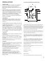
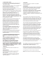
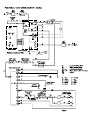
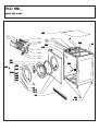
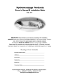
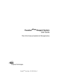
&$)
INSTALLATION AND SERVICE INSTRUCTIONS
Keep this booklet for future reference.
The dryer must be fitted by a competent person. In the U.K. Registered Installers undertake to
work to safe and satisfactory standards.
The dryer must be installed in accordance with the Gas Safety (Installation and Use)
Regulations 2009.
Guidance may be obtained from the relevant parts of B.S. 7624: B.S. 5440 parts 1 and 2, B.S.
6891: current editions, I.E.E. Wiring Regulations, and relevant Building Regulations.
Failure to install the appliance correctly could invalidate the warranty liability claims and could
lead to prosecution.
FOR USE IN THE UNITED KINGDOM AND IRELAND WITH
NATURAL GAS ONLY I2H, GAS SUPPLY PRESSURE : 20 mbar.
THE INSTALLER MUST LEAVE THIS BOOKLET WITH THE
CUSTOMER
Contents
Technical Data
Installation
Service instructions
Wiring diagram
Exploded views
Parts list
WARNING
THIS APPLIANCE SHALL BE
INSTALLED IN ACCORDANCE WITH
THE LOCAL REGULATIONS IN
FORCE AND ONLY IN A WELL
VENTILATED SPACE.READ THE
INSTRUCTIONS BEFORE USING
OR
INSTALLING THIS APPLIANCE.
THIS APPLIANCE CONFORMS TO THE FOLLOWING EEC DIRECTIVES.
LOW VOLTAGE DIRECTIVE LVD 2006/95/EC:EN60335-1, EN60335-2.11.
GAS APPLIANCE DIRECTIVE (GAS) GAD 2009 142 EC, BS EN 1458-1
EN 1458-1, 2000 ELECTROMAGNETIC COMPATIBILITY DIRECTIVE 2004/108/
EC:EN55014, EN 61000 - 3 - 2, EN 61000 - 3 - 3, EN 62233
2
TECHNICAL DATA
CONTROL
GENERAL
Type:Pactrol full sequence flame control, P16AGTD(CE)
414601. Ignition electrode gap to burner 3 to 4mm Flame
failure electrode (4213 078 52641).Height from heater
base to centre of electrode 27.0±0.5mm.
Front loading resistance sensing tumble dryer with gas
heating.Reverse action drum tumble.Electronic control.
2-temperature exhaust thermostat control.Induced air flow
enters dryer through front grille, some passes through the
gas burner into the rear ducting and some into the cooling
passages, this mixed air enters the drum through the rear
perforations, passes through the clothes, lint filter, and
the fan and is discharged through the vent at the rear.
CONNECTIONS
Gas pressure:Rp 1/2 (1/2”B.S.P.parallel internal thread).
Nominally 20mbar
Electric: 230V.50 Hz, earthed supply, 13A fuse.
(wall socket must have efficient earth connection and
correct polarity)
DIMENSIONS
Height 85 cms.(33 1/2”)
Width 59.6 cms.(23 5/8”)
Depth 57 cms.(22 1/2”)
Depth when rear vent hose assembled 60cms.(23 5/8”)
WEIGHT
With packing 37 kg
Without packing 36 kg
SUPPORT
Machine rests on 2 rear positioned rollers and 2 non
adjustable feet.
AIR-FLOW
Approximately 120 cubic metres per hour with capacity
clothes load.
IDENTITY
Manufacture date, and serial number are displayed on a
plate revealed when machine door is open.
The first 4 numerals identify year and week of
manufacture.
The last 6 numerals identify the machine.ALL
INFORMATION FROM THIS PLATE SHOULD BE
QUOTED IN ANY SERVICE COMMUNICATION.
COMPONENTS
DRIVE MOTOR
Permanent split capacitor (8µF)4 pole—Approx. 1/8 HP
Overload protection approx.130˚C
BURNER
Pressed steel with slotted flame perforations.
Heat input:3.0kW (10235 Btu/hr).Injector 1.32 mm dia.
3
INLET THERMOSTAT
(Brown wires identification)
Bi-metal contacts normally closed.
Contacts open if airflow restricted.
Contacts open 130˚C ±3˚C
Contacts reset 100˚C ±5˚C
INLET TEMPERATURE LIMITER
(White wires identification)
Bi-metal contacts normally closed.
Contacts open if INLET THERMOSTATfails.
Contacts open 143˚C ±3˚C
Contacts reset 100˚C ±5˚C
EXHAUST THERMOSTATS
Bi-metal contacts normally closed.
Normal Fabrics:Contacts open 60˚C ±3˚C
60˚C (green spot Contacts reset 49˚C ±4˚C
identification)
Delicate Fabrics:Contacts open 50˚C ±3˚C
50˚C (red spot Contacts reset 35˚C ±3˚C
identification)
DRUM
Volume 105 litres
Speed approx.50/59 r.p.m.
Capacity 7 kg dry cotton
Rotation clockwise 5 mins., anticlockwise 10 secs
TRANSMISSION
Poly-vee belt driven by vee-grooved motor pulley to outer
circumference of drum.
ELECTRONIC CONTROL
9 selectable programmes giving choice of dryness level
and timed programmes.When drying is complete,
intermittent tumbling (anticrease, if selected) follows until
the machine is unloaded.
SELECTOR
Choice of Heat, Full Heat, Half Heat or Cool
ACTIVATE SWITCH-momentary push switch.
R.F.I.FILTER
0.1µF +2x2400pF +2x5mH +2M2
ACCESSORIES
VENT HOSE ASSEMBLY0312 001 01001
WALL/WINDOW VENT KIT0312 005 01001
STACKING KIT0312 003 01001
RESTRAINING KIT0312 006 01001
INSTALLATION
5 POSITION OF DRYER AND CONNECTIONS
1INSTALLATION
The dryer is designed for installation using a flexible gas
connection with tubing in accordance with B.S.669.
Ensure that the supply gas sizing is adequate.
When installing, position the appliance so that the plug is
accessible.
An electric supply cord with moulded-on 13 Amp.plug is
fitted at the back of the dryer.The length is 1.5 m.(5ft.).
If there are any other appliances that are relatively high
rated (eg a central heating boiler)fed from the same gas
supply branch, it is advisable to perform the verification of
inlet pressure with both appliances in operation.
Prior to installation, check that the local distribution
conditions, nature of gas and pressure and adjustment of
the dryer are compatible.
2 AIR SUPPLY
The tumble dryer shall be installed in a room or internal
space having an openable window, or equivalent.The
customer must be advised that this must be kept open
during use.
Purpose provided ventilation of 100cm² shall also be
provided where the room volume is less than 3.7m 3/kw
of appliance rated heat input.
Additional guidance on the provision of air supply may be
obtained from BS5440 parts 1 and 2 and BS 7624:2004
If the dryer is to be installed in a room or internal space
that already contains one or more fuel burning
appliances, the ventilation requirements above, together
with any additional requirements of BS5440-2:2009, 5,5
shall be applied.
3 POSITION
The dryer must not be installed in a bedroom, bathroom
or shower room.
Great care is required in the location of the dryer in
premises where concentrations of flammable vapours
may accumulate, e.g.commercial garages and associated
workshops.
The dryer can be placed against a wall, other appliances,
kitchen furniture and similar surfaces.
4 VENTING
The dryer must be fitted with an exhaust vent hose and
the end either hung out of a window or fitted to a wall/
window vent connection.
Note: Do not obstruct or add a mesh to the vent hose
outlet during use and ensure that it cannot be blocked or
bent sharply which obstructs the air flow.
It is recommended that the interior of the hose be
periodically inspected and cleaned if necessary.
PERMANENT VENTING
Accessory wall/window vent kit CL005 is available:
See illustration for necessary hole through wall.Dim A=
200mm and Dim B= 100mm for direct alignment.
Note DimBmay be increased to 200mm to facilitate easier
drilling if required.
The illustration shows the minimum space required by the
dryer and the position of the gas wall connector.It is not
acceptable to use a forward facing mounting plate because
of the space limitation.The sideways facing assembly must
be used and this should be fitted so that the flexible hose
hangs down from the bayonet connector.
A 13 Amp socket must be provided within a distance of 1.4
m (55 in.) of the cable entry into the dryer.The socket must
have an efficient earth connection.
If the dryer is to stand on a surface above the floor or on
top of a washing machine (using the Stacking Kit) then the
750 mm dimension is measured above the supporting
surface.
If the dryer is installed under a worktop there must be a
minimum gap of 15 mm between the top of the dryer and
the underside of the worktop to allow for ventilation.
If it is intended to move the dryer regularly for use then the
Restraining Kit must be fitted to prevent possible damage
to the gas connection.
We also recommend the fitting of a restraining kit to any
dryer which is stacked.
If using accessories:
Wall/Window Vent Kit
Stacking Kit
Restraining Kit
See separate fitting instructions included with each Kit.
4
6. OPERATIONAL CHECK
6.1 Remove the pressure test point screw from the gas
tee connection at the back of the dryer and connect
a gas pressure gauge.
6.2 Check that the dryer control is in the 'off' position, and
that the heat switch is set to 'high'.
Remove anything from inside the drum, check that
the lint filter is fitted, shut the dryer door.
6.3 Turn on the gas, push the electric plug into the socket
and switch on the electricity supply.
6.4 Select program 9 (Timed). Check for ignition.If the gas
fails to remain lit then repeatedly open and close the
door, push the start switch and run the machine for
periods of at least 30 seconds until the air is
removed from the system and burning is continuous.
Note that gas is not lit when the drum is turning anticlockwise. The flame recognition system will only
operate if the electric supply is polarity correct - live
is live and neutral is neutral.
6.5 With the gas burning ensure that the pressure is as
detailed in the Technical Data.Turn off and replace
the pressure test point screw.Check for soundness.
6.6 Switch on again and re-start so that the gas is
burning.Disconnect the flexible gas hose and check
that the solenoids can be heard to close.After 30
seconds turn on the gas and check that there is no
re-ignition.Switch the machine off and on again and
check for re-ignition.
6.7 Check that the operation of the machine does not
cause spillage of products of combustion from any
open flued gas appliance in the same room, or from
appliances in adjoining rooms, e.g.a gas fire or
central heating boiler.
6.8 In the event of an electrical fault after installation of
the appliance, preliminary electrical system checks
must be carried out (i.e.earth continuity, polarity and
resistance to earth).
6.9 IMPORTANT INFORMATION RE-FUNCTIONING
OF THE FULL SEQUENCE FLAME CONTROL
BOX.
THE FULL SEQUENCE FLAME CONTROL BOX
ON THIS APPLIANCE REQUIRES A 6-12 SECOND
RE-SET PERIOD FOLLOWING EACH
INTERRUPTION OF INPUT VOLTAGE.
6 SECONDS DELAY IS REQUIRED BETWEEN
EACH ATTEMPT TO RESTART THE APPLIANCE
FOLLOWING SWITCHING IT OFF, OR AFTER
OPENING THE DOOR. THE CONTROL BOX WILL ONLY
WORK CORRECTLY WHEN THE ELECTRIC SUPPLY
TO THE DRYER HAS CORRECT POLARITY - LIVE IS
LIVE AND NEUTRAL IS NEUTRAL
9 STACKING
Instructions for stacking, if required, are supplied
with the stacking kit.
PROGRAMME
The electronic control measures dryness by the electrical
resistance method and operates relays to:a) energise
the drive motor, in foward and reverse rotation and b)
energise the full sequence flame controller.
The electronic controller determines when the selected
dryness level is reached, then turns off the heat source
and continues to rotate the drum for 12 minutes
"cool down", intermittent tumbling follows this until the
machine is unloaded - "anticrease" is indicated by an LED
(if selected).
The full sequence flame controller opens the tandem
solenoid gas valves after a delay time of about 8 seconds
and operates the pulsing spark ignition.If the flame is not
detected by the flame failure electrode within 10 seconds
then the valves are closed.The system must then be reset by switching the machine off and re-starting.
The heat selector switch provides options for either 60˚C,
or 50˚C, exhaust thermostat control.This results in the
burner cycling on and off giving Ionger than anticipated
drying times.Drying times vary depending on the weight
and size of the articles, type of fabric, dampness etc.
These thermostats turn off the heating towards the end of
the chosen cycle and so avoid waste of energy.The lower
temperature thermostat prevents delicate fabrics from
getting too hot with possible risk of damage.
An inlet thermostat is fitted in the ducting at the back of
the dryer.It may also operate under certain other
conditions of restriction of the air-flow, for example, an
overloaded drum or blocked lint filter.This thermostat
switches off the flame controller.This will result in the
burner cycling on and off giving longer than anticipated
drying times.
Should the thermostat fail there is an inlet cut-out
connected in circuit with the gas valves.After operation,
the cut-out can be re-set by switching OFF/ON the
mains supply for a periood, to restore heating but a service
call may be required to correct the initial fault.
The conditions of failure of the air flow, blow-back, or of
gas interruption are detected by the flame failure
electrode and the system is shut-down.
7 AIRFLOW
It is most important that airflow to the plinth is not
restricted.
Both drum rotation and heater control are switched off
when the door is opened and switched on when the door
is reclosed, and the activate and start buttons pressed.
8 MAINTENANCE
This appliance does not require an annual service
unless it is required as part of a landlord's gas
safety certificate.
If you do have any maintenance activity carried out,
it should be carried out by a competent person (i.e.
registered Engineer).
For programmes see chart on dryer control panel.
Note:Do not allow fluff to accumulate around the dryer.
5
SERVICE INSTRUCTIONS
RECOMMENDATIONS FOR DISMANTLING
Note:Re-assembly should be done in reverse
sequence to these instructions.
Terminal Block (28),Control Unit (10),Button Assy (352),
Heat Switch, Micro-Switch Assembly (248),Control Panel
(353).
Withdraw 3 screws from the back flange of the Table Top
Assy.(386) and lift and move it rearwards for removal.
This gives access to the 2-screws securing the Control
Unit Bracket (11) to the top flange of the Cabinet.
To remove the Control Panel (353), remove leads from
activate switch, unclip the neon, unplug control panel
from power board and remove edge clips.
Withdraw 3-screws securing the Control Panel lugs to the
Cabinet top rail.Tilt the Control Panel so that the bottom
lugs can be freed from the top flange of the Front Panel
(376).
To remove the door Micro-Switch Assy.(248), withdraw
the 3-screws securing the Control Panel lugs to the
cabinet top rail and free the Control Panel Assy from the
top flange of the Front Panel.Open the door and
withdraw 2 screws securing the Micro-switch Assy, to
the Front Panel, unclip the wires from the top flange of
the Front Panel, lift out the Assy, and disconnect the
faston connectors.
A capacitor (112) is mounted to the motor assembly
Disconnect the wires to the capacitor before removing the
capacitor or the motor capacitor assembly.
The fan (446) is secured to the Motor Shaft by the Spring
Clip (448) and the finger on the Fan Boss must be lifted
before the fan can be withdrawn from the Motor Shaft.
It is important that rigid support is provided to the
motor shaft when the fan is being refitted.This is to
avoid disturbance of the motor bearings from their
location.
On reassembly of the fan access cover (447) it is
important to hold the protruding finger grip at a “2 o-clock”
position to find location.Push the cover fully on to the fan
chamber prior to rotating it clockwise and engaging tightly
in al 3 locations.Re-insert the black headed pin (537).
TO RELAX
MOTOR CLIPS
REAR ACCESS LOWER
Exhaust Thermostats (229,250),Motor Assembly
(101),Fan Assembly (446),Capacitor (112).
Withdraw the 6 screws securing the Cover Plate (19) to
the Back Panel (24) and remove it.Pull out the Exhaust
Tube (30).
This gives access to the Exhaust Thermostats (229, 250),
which are each secured to the Banjo (440) by a screw.
Note:The 50˚C thermostat is identified by a red spot on
the body.
REAR ACCESS LOWER (continued)
To remove the Motor (101) the belt (125), must first be
removed from the Motor.Disconnect the Motor leads.
Withdraw the black headed pin (537).Exert an anticlockwise force to disconnect the bayonet fitting between
the Fan Access Cover (447) and the back of the Banjo
Assy (440).From underneath the dryer withdraw the 4screws (396) securing the Motor Bracket (432) to the
cabinet base.Lift out the Motor and Fan Assy.
Special tool (7813 002 61111) is recommended when
installing a new belt which needs to be levered and
stretched onto the motor spindle (see illustration).
HEATER ASSEMBLY REMOVAL
Heater Assy.(32),Solenoid Coil (45 or 45A),Flame
failure Electrode (33),Ignition Electrode (39).
Withdraw the 2-screws securing the Plinth (199) to the
Cabinet, unhook the bottom edge fixing, and remove it.
Separate the 4-way Housing (31) to release the wiring
from the Heater Assy.to the Cabinet.
Lay the dryer flat on its front, supported to take the weight
from the door and controls.
Withdraw the 6-screws securing the Cover Piate (19) to
the Back Panel (24) and remove it.Pull out the Exhaust
Tube (30).
Withdraw the 4-screws securing the Hot Air Elbow Assy.
(20) to the Back Panel (24) and remove it.
Disconnect the External Feed Pipe (15) from the Tee
Piece (27).
Pull the connectors off the Flame failure Electrode (33)
and the ignition Electrode (39).
6
Withdraw the 3-screws and shakeproof washers (13)
securing the Flame Tube Assy.(34) to the Cabinet Base.
Note:On re-assembly the shakeproof washers must be
replaced to ensure a good earth connection.
Lift out the Heater Assy.
To remove either solenoid coil (45 or 45A) disconnect the
electrical connectors, unscrew the nut (44).
To remove the sensing electrode (33), withdraw the screw
(41) lockwasher (482) and nut (411) securing it to the
Flame Tube Assy.(34).Note on re-assembly the
lockwasher (482) must be replaced to ensure a good
earth connection.
To remove the Ignition Electrode (39), withdraw the screw
securing it to the top of the Heater Tube Assy.(34).
If there is a fault in the valves, burner or other parts of the
gas line, then the Heater Assy.(32) must be replaced.
INLET THERMOSTAT & THERMAL OVERLOAD CUTOUT (TOC) REMOVAL
Lay the dryer flat on its front, supported to take the weight
from the door and controls.
Withdraw the 6-screws securing the Cover Plate (19) to
the Back Panel (24) and remove it.Pull out the Exhaust
Tube (30).Disconnect the Faston connectors from the 4way Terminal Block (142) as necessary (see wiring
Diagram for colour code).Cut off the 2-Cable Ties (387).
Note:on reassembly these must be replaced by new
components to secure thermostat wiring away from
contact with the drum.
Withdraw the 16-screws securing the Rear Banjo (18)
and lift it off.
Withdraw the screws securing the Thermostat (230)
and/or TOC (38) and pull the connecting wires through
the Grommet (25).
Note:Operation of the TOC should only occur if the
thermostat has failed.If the TOC should also fail this
results in high temperatures in the dryer.
REAR ACCESS UPPER
Rear Seal Assy.(14),Drive Belt (125),Drum (266),
Drum Shaft and Bearing (270).
Remove the table top assembly (386) and disconnect the
Faston terminals from the 2-way Terminal Block (28).
Lay the dryer flat on its front supported to take the weight
from the door and controls.
Withdraw the 6-screws securing the Cover plate (19) and
remove it.Pull out the Exhaust Tube (30).
Withdraw the 4-screws securing the Hot Air Elbow (20)
and remove it.
Disconnect the External Feed Pipe (15) from the T-piece
(27).
Withdraw the 16-screws securing the Rear Banjo (18)
and lift it off.
Disconnect the Faston connectors from the Inlet
Thermostat (230) and the TOC (38) from the 4-way
Terminal Block (142).
Withdraw the 3-screws (412) securing the Drum Shaft
and Bearing Assy.(270) to the Back Panel (24).
Withdraw the 8-screws securing the Back Panel (24) to
the Cabinet (196).Disengage the T-piece Grommet from
the slot in the Back Panel and lift off.
The Rear Seal (14) can be prised off the inside of the
Back Panel (24) with a screw-driver, but care should be
taken not to damage the inner sheet metal flange.
Remove excess adhesive before fitting the replacement
Rear Sear (14) using the impact adhesive (Scotchgrip
1099).
To remove the Drive Belt (125) it should be disconnected
from the Motor Pulley and lifted off the Drum.
Note:When re-placed the drive belt should be located
within the lines marked on the Drum circumference.
After removing the Drive Belt the Drum Assy.(266) can
be lifted out.
For dismantling the Drum Rear Bearing (270) access to
the Earth Finger (421) securing screw (420) is through a
hole in the back of the Drum.After removal of the Earth
Finger the screw (422) securing the Drum Shaft Assy.
(426) is through a hole in the centre of the back of the
Drum.
Note:It is important that the recess in the head of the
shaft centre screw (422) is filled with electrically
conductive grease, e.g.Electrolube 2G.
When dismantling the Drum Rear Bearing care should be
taken not to allow parts to fall into the space between the
back of the drum and the drum rear seal plate.
FRONT ACCESS
Front Panel (376),Banjo Assembly (440),Front Seal
(442),Front Bearings (441 and 445).
If the Banjo (440) is to be removed then the exhaust
thermostats should first be disconnected or removed as
described in REAR ACCESS LOWER.
Remove the Top Cover (386), the 3-screws securing the
Control Panel lugs to the Cabinet top rail, and the screws
securing the Micro-Switch Assy.- See TOP ACCESS.
Lay the dryer on its back.
Withdraw the 2-screws securing the plinth (199) to the
Cabinet, unhook the plinth fixings and remove it.
Withdraw the 2-screws (357) securing the Latch Guide
(370) to the Front Panel (376) and remove it.
Withdraw the 2-screws securing the Hinge Assembly
(359) to the Front Panel.Remove the Door and Hinge
Assy.
Withdraw 3-screws securing the Front panel to the Banjo
Assy.(440) - 2 in the Front Panel bottom flange and 1
countersunk screw adjacent to the door opening.
Withdraw the 4-screws securing the Front Panel to the
Cabinet.Lift off the Front Panel.
Disengage the Banjo (440) from the front of the Drum
and disengage the location lug with the Cabinet base.
Remove the Banjo Assy.
The Front Bearings Short (441) and long (445) can be
unclipped from the Banjo flange to release the Front Seal
(442).Care is needed to avoid breaking these bearings.
7
552
377
233
213
235
372
218
249
217
219
232
353
211
352
ECO 86A_
Exploded View 2
38
144
408
409
410
411
141
28
398
15
16
17
389
375
375
393
143
13
18
375
20
14
23
21
22
412
375
19
24
25
26
27
25
403
396
ECO 86A_
EXPLODED VIEW 3
455
454
248
440
441
442
445
446
447
456
458
459
445
448
356
250
229
29
30
32
31
406
13
ECO 86A
Exploded View 4
270
266
439
444
466
477
467
468
438
465
463
464
" %
= #
"!
"
ECO 86A
Exploded View 5
41
33
482
411
45
375
39
31
406
13
32
ECO 86A
Item
10
11
13
14
15
16
17
18
19
20
21
22
23
24
25
26
27
28
29
30
31
32
33
38
39
41
45
101
101a
112
125
141
142
143
144
196
199
201
203
203a
211
213
217
218
219
229
232
233
235
248
249
250
266
270
Description
Control Unit
Control Unit Bracket Assembly
Screw M4 x 10
Rear Seal Assembly
External Feed Pipe (Bundy Tube Assy 3)
Gas Inlet Connector
Restrainer Plate
Rear Banjo
Cover Plate (access)
Hot Air Elbow Assembly
Air Channel/lnsulating Plate Assembly
Air Guide
Cable Clip
Back Panel Assembly
Grommet
Captive Nut No 8 ’U’ Type
Tee Piece/Test Nipple/Plug Assembly
Terminal Block - 2 Way
Exhaust Elbow Assembly
Exhaust Tube
4 Way Housing Assembly
Gas Burner Assembly
Flame Failure Electrode
Inlet Thermostat & Inlet Temperature Limiter
Ignition Electrode
M4 x 10 Pan Screw
Solenoid Coil (SCEM)
Motor and Capacitor Assembly
Motor (Ceset/Olmo)
Capacitor 8µf
Drive Belt
Mains Cable
Terminal Block
Interference Filter
Earth Tab
Cabinet Assembly
Plinth Assembly
Door Seal
Complete Door Assembly
Door Frame Assembly
Adaptor
Membrane Assembly
Brush Holder Support
Brush Assembly
Brush Holder
Exhaust Thermostat 60 Deg C
Control Board
Display Board
Momentary Switch
Door Microswitch Assembly
Gas Control Relay
Exhaust Thermostat 50 Deg C
Drum Assembly
Drum Shaft/Bearing Kit
Part Number
Expl. View
4213 092 25451
1
4213 070 08623
1
8213 130 37161
2&5
4213 092 08511
2
4213 089 0788_
2
4213 078 49504
2
4213 070 08741
2
4213 080 08361
2
4213 070 08603
2
4213 089 0791_
2
4213 089 07901
2
4213 070 08551
2
4213 078 26231
2
4213 092 39001
2
4213 077 08092
2
8213 130 37711
2
4213 092 08461
2
4213 078 44621
2
4213 092 08521
3
4213 077 48013
3
4213 092 08431
3&5
4213 092 08441
3&5
4213 092 19801
5
4213 092 33911
2
4213 092 08491
5
2522 180 40002
5
4213 092 08501
5
4213 092 25611
4
see 101
4
4213 092 08091
4
4213 092 18601
4
4213 076 35123
2
4213 078 44613
4
4213 078 52551
2
4213 092 41181
2
4213 092 43481
1
4213 092 45691
1
4213 077 08344
1
4213 092 45611
1
4213 092 45621
1
4213 177 04881
1
4213 089 96891
1
4213 089 26731
1
4213 078 45023
1
4213 077 39503
1
4213 078 53001
3
4213 078 57741
1
4213 078 57731
1
4213 078 57791
1
4213 092 05251
4
4213 092 51871
1
4213 078 49453
3
4213 092 44071
4
4213 092 05591
4
ECO 86A
352
353
354
356
359
362
363
364
365
366
367
369
370
372
374
375
376
377
386
387
389
393
394
396
398
403
406
407
408
409
409
410
411
412
427
432
438
439
440
441
442
444
445
446
447
447/1
448
451
454
455
456
458
459
463
464
465
Button & Knob Clip Assembly ( 4213 078 48961 & 4213 177 04871)
Control Panel Assembly
Locator Peg
6G*3/8 DP/PWABE/NIBS/TSZPC
Hinge Assembly
Window
Door Frame
Latch Pivot
Latch Spring
Door Latch
Switch Strike
Loom Clip
Latch Guide
Switch/Timer Bracket
Pan Screw St M3 x 5
6 x 3/8 Earth Screw MZP
Front Panel Assembly
Lens
Table Top Assembly - Ellipse
Cable Tie
Screw 6AB x 6.5
Flex Support Clip
Foot
Flb Ear Scr St Zn 8 x 3/8
Screw M4 x 25
Roller Assembly
M5 Toothed Lockwasher
Hex Nut DC St Zn M5
Cable Clamp 2
Washer M5 Form A
M5 Form A Washer
Screw No6 X1/4
M4 Hex Nut
Screw No 10-24 UNC x 3/8”
Motor Retaining Clips
Motor Mounting Bracket
Slip Ring Assembly
Sensing Strip Assembly
Banjo Assembly
Front Bearing (short)
Front Seal
Lifter
Front Bearing (long)
Fan
Access Cover (fan)
Access Cover Assembly
Fan Spring Clip
Fln Tap Scr St Zn 8 x 1/2
Filter
Screw 6 x 12
Banjo Seal
Banjo Insert No 2
Banjo Insert No 1
Location Grommet
Slip Ring Insulator
Slip Ring
4213 092 56191
4213 092 56711
4213 077 61281
8213 130 38051
4213 092 26071
4213 077 4409_
4213 077 45671
4213 075 13013
4213 075 70833
4213 077 53413
4213 077 83571
4213 075 70941
4213 077 40992
4213 070 10934
2522 180 40001
8213 130 38051
4213 092 45681
4213 077 89032
4213 092 46211
4213 077 41772
2522 165 20003
4213 077 40982
4213 077 39833
8213 130 38051
2522 180 40003
4213 092 35651
2513 611 01008
2522 401 55012
4213 077 47303
2522 604 60002
2522 600 65029
2522 165 20004
2522 402 50001
8213 130 31051
4213 078 4536_
4213 080 0675A
4213 092 05731
4213 092 05691
4213 092 09441
4213 077 40952
4213 077 4094_
4213 077 41248
4213 077 40962
4213 092 56771
n/a
4213 092 18081
4213 075 71162
2513 153 01003
4213 092 17821
2522 166 30001
4213 077 07992
4213 077 53502
4213 077 53492
4213 077 07711
4213 077 41253
4213 075 13141
1
1
1
3
1
1
1
1
1
1
1
1
1
1
1
1, 2 & 5
1
1
1
1
2
2
1
1, 2 & 3
2&4
2
3
1&2
2
3
3
2
2, 3 & 5
2
4
4
4
4
3
3
3
4
3
3
3
3
3
1
3
3
3
3
3
4
4
4
ECO 86A
466
467
468
477
482
537
552
555
556
Ring Spring
Sensing Strip
Sensing Strip Clip
Ring Spring Plug
M4 Toothed Lockwasher
W’ Button (access cover)
Neon
Rear Panels Seal Kit
HT Lead
Bearing Pads & Brush Seal Kit
which consists of key items Numbers 441, 442 & 445
Manufactured By: Crosslee plc, Halifax Road, Halifax, W. Yorks. HX3 8DE
4213 075 70931
4213 075 13152
4213 077 41176
4213 074 81353
2522 616 15007
4213 078 26311
4213 089 96911
4213 092 28001
4213 176 00771
4213 092 21171
4213 194 05461
4
4
4
4
5
3
1
2
1