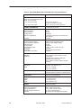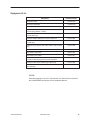
1
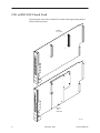
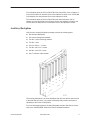
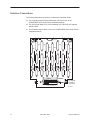
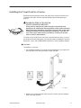
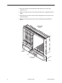
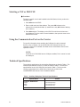
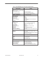
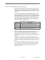
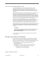
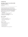
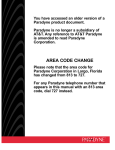
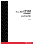
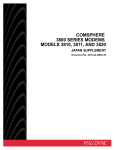
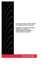
TM
ACCULINK 3151 CSU and 3161 DSU/CSU
General Information Guide
Document Number 3100-A2-GK40-30
December 1998
Introduction
This guide contains general information about the ACCULINK 3151 Channel
Service Unit (CSU) and the 3161 Data Service Unit (DSU)/Channel Service Unit
(CSU). It is designed to be used in conjunction with the COMSPHERE 3000
Series Carrier Installation Manual and the ACCULINK 315x Channel Service Unit
Operator’s Guide or the ACCULINK 316x Data Service Unit/Channel Service Unit
Operator’s Guide.
The Model 3151 CSU and the Model 3161 DSU/CSU are designed to fit into the
COMSPHERE 3000 Series Carrier.
Product Documentation on the World Wide Web
We provide complete product documentation online. This lets you search the
documentation for specific topics and print only what you need, reducing the
waste of surplus printing. It also helps us maintain competitive prices for our
products.
Complete documentation for this product is available at www.paradyne.com.
Select Service & Support → Technical Manuals → T1/E1 Digital Access Devices.
Select the following documents:
Document No. 3000-A2-GA31
COMSPHERE 3000 Series Carrier Installation Manual
Document No. 3150-A2-GB21
ACCULINK 315x Channel Service Unit Operator’s Guide
Document No. 3160-A2-GB21
ACCULINK 316x Data Service Unit/Channel Service Unit Operator’s Guide
To request a paper copy of a Paradyne document:
3100-A2-GK40-30
Within the U.S.A., call 1-800-PARADYNE (1-800-727-2396)
Outside the U.S.A., call 1-727-530-8623
December 1998
1
CSU or DSU/CSU Circuit Card
The front panel of the CSU or DSU/CSU contains twelve light-emitting diodes
(LEDs) and six test jacks.
MODEL
3151 CSU
Se
lec
t
OK
Fa
il
Te
st
Sig
Ne
t
OO
F
m
EE
R
Sig
OO
F
Alr
m
PD
B
BP
V
Alr
DT
E
In
Ne
t
Ou
t
In
Mo
n
Ou
t
In
Eq
p
Ou
t
CS
U
31
51
Se
lec
t
OK
Fa
il
Te
st
Sig
Ne
t
OO
F
m
EE
R
Sig
OO
F
Alr
m
PD
B
BP
V
Alr
DT
R
TX
D
RX
D
CT
S
RT
S
In
Ne
t
Ou
t
In
Mo
n
Ou
t
MODEL
3161
DSU/CSU
In
Eq
p
Ou
t
DS
U/
CS
U
31
496-14949
61
2
December 1998
3100-A2-GK40-30
For information about the CSU or DSU/CSU front panel LEDs, refer to Chapter 3
in the ACCULINK 315x Channel Service Unit Operator’s Guide or the ACCULINK
316x Data Service Unit/Channel Service Unit Operator’s Guide.
For information about the CSU or DSU/CSU front panel test jacks, refer to
Chapter 4 in the ACCULINK 315x Channel Service Unit Operator’s Guide or the
ACCULINK 316x Data Service Unit/Channel Service Unit Operator’s Guide.
Auxiliary Backplane
Verify that the Auxiliary Backplane package includes the following parts:
H
One Auxiliary Backplane
H
Two custom hexagonal standoffs
H
Two No. 6 nylon insulating washers
H
Two No. 5 nuts
H
Four No. 4-40 x 1I screws
H
Two No. 4-40 x 3/4I screws
H
One No. 4-40 x 3/8I screw
H
One T1 network cable retainer
The Auxiliary Backplane is an 8-slot backplane that fits over half the open section
of the 3000 Series Carrier. It is a passive assembly that provides interconnect
capability for the CSUs or DSU/CSUs.
For more information about the Auxiliary Backplane and the 3000 Series Carrier,
refer to the COMSPHERE 3000 Series Carrier Installation Manual.
3100-A2-GK40-30
December 1998
3
Interface Connections
The Auxiliary Backplane provides the connectors for interface cables.
For information about Auxiliary Backplane connectors, refer to the
COMSPHERE 3000 Series Carrier Installation Manual.
The ACCULINK Model 3151 CSU and Model 3161 DSU/CSU are shipped
without cables.
For information about cables, refer to the COMSPHERE 3000 Series Carrier
Installation Manual.
CLOCK IN
DIAGNOSTIC
CHAN
DIAGNOSTIC
CHAN
PORT
PORT
PORT
PORT
1
1
1
1
PORT
PORT
1
1
PORT
PORT
1
1
PORT
PORT
2
2
PORT
PORT
2
2
PORT
PORT
PORT
2
2
PORT
2
2
SLOT 7 (15)
SLOT 6 (14)
SLOT 5 (13)
SLOT 4 (12)
SLOT 3 (11)
SLOT 2 (10)
SLT 8 (16)
SLOT 1 (9)
DTE
DTE
DTE
DTE
DTE
DTE
DTE
DTE
T1 NETWORK
INTERFACE
T1 Network
Interface
Connector
DISCONNECT ALL TELEPHONE LINES AT THE NETWORK
CAUTION: INTERFACE
BEFORE TOUCHING OR SERVICING
496-14364-01
4
December 1998
3100-A2-GK40-30
Installing the Circuit Card in a Carrier
Read and follow all warning notices and instructions marked on the device or
included in this guide. See the Important Safety Instructions beginning on
page 12.
! HANDLING PRECAUTIONS FOR
STATIC-SENSITIVE DEVICES
496-15104
This product is designed to protect sensitive components from
damage due to electrostatic discharge (ESD) during normal operation.
When performing installation procedures, however, take proper static
control precautions to prevent damage to equipment. If you are not
sure of the proper static control precautions, contact your nearest
sales or service representative.
To install a CSU or DSU/CSU circuit card in the 3000 Series Carrier, you must
first install an Auxiliary Backplane. For information about installing the Auxiliary
Backplane, refer to the COMSPHERE 3000 Series Carrier Installation Manual.
" Procedure
To install the circuit card:
1. Use a Phillips screwdriver to loosen the screw holding the circuit pack lock
and rotate the lock to the open position. Open the latch.
2. Hold the circuit card vertically at the front of the carrier, with the faceplate
latch in the open position.
3100-A2-GK40-30
December 1998
5
3. Insert the card into the top and bottom card guides of one of the slots
numbered 1–16.
4. Slide the card into the slot. The ejector latch lifts up as it engages the metal
flange.
5. Press the latch up until it clicks into the locked position to secure the circuit
card in the carrier.
6. Rotate the circuit pack lock back into the closed position and tighten the
screw.
COMSPHERE®
3000 SERIES
CARRIER
CIRCUIT
CARDS
LATCH
CIRCUIT CARD
GUIDES
CO
MS
PH
ER
E
30
00
496-14389-01
6
December 1998
3100-A2-GK40-30
Power-Up Self-Test
After you install the CSU or DSU/CSU in the carrier and connect the carrier to a
power outlet, the CSU or DSU/CSU performs a power-up self-test to ensure that
the unit is in good working order. For information about the power-up self-test,
refer to the ACCULINK 315x Channel Service Unit Operator’s Guide or
ACCULINK 316x Data Service Unit/Channel Service Unit Operator’s Guide.
To display the pass/fail status of the power-up test, use the procedure described
in Selecting a CSU or DSU/CSU later in this chapter, and use the Self-Test
Health command described in the ACCULINK 315x Channel Service Unit
Operator’s Guide or ACCULINK 316x Data Service Unit/Channel Service Unit
Operator’s Guide.
If the LEDs on the circuit card do not light during the self-test, there may be a
failure in the circuit card or in the carrier’s power supply. Install the circuit card in
another working carrier. If it works, or if a second circuit card in another slot in the
same carrier also does not light, check that the power cable is properly attached
and that the outlet is active. Refer to the COMSPHERE 3000 Series Carrier
Installation Manual.
Shared Diagnostic Control Panel
Use the LCD and keypad on the carrier’s Shared Diagnostic Control Panel
(SDCP) to select and access individual CSUs or DSU/CSUs within a carrier.
Carrier Slots 1–16
SDU
1
2
3
4
5
6
7
8
9
10
11
12
13
14
15
16
Select
OK
Select
Key
Alarm BckUp Test
EC
Status
Indicators
F1
F2
F3
Keypad
COMSPHERE 3000
LCD
Display
496-12348a-03
The SDCP includes one LCD, five LEDs, and eight function keys.
The LCD shows messages and menu tree choices. Messages include alarms,
command/test completion, and action in progress.
The OK, Alrm, and Test LEDs reflect the state of the selected CSU or DSU/CSU.
The Bckup and EC LEDs are not used for the 3100 Series products.
The 7-button keypad surrounding the LCD enables you to navigate through the
menu tree and select choices presented on the second line of the LCD. The
eighth key (Select) selects a unit, by slot address, to access through the SDCP.
When you select a particular CSU or DSU/CSU, the OK LED on that unit’s front
panel flashes on and off repetitively.
For more information about the SDCP, refer to the COMSPHERE 3000 Series
Carrier Installation Manual.
3100-A2-GK40-30
December 1998
7
Selecting a CSU or DSU/CSU
" Procedure
To select a specific circuit card installed in the 3000 Series Carrier, perform the
following steps:
1. Press Select on the SDCP.
2. Enter a valid carrier and slot address. The green OK indicator on the
selected circuit card should flash. (It should be the only OK indicator flashing
in the cabinet.)
3. Press Select again. The display on the SDCP should show the last menu
item displayed, or in the case of a new installation, the top-level menu on the
selected circuit card.
Using the Communication Port on the Carrier
For specific information about enabling the COM port for carrier-mounted
devices, refer to Chapter 3 in the ACCULINK 315x Channel Service Unit
Operator’s Guide or ACCULINK 316x Data Service Unit/Channel Service Unit
Operator’s Guide.
NOTE:
If a Model 3161 DSU/CSU has the COM port enabled, Port 2 cannot be used
as a data port.
Technical Specifications
The technical specifications for the Auxiliary Backplane are listed in Table 1. The
technical specifications for the 3151 CSU are listed in Table 2. The technical
specifications for the 3161 DSU/CSU are listed in Table 3. The fan module
cooling requirements for the 3000 Series Carrier are provided in the
COMSPHERE 3000 Series Carrier Installation Manual.
Table 1. Auxiliary Backplane Technical Specifications
Criteria
Specifications
8
PHYSICAL DIMENSIONS
Height
Width
Depth
9.0 inches (22.9 cm)
8.0 inches (20.3 cm)
1.3 inches (3.3 cm)
WEIGHT
2.4 pounds (1.1 kg)
December 1998
3100-A2-GK40-30
Table 2. ACCULINK Model 3151 CSU Technical Specifications
Criteria
Specifications
POWER REQUIREMENTS
Sixteen 3151 CSUs with SDU, SDCP,
and fan module:
115 Vac power supply
– 48 Vdc power supply
POWER CONSUMPTION
DTE INTERFACE
Physical Interface
Framing Format
Coding Format
DTE Line Equalization
3.7 watts per circuit card
Send AIS
DB15S
D4, ESF
AMI, B8ZS
5 selectable ranges from 0 to 655 feet (0 to
196.5 meters)
Selectable
NETWORK INTERFACE
Physical Interface
USA
Canada
Framing Format
Coding Format
Line Build-Out (LBO)
ANSI PRM
Bit Stuffing
Keep Alive to Network
Yellow Alarm Transcoding
RJ48H (T1), RJ48C with adapter cable
CA81A (T1 with adapter cable)
D4, ESF
AMI, B8ZS
0.0 dB, –7.5 dB, –15 dB, –22.5 dB
Selectable
FCC Part 68, AT&T TR 62411
AIS, Framed All Ones, Network Signal Looped
Selectable
LOOPBACKS
Standard
Additional
3100-A2-GK40-30
90 to 132 Vac, 60 Hz ±3
(1.25 amp, 111 watts at 115 Vac)
–60 to –40 Vdc (2.3 amps maximum)
AT&T TR 54016, AT&T TR 62411, ANSI
T1.403.1989
LLB (Line Loopback), PLB (Payload Loopback),
RLB (Repeater Loopback)
APPROVALS
Refer to the product labeling
PHYSICAL DIMENSIONS
Height
Width
Depth
7.1 inches (18.0 cm)
1.0 inches (2.5 cm)
14.2 inches (36.1 cm)
WEIGHT
1.3 pounds (.6 kg)
ENVIRONMENT
Operating Temperature
Storage Temperature
Relative Humidity
Shock and Vibration
32° to 122°F (0° to 50°C)
– 4° to 158°F (– 20° to 70°C)
5%—95% (noncondensing)
Withstands normal shipping and handling
December 1998
9
Table 3. ACCULINK Model 3161 DSU/CSU Technical Specifications
Specifications
POWER REQUIREMENTS
Sixteen 3161 DSU/CSUs with SDU,
SDCP, and fan module:
115 Vac power supply
– 48 Vdc power supply
POWER CONSUMPTION
DTE (DSX-1) INTERFACE
Physical Interface
Framing Format
Coding Format
DTE Line Equalization
90 to 132 Vac, 60 Hz ±3
(2.4 amp, 215 watts at 115 Vac)
–60 to –40 Vdc (4.7 amps maximum)
9.3 watts per circuit card
Send AIS
DB15S
D4, ESF
AMI, B8ZS
5 selectable ranges from 0 to 655 feet (0 to
196.5 meters)
Selectable
NETWORK T1 INTERFACE
Physical Interface (USA)
Physical Interface (Canada)
Framing Format
Coding Format
Line Build-Out (LBO)
ANSI PRM
Bit Stuffing
Yellow Alarm Generation
RJ48H, RJ48C with adapter cable
CA81A (T1 with adapter cable)
D4, ESF
AMI, B8ZS
0.0 dB, –7.5 dB, –15 dB, –22.5 dB
Selectable
FCC Part 68, AT&T TR 62411
Selectable
LOOPBACKS
Standard
Additional
AT&T TR 54016, AT&T TR 62411, ANSI
T1.403.1989
RLB (Repeater Loopback), DLB (DTE
Loopback), V.54 Loop 2 and
Loop 3, ANSI T1.403 Annex B Fractional T1
Loopback
PORT INTERFACE
Standards
Rates
10
Criteria
EIA-530A, V.35, RS-449, V.11
Nx64 – 64-1.536 Mb
Nx56 – 56-1.344 Mb
CLOCKING SOURCES
T1 network interface, Port 1, internal clock, DTE
Drop/Insert (DSX-1) interface, or external clock
APPROVALS
Refer to the product labeling
PHYSICAL DIMENSIONS
Height
Width
Depth
7.1 inches (18.0 cm)
1.0 inches (2.5 cm)
14.2 inches (36.1 cm)
WEIGHT
1.8 pounds (.82 kg)
ENVIRONMENT
Operating Temperature
Storage Temperature
Relative Humidity Shock and
Vibration
32°F to 122°F (0°C to 50°C)
– 4°F to 158°F (– 20°C to 70°C)
5%—95% (noncondensing)
Withstands normal shipping and handling
December 1998
3100-A2-GK40-30
Equipment List
Equipment
Feature Number
Model 3151 CSU
3151-B3-010
Model 3161 DSU/CSU
3161-B3-010
Auxiliary Backplane
3100-F1-900
T1 Network Interface Adapter, 50-pin socket to eight 8-pin
modular plugs (RJ48H – RJ48C)
3100-F1-930
Diagnostic Channel Extension, D8W 8-pin modular plug to
8-pin modular plug
3100-F1-910
COM port adapter, DB25 plug to 8-pin modular jack
3100-F1-920
COM port to terminal adapter cable, DB25 plug to 8-pin
modular plug
3100-F1-540
COM port to PC adapter cable, DB9 socket to 8-pin modular
plug
3100-F1-550
EIA-530-A-to-RS-449/422 Cable
3100-F1-580
EIA-530-A-to-V.35 Cable
3100-F1-570
EIA-530-A-to-X.21 Cable
3100-F1-571
T1 Network Interface Adapter, 50-pin socket to eight 8-pin
modular sockets (RJ45) (Harmonica Block Adapter)
3100-F1-940
Crossover cable, 8-pin modular plug to DB15 plug
3100-F1-590
T1 Network Interface Adapter, 50-pin socket to eight DB15
plug (Canada)
3100-F1-950
NOTE:
Cable descriptions for the 3151 CSU and the 3161 DSU/CSU are located in
the COMSPHERE 3000 Series Carrier Installation Manual.
3100-A2-GK40-30
December 1998
11
Important Safety Instructions
1. Read and follow all warning notices and instructions marked on the product
or included in the manual.
2. When an ac power source is used, this product is intended to be used with a
3-wire grounding type plug – a plug which has a grounding pin. This is a
safety feature. Equipment grounding is vital to ensure safe operation. Do not
defeat the purpose of the grounding type plug by modifying the plug or using
an adapter.
3. Prior to installation, use an outlet tester or a voltmeter to check the ac
receptacle for the presence of earth ground. If the receptacle is not properly
grounded, the installation must not continue until a qualified electrician has
corrected the problem.
4. If a 3-wire grounding type power source is not available, consult a qualified
electrician to determine another method of grounding the equipment.
5. Slots and openings in the cabinet are provided for ventilation. To ensure
reliable operation of the product and to protect it from overheating, these
slots and openings must not be blocked or covered.
6. Do not allow anything to rest on the power cord and do not locate the product
where persons will walk on the power cord.
7. Do not attempt to service this product yourself, as opening or removing
covers may expose you to dangerous high voltage points or other risks.
Refer all servicing to qualified service personnel.
8. General purpose cables may be provided with this product. Special cables,
which may be required by the regulatory inspection authority for the
installation site, are the responsibility of the customer.
9. When installed in the final configuration, the product must comply with the
applicable Safety Standards and regulatory requirements of the country in
which it is installed. If necessary, consult with the appropriate regulatory
agencies and inspection authorities to ensure compliance.
10. A rare phenomenon can create a voltage potential between the earth
grounds of two or more buildings. If products installed in separate buildings
are interconnected, the voltage potential may cause a hazardous condition.
Consult a qualified electrical consultant to determine whether or not this
phenomenon exists and, if necessary, implement corrective action prior to
interconnecting the products.
11. This product contains a coin cell lithium battery that is only to be replaced at
the factory. Caution: There is a danger of explosion if the battery is
incorrectly replaced. Replace only with the same type. Dispose of used
batteries according to the battery manufacturer’s instructions. Attention: Il y
a danger d’explosion s’il y a remplacement incorrect de la batterie.
Remplacer uniquement avec une batterie du même type. Mettre au rebut les
batteries usagées conformément aux instructions du fabricant.
12
December 1998
3100-A2-GK40-30
12. In addition, if the equipment is to be used with telecommunications circuits,
take the following precautions:
— Never install telephone wiring during a lightning storm.
— Never install telephone jacks in wet locations unless the jack is
specifically designed for wet locations.
— Never touch uninsulated telephone wires or terminals unless the
telephone line has been disconnected at the network interface.
— Use caution when installing or modifying telephone lines.
— Avoid using a telephone (other than a cordless type) during an electrical
storm. There may be a remote risk of electric shock from lightning.
— Do not use the telephone to report a gas leak in the vicinity of the leak.
Notices
! WARNING:
THIS EQUIPMENT HAS BEEN TESTED AND FOUND TO COMPLY WITH THE LIMITS FOR A
CLASS A DIGITAL DEVICE, PURSUANT TO PART 15 OF THE FCC RULES. THESE LIMITS
ARE DESIGNED TO PROVIDE REASONABLE PROTECTION AGAINST HARMFUL
INTERFERENCE WHEN THE EQUIPMENT IS OPERATED IN A COMMERCIAL
ENVIRONMENT. THIS EQUIPMENT GENERATES, USES, AND CAN RADIATE RADIO
FREQUENCY ENERGY AND, IF NOT INSTALLED AND USED IN ACCORDANCE WITH THE
INSTRUCTION MANUAL, MAY CAUSE HARMFUL INTERFERENCE TO RADIO
COMMUNICATIONS. OPERATION OF THIS EQUIPMENT IN A RESIDENTIAL AREA IS
LIKELY TO CAUSE HARMFUL INTERFERENCE IN WHICH CASE THE USER WILL BE
REQUIRED TO CORRECT THE INTERFERENCE AT HIS OWN EXPENSE.
THE AUTHORITY TO OPERATE THIS EQUIPMENT IS CONDITIONED BY THE
REQUIREMENTS THAT NO MODIFICATIONS WILL BE MADE TO THE EQUIPMENT UNLESS
THE CHANGES OR MODIFICATIONS ARE EXPRESSLY APPROVED BY PARADYNE.
! WARNING:
TO USERS OF DIGITAL APPARATUS IN CANADA:
THIS CLASS A DIGITAL APPARATUS MEETS ALL REQUIREMENTS OF THE CANADIAN
INTERFERENCE-CAUSING EQUIPMENT REGULATIONS.
CET APPAREIL NUMÉRIQUE DE LA CLASSE A RESPECTE TOUTES LES EXIGENCES DU
RÉGLEMENT SUR LE MATÉRIEL BROUILLEUR DU CANADA.
Government Requirements and Equipment Return
Certain governments require that instructions pertaining to CSU and DSU/CSU
connection to the telephone network be included in the installation and operation
manual. Specific instructions are listed in the following sections.
3100-A2-GK40-30
December 1998
13
Notice to Users of the United States Telephone Network
1. This equipment complies with Part 68 of the FCC rules. On the equipment is
a label that contains, among other information, the FCC registration number
for this equipment. The label is located on the CSU or DSU/CSU circuit card
assembly. If requested, this information must be provided to the telephone
company.
2. There is one type of telephone line associated with this equipment. The T1
network connection should be made using a Universal Service Order Code
(USOC) type RJ48H jack. The Service Order Code 6.0F should be specified
to the telephone company when ordering the T1 line. In addition, the proper
Facility Interface Code must be specified to the telephone company. The
CSU or DSU/CSU can be configured to support any of the following framing
format and line signaling techniques. The CSU or DSU/CSU configuration
must correspond to the T1 line’s parameters.
CSU and DSU/CSU Facility Interface Codes
Code
Description
04DU9-BN
1.544 Mbps superframe format (SF) without line power
04DU9-DN
1.544 Mbps SF and B8ZS without line power
04DU9-1KN
1.544 Mbps ANSI ESF without line power
04DU-1SN
1.544 Mbps ANSI ESF and B8ZS without line power
3. If the CSU or DSU/CSU causes harm to the telephone network, the
telephone company will notify you in advance that temporary discontinuance
of service may be required. But if advance notice is not practical, the
telephone company will notify the customer as soon as possible. Also, you
will be advised of your right to file a complaint with the FCC if you believe it is
necessary.
4. The telephone company may make changes in its facilities, equipment,
operations, or procedures that could affect the operation of the equipment. If
this happens, the telephone company will provide advance notice in order for
you to make the necessary modifications in order to maintain uninterrupted
service.
5. If you experience trouble with this equipment, please contact your sales or
service representative (as appropriate) for repair or warranty information. If
the product needs to be returned to the company service center for repair,
contact them directly as described in Warranty, Sales, and Service
Information on page 15.
14
December 1998
3100-A2-GK40-30
Notice to Users of the Canadian Telephone Network
The Canadian Department of Communications label identifies certified
equipment. This certification means that the equipment meets certain
telecommunications network protective, operational, and safety requirements.
The Department does not guarantee the equipment will operate to the user’s
satisfaction.
Before installing this equipment, users should ensure that it is permissible to be
connected to the facilities of the local telecommunications company. The
equipment must also be installed using an acceptable method of connection. In
some cases, the company’s inside wiring associated with a single-line individual
service may be extended by means of a certified connector assembly (telephone
extension cord). The customer should be aware that compliance with the above
conditions may not prevent degradation of service in some situations.
Repairs to certified equipment should be made by an authorized Canadian
maintenance facility designated by the supplier. Any repairs or alterations made
by the user to this equipment, or equipment malfunctions, may give the
telecommunications company cause to request to disconnect the equipment.
Users should ensure for their own protection that the electrical ground connection
of the power utility, telephone line, and internal metallic water pipe system, if
present, are connected together. This precaution may be particularly important in
rural areas.
CAUTION:
Users should not attempt to make such connections themselves, but
should contact the appropriate electric inspection authority, or
electrician, as appropriate.
If your equipment is in need of repair, refer to Warranty, Sales, and Service
Information below.
Warranty, Sales, and Service Information
Contact your local sales representative, service representative, or distributor
directly for any help needed. For additional information concerning warranty,
sales, service, repair, installation, documentation, training, distributor locations, or
Paradyne worldwide office locations, use one of the following methods:
H
Via the Internet: Visit the Paradyne World Wide Web site at
http://www.paradyne.com
H
Via Telephone: Call our automated call system to receive current
information via fax or to speak with a company representative.
— Inside the U.S.A., call 1-800-870-2221
— Outside the U.S.A., call 1-727-530-2340
Copyright E 1998 Paradyne Corporation
3100-A2-GK40-30
December 1998
15