1
Field Service
Handbook
for Silicon Graphics Workstations
TM
Crimson
IRIS-
i
GreatEastern
T
E
C
H
N
O
L
O
G
Y
Field Service
Handbook
Crimson Workstations
Great Eastern
T
E
C
H
N
O
L
O
G
'
f
Table of Contents
Section I-Specifications
................................................................ 1-1
.................................................................................1-1
Product Description
Features
.................................
.........................
Models
1-2
Systems configuredwith 16 MB of lowdensity memory........1-2
Systems configuredwith 64 MB of high-density memory......1-3
...".....................
EnvironmentaVPhysical Specifications
EmironmenWhysical Specifications
Site and Weight
Power .....................................................................................
Audio Noise
...................................
.....................................................................
............................................................................
1-4
1 4
1-4
1-5
1-5
1
Field Service Handbook for SGI
Cdmson
Section 24onfigurations
.....................................
Displaying the System Configuration
2-2
................................................................ 2-3
Chassis Configurations
Chassis-Front View (without cover)
Chassis-Rear View (without cover)
Chassidackplane (rear view)
Chassis-PS3 Status Panel PCA
Chassis-Card Cage ...
Chassis-Slot Assignments
Slot Assignmentsfor Graphics Subsystems
.....................................
.....................................
............................................
.......................................
.......................................................
.................................................
........................
24
2-6
2-8
2-10
2-12
2-13
2-13
............................................................................. :......2-15
CPU Board
C P W P17 Component Locations
......................................
.........................................................................................
Memory
Memory-Rules for Populating MemorySlots
UO Board
.....................
....................................................................................
.................................................
1038 Component Locations
...........................................................
Graphics Subsystems
SingleBoard Graphics Subsystems
Multiple-Board Graphics Subsystems
Graphics-MGl Adapter
Graphics4332 Motherboard
Graphics-Entry
Graphics-XS
Graphics-XS24
Graphics-Elan
Graphics-Extreme
Graphics-VGXT
VGXT Graphics-Slot Assignments
Graphics-Reality Engine
Reality Engine Graphics-4
lot Assignments
....................................
..................................
......................................................
..............................................
...................................................................
......................................................................
..................................................................
....................................................................
..............................................................
.................................................................
.....................................
....................................................
.......................
.....................................
Monitors
Monitor TerminationSwitches
2-16
2-18
2-19
2-20
2-20
....2-22
2-22 {
2-22
2-23
2-24
2-26
2-27
2-28
2-29
2-30
2-31
2-33
2-34
2-34
................................2-35
............................................
2-35
...................................................................2-36
Peripheral Devices .
Disk Drives
2-36
Tape Drives
2-36
Media Devices.2-36
SCSl Addressing
2-37
Jumper Settingsfor Disk Drives
2-37
Identifying Disk Drives
2-37
..........................................................................
..........................................................................
....................................................................
..................................................................
...........................................
.........................................................
ii
(D
Great Eastern Technology 11/96
t
Table of Contents
Field Servke Handbook for SGI
........................................
Disk D r i v e 1GB 3.5" SCSl-2
Seagate ST11200N
.............................................................
....................2 4 0
................
Disk D r i v e lGB 3.5' SCSI-2
IBM 0663E15
.......................................................................
Disk Drives-2.4GB 5.25" SCSI.2
IBM 0663
.....................
Tape Drives-l.3GB 4mm.DAT SCSI
Archive E4320NT
.................................................................
...............................................................
CD-ROM Drive-644MS
Toshiba XM-3301B
...............................................................
.
240
...............................................2-42
..............................................................................
...
2-38
2.38
242
2-44
2-44
2-48
2-48
Section 3-Operation
.......................
PROM Monitor
Command Monitor
PROM Monitor Environmentals
......................
.................................................................
.............................................
3-2
3-3
34
...............................3-6
............... 3-7
Forcingthe Console to the DiagnosticPort
Bootingthe SySfem............................. u.n.Bootable Files-System Disk Drive
Bootable Files-Media Devices
Run Levels
.......................................
...........................................
...........................................................................
tx
.................*....
3-9
3-10
3-11
................ .......-.................................3-13
"
H
"
.
.
.
.
.
.
.
.
.
.
I
.............................................................................
............................................................................
................................................................
.......................................................................
...........
...........
........................................................
................................................
.........................................................
Bootingfx
Rurning fx
Running fx in lRlX
fx Commands
Formatting and Labelinga System Disk Drive
Formatting and Labelinga Second Disk Drive
Exercising a Disk Drive
Adding to the BadBlock List
ldentrfying Disk Drives
0 Great Eastern Technology 11196
3-13
3-16
3-16
3-17
3-19
3-20
3-21
3-22
3-23
...
111
...............................3-24
integrated Diagnostics Environment (IDE)
Running ID€
:
ID€ Commands
System Configuration Flags
Displaying ID€ Flags............................................................
IDE Flags
Using ID€ to Test the System
Running IDE Test Groups or Subte
sts
......................................................................... 3-24
....................................................... ............3-25
................................................. 3-26
3-26 f
............................................................................. 3-27
.............................................. 3-29
.................................
..
3-31
............, ................................................... 3-32
Testing Power Supply Voltages................................................. 3-33
...
...
Rebuilding the Kernel
.
Section 4-Troubleshooting
.......................................
...............................
..................................
...........
..........
....................................................
............................................
..........................................................
..............................................
.............................................................
.....................................
........................
..........................
...................................
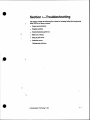
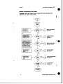
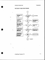
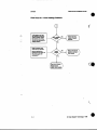
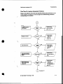
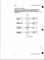
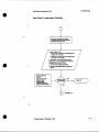
Master Troubleshooting Flow Chart
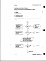
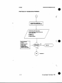
Flow Chart A-System Power Problems
Flow Chart A1 Over Heating Problems
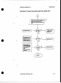
Flow ChartB-Graphics Subsystem Problems
Table El-Troubleshooting Graphics Problems
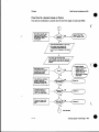
Flow ChartM O S T Fails
Table Cl-System Fails POSTS
By-Passing the POSTs
Flow ChartC l - P O N Testing
Running PON Tests
Flow ChartD--IRIX Boot Problems
Flow ChartDl-System Cannot Boot sash
Flow ChartE-System Hangs or Panics .
Flow ChartF-intermittent Problems
Flow ChartG-Undetermined Problems
.............................
4-2
4-3
4-4
4-5
4-6
4-7
4-8
4-9
4-10
f....
4-11
4-12
4-13
4-14
4-15
4-16
t
iv
(0
Great Eastern Technology 11/96
a
.
Table of Contents
Reld Service Handbook for SGI
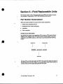
Section 5-Field
Replaceable Units
...............
............................5-1
5-1
:
Part Number Nomenclature
Printed Circuit Assemblies
Peripheral Devices
Assemblies.............................................................................
Cable Assemblies
.....................................................
.................................................................
..................................................................
5-2
5-2
5-2
...........................................................................................
5-3
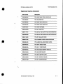
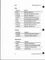
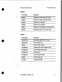
FRU List
....
...............................................................
...................................................
......................................
......................................
..............................................................................
....................................................................
.................................................................................
..................................................................................
CPU-Memory-IO
VGXT Graphics Subsystem
Reality Engine Graphics Subsystem
Single-Board Graphics Subsystems
Drives.....................................................................................
Controllers
Keyboard/Mouse
Monitors
Chassis
Cables....................................................................................
(0
Great Eastern Technology 11I96
5-3
54
54
5.5
5-6
5-6
5.6
5-7
5-7
5-8
V
..
.
Fidd Service Handbook for SGI
CflmsOn
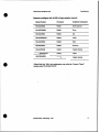
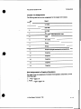
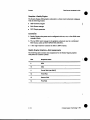
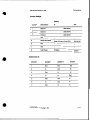
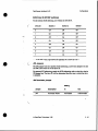
Models
Crimson Series systemsare configured in a number of models basedon the
processor speed (most systems come standard with
R4OOO microprocessor),
installed memory (16 or64 MB standard), and graphics subsystem.
Crimson
systems are also configured as network servers (withouta graphics subsystems).
The section belowlists the model numbersfor standard configurationsof systems
based on the amountof installed memory.All Crimson systems are shipped with.a
1.2GB diskdrive.
Note: The “W6” in the following model numbers denote the single tower chassis
in
which Crimson systemsare configured.
.
Systems configured with16 M B of low-density memory
Number
Model
Processor
Subsystem
Graphics
W6-CRIMS
R4000
WG-CRIMBLG
R4000
Entry
WG-CRIMXS
R4000
xs
WG-CRIMXS24
R4000
XS24
WG-CRIMEG
R4000
Elan
WG-CRIMEX
R4000
Extreme
W6-CRIMRE
R40W
Reality Engine
WWUR16VGr
R4400
VGXT
(sewer)
None
*Note: Before July 1994,this configuration was called the “Jurassic
Classic”
(model number W6-JUR16VGXT).
1-2
cb Great Eastern Technology 11196
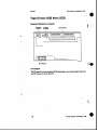
Systems configured with 64 MB of highdensity memory
M o d s 1 Number
Processor
Graphics Subsystem
WWDCR64S
R4000 (server)
None
R4OW
Entry
WWOCRMXS
R40W
xs
W6-4DCR64XS24
R4000
XS24
W6-4DCR64EG
R4OW
Elan
WWDCR64EX
R40W
Extreme
W6-4DCR64RE
R4000
W6-CRIMlSOVGXT
R4400
WG-CRIM150RE
R44W
Engine Reality
VGXT
Engine
Reality
*Note. Before July 1994, this configurationwas called the “Jurassic Classic”
(model number W6-JUR64vGW.
0 Great Eastern Technology 11I96
1-3
Field Service Handbook for SGI
Crimson
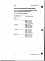
EnvironmentalPhysical Specifications
This section contains environmental and physical specifications for
Chon
systems, whichare configured in a single towerchassis.
EnvironmentaUPhysical Specifications
.................50 to 95°F (10 to 35°C)
Storage temperatart ...........................
14PF (-40 to 60°C)
Operating temperature
...
..
Stze and Weight
C
W ............................................W1dth-2ln
Height-26"
Depth-29"
Weight-180
(54Cm)
(65 cm)
(74 cm)
lbs (82 kg)
19" Monitor ....................................
W~dth-19.2" (49 cm)
Height-21.5" (54.5 cm)
Depth-19.c (49 cm)
Weight48 Ibs (31 kg)
16" Monitor ........... ............
Width-15.5" (39 cm)
Height-16" (41 cm)
Depth-17" (43 cm)
Weight47 lbs (21 kg)
Keyboard
1-4
........................................
(51 cm) .
Height--1.75" (4.5 a)
DCpth4.5" (215 cm)
Weight-3 Ibs (1.4 kg)
W
1dth-20"
.
specifications
Field Senrice Handbook for SGI
Power
Line voltage ....................................
104-132 VAC
200-240 VAC
current ............................................
System-20 amps at 120 VAC
10 amps at 240 VAC
Monitor-2.5 amps at 12OVAC
AC frequency range............
47 to 63 Hz
Input plug........................................ 5-20
Heat displacement
.............
System-2600 BTUs typical
(maximin of 4100 BTUs/how)
Monitor-512 BWs/hour
Audio Noise
Maximum 85db (typical operation)
e
cb Great Eastern Technology 11/96
1-5
....
..,.
.
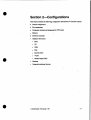
Section 2-Configurations
his Section contains the following configuration informationfor Crimson systems:
Chassis configuration
Slot assignments
Component location and jumpering for CPU board
0
0
Maw
I03B YO contxollcr
Graphics subsystems
.Entry
0
xs
xs24
0
Elan
0
Exame(EX)
0
VGXT
0
Reality Engine (RE)
0
0
Moniton
0
Supported peripheral &vim
(D Great Eastern Technology 11/96
2-1
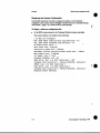
Displaying the System Configuration
Use the hinv (hardware inventory) command to displaylist
a of hardware
configured in the system. Executethe hinv command from the Commbd Monitor
(see Section 3, page 3-3) or from the IRIX system prompt.
To display a hardware con6guration l
ist.
At the I R E system prompt or the Command Monitor prompt, enterhinv.
..
The system displays list
a similar to the following:
1 50 MHz IP17 Processor
FPU: MIPS R4010 Floating Point Chip Revision:0.0
CPU: MIPS R4000 Processor Chip Revision: 2.2
On-board serial ports: 4
Data cache size: 8 Kbytes
Instruction cache size: 8 Kbytes
Secondary unified instruction/data cache size: 1 Mbyte
Main m e m o r y size: 32 Mbytes
1/0 board, slot F: I03B
Integral Ethernet: ctO, I03
Tape drive: unit 6 on SCSI controller1: DAT
Integral SCSI controller 1: Version WD33C93A. revision 9
CDROM: unit 6 on SCSI controller 0
Disk drive: unit1 on SCSI controller0
Integral SCSI controller 0: Version WD33C93A. revision 9
Graphics board: GR2-Elan
.
2-2
(D
Great Eastern Technology 11/96
e.
Field Service Handbook for SGI
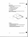
Chassis Configurations
Crimson systems are configured in a single tower deskside chassis, which
is the
same single tower chassis supported by POWER Series systems.
.
14-slot desksidechassis
.Front loading 9U VME card cage
.'
Four front-loading drive bays
W o 5.25"half-height drive bays
W o 5.25" full-height drive bays
0
StahlsPanel
0
On-offswitch
Systemreset switch
Power LED (green)
Fault LED (yellow)
Thermal sensor reset switch
i
Front access to cabling
Blower assembly (located at bottom of chassis)
1050W powersupply
a Great Eastern Technology 11/96
2-3
Field Service Handbook for SGI
CrimsCn
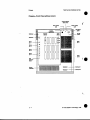
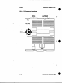
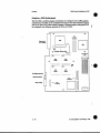
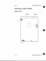
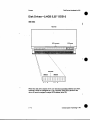
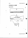
Chassis-Front
View (without cover)
I
,
I
/
....
.
I
2-4
I
FD Great Eastern Technology 11/96
ReM Service Handbook for SGI
Configurations
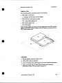
Chassis (Front View)-Comments
1. Fault and powerLEDs. on-off switch, system reset switch, and thermal sensor
reset switch reside on thePS3 status panel PCA(see page 2-10), located behind
s t a t u s panel plate.
2. Power LED remains litafter system is powered-on; indicatesnormal DC power.
3. Fault (yellow)LED is lit and steady during power-on tests (POSTS).After
system passes itsPOSTS,fault LED goes out
. s e l f
...
4. If system fails its POSTS. fault LED remains lii.
5. PS3 status panel PCA contains a one-digit
hex status display, which displays the
following:
0
During power-up, displays steady.“F“
After system passes itsPOSTSand goes into theP R O M Monitor (System
Maintenance Menu), alternately displays“1” and ’2”
After systemboots IRIX,alternately displays“0“and “1”
6. Mode DIP switches also reside on the PS3 PCA and canbe configured to nm
different kinds of diagnostics modes during power-up. For
normal operation, all
switches arc set to “ON. See page 2-1 1 for setting switches to by-pass
POSTS.
7. Thermal reset switch resets thermal sensor,
which is located inthe top of the
single towa chassis.
8. T
h
d sensor (circuit breaker) located
in top of system tower system is shut
down if tempemhare exceeds140O F (a0OC). Thennal sensor can be reset after
system temperaturecools to 104OF (40“C).
9. System supportfour front-loading 5.25“
devices. .
n o half-height drive bays
’ b o full-height drive bays
1O.Full-height drive bays canbe conf@xcd withfull or half-heightdevices.
11.Devices in top drive bays reside
on SCSI bus 1; devices in bottom drive bays
reside onSCSI bus 0.
12TerrninateSCSI buses (0 and 1) using a terminator connected to SCSI ports.
l3.SCSI buses canbe extended to externaldevices using SCSI ports.
..
14.Systems with three BNC connectorssync on green.
15.Keyboard port serial ports reside on PP2 serial YO board.
16.Serial ports 2.3, and 4 have DB9and &pin DIN connectors, whichshare Wiring.
For these serialports, only one connectorat a time canbe used.
(0
Great Eastern Technology 11196
2-5
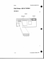
Fidd Service Handbook for SGI
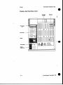
Chassis-fIear View (without cover)
FM
Bdcprrw
t
0 0
J.
000
..
.: .. .\ ..
. ..- .... .... . ... . .
I.
..-- ....
:::=;:::.:.v:: "
~
..
,:.:{ i.:, i .
i::
.1
0
-
0
U
I
L
... .
I
2-6
CD Great Eastern Technology 11/96
@
Field Service Handbook for SGI
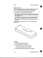
Configuratlons
Chassis Rear VieHF--Comments
1. Power supply circuit breaker controls input power
to power supply.
2. Power bus bar connects+/- 5V from power supplyto backplane.
3. Power supply fan configured with power supply assembly.
4. See page 3-33 for procedures describing howto check power supply voltages.
0 Great Eastern Technology 11/96
2-7
Reid SenriceHandbook for SGI
Chassis-Backplane (rear view)
14
13
12
11
10
0
4
I
.....
.....
.....:
. .
...
...
j
:
.
.
3
2
1
.-...
....- ......
.. ..
.. ..
. .
I
. .
.
...
.."<
,...
.
,-
.
-
.
....
.-
0
0 0
.-
.
:-
. .
0
.
.
:
:
.
.
....."
0 0
... :
. .
. .
. .
. :.
. !
..........
......:
0 0
J11
2-8
. .
0 0
0
J13
Q Great EasternTechnology 11/96
e
L
ReM Service Handbook for SGI
Configurations
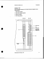
Backplane--Comments
1. The Crimson system uses a multi-processor systems backplane
(FRU# 030-0197-OOx).
2. Remove rear cover and backplane cover access
to
the backplane.
3. Backplane slots comprise thefoilowing buses:
:. .
0
Slots 1 4 = VME bus
0
Slots 5-8
0
Slots 9-14 = Graphics bUS
= mu bus (vo--av)
For slot assignments,see page 2-13.
4. As a general guideline, populate theVME slots from slot1 to slot4.
5. Jumpers located betweenVME slots (14) are bus grant(BG) and intempt
acknowledge (IACK) jumpers. Use the following rules when jumpering the
VME slots:
If any VME slot isempty, BG and IACK jumpers located to the left of the
empty slot mustbe installed,
If a board is installed in a VME slot, the jumpers for that slot
must be
removed
6. If the GENLOCK board is installed in a VME slos itmust reside in slot 4 and the
GENLOCK jumpers (located to the leftof bottom connector for slot
4) must be
inStalled.
7. "he top power bus bar C O M ~ C
ground
~ S from power supply to backplane at
locations J1 land J13.
8. The bottom power bus bar connects
+5V from power supply to backplane at
locations J10 and J12.
9. The connectors on the backplane provide connections
to the following system
components:
Jl-Connects backplane to the PS3 P
C
&located behind status paneL
J Z - c o ~ e ~backplane
ts
to SCSI bus drive bays.
J3--Supplies all power supply voltages to backplane.
J4-Supplies power to PP2 serial I/O board, located on system bulkhead
J6-Supplies power to coolingfans (connects to fan speed controller, located
on backplane).
J7-Connects to thermal sensor locatedin the topof the chassis.
2-9
Field Service Handbook for SGI
Crimson
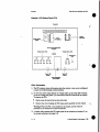
Chassis-PS3
Status Panel PCA
. ...
0 0 0
J
-;+----I
hunm
0
PS-Comments
1. The PS3 displays status information about the system;it also can be configured
to assist in troubleshooting system problems.
2. To view the system stams display or voltage LEDs. set them d e DIP switches,
or use the voltagetest pon
i ts,you must remove thePS3 board from the chassis.
To remove thePS3:
Remove any devices in the top two drive bays.
Remove the screw holding thePS3 status panel assemblyinto the chassis.
Warning: When the PS3 is .not installed in the chassis and the system
is
powered-on, be carelid not to short out thePS3.
3. A ribbon cable connects thePS3 s t a t u s panel to the connector at location J1 on
the system backplane(see page 2-8).
2-10
Q Great Eastern Technology 11/96
t
Field Service Handbook for SGI
Configurations
4. System power switchis used to turn power on and off to the system.
5. System status LEDs-Two system
status L E D s provide systemstatus
information.
Power LED (green-it when system
power supplyis normal.
is powered on and the system's DC
Fault LED (yellow)-Lit
when systemis powered on and while the POSTS
an ruaning; fault LED goes out when system passes
its P O S T S and entcrs the
PROM Monitor or boots the operating system. If the system failsa POST,
fault LED remains lit
..
:.
6. Thermal circuithaler-Trips when the systemair temperature exceeds 140OF
(60"0.
The breaker cannot be nsct until the system temperature coolsto 104 OF
(40"C).The breakerwill also trip if the system sensesa DC voltage thatis 40%
range.
out of
*.
7. System reset Switch-Performs a hardwarereset (power cycle); use only when
all other means of getting controlof the system havebeen tried.
Note: If the system is running IRK, wait at least two minutes before resetting
the systemto give IRIX a chance to sync the disk.
8. Mode DIP switches-Selects the following modes
in which theCPU can run; use
different modesfor troubleshooting the system.
Note. When in the ON position, a DIP switches is down, closestto the PCA
board.
N0rznaI-M switches ON.In nonnal mode, the systemruns all POSTS; if a
fault is not detected the system will boot or enter into the PROM Monitor.
Power+&witches
1 and 8 OFE'In power-on mode,the systemruns all
POSTSand thg! forces the system into the Power ON CpON) mode.
POST bypam4Mtches 3 and 8 OFF. In POST bypass mode, the system
bypasses all POSTS excepted the first memorytess and attempts to enter the
PROM Momtor on serial port 1.
9. System status display-A
following digits:
0
me digit hexLED display, which displays the
Solid F during P O S T S .
Solid F remains displayed is system fails a POST.
Alternating 1's and 2's while system is in the PROM Monitor.
Alternating 0's and 1 when the system is Nnning IRM-
1O.Voltage status LEDs-Voltage status L E D s illuminate when a specific voltage
is
either 10%over thenormal range (OW)or 10%under thenormal range (W>;
see illustration on previous pagefor location of LEDScorresponding to speflc
voltages.
11.Temperanae status-lllumina!es
cp Great Eastern Technology 11/96
when the chassis temperatureis to0 high.
2 - 11
Field Service Handbook for SGI
CrlmsoCr
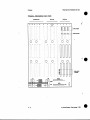
Chassis-Card Cage
..
:
_
1
2
3
4
5
6
7
0
9
10
11
12
13
14
or
CGZ
..
2-12
Q
Great Eastern Technology 11196
4
Configurations
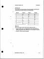
Chassis-Slot Assignments
The following table lists the slot assignments for the single towerchassis.
Slot
Board
1
lstVME
2
Empty
VME
2nd
3
3rd QME
4
4th VME or CG2 GENLOCK
video
5
1038
6
IP17 CPU
7
8
Empty
9
(single-boad
graphics
Graphics
10
Graphics
11
Graphics
12
Graphics
Graphics
13
Graphics
14
subsystems)
Slot Assignments for Graphics Subsystems
For single tower slot assignments for multiple-board graphics subsystems, see the
following pages:
VGXT-pge 2-33
Reality Engine-page 2-34
@ Great EasternTechnology 11/9S
2 - 13
Slot Assignments-Comments
1. See tableon previous page for slot assignments.
2. Card cage is located behiud the system bulkhead.
f
3. Conftgure V M E controller boards in slots 1-4
0
h~tall
VME boards be-g
with Slot 1.
"here must be either aboard installed in a slot orjumpers installed between
the beginning of the VME backplye and the lastVME board (seepage 2-8
for jumper locations).
._...
Slot 4 may contain either aVME board or a CG2 genlockvideo board.
4. The 103B must be
slotinto
install
.
5.
5. The Crimson CPU board must be installed into slot6.
6. The P 1 7 Crimson CPU can not run with MC2 memory board.
7. Single-board graphics subsystems reside in slot9.
8. Boards comprising theVGXT and Reality Engine graphics subsystemare
installed in slots9-14.
2 - 14
0 Great Eastern Technology 11/96
e
Field Service Handbook for SGI
Conlgurations
CPU Board
Crimson systems are configured with a single-processor IP17 CPU board, which is
configured with two different MIPS microprocessors. The microprocessor
is
permanently mounted on the CPU board.
0
100MH~R4000
16 K primary cache (8 K datal8 K instruction)
1 MB secondary cache
...
..
0
15OMHZR4400
32 K primary cache (16 K datal16 K instruction)
1 MB secondarycache
CD Great Eastern Technology 11/96
2 - 15
CfimsOn
'
Reld Service Handbook for SGI
CPU4P17 Component Locations
I
I
C W aacibtor
( 5 0 MHz)
CPU
C W fur
2 - 16
Q Great Eastern Technology11/96
Configurations
Field Service Handbook for SGI
IP174omments
1. The IP17 CPU resides in slot 6.
2. Because theMIPS R4xOO microprocessor runs extremely hot. a heatsink and
cooling fanare mounted directlyon the microprocessor.
3. CPU cooling fanC O M C C ~ to
~ cooling fanpower connector at location JSPI.
4. The P I 7 must run with aI03B YO controller.
5. S u i a l YO connector connectsCPU board to PP2 serial YO panel (containing
keyboard. mouse, andserial ports). which is mounted on systembulkhead (see
page 2-41.
6. When the systemis powered-on or reset. the L E D s on the IP17cycle through the
POSTS.After the systempasses its POST and displays the System Maintenance
Menu, theLEDs display the followingpattern:
7. A&r the systemhas boot the IRIX operating system, theCPU LEDs display the
following pattern during normal operation:
2 - 17
CD Great Eastern Technology 11/96
L
Crlmsocr
Field Sefvlce Handbook b r SGI
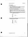
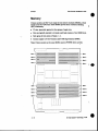
Memory
Crimson systems use 8Ons, 72-pin single in-line memory modules
(SIMMs), which
reside on the IP17 CPU board. These SI"s provide e m r comction checking
(ECC)funtionality.
32 slots, physically organized in four groups of eight slots.
Slots are logically organized in to banks; each bank consists of two S I " slots.
......
Each group of slots consists of banks 1 - 4.
Systems support 2 MB (low-density) and 8 MB (high-density) SIMMs.
Note: Crimson systems use the same SI"s
.
used in POWER Series systems.
- Bonk1
- Bank2
- Bank3
- Bulk4
l l
I
I
............................
..........
..........................................
................. .............
"
.....................................
I '
......................
...............".....-.......
"
._..........
............
.... ........-.
_
I
.
I
1P
-
BMk2
.. ..
Bu*l
4=
- Bulk2
- B.nk3
4P
P
- m4
I
!I
P
I
Bank4
I
i
2 - 18
Q Great Eastern Technology 11196
Reid Senrice Handbook for SGI
Configurations
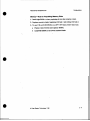
Memory-Rules for Populating Memory Slots
1. Install eight SI"s
at a time, populating a l l slots that comprise a bank
2. Populate consecutivebanks, beginning with bank 1 and ending with bank 4.
3. To mix 2 MB and 8 MB SI"s
on an IP17 CPU board. follow these rules:
Populate a bank with the same-capacity SI"s.
Install 8 MB SIMMs in the lowest numbered banks
(0 Great
Eastern Technology 11/96
2 - 19
field Service H~dboolcfor SGI
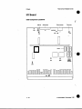
I/O Board
1038 Component Locations
f
...
P
KaQ3
2-20
(0
PROM
Monitor
EPROM.
Great Eastern Technology 11196
e
Conflgurations
ReM Service Handbook for SGI
1. "he I03B board resides in slot 5.
2. The I03B has two SCSI controllers on-board.
3. The I03B has one Ethernet control on-board.
4. For Ethernet andSCSI fuses, use a 2A
125V replacement fuse.
5. Both SCSI controllers use the same fuse.
6. The PROM Monitor logic resideson EPROMs on theI03B.
7. The connectorat location J3 is the connectorfor the secondSCSI controller
(SCSI bus 1).
8. The NVRAM chips holds the PROM Monitor environmental variables, including
the PROM Monitor password aud the Ethernetaddrcss.
9. For normal operation, use thefollowing settings forI03B jumpers:
c2P4
p
J
J408
E l
K8G3
El
M
G7A8
(D Great
Eastern Technology 11196
-
2 21
Crimson
Field Service Handbook for SGI
Graphics Subsystems
Crimson systems can be configured with seven different
graphics subsystems:
Entry
..
..
....
0
xs
e
XS24
0
Elan
Extreme(EX)
VGXT
Reality Engine (RE)
t
Note: The Entry,XS,XS24,and Elan graphics subsystems consist
of the same field
replaceable units (FRUs) as the graphics supported by Indigo systems. The Extreme
graphics subsystem consistsof the sameFRUs supported byIndigc? EX systems.
In both cases, adaptersare required to configure these graphics subsystems in a
Crimson chassis.
Single-Board Graphics Subsystems
The Entry,XS,XS24,Elan, and EX graphics subsystemscan be considered
“single-board” graphics subsystems because they consumeone slot in the Crimson
chassis. However. these graphics subsystems consist
of a motherboard,daughter
cards, and adapter@).
Multiple-Board Graphics Subsystems
of three to five graphics boards.
The VGXT and RE graphics subsystems consist
Boards inthese subsystems havea 9U VME format, and each board consumes a
different slotin the Crimson chassis.
..
..
.. .
2-22
Configurnlions
Field SenAce Handbook for SGI
Adapter
Graphics-MGl
The MGl VME adapter adapts single-board graphic subsystemsto the Crimson's
9U VME format The graphics subsystemfits into the MG1 frame and connects to
the connectoron the MG1PC4 board., which also contains logic ASICs that enable
the single-boards graphics.subsysteems
to run in theCrimson.
..
...................
..................
.......................................
...........
.... "..._.........
. ." ...."..........
..................................
. . . . . . . . .
...................................
.--..-.
:
:.
....
...
,
.:.:.:.,
......3
_..
1
-
MGltnme
':':....
.I...............
....................
...
"
:
........ _.
.,._................
.......................................
..-.... -..."._..
.......
._"
.-__...
.....
:
_
..
:
^"1
.....................................................
f--..:.:::
-
...
...
..............................
..................
"
I
I
uuu
I
I
I
I n 1
I
-'
-.....
.......
...__....
.-..
.-...........
......
-'x
-
Mol
PcAboud
Comments
1. The MGl is requiredto adapt all single-board graphics subsystems(Entry, XS,
XS24.Elan, and EX)to a Crimson chassis.
2. The video cable for single-board graphics subsystems connects the subsystem
to
a 13W3 connector mounted on the system bulkheadat the frontof the chassis.
3. Any ejector clipson an LG2 or GR2 board must be nmoved before those boards
can be installed in the MG1 adapter.
CD Great Eastern Technology 11/96
-
2 23
SGI
ClimsOn
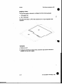
Motherboard
The XS, xS24,and Elan graphics subsystems are configured with a GFU graphics
Graphics-GRZ
motherboard. The GR2 can be configured with one or four GE7 Geometry Engines
and one or three VM2 video memory modules.Merent graphics subsystems will
be configured with different quantitiesof GE7s and VM2s.
BD
@
. ._.
Conmctorto
MG1 adapter
d
'
I
1
'
....."".."-..:. ;
w
.
. .
I I
2-24
II
-.nn
(0 Great
I IIII
Eastern Technology 11/96
Field Service Handbook for SGI
coilflguranons
3. In graphic subsystemsconfiguredwith one VM2 memory module,the vM2must
reside in location P14.
...
4. For normal operation,jumper at location P% must be installed (jumper is used
for manufacturing testing).
5. If using a GR2 graphics motherboardfrom an Indigo,the ejector clips mustbe
removed before installing the GR2 into the MG1 adapter.
Q
Great Eastern Technology 11/96
Crimson
Field Service Handbook for SGI
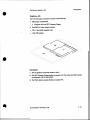
Graphics-Entry
The 8-bit Entry graphics subsystemis configured with the following boards:
0
LC2 graphicboard
MG1 VME adapter
The LG2 board contains a 13W3 video connector anda 15-pin composite video
connector.
Comments
1. Resides in slot 9.
2. If using an LG2 from an Indigo system, the ejectorclips must be removed to
installed LG2 into MGl adapter.
2 -26
Configurations
Field Service Handbook for SGI
Gmphics-XS
The 8-bitXS graphics subsystem consists of the following:
GR2 graphics motherboard
Configured with one GE7 Geometry Engine
OneVM2 8-bit video memory module
.
0
...
...
VB1.l Video Buffer daughter card
MG1 VMEadapter
., .....'. . ............
Comments
1. The XS graphics subsystem resides in slot 9.
2. The GE7 Geometry Engine resides
in location U43.The otherthree GE7 sockets
are jumpemd with an interconnect
3. The VM2 memory module resides in location P14.
(0
Great Eastem Technology 11/96
2-27
CfimsOn
Reid Service Handbook for SGI
'
Graphics-XS24
The 24-bit XS24 graphics subsystem consistsof the following:
GR2 graphicsmotherboard
Configuredwith one GE7 Geometry Engine
ThreeVM2 8-bit video memory modules
VBl.lVideoBufferdaughtercard
0
MGlVMEadapter
No& The XS24 graphics subsystemis the same configuration as the XS with the
addition of two VM2 memory modules.
.
Comments
1. The XsP graphics subsystem residesin slot 9.
2. The GE7 Geometry Engine residesin location U43.The other three GE7 sockets
are jumped with an interconnea
3. The systemwill operate with one VM2 memory module (with downgraded
performance); single VM2 must residein location P14.
i
-
2 28
(D
Great Eastern Technology 11/96
Field Service Handbook for SGI
Configurations
Graphics-Elan
The %bit Elan graphics subsystem consists of the following:
GR2 graphics motherboard
Configured with four GE7 Geometry Engines
Three VM2 8-bit video memory modules
. ._.
0
VB 1.1 Video buffer daughter card
0
ZB4Zbufferda~ghter~d
0
MGl V M E a d a p ~
Note:The Elan graphics subsystem is the same configurationas the XZ24 with the
addition of thee GE7 Geometry Engines
on the GR2graphics motherboard and the
ZB4 Z buf€er daughter card.
Comments
1. The Elan graphics subsystem resides in slot 9.
2. All four GE7 sockets arc populated.
3. System will operate without ZB4 daughter card (with downgradedperformance).
4. System will operate with oneVM2 memory module(
withdowngraded
performance); single VM2 must reside in location P14.
cp Great Eastern Technology11/96
2-29
crimson
Field Service Handbook for SGI
Graphics-€xtreme
The Extreme(EX) graphics subsystem is a three-board graphics subsystem, which
requires two adapters that enableit to be configured in a Crimson chassis.
GUl graphics unit-Contains
eight GE7 Geometry Engine ASICs.
RUl raster unit-Contains two RE3 raster engine ASICs.
VB2 video board-Conrains the 13W3 video connector. GENLOCK connector,
and a connectorfor graphics options suchas stereo glasses. The VB2 also has a
video expansion pon
AB 1 G I 0 adapter-Adapts EX graphics subsystem (physically and logically)
to
MG1 adapter.EX boards connectto A B 1 , which is connected to the MG1.
MG1 VME adapter-Adapts
VME format.
EX subsystem andAB 1 adapter to Crimson’s 9U
Note: The EX graphics subsystem(GUl, RU1, and 0 2 ) is also supported by
Indigo2 systems.
Comments
1. The EX graphics subsystem residesin slot 9.
2. RU1 and VB2 boards do not have connectors
RU1 board connects to GU1 board (two connectors)
VB2 board connects to RU1 board (two C O M C C ~ ~ ~ S )
3. All three graphics boards must be installed for systemto operate.
2-30
0 Great Eastern Technology 11/96
Configurations
Field Service Handbook for SGI
GraphiCs-VGXT
The VGXT graphics subsystemis a four-board subsystem configuredwith the
following boards:
.
GM3 Graphicsmanager
GE6 GeometryEnginesubsystem
RM3 Raster manager
DG1Displaygenerator
GM3 GE6
I
\
I
GI3
I
RM3 OG1
I
I
1
-
I
(D
Great Eastern Technology 11/96
-
2 31
Field Senrice Handbook for SGI
Crimson
VGXT-Comments
1. To view the power-on diagnostics
for the graphics subsystem, connect
an ASCII
terminal to theDB9 connector on the GM3 board. To enter thePROM Monitor,
enter the terminal’s“Break” key sequence.
2. While in the PROM Monitor (after system successfully passesits POSTs), the
eight L E D s on the GM3 board will display the following pattern:
.....
.
0 =On
0
=on
.
3. The GI3 edge connector connects theGM3 to the GE6 board.
4. The RIS edge connector connects one or
two RM3 boards to the DGl board.
5. VGXT graphics require one RM3 boar& systems can be configured
with a
second RM3 board.
6. The RM3 has a 36-LED status display. After the system successfully completes
its POSTS,these LEDs display the followingpattern:
1 -
8 -
16
-
36
-
0
=on
0
-on
..
2-32
CD Great Eastern Technology 11196
Configurations
ReM Sewice Handbook for SGI
7. The DG1 board has five video YO connecton (from topto bottom):
.
0
.
.
.
GENLOCK SWC Output
Alphaoutput Video
RGB Video output and sync to monitor (use internal RGB ribbon cable,
FRU# 018-0183-001)
Super VHS and composite video (useon systems with EV1 video option)
GENLOCKRGB input
._.
.
Assignments
VGXT Graphics-Slot
The following table containsslot assignments forthe VGXT graphics subsystem for
crimson systems:
Slot
Graphics board
11
Optional video
13
First RM3
~
DG1
14
(0
Great Eastern Technology 11/96
2-33
CIimsOn
Field Service Handbook for SGI
GraphicHeality Engine
The Reality Engine(RE) graphics subsystem is a three-board subsystem configured
with the following boards:
i
GE8GeometryEngine
RM4 Raster manager
DGZ Displaygenerator
Commek
1. Reality Engine subsystems canbe configured with one,two, or four RM4 raster
manager boards.
.
2. The last RM4 raster managerin the graphics subsystem must
be a terminated
RM4 board, called an RM4T (FRU# 030-2360-001).
3. A DI1 edge connector connects theDG2 to RM4 board(s).
Reality Engine Graphics-Slot Assignments
The following table contains slot assignments for the Reality Engine graphics
subsystem forCrimson systems:
Slot
r' ..
Graphics buad
e:
1..
9
GE8
10
DG2
11
Fourth RM4 (useRM4T)
12
Third RM4
13
Second RM4
14
First RM4
-
t
2-34
Q Great Eastern Technology 11/96
L
Field Setvice Handbook for SGI
Configurations
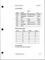
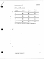
Monitors
See the following table for compatibility information for monitors supported
by
Crimson systems:
Input
Si20
Manufacturer
16"
any
19'
Hitachi
19'
Manufacturer
Model #
SGI FRU #
Connector
CM2086A3SG
9330042
BNC
Hitachi
CM2086A3CD
9330043
BNC
1
Mitsubishi
HL7965KW-SG
9330812
BNC
19'
any
GDM-POD1 1
9330818
13W3
19'
Sony
GDM-1930SG
9330041
13w3
BNC'
933OO40
GDM-163OSG
~~
9'
Note: Momtom with the manufacturer model number ending with
" S G have an
SGI logo on the front bezel. Monitors with
"CD" in the model number do not have
an SGI logo.
MonitorTermination Switches
Most SGI monitors witp BNC input connectors havem
i p
e
d
a
n
e switches usedto
tcxminate the video signals. Thesetennination switches are a push-button. toggle
type usually located under eachBNC connector. Switchescan be set in the
following two positions:
When the switch is in the "in" position (75 ohm), the signal is terminated.
When the switch is in the "out"p0sition (High),the signal is not terminated.
For single-monitor systems.all switches should be set
in the "in" position so that
video signals are terminated W
i
t
h daisythained monitors, only the last monitor
should beterminated.
If a monitoris incorrectly terminated the color may
be incorrect or the video
display may be distorted. When troubleshootinga monitor problem, makesure the
tcxmination switchesarc set correctly, depending
on the specific configuration..
@ Great Eastem Technology 11/96
2-35
Crimson
Peripheral Devices
This section includes drive ID and jumpering information for the S a peripheral
devices supportedby Crimson systems.
(
Disk Drives
. ...
1.268
3-0570-001
Seagate
01ST11200N
1.268
IBM W E 15
2.4GB
IBM 0663 2.468
041-0062-001
(941 0824)
-001 3-0571 01
Tape Drives
Capacity/Format
ManufacturerModel #
SGI FRU Number
1.368 DAT
Atchive E432ONT
01 3-8451
-001
5.OGB 8mm
ExabyteM&8500
041-0011-001
Media Devices
-
Device
Manufactumr/Model Y
644MB CD-ROM
Toshiba XM-3301 B
2 36
SGI FRU Number
Field Service Handbook for SGI
Configurations
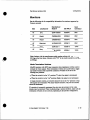
SCSI Addressing
The following table shows the typical drive
IDS used for addressing SCSI devices
on SGI systems. Useas a guide when addressingSCSI devices or determining drive
ID for installed devices.
Comments
Driw ID
Device
1
Disk
The
system
disk
drive
(foot
drive)
is
always drive ID1
..
DiskoftapeAlternativedriveID
for tapedrives which
typically use drive ID
7
2
drive
3disk Optional Disk
drive
4disk
Optional Disk
5disk Optional Disk
drive
~~
~~
~~~~~
6
~
~~~
~
6; other
CD-ROM
CD-ROM
ID
typically
drive
uses
drive IDScan be used
7
Tape
Tape drives typically use
drive ID 7; drive
ID 2 is alternative address
Note: Drive ID 0 is reserved for the SCSI controller.
Jumper S d n g s for Disk Drives
For Crimson systems, set jumpers so that
Parity is enabled.
Spindle motor starts on command.
SCSI bus is tcnninated on last drive.
See information on individual drivefor locations of appropriate jumpers.
Identifying DiskOrlves
Use the fx utility to identify the manufacturer and manufacturer’s model
of disk
drives installed in the system. For information aboutfxusing
to identify disk drives.
see Section 3, page 3-23.
(D
Great Eastern Technology 11/90
-
2 37
Field Service Handbook for SGI
Crimson
Disk Drives-1 GB 3.5" SCSI-2
Seagate ST11200N
scsl
CQlmrm
S c s l Rmrr
I
I
I
..
1
Pill' 1
+
.
JS
0
1
J2
8
0 0
0 0
0 0
TP
TP
zz
ss
0 0
5 0
0 0
ME
Ds
Rs
J6
LED
F3
-
4
m1
i
2-38
a3 Great Eastern Technology 11/96
*
Configurations
Field Service Handbook for SGI
J2 Jumper Settings
Setting
Description
In
Tp (2)
Termination power
term.
Term.
drive
Not
power
to
ss (3)
Reserved
-
Yes
PE (4)
p=w
Enabled
Disabled
wp (5)
Write protect
Enabled
Disabled
ME (6)
Motor start
Wait for start command
No delay
Jumper
..
.
Out
SCSl Drive ID (JB5 jumpers)
Drive ID
Jumpr 1
Jumper 2
Jumper 3
1
In
out
out
*
out
out
3
In
In
out
4
Out
out
In
5
In
out
In
6
Out
In
7
In
In
-
In
In
J6 Jumper Settings
Leave all pins on the J6 jumper block unjumpered.
CD Great Eastem Technology 11196
2-39
Field Service Handbook for SGI
Disk Drives-I GB 3.5" SCSI-2
IBM 0663E15
. .
1
\
~~
\
,
'
\
\
I
0 0 0
0 0 0 0
0 0 0 0 0 0 0 0
1 2 3 4 5 6 7 6
2-40
Q Great Eastern Technology 11/96
111
Field Senrice Handbook for SGI
Configurations
Jumper Settings
Setting
Jumper
In
Description
Out
1
ID
SCSl
(see below)
2
ID
SCSl
(see below)
3
ID
SCSl
(see below)
-
4
WA
5
Motor start delay
Delay
6
WA
7
8
(10 s8c.x drive ID#)
Wait to start
WA
-
-
LED Power
Enabled
Disabled
SCSl Drive ID
Drive ID
Jumper 1
Jumper 2
Jumper 3
1
Out
out
out
In
Out
out
3
Out
In
out
4
In
5
out
6
In
2
~~~
In
7
In
~
~~~
Out
0 Great Eastern Technology 11/96
out
-
Out
In
out
In
In
-
Disk Drives-2.4GB
5.25" SCSI-2
IBM 0663
..
...
\I
..
...
.
0 0 0 0 0 0 0 0 0 0 0 0 0
0 0 0 0 0 0 0 0 0 0 0 0 0
Note: This disk drive consists of two 35" hard disk assemblies (HDAs) and a PCA
controller, which are configured in a 5.25" enclosure. Each HDA (device A and
device B) must be assigned a unique SCSI address (drive ID).
2-42
0 Great Eastern Technology 11198
SCSI Drive ID
Use the table below and the illustration on the previous page to set SCSI drive ID
for both &vias. Each device must have its own SCSI address. .
( -.::.'...'
....
....
Drive ID
Jumper 0
Jumper 1
Jumper 2
1
Out
Out
Out
2
In
Out
Out
3
Out
In
Out
4
In
In
out
5
out .
Out
In
6
In
out
In
7
Out
In
In
Motor Start
The motor start jumper controls w.henthe drives' spindlemotors spin-up.
..
'
(:._
-..
0
~mnper
~,.+bhys @-up 10 seconds times the d r i ~ e ' sSCSI drive ID(for
example, spin-up for drive with a SCSI ID set to 3 will be delayed 30 seconds).
Jumper Out-Waits
for start unit command
..
CD Great Eastern Technology 11/96
2-43
field Service Handbook Rr SGI
CrlmsOn
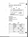
Tape Drives-1.3GB
4mm DAT SCSI
Archive E4320NT
:....
-.-.-:
-..:.:..
I
JP6
=I’
:::
on
00000000000
00000000000
SW1-l
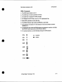
SW1 DIP Switches
Set the DIP switches for the following:
0
..
ScsIaddnSsing
Appropriate SCSI mode (SCSI or SCSI-2)
Parityenabled
0
self test disabled
~~~
.
~~
~
1
S a l addressing
(see below)
2
SCSl addressing
(see b e l o w )
SCSl addressing
Wow)
3
4
SCSl mode
Scsl
Scsl-2
5
M
Y
t
DsaMe
Enable
.
6
7
N/A
0
Self testing
2-44
,
set to Off
set to Off
D i e
(D
Enable
Great Eastern Technobw 11196
SCSI Drive ID (SW1 DIP switches)
To use external SCSI addressing, set switches to drive ID 0.
(off
Drive ID
switch 3
0
off
1
On
switch 2
switch 1
off
off
off
2
_.
On
...
.
3
off
On
off
On
On
off
On
4
5
6
On
off
On
7
On
On
On
N o h On SGI systems, tapedrives & typically set to drive ID 2 or 7.
_..
:
(;-....
JP6 Jumpers
The JP6jumper block also specifies SCSI addressing. Leave these jumpers out and
use SW1 DIP switches to set the drive ID.
For externalSCSX addressing. attach the SCSI addressing cable on the drivesled to
JP6jlrmperbaakThe~eIDwillbedetcrmiaedthedrivebayinwhichtheQive
i
s
i
n
s
t
a
l
l
e
d
JPllTminatlon dumper
..>:
. JP4
Terminator Power
Terminated
Untenninabd
....:
/
0 Grea! Eastern Technology 11/96
2-45
Field Servke Handbod< for SGI
CllmsOn
Tape Drives-5GB
8mm SCSI
Exabyte EXB-8500 (Full Height)
SCSloomaor
I
I
'
...
. ..
:
.:'.
..
I I
II
P3 Jumpers
The P3jumperblock also specifies SCSI addressing. Leave thesejumpers open and
UseDIPswitchcstosetthedriveID.
. . ..
..
..
:i.
...-.
..
c
2-46
0 Great Eastern Technology 11/96
A
Configurations
Field Service Handbook for SGI
SCSl Drive ID (DIP switches)
(-
..
. -. .
Drive ID
Switch 1
Switch 2
switch 3
1
On
off
off
2
off
On
off
3
On
On
off
4
off
off
On
5
On
off
On
off
on
On
On
On
On
7
Note: On SGI systems, tape drives are typically set to drive ID 2 or 7.
i
.
. ..
..
.....'
.
e
.
-
Q
Great Eastern Technology 11/96
2-47
CfimsOrr
-
CD-ROM D r i v p M B
Toshiba XM-3301B
f
.. ..
..
..
..
I
I
~ 0 0 0 0 0 0 0 0 0 0 0 ~
J7
000000000001
Jo
1
-.-
c
2-48
(D
Great Eastern Technology 11/96
4
Reld Senrice Handbook for SGI
Configurattons
SI Jumper Settings)
Sating
f
Jumper
Description
In
.
ID1
..
.--..
Out
(seebelow)
ID2
SCSl addressing
(see below)
ID4
SCSl addressing
(see below)
parity
Enabled
parity Checking
Disabled
Power
Termination
Terminator
TeFinated
Untenninated
SCSl Drive ID
(..
In
Drive ID
Jumper ID1
Jumper ID2
J u m p ID4
1
In
Out
out
2
Out
In
out
3
In
4
Out
out
In
5
In
Out
In
out
In
6
In
In
7
In
Out
In
47 Great G s b m Technology 11/98
2-49
:.:.:+
_.
..
..
..
..
....
.:::::. -
Section 3-0peration
"his section is a quick reference to system level software used in rhaintaiaing and
aoubleshooting Crimson systems.
This section also includes aprocedure for testing
(
power supply
voltages.
PROMMoaitor
Command Monitor conman&
.......
-..
PROM
Monitor
.:.e.
Environmentals
Forcing console output to the Diagnostic Port
Booring the system
... ..
Standalone shell (sash)
0
f .
..
._
'
0
B0oting-h
0
sash C ~ m ~ ~ a n d s
fk (disk drive format a d exercise utility)
0
Bootingfx
0
f
k
X
C
c
r
m
m
x
n
d
s
0
Runningfx
Formatting and labelhg tfie disk drive
0
Adding bad blocks to the bad block list
0
I&n~gdiskdriVes
0
.
\. . . . .
...
0
Using Integrated Di-o~ti~l -at
0
ReMdhg the loernel
WE)
Testing power supply voltages
.-_
..
:.:.
i
(0 Great
Eastern Technology 11/96
3 -1
fleld Service Handbook k r SO1
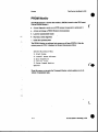
PROM Monitor
e
The PROM Monitor is finnware that resides in PROMS located on the CPU board.
Use the PROM Monitor to:
Access diagnostic console on an ASCII terminal (connected to serial port 1)
Access and change the PROM Monitor environmentals
::::;e.
Load the standalone shell (sash)
Run basic system diagnostics
... .
0
Install the operating system
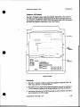
The PROM Monitor also perfoms basic power-on self tests (POSTS).After the
system passes its POSTS,it displays the System Maintenance Menu:
Syntem
Maintenance
Menu
1) Start System
2) Install System Software
3) Run Diagnostics
4) Recover System
5 ) Enter Comrmand Monitor
Option?
ci
-.
From this menu, you can enter the Command Monitor, which enables you to do
variety of maintcnaIlce tasks.
....:.
....
.-.
.....
i
3-2
Field Service
SGI Handbook for
Operation
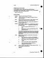
Command Monitor
To enter the Command Monitor,from the System Maintenance Menu, enter5 The
system displaysthe >> prompt.
(
To display the Command Monitor commands:
At the >> prompt, type help and p s s <Return>.
The system displaysthe following commands:
performs an automatic boot
..
.. ..
Boot a specified boot device and file (seepage 3-7for boot
commnnd syntax).
Exits Command Monitor; returns system to PROM Monitor.
Displays Command Monitormenu: also displays information on
specific command(help command).
Writes current environmentah to non-volatilememory 0.
Use init after changing an environmental.
Note: After using hit,the resetenv command will not reset
ewironmentalsto previous values.
Displays list of installed hardware; does not list nonSCS1 devices.
Use to password protect the PROM Monitor.
Displays m n t setrings for PROM Monitor cnvironmen&.
(See
the next page for descriptions.)
Resets the password fa0 enhy into the FROM Monitor.
Usedto change PROM Monitoremrironmental
(setcw mvimnmmtal valrcc).
Reverts PROM Monitor ewimnmental to previous value
(unsetenv e n v i m m w ; does not work if you used init
command after changing environmental.
The copy commaad can be used to copy devices
Displays the PROM Monitor revision and the system's CPU type.
Displays the error correction checking (ECC)memory log. Use the
following syntax:
ecc 1
Displays ECC log
ccc 0
Clears ECC log
0 Great Eastern Technology 11/96
1
3-3
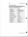
PROM Monitor Environmentals
Use &e pMtem command to display the following PROM Monitor
environmentals and their ament values. To change the value of an enhmmental,
use the setenv command and the following syntax:
setenv envimnmental value
Environmentals
netaddr
Displays the system’s Internet (P) addnss.
dbaad
Displays the baud rate for the diagnostics terminaL which you
attach to serial port 1.
rbaud
Displays the baud rate for serial port 2, which connects to a dbx
terminal used for finding bugs in the operating system.
bootfile
Displays pathname of file used to boot the system; default file is
the standalone shell(sash).
. :.‘.
:
bootmode Specifies type of boot performed by the PROM Monitor afterthe
system completesits POSTS.The bootmode environmental has
two possible values:
C
Cold boot; system boots IRIX when powered-on or
rcset
m
PROM Monitoc system enters PROM Monitor when
powend-on or reset
occurs.
The bootmode environmentalalso indicates when an error occur^
d u h g power-on diagnostics. When an cxror
ane replaces
the bootmode value and remains the cumht value until changed
backtocorm.
console
root
Displays device configured as system console. Use one of the
following settings:
d
Selects serial port1 as console; used for displaying
diagnostics on ASCII terminal connected to serial port1
g
Selectsgraphicsmonitor
console
G
Same as g, but enables system to display SGI logo
b
Selects both graphicsmonitor and serial port 1
(diagnostics) as system console
and keyboard as system
Points to locationof root partition on system disk drive; use the
following path for
SCSI disk drives:
dksodlso
3-4
(0 Gmat Eastern Technolosy
11196
Reid Sewice Handbook for SGI
monitor
Operation
Spemiies scan rate of graphics monitor,available settings include:
60 (60M H z is default)
30
Utsc
Pd
343
sync-on-gmtn
diskless
Specifies the sync signal for the monitor.
Indicates whether or not system has a disk drive:
1 = no disk drive
0 = installed disk
Pa*
Points to location of thevolumeheaderonsystem
the following path for SCSI disk drive:
disk drive; use
dLsC(o91a
dboodile
Points to location of standalone diagnostics program: default is
DE.
c..
.
gslr
Indicates whetherornot PROM Monitor sees graphics subsystem
and keyboard If system does not see graphics or keyboard the gfx
environmental displays dead
a
or no keyboard value.
i
0 Great Eastern Technology 11/96
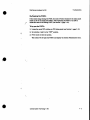
Forcing the Console to the Diagnostic Port
If you do not have control of the graphics console(monitor maybe unreadableor
blank and system will not acceptcommands from keyboard), it may be nuxssary to
force the consoleto the diagnostic port.
To force console output to the diagnostics port:
.*.:.;
.-.-..
1. Install an ASCIl terminal to serial port1 of the system.
2. Configure the terminal for 9600 baud, 8 bit 1 stop bit no parity.
3. Power off system and disconnect the keyboard.
..
4. Power on system.
5. To enter the Command Monitor, from the System Maintenance Menu, enter5
The system displays the >> prompt.
6. To set console environmental to diagnostics, at the Command Monitor prompt,
enter setenv console d.
7. At the Command Monitor prompt, enterinit
8 Power off the system a d reconnect the keyboard.
9. Power on system.
..
The ACSII t
e
m connected to serial port 1 is now the system console.
...
.
..
..
...
..
..
c
3-6
0 Great Eastern Techndogy 11196
opetauon
Field Service Handbook far SGI
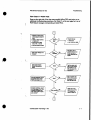
Booting the System
(
Manual booting from the PROM Monitorallows you to select theboot device and
the boot program. This enables youto boot the system using
devices and programs
Merent from the system disk drive and standard boot program.
To boot the system manually, use boot
the command in the Command Monitor and
the following syntax:
._.
t.'..
..
device(x,y,2 ) filename [arpumenel
boot [ - f a ]
-P
prevents PROM ~ o & t ofrom
r using boot program specified in
boottUe environmental (since default setting for bootfde points
to sash, -f option prevents system from loading sash)
-n
Allows system to acccss disk drive, locate bootprogram and loads
it into system memory,but does not executeboot program.
device
Indicates the type of boot device. Possible boot devices include:
..
..
dksc
SCSI disk drive (includes CD-ROM)
tpsc
SCSI tape drive
(QIC)
bootp
Network
tpqic
VME tape drive (QIC)
-
Specdies controller, device address, and partition
X
Selects the controller
Y
Selectsthe device address (SCSI disks start at drive ID 1)
z
. Selectspartition where boot program is located
Name of boot 6Ie being loaded by thePROM Monitor. Files
include.
sash
Standalone shell
fx
Disk drive format and exerciseutility
ide
Integrated
Diagnostics
Environment
S a table on next page for a list of bootable files and bootable
devices.
.-:.'
'.
....
.
Q Great Eastem Technology 1llgs
3-7
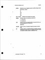
inimate
specifies the system init s a t e (alsocalled run level).
Use format intimate=r, where x is the speclfied run
level. See table on page 3-1 1 for descriptions of run
levels).
(
showcodg Displays the system configurationwhile system is
booting up. use the formatshoweonfig=istrac
...._
. -..
;.; 1.
..
- ....._
.-...
....
....’
c
3-8
Field service Handbook for SGI
operation
,”
I
.-.-.-.
-.-.
..
:.
...
.
..
..
+>
3-9
Field Service Handbook b r SGI
ClimsOn
2:::::
.. .
.....
..
ffj
c
3-10
‘...
(0
Great Eastern Technology 11196
*.
Run Levels
Run bvsl
:
\
:....._
9
Description
mode
user
Single
0
System is shut down or in PROM Monitor mode
1
Singleuser mode
2
s his is the normai tun level for multl wer mode
3
Muftiuser mode
network
(with
4
Alternate run level for multiuser
5
Special run l e v e l for system admin uses
6
System reboot
..
..
disa#ed)
...
.
...
3 -11
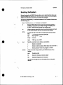
Standalone Shell (sash)
The standalone shell (sash)contains commands used to perfoxm system
maintenance.
To boot sash:
At the >> prompt. use the following format:
boo+ -f device (x, y, z)filename
Use the bootable file tables on page 3-9and page 3-10 for the applicabledevia,
file location, and filename.
. ...
.
..
If the bootfile environmentalpoints to sash-typically located at dksc(0,1,8) on
SCSI drive- the
>> promps enterboot.
After you boot sash, the system displays
the sash: prompt
sash Commands
Use the help command to display thefollowing sash commands:
boot
w
e
d
Boots spedied program on
device; similar to the boot
command in the Command Monitor.
Example: boot -f dkrc(O,l,S)fx
cat
Reads a file and displays it on standard output device.
Example: cat dk.c ( 0 ,1,6) /rQn/SYSLoQ
COPY
Use to copy tiles or file systems; copies block by block
Example: cp dk.~(0,1,1) dk.c(O,l,l)
..
go
Executes the listed bootedprogram into memory.
help
install
Displays thesash commands and their syntax.
Is
List files and directoriesin the UNM. file system.
Loads the installation tools.
Example: Is dlUc((4&0)/
printeJlv
Displays thePROM Monitorenvironmental variablesand their
cumm v
au
les.
setarv
Use to set an e
n
v
r
o
ib
a
ti
variable.
ansctenv
Use to revert a PROM Monitor environmental variableto its
previous vau
l e.
version
Displays PROM Monitorversion and the system’sCPU tupe.
3 -12
(D
r
Great Eastern T ~ n o l o g y11/96
Field Service Handbook for SGI
Operation
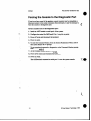
fx is a formatting and exercise utiIity used for basic maintenance an disk drives.
(
Booting fx
A variety of ways exist to bootfx.
To boot k from the system disk:
From the CommandMonitor prompt (>>). enter the following command for a
SCSI system disk drive
...
.-....
.. .
...
boot -f dkSc(0,l~)fx
-. ...
For any type of disk drive, from the sash prompt, entera
To boot fx from the tape!drive:
If the tape drive is a SCSI device with drive ID 2, at the >> prompt, enter
boot -f fp#a(0#2#0)bc.fP17
If the tape drive is a VME QIC device, at the >> prompt, enter
boot -f ~C(O,O.O)tX-fP17
e
.-.:.
To boot fk from CD-ROM:
1. To boot sash, from the >> p m p s enter
boot -f dlua(Or6,8)#rrhZP17
2. Tobootfx,atthesash:pmmpt,entex
dk88(0#6#7)/.+md/fX.r917
To boot fx &om the nelmork:
Configure a boot server (with aaachcd CD-ROMor tape drive) to provide
bootabk files to a client system on the network; configure the clientso that it can
boot fx over tile network
..
Notc: Before configuringthe boot server,make s u n there is enough disk space
in the /usr file system for the/dist/scr file.
..
..
:_..
...
.
0
0
(D
In IRIX4.05,/dist/sa is 21 MB.
In IRM 5.2, /diSt/sa is 28 MB.
Great Eastern Technology 11/96
#
3 - 13
SGI
On the boot sewer
1. Edit the/usr/erJinirdconffde. At the IRIX system prompt, enter
vi. / u 8 r / a t c / h t d . c d
2. Locate the following line:
m udp rrit gurat /u8r/rtc/tftpd tftpa -8 bootputh
tftp d
-.
3. Edit the above lineto so that boopah is / w r h c d h o r :
.:.:::
udp d
t
/tur/.+O/tfw
tf-
/Ort/lMdlboot
4. Save and quit the
/wr/etdiitdconff.
5. Create a directorycalled/ur/Zmd. At the system prompt. enter
ddir /u8r/local
6.
In the /usr/local directory, create a subdirectory
called boor (by default. network
bootable files must reside
in/usrAmal/booton the boot server). At the prompt,
enter
* /u.r/locil/boot
7. Make a directory dd/ur.uZ#oaddkr/dirr. At the system prompt, enter
&dh
/U8r/bCd/boot/di8t
8. From a I R E dismbutionCD-ROM or tape,copy the/&dsu file (whichcontains
all bootable files) into
the/urhc&md&
directory.Depending0x1the media,
do one of the following:
CD-ROM
a. Mount the bootserver's CD-ROM on/CDROM.
h Copy the bootable filesto/w*&d&t.
Cp -f
/m/diSf/8r
.
At the systemp r o m s enter
/U8r/ld/boot/di8t
Tape
Copy the bootablefiles to /wzhuhoodiiisr. At the system p r o m s enter
distcp -rrr /dmv/nrtrpr /rur/local/boot/dist
:...
.mam
The bootserver is now configured so that client systems can boot
fx over the
network In addition to fx, clients canalso boot the stand-alone shell (sash) and
the IntegratedDiagnostics Environment(DE).
I
3 -14
CD Great Eastern Technorosy 11196
Field Service Handbook for SGI
Operation
On the client system
1. To ‘setthe netaddr environmental (inthe PROM Monitor)using the client’s
Internet address* at the >> prompt, enter
8.t-
not-
ipaddress
2. To set system to ignore installed media device (even if the client has no media
device), at the >> prompt, enter
8dZIPI
t-hSa
1
3. To
avariable that points to’the bootable files in t h e / ~ r ~ c u ~ o o ~ d ~
directoryonthebootserver,atthe>>prompt,enter
...
..
.
.
s
o
t
-
boo- (1 s e r v e r h o ~ ~/Prt/lwil/boot/&U.t/u
ot
4. To boot fx over the network, at the >> prom* enter
boo+ -f $ t e c r ( f ~ . I P l f )
Notc: See the table on page 3-10 for names of other bootablefiles.
i
-
..
..
...
..
...
..
cD Great Eastern T ~ l o g 11/98
y
3 -15
.
CllmsOn
Reld Service Handbook for SGI
Running fx
After king one of tfu:above methodsto boot
message:
Currently
insafe read-only
fx.the system displaysthe following
mode
Do you require extended mode
a l l options available? (no)
with
all
options
available
1. Entery
2. Atthefx: ‘device-name’ = .(dksc)prompsenterthedevicenamefor
the disk drive orpress < R e m to use the device in parenthesis.
..
..
3. At thef x : c tlr# = ( 0 ) prompt, enter the number of the device’s controller
or press <Retarn> to use the controller number in parenthesis.
4. Atthefx: drive-type = ( t y p e ),enterthetypeofthediskdriveorpress
< R e m to use the type in parenthesis.
5. Atthefx: drive# = (l),enterthedriveIDnumberofthediskdriveorpress
<Retarn> to use the numberin parenthesis.
The system displays the
fx menu and f x> prompt:
----- please choose one
(?
f o r help,
.. to quit
this menu)-----
[ d lt
[dlebw/
[I1d e l /
[aluto
[bladblock/
[exelrcise/
[rlepartition/
[flormat
fx>
Runningtx in IRIX
fk is also available when theIRM operating system is running. Use the following
commaod to start fx in a read-onlymode.
Note: To use fx in IRDC you mustbe logged in as root.
.........
.......
. ..
TostartkinIRIX:
1. At the IRM system promps enter/usr/bidk
The system prompts you
to select the device name, the controller
number,axid the
drive ID number.
2. Select the device name, the controller
number, and the driveI
Dnumber for the
drive that you wantto idenw.
and the manufacturer’s model numberfor
After displaying a waxning message
the selected drive, the system displays the
fx> prompt
3 - 16
Q Great EasternTechnology 11196
with
Operatton
fx Commands
fx offers the followingcommands
Exits Er.During an fx session, a copy ofall disk label information
is maintained in memory. If you have made changesto the buffer,
you havethe option to write this information to disk when you
exit. fk will ask if you wantto re-create the drivelabel.
Provides capability to rea& write, and dump blocks of data Debug
is used primarily for engineering and manufacturing (not
needed
for field service).
..
.:....
.
. .-.
Enables youto do various tasks to a disk drive label.You can use
label to read the disk's existing labelor create a new label using
default values.
. .
Note:
Labeling the drive destroys existing data and files in the
volume directory.
The label command contains four sub-commands:
show
Shows existing contents of disk label. The show
command contains a number
of sub-commands
sync
Writes label in memoryb&er
set
Contains sub-commands that allow you to changedrive
information such as boot information, drive parameters,
and partition.
create
to disk.
Contains sub-commands that allow you to create a
parametersfor boot
information, driveparameters, and defaulte t i o n s .
default SGI label, which includes
auto
cnates the SGI disk label and
formats the disk.Auto is a good
choice far fomatting a virgin disk drive.
badblock
Allows you to access or manipulatethe bad blocklist contained in
the disk label on ESDI diskdrives.For SCSI drives, you
can only
display thebad blocklist
For SCSI disk drives, only the following
badblock commands are
available:
adbb
..
...
.....
.._
Add new bad blocks to badblock list in buffer.
showbb Display badblock list from M e r .
1
ucrcise
After formatting thedisk, use the
Offers a variety of disk exercises.
exercise function to find bad blocks.If a bad blockis detected
during an exercise, the head and
cylinder lowtion of the bad block
is entered intothe memory buffer. When you exit fk,you have the
option to re-creafe the disk label,which will assign an alternative
track to a bad block
Q Great Eastern Technology 11/96
\
3 - 17
crimson
Field Senrice H~dboolc
for SGI
The exercise commands perform the following functions:
butterfly
Performs buttcrfiy exercise
errfog
Print error log
random
Performs random seek exercise
Performs sequentialtest
sequential
f
stoponerror Set to stop exercise when error
occurs
sttttstpat
showtestpat Prints data test pattern
..-..
:....
.
_..
Sets test pattern for ex-
complete
Performs complete reacUwrite test
repartition Use to repartition adisk drive. The following sub-commands are
available:
rootdrive
..
Use to repartition a drivethat will be used as the root
(system) drive.
optiondrive Use to repartition a second disk drive (onethat will
not be used as the root drive).
nsize
Use to repartition a partitionona disk drive.When
apvt
Use to manually set partition sizes and types.
k....
No- Repartitioning the drive
can destroy data.
format
Formats the disk drive. Use to format the entire drive or sections of
the drive. Formatting the
disk drive destroys any existing data that
resides in the volumeheader of the disk label (such as sash, and
fx.
IDE).
..
..
...
.
..:._
3 -18
Q Great Eastern Technology 11/96
Operation
Field Service Handbook for SGI
Formatting and Labelinga System Disk Drive
To format the disk drive:
1. Boot fx (see page 3-13 for procedures for booting fx).
2. At the extended modeprompt, enter y.
3. At the device name, controller#, and drive# prompts, select the appropriate
ValUeS.
To select the format commaud from thefx main menu,at the fx> prompt, enterf.
The systemwill prompt you for which drive parametersto use.
No& When formatting an unformatted drive,use the default drive parameters.
5. To select the current (default) parameters,
press cRetarn>.
4.
The system displays the prompt,
"about to destroy da&..ok?"
6. To format thedisk drive, at the "...ok" prompt, enteryes.
The systemformats the disk drive. When formattingis complete, systemreturns
to fx main menu. After formatting, label thedisk drive.
To Iabel the disk drive:
I--
1. From
e fx main menu, at the fx> prompt, enterL
2. To crcate a label, at the Mabel prompt, e n m c
3. To create a complete label,at the WlabeYcreate prompt, entera
The system czc8tes the new label.
4. To go back up to the label menu, at the fx/labeYcreate prompt,
<Rctarn>.
type..and pnss
5. To write (sync) the newlabel to the volumeheader of the disk drive, at the
Mabel> prompt, enter sy.
The system writes the labelto the disk drive and displays the message,
w r i n g label info to dksc(O.1, )"
6. To exit fs at the fxhbeb prompt, enterJexit.
.
(D
The system returns to the System Maintenance Menu.
Great Eastern Technology 11196
3 -19
Field Senrlce Handbook for SGI
CrlmsOn
Formatting, Labeling, and Repartitioning a Second Disk Drive
To format the disk drive:
1. Boot fx (seepage 3-13 for procedures for bootingfx).
2. At the extended mode prompt, enter
y.
3. At each of the device name and controller
#p
r
o
m
p
s
t,select the appropriate value.
:
.:.x.:
... ....
4. At the drive# pmmpt, enter the
appropriate drive ID. (Drive ID 1is reserved for
system disk drive).
5. To select the format commaad dtom thefx main menu. at the f
bprompt, enterf.
The systemwill prompt youfor which drive parametersto use.
Note: When formattingan unformatted drive,use the default drive parameters.
6. To select the current (default) parameters,
press d e - .
The system displays the prompt, "about
to desmy dam..okT'
7. To format the disk drive,at the "...ok"
prompt, enter yes.
The system formats the
disk drive. Whenformat is complete, systemr
em to
fx main menu.
To label and repartition the disk drive:
1. Fmm the fx main menu, at the fx> prompt, enterl.
2. Tocreateala&l,attheSdlabelprompt,enterc
3. To cnate a completelabel. at the GdlabeUcrcateptonzps mtera
The system creates the new label.
4. Togobackuptothemainmenu,atthefxflabeYQeaceprompt,type~"andpress
< R e m .
5. To repartition the drive, at the fx> prompt, enter r.
The system displays the
current partition table and the repartition menu.
..
6.
To reparcition the drive as an option drive (non-system drive),at the
fx/reparrition prompt, enter 0.
...
. ..
System displays message warning that existing
data w
l
l
ibe lost when drive
is
rcpanitioncd.
I
7. To repartition thedisk (and lose existing data), at the Continue? prompt, entery.
System repartitionsdisk label, writes the label
to the volume header, and displays
.
the newpartitiontable.
8. To exit fx, at the Mabel>prompc enter../exit.
The system returns to the System MaintenanceMenu.
3-20
(0
Great Eastm Technology 11/96
OpemtJon
flekl Senrice Handbook for SGI
Exercising a Disk Drive
1. Boot fx (see page 3-13 for procedures for booting fx).
2. At the extended mode prompt, entery.
3. At the device name, controller
#, and drive #, select theappropriate value.
4. To select the exercise command. from the fx> prompt, enter exe.
The system displaysthe acrcise subcommands.
Furxr
----- please choose one
(1
€or help,
.. to quit
this menu)-----
[blutterfly
[rlandom
[st]op-on-error
[shlowtestpat
[el rrorlog
[sepluential
[slettestpat
tcl~m~lete
fx/exerciaar
5.
c:.._
To run a test, at the Wexercisc prompf enter the command for the test you want
to run (See page 3-18 for a description of the exercise tesu).
When the test is selected the system will prompt you for a modifier (default
modifier is read only). The availablemodifiers are
.
[rd]-only: Read only: a readdata command will check for readcomplete.
[rol-cmp: Read and compare: system compares two disk read commands.
[SI&
Seek;performs a seek and read command to every disk block. (This
test takes a long time to complete.)
[w~olnly:Write only: write command looks for a write complete.
[wwfmp:Write compare; write command foUowed by a rcad and compare.
6. To select a modifier, at the prompt, enter thecommand for themodifier.
The system runs the test Note that the system ignores the badblock list
..
7. To display the error log after the test is complete, at the fx/exercise>prompt,
e n t a e.
. -...
..x
8. To exit fx, at the fx/exmise> prompt, enter Jexk
The system r
em to the System Maintenance Menu
Q Great Eastern Technology 11/96
c
-
3 21
Adding to the Bad BlockList
Iffxdiscovenabadblockonadiskdriveduringanexercise,youcanusefxtoadd
the block to the disk's bad block list.
Toaddabadblocktothebadblocklist
1. Boot fx.See page 3-13 for the procedures for booting fx.
2. At the extended mode pmmpfenter y.
...
.:.:.:.
..
3. At the device name, conaroller#, and drive #, select the appropriate values.
4. To select the bad block command, at the fx> prompt. enterb.
. ...
5.
To select the addbb (add new badblock to badblock list) command, at the
fx/badblocb prompt. entera
The system promptsyou for a bad blocknumber:
..
please entera bn from 0 to xcuzxx
fx/badblock/addbb: add badblock:
6. At the add badblock: prompt. enter thebad block number.
After you enter thebad block number, fx attempts to save thedata. The system
then redisplaysthe add badblock prompt
7. Repeat step 6 to add additional bad blocks.
8. When finished adding bad blocks, exit the addbb utility. At the add badblock:
prompk type and press <Retarn>.
.
The system displays the Wbadblock prompt
9. To exit fs at the fx/badbl&
prpmps enter Jesit.
*
The system returnsto the System Mainenaace Menu.
f
3-22
c
Field Service Handbook forSGI
Opemuon
Identifying Disk Drives
Use the fx utility ( h m the PROM Monitor orfrom IRIX)to identify the
mauufacturcr and manufactum’s modelnumber of the disk drive(S) installed in the
system.
To identify a disk drive
1. Boot fx. See page 3-13 for the procedures for booting fx.
. ..
.-.:.:
..
-.-.
Nde: If you bootfx fiom the PFOM Monitor,the systemask if you warit to
run fx in an extended mode (write mode).
2. If the system displaysan extended mode prompsentern.
3. At the device name, controller #, and drive #, select the appropriate values.
4. At the fbprompt, enter labeYshow/all.
The system displays detailed
information about the disk drive.
5. To exit fx, at the fbprompt, enter exit
..
-......:
i
cD Great EasternTechndogy 11/96
3-23
Integrated Diagnostics Environment (IDE)
The Integrated Diagnostics Envkmmat @E) for SGI systems is comprised of a set of
manu€acturingtests that field service personnel
can use to troubleshoot hardware
problems to the FRU level.
IDE can be run h m either the graphics console
or the diagnostic console.
:..:.. .-
Running IDE
The IDE testscan be runin two ways:
From the System MaiaknanaMenu
..
1. Select 3.
The system prompts you
for the location (media device) of D E .
..
2. Select theappropriate media device.
The system displays the
DUGS: prompt
From bootable media
(::a
To boot IDE from theCD-ROM drive, from the sash: promps enter
..-
c.
dkrc(0,6,7)/8tmd/i&.IOl’l
When IDE is booted, the system displaysthe DIAGS: prompt
To boot IDE from atape drive (drive IDZ), from the >> prompt, enter
boot -f tp8c(O,l,O)i&.IP17
Note If the tape drive is c
o
d
g
u
r
e
das drive ID 7.use tpsc(0,7,0)id~17to
boot IDE.
DIAGS: prompt
When IDEis booted, the system displays the
To boot IDE from the systemdisk (with DUX and IDE installed), at the sash:
P
r
o
m
sen=
..
/8+rrrd/i&
To interrupt these tests, type 4M-o and then <Retarn>.The system displays the
..
..
DIAGS: prompt.
Note: IDE is not installed by default It must be copied into the/stru2d
from the installation media.
&
t
o
r
y
When yourun DE,it automatically performs the processorand the graphic
subsystem tests.
-
3 24
Field Service Handbook for SGI
Operation
IDE Commands
To display a list
of available IDE c
o
m
m
a
n
d
s
,at the DUGS: prompt, enter help.
The system displays the following
commands:
help: ?
Displaysthelist of IDE testsandoptions
auto: a
Executes all thetestssetup in the test table.
hardware: c (The hardware configuration commandis no longer supported.)
dump: d
Dumps the address mapping of the SCSI and VME buses.
flags: f
Use to configure a test. With theseflags you can pick the processor
to run diagnostics on, designate the amount of memory tested,
change the reporting level, select the tests
to be run,and select the
..
YO devices to be tested.
See the next page for a description about using to
flags
configure
D E tests.
init:i
Setsthelogfile
logfile: 1
Prints the logfile to thedisplay.
menu: m
theavailabletests or subtests.Whenusedwithoutan
argument, themenu command lists the available test groups.
The
command m restgroup displays a listof the subtests within
restgmup. Each subtest is designed to test a specific area
of logic
on a board or device.Subtests canbe run individually or as a
to all zeros.
PUP-
IDE %st groups:
cpa
bus
CPU tests;includes data cache tests
memory
M e m g r wts; includes sockets,addressing, data
Path
Test the ability to d
w
&
toe
thecacheusing all
io
Tests the YO board, SCSI buses,and VME bus
ma
Floating
point
unit
Backplane bus tests;called SYNC bus tests
e*
tests
. ..
- ..
....
..
quik q
Quits D E .
e
x
e
c
u
t
e
:x
Executes an IDE test; also use to loop a test multiple times.
Q Great Eastern Technology 11/96
,
3-25
System ConfigurationRags
0
Selecting tests to be run
f
Selecting amount of memory to be tested
.
Selecting YO devices to be tested
Changing the repOmng level
..
..
Each flagcan be set to different states, which define parametersfor D E tests.
...
..
Displaying IDE Flags
:
To display a list of the availableflags and their current states
At the DIAGS: promps enter f.
The system displayseach flag and the current state to which flag is set:
m: memory testing area: fromOx400000 to Ox37ffffc
b:
r:
e:
v:
Block Mode ison
m o t e log file is on
current e r r o r mode is 1 which is continue
Verbose Mode
after
error
occurs
k: Disk Write Mode is off (no tests willwrite to disks)
w: Warning Message Mode is
on
a: current auto execution table
is LONG table
d: m e devices for io test are ipi(O,O,l)
t: scsi devices for
io test are dksc
(0,1,1)
i: vme devices-for m p test are ipi(O,O,l)
ipi(l,O,l)
c: scsi devices f o r mp test aredksc(O.l.1) dksc(l,l,l)
p: Parity and ECC exceptions enabled
To display possible states for a
At the DIAGS: p r o m s enter
..
...
.
._....
~
f flagname ?
System displays possible flag
statcs and descriptions for specrfied flag.
t
To change a tlag state:
L
At the DIAGS: promps enter
f flagname flagstate
3-26
(D
Great Eastern Technology 11/96
Operation
Field Servla, Handbook for SGI
IDE Flags
m ’
(c
Memory: use to setupthearea ofmemory to be tested.Notethat
IDE resides in the fmt four M B s of memory. In older versions of
IDE the default setting tests
12 MB of memory.
Example: f m 80oooO:8flotITc
b
Blockmode; sets upthe type of YO transfer used during a test Can
be set to on (“1,’) or off (“0‘9.For testing disk drives, setto o a
Example: f b 1
r
Remote; when set to “on”.thelogging
Port 2 (ttyW
Example: f r 1
e
Error mode;availableerrormodesincludecontinued
information is Sent to serial
after error,
stop on emr. or loop on error (used for bench testing).
Example: f e 2
v
Verbose; used to enable (1) ordisable (0) information messages.
When enabled, system displays
all information messages; when
disabled, only error messagesare displayed.
Example: f v 0
k
Enable writes to the YO devices.Bydefault, this flag is set to off or
0 to protect customer data Before enabling
disk writes, you should
check thec, d iand t flags. By default these Bags should pointto
the swap partition.
k-;
Note: Before enablingthe k flag and running thetest determine
the locationof the swappartition.
Example: fk 1
W
Warning;defaultsettingdisplays
all warningand error messages.
If disabled, system does not display warning mor
or messages.
Example: fk 1
.;.:.
. .,.
a
~ u t o m a t i c a l y suite
a
of tests.These tests range
from an
individual board tests to overnight tests.For field service, use the
field engineering tests.To display of list of possible test suites,
at
the DUGS: prompf enter f a ?.
CD Great Eastern Technology 11196
.
CrlmsOn
.d
Field Secvlce Handbook br SGI
VME drives; selects the VME YO device to be tested. By default,
the P I controller 0, device 0, partition 1 (swap)is selected.
Examples:
f d ipi(O,O,l)-PI
devices
f d xyl(O,O,l>sMD devices
f d dkip(O,O,l)-ESDI
devices
f d tpqic(O,O,l)-QIC @PC devices
._.
.:.:.
....
.
..
t
...
...
SCSI drives; selects the SCSI UO device to be tested. By default,
the SCSI conaoller 0, device 1. partition 1 (swap)is selemd.
Examples:
f t d k s c ( O , l , l ~ C S Idisk
f t tpsc(oJ,o>scsI
i
tape
Selects the VME YO devices to be tested bymp tests (must spedy
two devices). By default the P I controller 0, device 0, partition 1
(swap). and the P I controller 1, device 0, partition 1 (swap)are
selected to be tested.
Examples:
i d ipi(0,OJ) ipi(l,O,l)
i d XyW,W) x y w u )
i d dkip(O,O,l) dkip(l,O,l)
i d tpqic(0,OJ) dJdp(O,O,l)
C
Selects the SCSI YO devices to be tested by mp tests (must speafy
two devices). By default theSCSI controller 0, device 1, partition 1
(swap) and controller 1, device 1, partition 1 (swap)are selected.
Examples:
f c dlrSc(0JJ)dLsC(1JJ)
f c tPse(O,l,O)dksC(O,lJ)
..
....
..
...
P
3-28
Disables parity and ECC exceptions logic; allows bench
techniciansto look at memory ermrs without diagnostics stopping
on enors.Not recommended for field use.
(0
Great Eastern Techrology 11/96
FhM Senrlce Handbook for SGI
operation
Using IDE to Test the System
The followingprocedure illustrates how to configure and execute a comprehensive
IDE diagnostic.
i
1. Boot DE.
See page 3-24 for information about booting DE.
2. Set the error t e s t flag (e) to stop on the first error. At the DIAGS: prompt, enter
f r 2
3. Set the flag states for VME VO device (d) and VME VO device for MP tests 0)
to perform writes to the appropriate VME disk
a. Designate the d flag state for appropriate VME device:
ESD1,diskcontroller
SMD disk controller
DIAGS:f d =l(O,O,l)
or
DIAGS:f i dkb(0,Orl) dUP(l,Orl)
4. Set the flag states for SCSI VO device (t) and SCSI YO devicefor mp tests (c) to
perform writes to the appmpriate SCSI device.
..
..
a. Designate the t flag state for appmpriate SCSI device:
DIAGS:f t dk8a(O,t.i)
Examples:
Q Great Eastern Technology 11/96
I
Reld Sefvka H~dboolcb r Sol
CrlltlSUl
5. Enable the write mode for testing disk and tape drives. At the DIAGS: prompt,
f k l
Note: Write mode writes to disk only if you have configured the d, it, and c flag
states to write to the swap partition. Data will be destroyed if the swap space on the
designated deviceis not specified.
6. Set the a flag to run the FE tests. At the DIAGS: prompt enter
.:.:.
...
.....
....
f a 7
7. Configure D
E to display on the sys&m console. At the DIAGS:prompt, enter
f 8 1
8. Start system tests. At the DIAGS: prompt, enter a
"he system displays the following warning:
..
Warning: Disk
Write
Mode
is
ON
(some tests will write to disk partition1)
.
If you don't want to run these tests,
please use 'f k 0' to turn the Disk Write Mode
off.
Continue? (y/[n])
9. At this point, you have two options:
a. If you are uncerrain of the location of any of the swap partitions or haw not
setthed,it,andchgstates,entern.
Do the following:
1. To disable the disk write flag, at the DIAGS: promps enterf k 0.
2. To start the system test, enter a
b If you have setup the 4 it, and c flags to point to the swap partitions, enter
y continue the t e s ~
As the tests run, the system displaysmessages. If all tests run without anenro~,
the system displaysa message saying tests have passed.
If a rest faiia the system will stop 011that error. Set the Troubleshooting(Section
4) for help determiaing the next course of action.
..
..
:...
..
... .
3-30
(D
Great Eastern Technology 11/96
Field Service Handbook for SGI
Operation
Running IDETest Groupsor Subtests
To run an IDE test p u p :
At the DUGS: prompt,
enter
/
I
x testgroup
when testgmup is the name of the test group (seethe menu command on page
3-25 for a list of test groups).
To run an IDE subtest:
At the DIAGS: prompt, enter
x subtest
where subrest is the name of a subtestwithin a test group
'
See the menu command on page 3-25 for a list of test groups. To displays a list
of subtests for a test group, at the DIAGS:prompt, enterm testgroup.
To loop a test or subtest:
At the DUGS: prompt, enter
x test*n
:..-:
.,
whae n equals the number of times to loop test.
..
..
Q Great Eastern Technology 11/96
-
3 31
Field Service Handbook kr SGI
Rebuilding the Kernel
If the systemdoes not bootor if the booting process hangs, the problim may be
caused by a cormpted kernel. Use the following procedure as a quick way to rebuild
the kernel.
To =build
the kern&
1. Enter the Installation utility. At the System Maintenance Menu,
enterb
System promptsyou to select a media device and to install media.
2 InsM appropriate media into the selected media device.
3. Start the Administrative Commandutility. At the Inso prompt, enteradmin.
4. Start a UNIX shell. At the
prompt, enter sh.
5. Change to the /root directory. At the # prompt, enter cd mot
Note: When in’the shellin the Administrativecommand utility, the/mot
directory is the /directory when the system has booted and is running IRIX.
6. Rename the kernel.At the # prompt, enter mv unix unix.copy.
7. Exit the shell.At the # prompt, enter exit
8.
Exit the
Administrative Commandutility. At the arlmin> prompt, enterexit
The system executes the
exit commands and displaysvarious messages.
9. Restart t&e system.At the “Readyto restart the system. Restart?“ prompt, entery.
causes a new kernel to be built The systemuses the new
Restarting the system
kernel to boot
. ...
_.
...
3-32
Operalion
Testing Power Supply Voltages
(*
-
Use a digital voltage meter(DVM) and the voltage test points on the system
backplane to test power supply voltages far Crimson system. Replace power
supply if voltages are not within tolerances.
For testing voltages. ut the following pin-out and orientation for the 12-pin Mol=
connector at location J4 oa the system backplane (see page 2-8).
.
.-...-.
......._
.
Warning: System produce a large current potential, which may be hazardous.
Only trained service persomel should test power supply voltages.
voltage
Pin
Tolerance
* 1
4- 0.1 sv
-52V
6
4-0 . 1 9
+12v
3
4-0.6v
-12v
4
4-0.6V
GND
2 . 5 7 , or 0
N/A
3-33
To test the voltages on Crimson systems:
1. Shut down the operating system.
2. Turn off .the power tothe system.
3. Turn off the powercircuit breaker, locatedon the back of the system.
4. On the systemtower, remove the back cover panel and metal that
platecovers the
system backplane.
5. Locare the 12-pin Molex connector at location
J4,near the bottomof the
backplane (see Section 2,page 2-8 for component locations)
..
....
6. Locate the GND bus bar (top bus bar, covered withblue insulation) connections
at locations J11 and J13 and the+5V bus bar (bottom bus bar) connections
at
locations J10 and J12.
7. Turn on the power circuit breaker.
8. Power-on the system.
9. Attach theDVM ground lead to theGND bus bar connections,l d o n s J11 or
J13, or to pin 8 of the connector at location
J4 (both are ground points for the
power supply).
laTo test the+5V, attach theDVM hot leadto +5V bus bar.
The voltage shouldbe +5V 4-.15 V.
1LTotest the +l2V, attach theDVM hot leadto pin 3 of the connector at location J3.
The voltage shouldread +12V +/-.6V.
=To test the -53V, attach theDVM hot leadto pin 6 of the connectorat location
J3.
The voltage shouldread -5.2 volts 4-.1SV.
U T 0 test the -UV,attach theDVM hot leadto pin 4 of the connectorat location J3.
The voltage shouldread -12 volts 4-.6V.
lAWhcn finished testing the voltages,turn off the powerto the system.
l!j.If necessary, replace power supply.
1
3-34
@ Great EasternTechnology 11196
Section 4-Troubleshooting
(-
This section contains the following flow charts for isolating failing'fieldreplaceable
units (FRUs) on Crimson systems.
System power problems
Graphics problems
System fault during poweran
IRXX boot problems
Hang or panic errors
.. .. ..
Intermittenterrors
Undetermined problems
..
..
..
...
..
..
...
i
0 Great EasternTechnology 11/96
4-1
Reld Service Handbook lor SGI
CllmsoCr
. MasterTroubleshooting Flow Chart
Depending on the specific type of emr. the master flow chart will point to the
appropriate flow chart and page number.
.2.
..
....
.
..
I
A
I
1"
4-2
(0
Great Eastern Technology11/96
Troubleshooting
fleld Setvice Handbook for SGI
Flow Chart A-System
Power Problems
Q
.:.:;._
:...
..
..
.:
I
..-..
.......
0 Great Eastern Technology 11196
4-3
Crimson
Flow Chart Al-Over
Heating Problems
..
....::. .
L
I
I
..
.-.-.
..
i
4-4
(0
Great Eastern Technology 11/96
0
TmuMeshooUng
Flow Chart &-Graphics Subsystem Problems
(
Boxes on the right si& of the chart state possible problemareas and then list a set
of test numbers. See Table B 1 on the next page for troubleshootingprocedures
camspondingto test numbers.
:.-..
.....
.._.
... .
I
No
-..:j...
0 Great Eastern Technology 11/96
4-5
e
Table B1-Troubleshooting Graphics Subsystems Problems
Possible
Test
1
.:.:.:
. ..
Procedum
Failing FRU
Check monitorcables
the Rotate
RGB cables
Replace cables
2
Checkmonitortermination,lastdevice in video
chain must be terminated
Operatorerror;
bad termination
3
Check monitor
Attach known-good monitor to system
Monitor
~
4
CPU
cables
5
~
1. If graphics console is not functioning,
force
the consoleto the diagnosticsport (See
Section 3,page 3-6)
2On VGXT subsystems,connecttheASCII
Any board in
terminal to thediagnostics port ontheGM3graphics
and power cyde the
system.
Look for
subsystem
graphics POST failures.
3. Check Graphicsboards LEDs. See W o n 2
for normalLED patterns.
Run the
graphics
demos
or
application
customeh
Graphics or
board
Bad file system
4-6
CD Great EasternTechnology 11/96
Flow Chart C--POST Fails
Boxes 'mthe right side of the chart state possible failing FRUs and point you to
additional troubleshooting procedms. See Table C1 on the next page for a list of
POST failure messages corresponding to failed FRUs.
(
... ...
..-.
.
..
I
I
I
t.
4-7
Table Cl-System Fails POSTS
When a failure occurs during the POSTS,the system displaysMor information on
the graphic console and an A S U I terminalconnected to the diagnostics port (serial
port 1); system displayserror message indicating the test that failed.
See the table belowfor decoding the diagnostic messages.
Failing FRU
POST Message
.:::.:
Memory address test
Group 1 SIMMs, CPU
board
’
C W , 1038. Group 1 Sl”s
Slzing Caches test failed
.:
~~
..
UART test failed
CPU board
Timerklock test failed
CPU board
Floating point unit test failed
CPU board
Sync bus controller testfailed
CPU board
VO mapper, INT vectors test failed
CPU, 1038 board
SCSl controller testfailed
1038 board
System bus test failed
CPU, 1038, or backplane
caches test falled
C W board
Full memory test failed
SIMMs, CPU board
Memorysizewom
SIMMs, CPU board
-_
.’.
...
..:..
t
t
4-a
Q Great Eastern Technology 11/96
Reld senrice Handbook far SGI
TmuMeshooEing
By-Passing the POSTS
If the System hangs during the POST,the mode switches located on the status panel
r-
board can be set to bypass the POSTS. After bypassing the POSTS;run DDE to
isolate the cause of the failing POST (see Section 3, page 3-24).
To by-pass the POSTS:
1. Locate the mode DIP switches on PS3 status panel (see Section 2, page 2-10)
2 Set switches 3 and 8 to the “OFF‘ position.
3. Power cycle or reset thesystem.
.:..
The system will by-pass the P O S T S and display the System Maintenance menu.
... .
....-.
0 Great Eastern Technology 11/96
4-9
Field Service Handbook for SGI
CllmsOn
Flow Chart Cl-PON Testing
Pow&-on ON)
testing is low level hardware testing, usingfirmw- in N V R A M s
residing on the CPU board and 10 board. Use the following chart to help you
detcnnine the most probable failing board. See the next page for information about
running PON tests.
I
No
c
4 - 10
Q
Great Eastern Technology 11/96
a
%
I
d Selvlce Handbook for SGI
Running PON Tests
See the table below far descriptions about runningPON
i
PON test
Test commands
CPU-Test CPU
pon>w 8OOOOOOO aaaaaaaacRetum>tl><Rehrnr>
pon>dw m - W R m r n
caches
..,.
...
. a
lO3B-write to
memory using the
1038
’
tests.
The system should display %aaaaaa=
p o n > w a0023000 WWff <Return&Return>
p o m w aOO23OOO oo00 *RetumxhReturn>
pon>dw aOO23OOO <Raurn*c/KRetum>
The system should display ”OOOOfW
Memoryl-Test
lowmemory
pon>mem aOoooOOO a0400000 <Return>
Tests the first4MB of memory, which is needed to run
IDE.
Memory2-Test
high memory
pon>mem aOMOOOO aOfl4000 <Return,
Test
the
first
80 KB of thel6th megabyte of memory
~~
\..-
~
N o k In the above procedures, the notation “ c R e t s u w 4 x R e t a r w ” specifies
three sepanue key strokes:
1. Press <Retarn>.
......
..
....
0 Great Eastern Technology 11196
cfim
Flow Chart D-IRIX Boot Problems
Problems with the following can result in the system not booring:
..
....
...
...
..
c
4 - 12
11/96
ReM Senrice Handbook for SGI
Troubleshooting
Flow Chart Dl-System Cannot Boot sash From SystemDisk
.._-..
..... ..
.
..
. ..
.:: ..
Cb Great Eastern Technology 11/96
4 - 13
CrlmsOn
Flow Chart E-System
Hangs or Panics
Use chart to troubleshoot a system that w
linot boot single or multi-uscr IRIX.
Q
.._
._
....-.
..
. .
-.-
4 - 14
Field Sewice Handbook for SGI
Troubleshooting
Flow Chart Wntermittent Problems
f
..
e .
t.
..
:.-.
..-...
4 - 15
Crlmson
Flow Chart G-Undetermined Problems
1
I
4 - 16
1
A
Q Great Eastern Technology 11196
e
Section 5-Field Replaceable Units
..
This section contains a list of field replaceableunits (FRUs) for Crimson systems.
Also included is a description of SGI's part numbaing nomenclature.
Part Number Nomenclature
SGI's part numbers identify fourtypes of basic system components.
.::.::.
0
printed circuit assemblies (PCAS)
0
Peripheral devices (usually third-party)
Assemblies
CableAssemblies
Printed Circuit Assemblies
Part numbers for printed circuit assemblies (PC&) such as CPU boards (without
daughter cards), daughter cards,YO boards, memory
graphic subsystem
components, andSI[" modules or other basic circuitboard take the following
boards.
format
I
(.. . .:
030-xxxx-xxx
..
--.
..
..
For basic PCAs, the fust three digits are "030."The second four digits are unique to
the particular part and rarely change.
The last three digits usually denote options or
revision levels and will change during the part'slife cycle.
0 Great EasternTechnology 11/96
5-1
CrlmsOn
field Senrice Handbook for SGI
'
Peripheral Devices
%pheral devices such as raw disk drives (withoutbrackets or sled), tape drives,
CD-ROM dr
v
ies,power supplies, and monitors purchased bySGI and then
configured into systems
are identified by a sevendigit number beginning with "9".
9xxxxxx
This sevendigit number is different fromthe manufacturer's part number.
Assemblies
PCAs or peripheral devices
configured together or configured withadditional parts
such as mounting bracketsor cables are called assemblies("ASSY" in part
descriptions). Assembliesare identified by a part number that is completely
different from the individual
PCAs or peripheral devices
that comprise an assembly.
Part numbers for assemblies take the following format:
0 13 - x x x x - x x x
..
An assembly part number is similar to a PCA part number except that the first three
digits are "013". b m b l i e s include CPU boards with daughter cards, entire
graphics subsystems, anddisk and tape drives with sleds and cables.
.._.
Cable Assemblies
I
Part numbers for cable assembliessuch as power harnesses, video cables, andSCSI
cables begin with "018".
5-2
CD Great Eastern Technology 11/96
Field Replaceable Units
fleM Service Handbook for SGI
FRU List-Crimson
CPlJ-Memory-40
(.
FRU Number
Description
030-0222-00x
PCA 1038 VO CONTROLLER
030-0236-OOx
PCA iP17
100
030-0512-OOx
PCA IP17 150 MHZ R 4 4 0 0 CPU
030-0133-001
PCA
SM1 SlMM 2M8 80NS
030-0184-002
PCA
SM2 SlMM 8MB 80NS
MHZ R 4 0 0 0 CPU
....
.....
.....
\ -
(D
Great Eastem Technology 11/98
5-3
FieM Senrice Handbook for SGI
ClimsaCr
VGXT Graphics Subsystem
Description
FRU Number
030-0218 - 0 0 ~
DISPLAY
DG1
PCA
GENERATOR
PCA GE6 GEOMETRY
ENGINE
03Mll53-oOx
..
. ...
. .:
GI3 CONNECTOR
EDGE
o3O-0155-001
PCA
PCA GM3 GRAPHICS MANAGER
030-0382-00X
GRAPHICS
GM3
PCA
MANAGER
030-016o-001
PCA
R15 CONNECTOR
EDGE
PCA RM3 RASTER MANAGER
Realtty Engine Graphics Subsystem
FRU Number
Description
o30-022341x
PCA 062 DISPLAY
GENERATOR
g.
PCA Dl1 EDGE CONNECTOR
~~~~
~~~~~
~~
~~~
030-0225-003
PCA GE8 GEOMETRY ENGINE
030-0224-004
PCA RM4 RASTER
MANAGER
030-036o-O01
PCA
5-4
RM4T RASTER
MANAGER
TERMINATED
CP Great Eastern Technology 11/96
Field Reolaceable Units
Single-Board Graphics Subsystems
Description
FRU Number
('
LEVEL GRAPHICS
3-0493-oox
01ASSY
BASIC
PCA
XS24 GRAPHICS
013-o496-oox
PCA
ASSY
013-o49eoox
PCA
ASSY
ELAN
GRAPHICS
EXTF4EME
013-067o-oo1
ASSY
PCA
030-0248-003
ADAPTER
MG1PCA
w/ 1 G R s GRAPHICS
MOTHERBOARD
030-81
17-001
PCA
GR2
w/ 4 G R s GRAPHICS
MOTHERBOARD
030-8058-006
PCA
GR2
030811 2 m
PCA IN1GAULEO
VIDEO
o30-8094M)X
PCA LG2X2 DUAL-HEAD
BASIC
03Q8095M)x
INDIGO
SRV1
VIDEO
PCA
030g093QOx
PCA VBl.l VIDEO
BOARD
030605400x
PCA
VM2
VIDEO
MEMORY
MODULE
030-81 05-004
PCA
VIDEO
VB2
BOARD
030g060M)x
PCA ZB4 2-BUFFER
CARD
030-81o6-oo4
PCA GU1 GRAPHIC BOARD
030-8107-002
PCARU1 RASTERBOARD
(0 Great
LEVEL
Eastern Technology 1 1 M
5-5
crlmson
Drives
..........
.
...
.
FRU Number
[k.cription
9410101
DRIVE DISK 1.OGB SCS13.5’
013-0570-001
DRIVE DISK
ASSY
041-0062-001
DRIVE
DISK
013-0571-001
DRIVE
DISK
ASSY
9410819
DRIVE
941OO40
~~~~~
1.OGB SCSl3.5’ wl SLED
1.OGB SCSIP 3.5‘
2.468 SCS15.25’ wl SLED
CDROM 600MB 525’ SCSl
EXTERNAL
DRIVE CDROM 600MB 5.25’
SCSI
INT.
~
0508055-001
DRIVE CDROM 600MB 5.25’ SCSl INT. wl CADDY
041-0011-001
DRIVETAPE 5.OGB 8mm SCS15.25’ FH
041-oO09-001
DRIVE TAPE 1.3GB SCSl DAT
3.5’
Controllers
FRU Number
Description
013-0208-002
PCA
ASSY
CONTROLLER
013-7062-002
ASSY
PCA
ETHERNET
6 PORT SERIAL
HIGH SPEED
Keyboard/Mouse
FRU Number
-......
0.
91508oO
Description
(MECHANICAL)
ALPS
MOUSE
9500801
KEYBOARD
MECHANICAL
(FOR
ALPS
021-0oO6M)x
KEYBOARD
(FOR
021-0004-00x
5-6
.OPnCAL MOUSE
MOUSE)
OPTICAL MOUSE)
Field ReplaceableUnits
fleM Senrice Handbook for SGI
Monitors
FRU Number
(
Description
SCAN
DUAL
BNC
SONY
933OO40
MONITOR
16'
9330041
MONITOR
SONY
13W3
DUAL
SCAN
19"
9330042
MONITOR
...
..
RES
19' HI
BNC
..e...
BNC
RES
9330043
HI
MONITOR
19'
9330812
MONITOR
MlTSUBlSHl
19' AUTO
SCAN
13W3
MONITOR
933081
8SONY
19'
AUTO
SCAN
13W3
Chassis
FRU Number
Deaciiption
~~
~
~~
~~
013-0197-00~
BACKPLANE ASSY BP14D(14 SLOT)
03041
82-00~
PCA I / O PANEL PP2
105oW
SUPPLY
POWER
9430021
~~~
STATUS PANEL ASSY II (PS3)
10035
0 1 3 - 0 ~ 1
FAN TRAY ASSY 6 FANS
9400047
FAN CONTROLLER
91
MERMAL SENSOR
..:..
_._e
0 Great Eastern Technology 11/96
5-7
Reld Servtce H~dbodc
tor SGI
Cables
FRU Number
Description
f
~~
TO VO
8-01
01
36-001
CBL
ASSY
CPU
0184285901
:.:...
CBL
ASSY
EXT 13W3 TO 13W3 15’
018-0286-001
CBL
ASSY
EXT 13W3 TO BNC 25‘
018-0179-002
ASSY
CBL
EXT SCSl10.5’
. .
CBL ASSY EXT SCSl DB50 to CENTRONICS
0184062-001
0184088-001
8-oO75-Ool
KEYBOARD
01CBL EXTENSION
~~
0184075-002
CBL KEYBOARD EXTENSION1 5
018 4 18-1
CBL
VIDEO
INT
c
Q
Great Eastern Technology 11/96