1
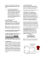
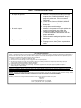
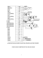
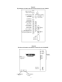
VSP-V-2003A/AHF Issue 8 V-2003A - THREE ZONE PAGE CONTROL UNIT V-2003AHF - THREE ZONE HANDSFREE TALKBACK PAGE CONTROL UNIT INTRODUCTION The V-2003A provides telephone system access to multiple zones (Up to 3) of one way paging plus all call. The V-2003AHF provides telephone system access to multiple zones (Up to 3) of handsfree talkback and/or one-way paging with a one-way all call. SPECIFICATIONS “WARNING: To reduce the risk of fire or electric shock, do not expose this equipment to rain or moisture.” Access Method Electronic Key System (C. O. Line Position) PABX (Loop or Ground Start Trunk) 1A2 Key systems (400 Type Line Card required) 600 Ohm Page Port equipped with contact closure and DTMF dialing capability; Page Port must be bi-directional if using V2003AHF. Dedicated single line telephone(s) “WARNING: Shock Hazard - Do Not Open.” “AVIS: Risque de Choc Electrique ne pas Ouvrir.” “PELIGRO: Corriente Electrica - No Abra.” “CAUTION: To reduce the risk of fire replace only with same type 1A, 125V fuse. 1A, 125V may be replaced by a 0.5A, 250V provided voltage selector is set for 230V.” Features of the V-2003A 3 zones of one-way paging One-way all call Integrated power supply Supplies 20 Valcom power units (-24VDC, 1 Amp) for powering speaker amplifier assemblies Volume Controls supplied for: Background music Tones Night ring/warble tone (Closure or 90VAC ring activated) Time clock/single tone (Closure activated) Options are dip switch programmable per zone (Music and tones) Dial tone (Optional) (#) Button returns dial tone Provides audio for up to 150 Valcom one-way speaker amplifier assemblies per zone “DANGER: Afin de réduire le risque de feu, remplacez le fusible par le même type de fusible à 1A, 125V. On peut utiliser un fusible à 0.5A, 250V pourvu que le sélecteur ďalimentation soit fixé sur 230V. Ne pas ouvrir.” “VORSICHT: Zur verringerung von feuergefahr die sicherung nur mit derselben type 1A, 125V ersetzen. Statt 1A, 125V Kann 0.5A, 250V Benutzt werden, vorausgesetzt, die spannung ist auf 230V eingestellt. Nicht öffnen.” “PELIGRO: Para reducir el peligro de incendio remplazarlo unicamente con un fusible del mismo tipo 1A, 125V. El fusible de 1A, 125V podra ser remplazado por uno de 0.5A, 250V si el selector de voltaje esta puesto en 230V. No abres.” 1 947204 Music Input Level: Output Impedance: -10 to -18dBm 8 Ohms (1 way) 45 Ohms (Talkback) Output level: -10dBm (1 way) 1 Watt (Talkback) DC Output: -24VDC at 1 Amp (V-2003A) -24VDC at 0.5 Amp (V-2003AHF) 115VAC @ 60Hz or 230VAC @ 50Hz operation AC input fused at 1 Amp @ 115VAC or 0.5 Amp @ 230VAC Override page on separate tip/ring temporarily disconnects page in progress and issues an override busy tone to overridden party Normal paging is restored after override Inhibit circuitry (Speaker cancel) UL Listed Nominal Power Requirements Voltage: 115VAC 230VAC Additional Features Supplied by the V-2003AHF 3 zones of handsfree talkback, one-way or mixed paging Dip switch programmable per zone (Music, tones and one-way or talkback) Pre-announce tone (Optional) Repeated alert tone (Optional) Two volume controls for handsfree paging - Page (Phone to speaker) - Receive (Speaker to phone) Supplies 10 Valcom power units (-24VDC, 0.5 Amp) for powering one-way amplified speakers (A reduction of 10 power units from the V-2003A) Battery Backup The V-2003A/V-2003AHF is equipped with a standard 3-prong MOLEX connector to allow connection of a fused output battery backup supply (3 Amp, Valcom VPB-260 or equivalent) in case of AC power failure. Backup time will be a function of system usage. Priority Sequence The V-2003A and V-2003AHF Units are designed with the following priority (1 = highest; 5 = lowest): ___1. Time clock signal ___2. Override page ___3. System page ___4. Night right ___5. Music Weight: V-2003AHF Dimensions: Weight: Use a cord set consisting of a minimum 18 AWG cord and grounding type attachment plug rated a minimum of 15A, 250V. The cord set should have the appropriate safety approvals for the country in which the equipment will be installed and marked HAR. The socket outlet shall be installed near the equipment and shall be easily accessible. 0 to +40 Degrees C 0 to 85% non-condensing OPERATION General Press the line key (Electronic Key System), dial the trunk access code (PABX) or dial the page port access code to access the V-2003A/V-2003AHF; with dedicated single line sets - simple go off hook. The V-2003A/V-2003AHF will return dial tone (If so optioned). Dial desired zone code: 1, 2, 3, or 5, 6, 7 for individual zones (1 through 3 respectively). Dial 4 or 8 for the all call of all zones. Ringback tone (If so optioned) will be heard in the telephone receiver. Make announcement and hang up. The unit will automatically disconnect from page. Ringback tone and repeated alert tones, when optioned, provide an alert tone to the talkback zones on a V-2003AHF. The repeated alert tones will broadcast every 15 seconds when the zone is active in the handsfree mode. 7.10"H x 10.00"W x 3.00"D (18.03cm x 25.40cm x 7.62cm) 4.1 lbs. (1.86 kg) 7.10"H x 10.00"W x 3.00"D (18.03cm x 25.40cm x 7.62cm) 5.6 lbs. (2.54 kg) Nominal Specifications Input Impedance: Input Level: Music Source Impedance: Environment Temperature: Humidity: Physical Description The V-2003A and V-2003AHF are contained in single, gray steel cases, which can be wall or shelf-mounted. V-2003A Dimensions: Current: 1 Amp 0.5 Amp 600 Ohms -10dBm 8 to 600 Ohms 2 Background Music A line level amplified background music source may be connected to the control unit. The background music will cut off only in the zone being paged if the zone is programmed for background music. equipment such as an electronic key system, a PABX or a dedicated single line telephone(s). The V-2003A/V-2003AHF is not intended for direct or indirect connection to the public telephone network or any telephone line providing dial tone. When used with a customer premise telephone system such as a key system or PABX system, these units are interfaced to the system via a fully protected page port or system central office port, which is a fully protected interface device. Also, the host system must be configured to disallow central office trunk conferencing in order to prevent indirect connection to the public network. Night Ring and Single Tones Two methods of night ringing (Electronic Warble Tone) over the paging system is available. ___1. UNA Closure: Activated by a Common Audible, Dry Contact Closure ___2. UNA Ringing: Activated by 90VAC +/- 20% (20/30Hz) ring voltage Clock Tone A single tone over page is provided when a Dry Contact Closure is connected to the Clock Closure Input Terminals (i.e. Time Clock). Electronic Key, 1A2, PABX or Single Line Access When using the V-2003A/V-2003AHF with an electronic key system, 1A2 key system, PABX, or dedicated single line telephones, the following equipment is required: (1) 1 - V-2003A/V-2003AHF Three Zone Paging Unit (2) 1 - C. O. Line Circuit (Electronic Key System), 1A2 line position equipped with 400 type card, Loop or Ground Start Trunk Circuit (PABX), a page port with contact closure and DTMF signaling or one or more dedicated single line telephone(s) (Not a station port or extension number) (3) Valcom Amplified Speaker Assemblies (Quantity and style determined by specific installation; Valcom 45 Ohm Talkback Speakers may also be used with the V-2003AHF) The single tone and warble tone may be dip switch selected on a per zone basis (One dip switch is supplied per zone for tones, so the single tone and warble tone are both selected on or both selected off). Page Port Access When used with page port access, the Page Control Unit may only be used with a 600 Ohm page port equipped with contact closure that will pass DTMF for zone selection. Also, the page port must be capable of passing bi-directional audio for talkback operation (V2003AHF). INSTALLATION Precautionary Designations Mounting The V-2003A/V-2003AHF was designed for wall or table mounting. The intended mounting orientation will render the enclosure lid text legible (See Figure 4). Secure the unit to wall studs or a suitable brace away from heat sources or strong magnetic fields (Motors, fans, power supplies, etc.) with the control and terminal strip accessible (A plywood backboard 2' square and at least1/2" thick attached to wall studs would be considered a suitable brace). Four #10 x 3/4" cross-tip wood screws are included for mounting. Fasten two screws on the mounting surface allowing them to protrude 1/8" to 1/4". Place the chassis of the control unit onto the screwheads at the mounting slots. Position the remaining screws and fasten through the remaining mounting slots. Tighten screws. CAUTION RISK OF ELECTRIC SHOCK DO NOT OPEN CAUTION: To reduce the risk of electric shock, Do not remove cover. No user serviceable parts inside. Refer servicing to qualified service personnel. This symbol indicates that dangerous voltage constituting a risk of electric shock is present within this unit. This symbol indicates that there are important operating and maintenance instructions in the literature accompanying this unit. NOTE: The telephone system referred to in this manual is the customer premise 3 Switch Selectable Options Loop start and ground start access are switch selectable on the V-2003A/V-2003AHF. SW1: Selects the loop or ground start option for system tip and ring. SW5: Selects the loop/ground start option for override tip and ring (See Figure 3 for location). A 12-position dip switch is provided for programming zone capabilities. Figures 1 and 3 indicate the function of each dip switch (i.e., the feature it activates). GROUND START NOTE: When using ground start access, a ground strap must be connected between the telephone system ground and a ground output (+) of the V-2003A/V-2003AHF (See Figure 2). ___3. If a modular cord is used for Tip and Ring connections, connect (J1) RJ11 Tip and Ring to the appropriate C.O. line position of the phone system. NOTE: For one-way paging on a V-2003A, the dip switch for the talkback feature on a one-way zone must be set to "Off: (No zone x talkback). For punchdown block Tip and Ring connections, connect Tip of the telephone system C.O. line position or loop or ground start trunk to the Tip (W/BL) pin and Ring to the (BL/W) of the cross connect block. The V-2003A/V-2003AHF requires a power down reset in order to implement dip switch changes (Unplug AC power from the V-2003A/V-2003AHF for a minimum of 30 seconds then reconnect to effect a dip switch change). Connection of One-Way Amplified Speakers Using twisted pair telephone wire, connect: Zone 1 Speaker Tip, Ring -R/BL, BL/R Zone 1 Speaker -24VDC -R/O Zone 1 Speaker GND -O/R Zone 2 Speaker Tip, Ring -R/G, G/R Zone 2 Speaker -24VDC -R/BR Zone 2 Speaker GND -BR/R Zone 3 Speaker Tip, Ring -R/S, S/R Zone 3 Speaker -24VDC -BK/BL Zone 3 Speaker GND -BL/BK FIGURE 1 SW3 12 11 10 9 8 7 6 5 4 3 Up (OFF) No Zone 3 Music No Zone 3 Tones No Zone 3 Talkback No Zone 2 Music No Zone 2 Tones No Zone 2 Talkback No Zone 1 Music No Zone 1 Tones No Zone 1 Talkback System Dial Tone 2 System Ringback Tone* System Repeated 1 Alert* * Down (ON) Zone 3 Music Zone 3 Tones Zone 3 Talkback Zone 2 Music Zone 2 Tones Zone 2 Talkback Zone 1 Music Zone 1 Tones Zone 1 Talkback No System Dial Tone No System Ringback Tone* No System Repeated Alert* NOTE: The V-2003A provides external power of 20 power units (1 Amp of -24VDC) to operate one-way amplified speakers. Additional power supplies are required for a quantity of speakers using power over the 20 power units. The V-2003AHF supplies external power of 10 power units (1/2 Amp at -24VDC) to operate one-way amplified speakers. Additional power supplies are required for a quantity of speakers using power over the 10 power units. Repeated system alert tone is available only with the V-2003AHF. Ringback tone provides an alert tone over speakers only on handsfree outputs with the V-2003AHF. When using additional power supplies, make certain: 1) The -24VDC outputs are not connected to each other or to the V-2003A/V-2003AHF. 2) Each speaker is connected to only one power source (Talkback speakers do not require power). 3) All power supply grounds are connected directly to a copper cold water pipe earth ground. The use of an electrical ground in place of a direct cold water pipe ground may introduce noise into the paging system. Wiring Instructions for Loop or Ground Start Access A connection block with a 50 pin female amphenol connector must be used to crossconnect speakers and inputs. See Figure 2 for 66 block pinouts. ___1. ___2. Plug 50-pin female Amphenol connector into J2 of the V-2003A/V-2003AHF. Make certain Battery Feed switch (SW2) is ON (In the Down position, See Figure 3). Ascertain SW1 is in proper position. SW1 should be in the UP position for loop start operation or in the DOWN position for ground start operation. 4 Connection of Talkback Speakers (V-2003AHF Only) Using twisted pair telephone wire, connect: Zone 1 Speaker Tip, Ring -BK/G, G/BK Zone 2 Speakers Tip, Ring -BK/BR, BR/BK Zone 3 Speakers Tip, Ring -BK/S, S/BK No more than two (2) 45-Ohm speakers should be connected to any talkback zone. Do not use 8-Ohm speakers. Wiring Instructions for Page Port Access A connection block with a 50 pin female amphenol connector must be used to crossconnect speakers and options. See Figure 2 for 66 block pinouts. V-2003A Volume Adjustments There are two volume controls on the unit for individual adjustment of: When used with page port access, the V-2003A/V-2003AHF may only be used with a 600 Ohm page port that will pass DTMF tones for zone selection and that is equipped with a contact closure. Additionally, the page port must be capable of passing bi-directional audio for talkback operation. ___1. Make certain Battery Feed Switch (SW2) is OFF (In the UP position, See Figure 3). ___2. Plug 50-pin female Amphenol connector into J2 of the V-2003A/V-2003AHF. ___3. Connect Tip and Ring Audio of Page Port to Tip (W/BL) and Ring (BL/W) of the connection block. ___4. Connect wiring from telephone system Page Port Dry Contact Closure to the W/O, O/W pair of the V-2003A/V-2003AHF connection block. Connect cord set to unit via IEC 320 female connector located on one end of cord set to IEC 320 male appliance couple located on the V-2003A/V-2003AHF. For 115VAC use, verify fuse rating of 1 Amp and voltage selector switch displays 115V. For 230VAC use, verify fuse rating of 0.5 Amp and voltage selector switch displays 230V. After all required connections have been made, plug the cord set into appropriate AC wall outlet. Background Music Tones (Warble/single tone) Clockwise adjustment increases volume, counter clockwise decrease volume. During initial set up, adjust individual speaker volume controls to the desired page level first, then adjust volume on page unit to the desired level for music and tones. V-2003AHF Volume Adjustments There are five additional volume controls on the V-2003AHF to control the volume of the handsfree talkback outputs. They are: Page (Adjusts volume of page during all call on handsfree outputs) Speaker to Phone (Adjusts response volume from the speaker; should be turned as low as possible) Phone to Speaker (Adjusts volume of a page from phone) Background Music (Adjusts background music on handsfree outputs) Tones (Adjusts the volume of single and warble tones on handsfree outputs) Power Connections NOTE: This equipment must be installed near an AC power outlet due to the power cord being used as a disconnect device. Refer to Figure 4 for locations of the volume controls. The V-2003A/V-2003AHF is provided with one a NEMA 5-15 cord set for North American use. One-way Speakers may be connected to low level outputs on the V-2003AHF for zones programmed for one-way paging. Refer to Figure 4 for the voltage selector switch and fuse location. Make certain the voltage selector switch is placed at the appropriate rating and that the proper rated fuse is installed. Connections for the V-2003AHF The V-2003AHF is programmable on a per zone basis for one-way or talkback communication. A single talkback zone may have both one-way and talkback speakers. One-way amplified speakers may be connected to the handsfree 5 output of a zone programmed for talkback to augment the page output on that zone. (NOTE: Only talkback speakers are able to receive reply). ___1. ___2. F. Override Connections Telephone System Page Override - (W/S), (S/W). Page override can be activated by a vacant C.O. line position, loop start or ground start trunk, or dedicated single line phone. Using twisted pair telephone wire, connect talkback speakers to the appropriate output (See Figure 3) on the V-2003A/V-2003AHF connection block. Zone 1 speakers connect to the BK-G pair, Zone 2 speakers connect to the BK-BR pair, and Zone 3 speakers connect to the BK-S pair. No more than two (2) 45 Ohm speakers should be connected to any talkback zone. Do not use 8 Ohm speakers. Make certain SW1 is in correct position for loop or ground start mode of operation. TECHNICAL ASSISTANCE When trouble is reported, verify that power is being supplied to the unit and there are no broken connections. Check voltages for proper polarity on the crossconnect block. Table 1 identifies symptoms of some possible problems with solutions. If a spare unit is available, continue to troubleshoot by substituting the spare unit for the suspected defective unit. Adjust volume controls. Optional Connections A. Background Music Connections Connect the low level (-10 to -18dBm, 8 to 600 Ohms) output of music source to (W/GR) and (GR/W) terminals of the cross connect block. Adjust music volume (Page overrides music). Assistance in troubleshooting is available from the factory. When calling, you should have a VOM, a telephone test set, several clip leads available and be calling from the job site. Call (540) 563-2000 and press for Technical Support or visit our website at http://www.valcom.com. NOTE: Failure to use a low level music source could cause music crosstalk on zones not receiving music or damage to the Control Unit. The V-2003A/V-2003AHF is not field repairable. VALCOM equipment contains no user serviceable parts inside. Valcom, Inc. maintains service facilities in Roanoke, VA. Should repairs be necessary, attach a tag indicating company name, address, phone number, contact person and nature of the problem. Send the unit to: Valcom, Inc. Repair and Return Dept. 5614 Hollins Road Roanoke, VA 24019-5056 B. Clock Closure (Single Tone) Connections Time Clock Contact Closure - (V/G), (G/V). Time clock signaling will override page. C. UNA Closure (Warble Tone) Connections Telephone System Night Answer (Contact Closure) - (V/BR), (BR/V). This tone will override music but is overridden by a page. D. UNA Ringing (Warble Tone) Connections 90VAC Night Answer Ringing - (V/S), (S/V). These connections will activate a night ring tone. NOTE: Contact Technical Support (540) 5632000 for more information on Inhibit Option. E. Inhibit Option If a single line telephone is desired for "meet me answer," a single line "A" lead control telephone and a 5.1K resistor is required. This feature is available only if the unit is accessed through a trunk port. The T & R of the telephone connects to the W/BL pair, the "A1" lead connects to GND (BL/BK), the "A" lead had the 5.1K resistor placed in series, and the resistor terminates on inhibit (BR/W). Inhibit is not a feature of override tip and ring access. Calls currently engaged in a "meet me answer" are not disturbed during the override. Connecting Block W/BL T BL/W R BR/W Inhibit BL/BK Ground Tel Sys Trunk Port (Loop Start or Ground Start) T R 5.1K ohm CONNECTIONS FOR INHIBIT OPTION 6 A A1 TABLE 1 - TROUBLESHOOTING CHART SYMPTOMS 1. No output to speakers SOLUTIONS A. Monitor for the presence of audio on the page outputs of the V-2003A/V-2003AHF during a page using a butt set. Refer to connection information. B. Check AC line fuse on V-2003A/V-2003AHF. C. Check dip switch settings and perform a power down reset. D. Verify all other switch settings. 2. No music output A. 3. Programmed feature not functioning A. Check dip switch settings. B. Reprogram zone, then perform a power down reset. Monitor for the presence of music audio on the music input terminals using a Butt Set. B. Check music input connector pins on the V-2003A/V-2003AHF 66 connection block for proper termination. C. Check dip switch settings and perform a power down reset. VALCOM LIMITED WARRANTY Valcom, Inc. warrants its products only to the original purchaser, for its own use, to be free from defects in materials and workmanship under conditions of normal use and service for a period of one year from the date of shipment. This Limited Warranty obligation shall be limited to the replacement, repair or refund of any such defective device within the warranty period, provided that: 1. inspection by Valcom, Inc. indicates the validity of the claim; 2. the defect is not the result of damage, misuse or negligence after the original shipment; 3. the product has not been altered in any way or repaired by others and that factory sealed units are unopened (a service charge plus parts and labor will be applied to units defaced or physically damaged); 4. freight charges for the return of products to Valcom are prepaid; 5. all units 'out of warranty' are subject to a service charge. The service charge will cover minor repairs (major repairs will be subject to additional charges for parts and labor). This Limited Warranty is in lieu of and excludes all other warranties, expressed or implied and in no event shall Valcom, Inc. be liable for any anticipated profits, consequential damages, loss of time or other losses incurred by the buyer in connection with the purchase, operation, maintenance, installation, removal or use of the product. The maximum liability of Valcom under this warranty is limited to the purchase price of the specific Product covered by the warranty. Disclaimer. Except for the Limited Warranty provided herein, the product is provided “as-is” without any warranty of any kind whatsoever including, without limitation, any WARRANTY OF MERCHANTABILITY, FITNESS FOR A PARTICULAR PURPOSE OR NON-INFRINGEMENT. This warranty specifically excludes damage incurred in shipment. In the event a product is received in damaged condition, the carrier should be notified immediately. Claims for such damage should be filed with the carrier involved in accordance with the F.O.B. point. Headquarters: Valcom, Inc. 5614 Hollins Road Roanoke, VA 24019-5056 Phone: (540) 563-2000 FAX: (540) 362-9800 7 Used only with the V-2003AHF System Tip System Ring Page Port Access CC Page Port Access CC Music Input Music Input Not Used Inhibit Override Tip Override Ring Zone 1-Low Level Output Tip Zone 1-Low Level Output Ring -24 Volt Out GND Out Zone 2-Low Level Output Tip Zone 2-Low Level Output Ring -24 Volt Out GND Out Zone 3-Low Level Output Tip Zone 3-Low Level Output Ring -24 Volt Out GND Out Not Used Not Used Zone 1-Handsfree Output Tip Zone 1-Handsfree Output Ring Zone 2-Handsfree Output Tip Zone 2-Handsfree Output Ring Zone 3-Handsfree Output Tip Zone 3-Handsfree Output Ring Not Used Not Used Not Used Not Used Not Used Not Used Not Used Not Used Not Used Not Used Not Used Not Used Not Used Not Used Clock Closure Clock Closure UNA Closure UNA Closure UNA Ringing UNA Ringing 26 1 27 2 28 3 29 4 30 5 31 6 32 7 33 8 34 9 35 10 36 11 37 12 38 13 39 14 40 15 41 16 42 17 43 18 44 19 45 20 46 21 47 22 48 23 49 24 50 25 Loop or GND Start Trunk or Page Port WH/BL BL/WH WH/O O/WH W/GR GR/W W/BR BR/W W/S S/W R/BL BL/R R/O O/R R/G G/R R/BR BR/R R/S S/R BK/BL BL/BK BK/O O/BK BK/G G/BK BK/BR BR/BK BK/S S/BK Y/BL BL/Y Y/O O/Y Y/G G/Y Y/BR BR/Y Y/S S/Y V/BL BL/S V/O O/Y V/G G/V V/BR BR/V V/S S/V Contact Closure (Page Port) Low Level Music Input To Loop or Ground Start Trunk Override TIP RING -24 VDC GND * OPTIONAL LOCAL POWER SUPPLY VALCOM AMPLIFIED SPEAKER TIP RING -24 VDC GND TIP RING -24 VDC GND VALCOM AMPLIFIED SPEAKER Appropriate Telephone System Ground (Ground strap required for good start access only) + -24 VDC 45 Ohm Talkback Speakers (V-2003AHF only) Time Clock Dry Contact Closure Telephone System Common Audible Dry Contact Closure 90 VAC Ringing from an assigned Station Port *POWERSUPPLIES MAY BE ADDEDFORADDITIONAL SPEAKERS ONANY ZONE IF REQUIRED FIGURE 2 66 BLOCK CONNECTIONS FOR THE V-2003A AND V-2003AHF 8 Figure 3 Dip Switches for both units and Volume Controls for the V-2003A SW2 J1 Battery Feed OFF Battery Feed ON Override Tip/Ring SW5 Loop Start Ground Start Dip Switches RJ11 SW1 System Tip/Ring Loop Start Ground Start SW3 Switch Down is "ON" Position and selects option as listed Zone 3 Music Zone 3 Tones Zone 3 Talkback Zone 2 Music Zone 2 Tones Zone 2 Talkback Zone 1 Music Zone 1 Tones Zone 1 Talkback No System Dial Tone No System Alrt/Rngbk Tone No System Repeated Alert R34 TONES R6 MUSIC J2 Male Amphenol Connector Figure 4 Enclosure Orientation and Volume Controls for the V-2003AHF Spkr/ Phone Phone/ Spkr Page Fuse 1A @ 125V-or .5A @ 230V V-2003AHF Tones Music Amphenol Connector Voltage Selector Switch IEC 320 Appliance Coupler 9 Volume Controls


![[P/N: MCB3101] Class I Serial Bluetooth Wireless](http://vs1.manualzilla.com/store/data/005819698_1-328d04723caa8571829b907b8cc9e0c6-150x150.png)