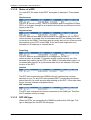
1
Installation, Administration and
Maintenance of the DECToverIP using
SIP solution
Release 1.6
Document ID: depl-0794
Version: 2.0
Aastra
Zeughofstr. 1
10997 Berlin, Germany
June 2008 - All Rights Reserved
No part of this document may be reproduced or transmitted in any form or by any means, electronic or mechanical, including photocopying,
recording, or information storage and retrieval system, for any purpose without the express written permission of Aastra.
Installation, Administration and Maintenance
Table of contents
1
OVERVIEW............................................................................................................................................4
1.1 PURPOSE ......................................................................................................................................4
1.2 DECLARATION OF CONFORMITY ......................................................................................................4
1.3 ABBREVIATIONS AND DEFINITIONS ...................................................................................................4
1.3.1 Abbreviations ..................................................................................................................4
1.3.2 Definitions .......................................................................................................................4
1.4 REFERENCES.................................................................................................................................7
2
INTRODUCTION ...................................................................................................................................8
2.1 ABOUT THE DECTOVERIP USING SIP SOLUTION .............................................................................8
2.2 ABOUT THE ACCESS POINTS (RFPS’) .............................................................................................9
2.3 OPENMOBILITY MANAGER ............................................................................................................12
2.4 IP SIGNALLING AND MEDIA STREAM ...............................................................................................12
2.5 RFP SYNCHRONIZATION ..............................................................................................................16
2.6 RFP CHANNEL CAPACITY..............................................................................................................17
2.7 ABOUT THE PORTABLE PARTS ......................................................................................................18
2.8 SYSTEM CAPACITIES ....................................................................................................................18
3
INSTALLATION AND CONFIGURATION ..........................................................................................19
3.1 OPENMOBILITY START UP .............................................................................................................19
3.1.1 Start up of the RFPs’ ....................................................................................................19
3.1.1.1
3.1.2
3.1.3
3.1.3.1
3.1.3.1.1
3.1.3.1.2
3.1.3.1.3
3.1.3.2
3.1.4
Booter update ........................................................................................................... 24
Each application SW comes with the latest released booter SW. The application SW
will update the booter automatically. Selecting the right DHCP server ..................... 24
3.1.5 RFP LED status ............................................................................................................24
3.1.6 State graph of the start up phases ...............................................................................27
STATIC LOCAL CONFIGURATION OF A RFP .....................................................................................28
CONFIGURING THE OPENMOBILITY MANAGER ...............................................................................33
3.3.1 Service Login procedure...............................................................................................33
3.3.2 System ..........................................................................................................................36
3.3.2.1
3.3.2.1.1
3.3.2.1.2
3.3.2.1.3
3.3.2.2
3.3.2.3
3.3.2.4
3.3.2.5
3.3.3
3.3.4
Creating and Changing RFPs’ .................................................................................. 45
New, change and delete button ................................................................................ 45
Import by configuration files...................................................................................... 46
Capture of RFPs’ ...................................................................................................... 47
States of a RFP......................................................................................................... 48
RFP HW type ............................................................................................................ 48
OMM / RFP SW version check ................................................................................. 49
Configuration of Portable Parts ....................................................................................49
3.3.4.1
3.3.4.1.1
3.3.4.1.2
3.3.4.2
3.3.4.2.1
3.3.4.2.2
3.3.4.3
3.3.5
System settings......................................................................................................... 36
Restarting the OMM ................................................................................................. 38
Encryption................................................................................................................. 38
Regulatory domain ................................................................................................... 39
SIP ............................................................................................................................ 39
User account............................................................................................................. 42
Time zones ............................................................................................................... 43
Backup...................................................................................................................... 44
RFP configuration .........................................................................................................45
3.3.3.1
3.3.3.1.1
3.3.3.1.2
3.3.3.1.3
3.3.3.2
3.3.3.3
3.3.3.4
Aastra
DHCP client .............................................................................................................. 20
DHCP request .......................................................................................................... 20
DHCP offer ............................................................................................................... 22
Retries ...................................................................................................................... 22
TFTP client................................................................................................................ 22
Application ....................................................................................................................22
3.1.4.1
3.1.4.2
3.2
3.3
Booting overview....................................................................................................... 19
Start up of the OpenMobility Manager..........................................................................20
Booter ...........................................................................................................................20
Creating and Changing PPs’..................................................................................... 50
New, change and delete button ................................................................................ 50
Import by configuration files...................................................................................... 51
Subscription .............................................................................................................. 52
Subscription with configured IPEI ............................................................................. 53
Wildcard Subscription............................................................................................... 53
Searching within PP list ............................................................................................ 54
WLAN Configuration (RFP L42 WLAN only) ................................................................54
depl-0794/2.0
Page: 2 (95)
Installation, Administration and Maintenance
3.3.5.1
3.3.5.2
3.3.5.3
3.3.6
Optimizing the WLAN................................................................................................ 57
Securing the WLAN with Radius ............................................................................... 57
Requirements for the WLAN ..................................................................................... 60
System features............................................................................................................60
3.3.6.1
3.3.6.2
Central configuration of LDAP access ...................................................................... 61
Digit treatment........................................................................................................... 62
4
SECURITY...........................................................................................................................................63
4.1 THE SECURITY CONCEPT .............................................................................................................63
4.2 ACCOUNT TYPES ..........................................................................................................................63
4.3 CHANGING ACCOUNT DATA ..........................................................................................................64
4.4 POTENTIAL PITFALLS....................................................................................................................65
5
OMM
5.1
5.2
5.3
5.4
5.5
5.6
RESILIENCY..............................................................................................................................66
HOW OMM RESILIENCY W ORKS...................................................................................................66
INTRODUCTION ............................................................................................................................66
CONFIGURING OMM RESILIENCY .................................................................................................66
FALL OVER SITUATIONS ...............................................................................................................67
FALL OVER FAILURE SITUATIONS ..................................................................................................67
SPECIFIC RESILIENT SITUATIONS ..................................................................................................68
5.6.1 How A Resilient OMM Becomes Active........................................................................68
5.6.2 Handling When Both OMMs’ Are Not Synchronized ....................................................68
5.6.2.1
6
MAINTENANCE ..................................................................................................................................70
6.1 SITE SURVEY MEASUREMENT EQUIPMENT ......................................................................................70
6.2 CHECKING THE AASTRA DECT 142 HANDSET FIRMWARE VERSION ................................................70
6.3 DIAGNOSTIC ................................................................................................................................70
6.3.1 Aastra DECT 142 site survey mode .............................................................................70
6.3.2 Aastra DECT 142 auto call test mode ..........................................................................71
6.3.3 Aastra DECT 142 auto answer test mode ....................................................................71
6.3.4 Syslog ...........................................................................................................................72
6.3.5 ssh user shell................................................................................................................72
6.3.5.1
6.3.5.2
6.3.5.3
6.3.5.4
6.3.6
6.3.7
7
Two DECT Air Interfaces .......................................................................................... 69
Login ......................................................................................................................... 74
Command overview .................................................................................................. 74
RFP console commands........................................................................................... 75
OMM console commands ......................................................................................... 75
Core file captchering.....................................................................................................76
DECT Monitor ...............................................................................................................76
APPENDIX...........................................................................................................................................81
7.1 COMMUNICATIONS REGULATION INFORMATION FOR AASTRA DECT 142 US..................................81
7.2 COMMUNICATIONS REGULATION INFORMATION FOR RFP 32 OR RFP 34 (NA)................................82
7.3 PRE CONFIGURATION FILE RULES .................................................................................................85
7.3.1 PP configuration file (OMM database)..........................................................................86
7.3.1.1
7.3.1.2
7.3.1.3
7.3.2
RFP configuration file/central (OMM database) ...........................................................88
7.3.2.1
7.3.2.2
7.3.2.3
7.3.3
Aastra
Supported Instructions .............................................................................................. 88
Data section fields..................................................................................................... 88
Example.................................................................................................................... 88
RFP configuration file/local (OM Configurator).............................................................90
7.3.3.1
7.3.3.2
7.3.3.3
7.4
Supported Instructions .............................................................................................. 86
Data section fields..................................................................................................... 86
Example.................................................................................................................... 86
Supported Instructions .............................................................................................. 90
Data section fields..................................................................................................... 91
Example.................................................................................................................... 91
PROTOCOLS AND PORTS ..............................................................................................................94
depl-0794/2.0
Page: 3 (95)
Installation, Administration and Maintenance
1
Overview
1.1
Purpose
This document describes the installation, configuration and maintenance of
the DECToverIP using SIP solution.
1.2
Declaration of Conformity
The CE mark on the product certifies its conformity with the technical
guidelines for user safety and electromagnetic compatibility, valid from the
date of issue of the relevant Declaration of Conformity pursuant to European
Directive 99/5/EC. The Declaration of Conformity can be viewed on the
Aastra homepage.
1.3
Abbreviations and definitions
1.3.1
Abbreviations
AC
ADPCM
DHCP
DSP
Authentication Code
Adaptive Differential Pulse Code
Modulation
Digital Enhanced Cordless
Telecommunication
Dynamic Host Configuration Protocol
Digital Signal Processor
FCC
GAP
IPEI
HTTP
OMM
PARK
PP
SNMP
TFTP
RFP
RTCP
RTP
Federal Communications Commission
Generic Access Profile
International Portable Equipment Identity
Hyper Text Transfer Protocol
OpenMobility Manager
Portable Access Rights Key
Portable Part (DECT handset)
Simple Network Management Protocol
Trivial File Transfer Protocol
Radio Fixed Part (Access Point)
Real Time Control Protocol
Real Time Protocol
DECT
1.3.2
Definitions
Aastra DECT 142 Aastra DECT 142 Handset / Aastra 142d
Handset / Aastra In the context of the DECToverIP using SIP solution, an
142d
Aastra DECT 142 Handset, Aastra 142d and Portable
Part (PP) are interchangeable.
In consideration of differences in regulatory requirements
between North America and all other areas of the world
exist two different PP variants which use specific
Aastra
depl-0794/2.0
Page: 4 (95)
Installation, Administration and Maintenance
frequency bands and field strengths:
•
Aastra DECT 142
For use in North America.
•
Aastra 142d
For use in all other areas.
Access Point
Access Point
In the context of the DECToverIP using SIP solution, an
Access Point and a Radio Fixed Part (RFP) are
interchangeable.
Asterisk
Asterisk
Asterisk is a complete Open Source PBX in software. It
runs on Linux, BSD and MacOSX and provides many
features. Asterisk supports voice over IP in many
protocols, and can interoperate with almost all standardsbased telephony equipment.
DECT
Digital Enhanced Cordless Telecommunication
• The standard (ETS 300 175) essentially specifies the
air interface, known as the radio interface. Voice and
data can both be transmitted via this interface.
•
Its technical key characteristics for Europe are:
•
•
•
•
•
Frequency range: approx. 1880 – 1900 MHz
(approximately 20 MHz bandwidth)
10 carrier frequencies (1728 kHz spacing) with 12
time slots each
Doubling the number of time slots (to 24) using the
TDMA process
Net data rate per channel of 32 kbps
(for voice transmission using ADPCM)
Voice coding using the ADPCM method
Its technical key characteristics for North American are:
•
•
•
•
•
Aastra
Frequency range: approx. 1920 – 1930 MHz
(approximately 10 MHz bandwidth)
5 carrier frequencies (1728 kHz spacing) with 12
time slots each)
Doubling the number of time slots (to 24) using the
TDMA process
Net data rate per channel of 32 kbps
(for voice transmission using ADPCM)
Voice coding using the ADPCM method
depl-0794/2.0
Page: 5 (95)
Installation, Administration and Maintenance
GAP
Handover
Generic Access Profile
• GAP is the abbreviation for Generic Access Profile
•
The GAP standard (ETS 300 444) is based on the
same technology as DECT, but is limited to the most
important basic features. This standard was created in
order to allow telephones of different vendors to be
used on any type of DECT system. It thus represents
the smallest common denominator of all manufacturerspecific variants of the DECT standard.
•
An important limitation in the GAP standard is that
external handover is not possible. For this reason
connection handover is used, which is supported by
GAP terminals.
•
The operation of GAP-capable telephones is
comparable to that of analogue terminals. For
example, features can be called up via ‘*’ and ‘#’
procedures.
Handover
A handover is similar to roaming, but occurs during an
ongoing call. A handover normally takes place “in the
background”, without disrupting the call (seamless
handover).
IPEI
International Portable Equipment Identity
• 13-digit identification code for PPs’
• Example: 00019 0592015 3
(the final digit is the checksum).
• The code is represented in decimal form.
• This code is globally unique.
PARK
Portable Access Rights Key
Access code for the Portable Part. This code determines
whether a PP can access a particular DECT system. Used
for unique selection of a dedicated the system from a
handset at enrolment/subscription time. Labelled on the
OpenMobility CD and unique to each SIP-DECT
deployment.
Roaming
Roaming
While in motion, the PP performs ongoing measurements
to determine which RFP is best received. The one that can
be best received is defined as the active RFP. To prevent
the PP from rapidly switching back and forth between two
RFPs’ that have similar signal strength, certain threshold
values are in effect.
Aastra
depl-0794/2.0
Page: 6 (95)
Installation, Administration and Maintenance
1.4
References
/1/ RFC 1350, The TFTP Protocol, Revision 2, July 1992
/2/ RFC 1889, RTP: A Transport Protocol for Real-Time Applications,
January 1996
/3/ RFC 2030, Simple Network Time Protocol (SNTP) Version 4 for IPv4,
IPv6 and OSI, October 1996
/4/ RFC 2131, Dynamic Host Configuration Protocol, March 1997
/5/ RFC 2327, SDP: Session Description Protocol, April 1998
/6/ RFC 2474, Definition of the Differentiated Service Field (DS Field) in the
IPv4 and IPv6 Headers, December 1998
/7/ RFC 2617, HTTP Authentication: Basic and Digest Access
Authentication, June 1999
/8/ RFC 3164, The BSD Sys Log Protocol, August 2001
/9/ RFC 2833, RTP Payload for DTMF Digits, Telephony Tones and
Telephony Signals, May 2000
/10/ RFC 3261, Session Initiation Protocol (SIP), June 2002
/11/ RFC 3264, An Offer/Answer Model with Session Description Protocol
(SDP), June 2002
/12/ RFC 3420, Internet Media Type message/sipfrag, November 2002
/13/ RFC 3515, The Session Initiation Protocol (SIP) Refer method, April
2003
/14/ RFC 3665, The Session Initiation Protocol (SIP) Basic Call Flow
Examples, December 2003
/15/ RFC 3842, A Message Summary and Message Waiting Indication
Event Package for the Session Initiation Protocol (SIP), August 2004
/16/ RFC 3891, The Session Initiation Protocol (SIP) “Replaces” Header,
September 2004
/17/ RFC 3892, The Session Initiation Protocol (SIP) Referred-By
Mechanism, September 2004
Aastra
depl-0794/2.0
Page: 7 (95)
Installation, Administration and Maintenance
2
Introduction
2.1
About the DECToverIP using SIP solution
The DECToverIP using SIP solution comprises the following components:
•
Aastra SIP-DECT Access Points (also known as Radio Fixed Parts
(RFPs’)) being distributed over an IP network and offering DECT wireless
and IP interfaces.
•
A SIP Call Manager/IP PBX/Media Server platform (e.g. Asterisk).
•
Aastra DECT 142 Handsets / Aastra 142d (also known as Portable Parts
(PP))
•
OpenMobility Manager (OMM): Management interface for the
DECToverIP using SIP solution, which runs on one of the Radio Fixed
Parts.
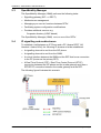
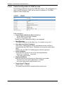
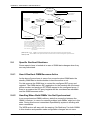
The following figure gives a graphical overview of the architecture of the IP
DECT wireless solution:
The IP PBX/media server/media gateway, OMM and the RFPs’ communicate
through the IP infrastructure. The RFPs’ and the Portable Parts communicate
over the air, where the DECT GAP protocol or DECT GAP with proprietary
enhancements is used.
Aastra
depl-0794/2.0
Page: 8 (95)
Installation, Administration and Maintenance
2.2
About the Access Points (RFPs’)
Aastra DeTeWe provides 3 kind of Access Points:
-
RFP 32
DECT Access Point as indoor model
-
RFP 34
DECT Access Point as outdoor model
-
RFP L42 WLAN
DECT + WLAN Access Point as indoor model
In general the RFP 32 and RFP 34 have the same hardware and software
capabilities. Please be aware of the regulatory differences between North
America and all other areas of the world . These differences lead to different
RFP 32/34 variants which use specific frequency bands and field strengths:
•
•
RFP 32 NA or RFP 34 NA (NA)
-
Frequency Band 1920 to 1930 MHz
-
5 carrier frequencies
-
Transmit Power 20 dBm
RFP L32 IP or RFP L34 IP (EMEA)
-
Frequency Band 1880 to 1900 MHz
-
10 carrier frequencies
-
Transmit Power 24 dBm
The RFP L42 WLAN is only available for the EMEA region.
One RFP within a SIP-DECT installation must be declared to operate as the
OpenMobility Manager (OMM). The RFP acting as the OMM may also act as
a regular RFP as well if it is included into a DECT Cluster.
Aastra
depl-0794/2.0
Page: 9 (95)
Installation, Administration and Maintenance
RFP only mode
Within this mode the RFP converts IP protocol to DECT protocol and then
transmits the traffic to and from the handsets over a DECT time slot. On air
the RFP has 12 available time slots, 8 can have associated DSP resources
for media streams, the remaining 2 time slots are used for control signalling
between RFPs’ and the PPs’, and 2 time slots are reserved for hand-in
purposes.
Groups of RFPs’ can be built which are named clusters. Within a cluster
RFPs’ are synchronized to enable a seamless handover when an user
crosses from one RFP’s zone of coverage to another. For synchronization it
is not necessary for a RFP to communicate directly with all other RFPs’ in the
system. Each RFP only needs to be able to communicate with the next RFP
in the chain. But it is preferable for a RFP to see more than one RFP to
guarantee synchronization in the event that one of the RFPs’ fails.
The 2 control signalling channels are also used to carry bearer signals that
signal the handset to start the handover process. If the radio signal of
another RFP is stronger than that of the current RFP, then the handset starts
the handover process to the RFP that has the stronger signal as the user
moves around the site.
OpenMobility Manager mode
In this mode a RFP functions as a regular RFP. Additionally it is responsible
for SIP signalling between the IP DECT system and the telephony or media
server. Further on it takes over the management part of the IP DECT
solution. You designate a RFP as the OMM by assigning an IP address to
the RFP within the DHCP scope (see chapter 3) or by setting the data via the
OM Configurator (see 3.2). After a RFP is designated as the OMM, it starts
the extra services on board (for example, the web service that supports the
management interface). All RFP’s download the same firmware from a TFTP
server but only one RFP activates the OMM services.
Note: It is possible to deactivate the DECT part of a RFP. If the DECT
interface is deactivated then all resources (CPU and memory) are available
for the OMM.
Aastra
depl-0794/2.0
Page: 10 (95)
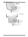
Installation, Administration and Maintenance
RFP 32 NA /
RFP L32 IP
Unused LED
LED green (Application)
LED orange (Application)
LED red (Booter)
Ethernet jack
Power supply in line with Power ov er Ethernet
standard IEEE 802.3af
Power jack (120 V/230 V AC adapter)
RFP L42 WLAN
LED for WLAN
LED green (Application)
LED orange (Application)
LED red (Booter)
Ethernet jack
Power supply in line with Power over Ethernet
standard IEEE 802.3af
Power jack (120 V/230 V AC adapter)
Aastra
depl-0794/2.0
Page: 11 (95)
Installation, Administration and Maintenance
2.3
OpenMobility Manager
The OpenMobility Manager (OMM) performs the following tasks:
•
Signalling gateway (SIP <-> DECT).
•
Media stream management.
•
Managing sync-over-air functions between RFPs’.
•
Facilitating system configuration modifications.
•
Provides additional services e.g.
-
Corporate directory (LDAP based)
The OpenMobility Manager (OMM) runs on one of the RFPs’.
2.4
IP signalling and media stream
To establish a call between an IP Phone and a PP (Aastra DECT 142
Handset / Aastra 142d), the following IP streams must be established:
•
A signalling channel to and from the SIP phone.
•
A signalling channel to and from the OMM.
•
A control interface between the OMM and the RFP that has a connection
to the PP (known as the primary RFP).
•
A Real Time Protocol (RTP) / Real Time Control Protocol (RTCP)
connection between the SIP phone and the media gateway and then a
RTP/RTCP connection between the media gateway and the RFP.
The following figure illustrates this scenario.
Aastra
depl-0794/2.0
Page: 12 (95)
Installation, Administration and Maintenance
To establish a call between two PPs’ the same IP streams must be
established like in the scenario before, except the IP phone is not involved.
The following figure illustrates this scenario.
Aastra
depl-0794/2.0
Page: 13 (95)
Installation, Administration and Maintenance
A call from one PP to another that resides on the same RFP will loop back
within the RFP, if no media gateway is involved. So the call will not pass
through to the Local Area Network (LAN). Although the voice packets will not
impact LAN traffic, signal packets will.
It is also be possible to direct the media stream to connect directly the IP
phone and the RFP, as shown in the following figures.
Aastra
depl-0794/2.0
Page: 14 (95)
Installation, Administration and Maintenance
If the PP user is moving, the PP detects that another RFP has a better signal
strength and, therefore, it starts the handover process. The media stream
from the IP phone cannot move to the secondary RFP, so the primary RFP
uses the LAN to direct the voice to the secondary RFP, as shown in the
following figure.
As the PP user moves into the next RFP zone of coverage, the PP detects
that the RFP has a better signal strength. Again the media stream from the
SIP phone cannot move to the secondary RFP, so the primary RFP uses the
LAN to direct the voice to the new secondary RFP.
Aastra
depl-0794/2.0
Page: 15 (95)
Installation, Administration and Maintenance
2.5
RFP Synchronization
To guarantee a seamless handover if a caller moves from one RFP zone of
coverage to another RFP zone of coverage, an accurate synchronization of
the RFPs’ is necessary.
The RFPs’ are synchronized over the air interface. The first RFP to complete
start-up will transmit a signal on the air for the other RFPs’ to synchronize
from. If a RFP gets in sync then it will transmit a signal on the air and will be
the sync source for the next RFP. Only RFPs’ which can receive a
synchronization signal will become synchronized.
For the RFP to sync to another RFP the signal strength cannot drop below
–70 dBm. You must consider this requirement during the site survey.
As long as an RFP is not in sync, no calls can be established using this RFP.
If a RFP loses the synchronization the RFP does not accept new calls (“busy
bit”). There is a delay of maximum 3 minutes until the active calls on this RFP
are finished. Then it tries to get synchronized again.
An IP DECT installation is more reliable if a RFP can receive the signal from
more than only one RFP, because the other signals are also used for
synchronization.
Aastra
depl-0794/2.0
Page: 16 (95)
Installation, Administration and Maintenance
The sync-over-air solution is very reliable, because all existing redundant
paths are used for synchronization. Thus, hardware tolerances have only
very little influence. No RFP has a key position.
Only unfavourable setups without redundant synchronization paths can
cause problems.
Sometimes RFPs’ do not need to be synchronized, e.g. if they are in different
buildings. These RFPs’ can be put into different clusters. RFPs’ in different
clusters will not be synchronized with each other. Different clusters start up at
the same time independently.
2.6
RFP channel capacity
The RFP has 12 available air time slots:
•
8 slots can have associated DSP resources for media streams.
•
The remaining 4 slots are used for e.g. control signalling between RFPs’
and PPs’, and hand-in purposes.
If all 8 media stream channels are used the RFP announces a “busy bit”. In
that case the PPs’ determine whether another RFP has an appropriate signal
strength. If so, the PP will handover to that RFP. Once the handover has
been completed, the RFP will then lower its “busy bit”.
Whenever the busy state is announced a log entry is made to the system
logs. If the announcement of busy raises in a specific area, a further RFP
should be installed to double the number of media streams available for calls.
Aastra
depl-0794/2.0
Page: 17 (95)
Installation, Administration and Maintenance
2.7
About the Portable Parts
Portable Part (PP) is DECT standard terminology and in the context of the
DECToverIP using SIP solution is interchangeable with Aastra DECT 142
Handset / Aastra 142d.
Please be aware of differences in regulatory requirements between North
America and all other areas of the world. These differences lead to different
PP variants which use specific frequency bands and field strengths:
•
•
Aastra DECT 142 (NA)
-
Frequency Band 1920 to 1930 MHz
-
60 duplex channels
-
100 mW (maximum output per active channel)
-
5 mW (average output per active channel)
Aastra 142d (EMEA)
-
Frequency Band 1880 to 1900 MHz
-
120 duplex channels
-
250 mW (maximum output per active channel)
-
10 mW (average output per active channel)
In addition to the Aastra DECT 142 Handset / Aastra 142d, standard 3rd
party DECT GAP phones may operate on the DECToverIP using SIP
solution. But the functionality may be limited by the characteristics of the 3rd
party DECT phone.
2.8
System capacities
There is only one active OpenMobility Manager (OMM) in the system. The
OMM capacities are:
•
Up to 256 RFPs’ (Access Points) can be controlled.
•
Up to 512 PPs’ (Handsets) are handled.
It is possible to deactivate the DECT part of a RFP. If the DECT interface is
deactivated then the resources (CPU and memory) are available for the
OMM only.
Aastra
depl-0794/2.0
Page: 18 (95)
Installation, Administration and Maintenance
3
Installation and configuration
To establish and maintain an IP DECT installation, a network infrastructure is
assumed, which comprises at least the following components:
•
•
•
•
RFPs’
PPs’
IP PBX/media server (e.g. Asterisk)
TFTP server
The following services should be provided:
•
•
•
•
•
DHCP
SNTP
DNS
LDAP
Syslog daemon
Note: In NA outdoor RFP’s may only be installed with the antennas’ shipped
with the units. No other antennas’ or cabling are permitted. In EMEA the
outdoor RFPs’ are shipped without antennas and you may use the units with
one of the optional antennas’ (separate order no.).
3.1
OpenMobility start up
3.1.1
Start up of the RFPs’
For booting a RFP there must at least a TFTP server on the attached
network to load the OMM/RFP application software.
The essential network settings can be alternatively
• Communicated by a DHCP server at startup time.
• Configured on the RFP with the tool OM Configurator. The settings made
by the OM Configurator will be saved permanently in the internal flash
memory of each OMM/RFP.
The RFP gets the boot image file from a TFTP server. The used TFTP server
needs to support Section 1.3 reference /1/. A used DHCP server needs to
support Section 1.3 reference /4/.
The TFTP and DHCP server need not to reside on the same host.
3.1.1.1 Booting overview
Booting is performed in two steps:
1. Starting the boot process.
2. Starting the application.
Booter
The RFP has only a little standalone application built into the flash. This
software realizes the so called net boot process.
Aastra
depl-0794/2.0
Page: 19 (95)
Installation, Administration and Maintenance
On startup each RFP tries to determine its own IP address and other settings
of the IP interface from the configuration settings in the internal flash
memory. If no settings are available or these settings are disabled, the RFP
tries to determine these settings via DHCP.
The RFP gets the application image file from the TFTP server.
Application
After starting the application image the RFP checks the local network settings
in its internal flash memory once again. If no settings are available or if they
are disabled it starts a DHCP client to determine the IP address of the OMM
and other startup settings.
3.1.2
Start up of the OpenMobility Manager
There is no difference in booting that RFP, which is chosen to be running in
OMM mode from those which are in the RFP only mode.
The decision is driven by the OMM IP address, which is read
• within the local network settings, if active.
• via DHCP request.
The RFP which has the same IP address as the dedicated OMM IP address,
will be the RFP which the OMM software runs on.
3.1.3
Booter
3.1.3.1 DHCP client
Within the initial boot process the DHCP client supports the following
parameters:
•
•
•
•
•
•
IP address
Net mask
Gateway
Boot file name
TFTP server
Public option 224: “OpenMobility”
mandatory
mandatory
mandatory
mandatory
mandatory
mandatory
3.1.3.1.1 DHCP request
3.1.3.1.1.1 Vendor class identifier (code 60)
The DHCP client sends the vendor class identifier “OpenMobility”.
3.1.3.1.1.2 Parameter request list (code 55)
The DHCP client in the booter requests the following options in the
parameter request list:
• Subnet mask option (code 1)
• Router option (code 3)
Aastra
depl-0794/2.0
Page: 20 (95)
Installation, Administration and Maintenance
• Public option 224 (code 224)
• Public option 225 (code 225)
• Public option 226 (code 226)
Aastra
depl-0794/2.0
Page: 21 (95)
Installation, Administration and Maintenance
3.1.3.1.2 DHCP offer
The DHCP client selects the DHCP server according to the following rules:
•
The public options (code 224) has a value equal to the string
“OpenMobility”.
or
•
the file field in the DHCP message has a sub string equal to “ip_rfp.cnt”.
If none of the two rules above match the DHCP offer is ignored.
Information retrieved from the DHCP offer:
• The IP address to use is taken from the yiaddr field in the DHCP
message.
• The IP netmask is taken from the subnet mask option (code 1).
• The default gateway is taken from the router option (code 3).
• The TFTP server IP address is taken from the siaddr field in the DHCP
message.
• The boot image filename is taken from the file field in the DHCP message,
if this field is empty the default filename “iprfp.bin” is used.
3.1.3.1.3 Retries
If the DHCP client does not get an appropriate DHCP offer a new DHCP
request is send after 1 second. After 3 DHCP requests are sent the DHCP
client will sleep for 60 seconds.
During this time the booter will accept a local configuration with the OM
Configurator (OMC).
This cycle will repeat every 3 minutes until either ALL the required DHCP
options are provided or the system is manually configured using the OM
Configurator tool.
3.1.3.2 TFTP client
The TFTP client will download the application image from the TFTP server.
Both TFTP server and the name of the application image are supplied via the
DHCP client. The application image is checksum protected.
3.1.4
Application
After successfully downloading and starting the application the RFP will
determine the IP address of the OMM from DHCP.
The DHCP client is capable of receiving broadcast and unicast DHCP
replies. Therefore the flags field is 0x0000.
The DHCP request contains the well-known magic cookie (0x63825363)
and the end option (0xFF).
Aastra
depl-0794/2.0
Page: 22 (95)
Installation, Administration and Maintenance
The following parameters will be supported within this step:
Option / Field
Meaning
Mandatory
yiaddr
IP address of the IP-RFP
yes
siaddr
Parameter named Boot Server Host Name with
value as the IP address of the TFTP server
yes
file
Parameter named Bootfile Name with value of
the path (optional) and name of the application
image. For example omm_ffsip.tftp.
yes
code 1
Subnet mask
yes
code 3
Default Gateway
yes
code 6
Domain Name Server
No
code 15
Domain Name
No
code 42
IP address of a NTP server
No
code 43
Vendor Specific Options
yes
public option 224
Parameter named magic_str must be set to value
"OpenMobility".
yes
The Vendor Specific Options consist of:
Vendor Specific
Meaning
Option
option 10
ommip1: Used to select the IP-RFP who
should reside the Open Mobility
Manager (OMM)
option 14
option 15
option 17
option 18
option 19
syslogip: IP address of a Syslog
Daemon
syslogport: Port of a Syslog Daemon
Country: Used to select the country in
which the OMM resides. This enables
country specific tones (busy tone, dial
tone, ...)
ntpservname: Name of a NTP Server
ommip2: Used to select a secondary IPRFP who should reside the resilient or
standby Open Mobility Manager (OMM).
This option must be given if the OMM
Resiliency feature should be used (see
chapter 5).
Length
Mandatory
4
yes
4
No
2
2
No
No
x
4
No
No
An example of the minimal contents for the Option 43 parameter value would be:
0a 04 C0 A8 00 01 where C0 A8 00 01 represents 192.168.0.1 for the OMM IP.
The option 43 contain a string of codes in hex the format is “option number” “length” “value”
in this example
0a = option 10 (ommip1)
04 = following value is 4 blocks long
C0 A8 00 01 = 192.168.0.1
If there is more than one option, add the next option at the end of the previous one.
Depending of the DHCP server you need to end the option 43 with FF.
Aastra
depl-0794/2.0
Page: 23 (95)
Installation, Administration and Maintenance
Tones for the following countries are supported:
country
code
1
2
3
4
6
7
8
9
10
11
12
13
14
15
16
17
18
19
20
21
22
24
25
100
101
102
country
Germany
Great Britain
Suisse
Spain
Italy
Russia
Belgium
Netherlands
Czech
Austria
Denmark
Slovakia
Finland
Hungary
Poland
Belarus
Estonia
Latvia
Lithuania
Ukraine
Norway
Sweden
Taiwan
North America
France
Australia
3.1.4.1 Booter update
3.1.4.2 Each application SW comes with the latest released booter
SW. The application SW will update the booter automatically.
Selecting the right DHCP server
The DHCP client requests its own IP address using code 50. The DHCP
client will select the DHCP server that offers the currently used IP address.
Additionally the mandatory options must be offered otherwise the DHCP offer
is ignored by the DHCP client.
If no matching reply was received the DHCP client resends the request 2
times after 1 second. Then the DHCP client will wait for 1 minute before
resending 3 requests again.
If the DHCP client cannot accept an DHCP offer within 3 minutes the RFP is
rebooted.
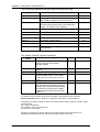
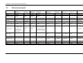
3.1.5
RFP LED status
The following diagrams show the LED status of a RFP according to the
different states during start up.
The RFP L32 IP has three separate LEDs’ for red, orange and green to show
the different states during start up.
Aastra
depl-0794/2.0
Page: 24 (95)
Installation, Administration and Maintenance
RFP 32 NA /
RFP L32 IP
Unused LED
LED green (Application)
LED orange (Application)
LED red (Booter)
Ethernet jack
Power supply in line with Power over Ethernet
standard IEEE 802.3af
Power jack (120 V/230 V AC adapter)
State
LED state
Remarks
Booter (Start up)
Red on
Waiting for link up
Booter DHCP
Red flashing 0.5 Hz
Launching a DHCP request and
waiting for an DHCP offer
Booter (TFTP)
Red flashing 2.5 Hz
Downloading the application
image
Application (DHCP)
Orange on
Launching DHCP request and
waiting for DHCP reply
Application (init)
Green flashing 0.5 Hz
RFP is initializing its internal
components
Application (init)
Green flashing 1 Hz
RFP tries to connect to the
OMM
Application (init)
Green flashing (2 sec on, 0.5
sec off)
The DECT part of the RFP
does not work (either not
configured or not synchronized
with other RFPs’)
Application (init)
Green
RFP is up and running
The RFP L42 WLAN has an additional LED describing the WLAN status:
1
State
WLAN LED state
WLAN module not found
Red on
WLAN deactivated because OMM is running
off
WLAN deactivated per configuration
off
WLAN deactivated because 10 Mbps1
Green flashing 1 Hz
WLAN up and running
Green on
The RFP L42 WLAN must connect to a 100BaseT Ethernet for WLAN service.
Aastra
depl-0794/2.0
Page: 25 (95)
Installation, Administration and Maintenance
RFP L42 WLAN
LED for WLAN
LED green (Application)
LED orange (Application)
LED red (Booter)
Ethernet jack
Power supply in line with Power over Ethernet
standard IEEE 802.3af
Power jack (120 V/230 V AC adapter)
Aastra
depl-0794/2.0
Page: 26 (95)
Installation, Administration and Maintenance
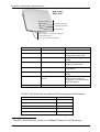
3.1.6
State graph of the start up phases
LED RED ON
Start-up
wait for link up
BOOTER
LED RED ON
Wait for 6 seconds; listen
for local configuration
yes
Local
configuration
LED red
flashing 0,25 Hz
no
LED red
flashing 0,5 Hz
retry
DHCP no answer / offer not o.k.
DHCP
Wait for 60 seconds; listen
for local configuration
wait for reply
LED red
flashing 2,5 Hz
TFTP
TFTP failed
File download
Kernel
Local
configuration
Listen for local configuration in every state
no
yes
LED orange
LED orange
DHCP
Local conf. Start-up
wait for reply
LED green
flashing (0,5 Hz)
Application
Init failed
Init
LED green
flashing 1 Hz
Application
Connect to OMM
LED green
flashing 2 seconds
on / 50ms off
DHCP no answer; offer not o.k.
(try 3 minutes)
Application
Connection attempt to OMM failed
Failure, i.e. connection to OMM lost
Synchronize DECT
LED green
Application
Failure, i.e. connection to OMM lost
Up & running
*
Change of the local configuration
Aastra
depl-0794/2.0
Page: 27 (95)
Installation, Administration and Maintenance
3.2
Static local configuration of a RFP
As an alternative to DHCP configuration, the RFPs’/OMM may be individually
statically configured using the OM Configurator tool.
The OM Configurator requires the Java Runtime Environment version 1.6 or
higher.
The settings, which are configured on the RFP with the tool OM Configurator,
will be saved permanently in the internal flash memory of an RFP.
The parameters configurable via the OM Configurator comply with the DHCP
option, please see section 3.1.4 for details.
If a local static configuration has been done, DHCP is not used anymore.
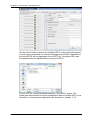
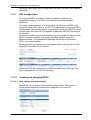
The following figure shows the OM Configurator.
On
system with multiple Ethernet adapters select the interface to use for the
configuration of the RFP’s.To configure a RFP, at least the MAC address and
all mandatory options (see table below) have to be set. The MAC address
must be entered in a format such as xx-xx-xx-xx-xx-xx.
If the RFP has already an IP address enter this address in the IP address
field. In this case you can reach the RFP from outside the local LAN
segment. Optional.
To set additional parameters, press the “Add parameter” button and choose
the desired parameter.
Aastra
depl-0794/2.0
Page: 28 (95)
Installation, Administration and Maintenance
IMPORTANT: Select the “yes” checkbox for the RFP to “Use local
configuration” otherwise DHCP will be used.
Press the “Send configuration” button to transmit the parameters to an RFP.
Boot Parameters (comply with DCHP options)
Parameter
Type
Meaning
Use local configuration mandatory The parameter defines whether the local configuration settings
should be used when booting or not.
IP Address
mandatory IP address of the RFP
Net mask
mandatory Subnet mask of the IP network
TFTP Server Address
mandatory IP address of the TFTP server
TFTP File Name
mandatory The boot file be read from the TFTP server at startup.
OMM IP Address
mandatory IP address of the OpenMobility Manager
Router addresses
optional
IP address of Default gateway
DNS Addresses
optional
IP address of DNS server
DNS Domain
optional
Domain name of the network
Broadcast Address
optional
The broadcast address for that network
2nd OMM IP Address
optional
IP address of the resilient/standby OMM
Country
optional
Defines the country in which the OMM resides to handle country
specific call progress tones.
NTP Server Address
optional
IP address of a NTP Server
NTP Server Name
optional
Name of a NTP Server
VLAN ID
optional
VLAN identifier
Syslog IP Address
optional
Destination IP address for the syslog
Syslog Port
optional
Destination port for the syslog
The configuration can only be set after powering up or at the retry phase
(LED flashing 0,25 Hz) or in kernel mode, please see section 3.1 for details.
The configurator tool waits 2 seconds and retries transmitting the data 3
times.
Aastra
depl-0794/2.0
Page: 29 (95)
Installation, Administration and Maintenance
If you want to read the configuration parameters from an RFP set the MAC
address and the IP address additionally and press the “List configuration”
button. All parameters will be listed in the OM Configurator tool.
Press the “Reset configuration" button to clean all input fields and additional
parameters.
Since the OpenMobility version 1.5, login data can be used to prevent
against unauthorized configuration changes. If authorization is used, mark
the ‘Login’ check box and enter the user name and the password into the
fields ‘User’ and ‘Password’. This OM Configurator is backward compatible to
previous OpenMobility versions without login support.
A forgotten password couldn’t be recovered but deleted using the ‘Factory
defaults’ button. Send the displayed cookie to the OpenMobility manufacturer
support. After receiving the password reset key from the support, enter it into
the ‘Enter reset key’ dialog. This will delete the complete local configurations
from the internal flash memory of the RFP, too!
WARNING: With the password reset all local configurations inclusively
possible existing OpenMobility configurations will be deleted.
A RFP outside the local LAN segment could also work as proxy. Mark the ‘as
proxy’ check box to enable this functionality. Then the MAC address will be
used to address a RFP in the LAN segment of the proxy RFP. Scanning for
available RFPs’ and configuration of multiple RFPs’ via a configuration file
could be used also with the proxy mechanism.
Aastra
depl-0794/2.0
Page: 30 (95)
Installation, Administration and Maintenance
Use the ‘Scan’ button to search for available RFPs’ in the local LAN segment
or via the proxy mechanism in outside LAN segments. All MAC addresses of
the found RFPs’ will be displayed in the left RFP list. The status LED’s and
the update button are disabled after scanning for RFPs’.
The list of RFPs’ could be saved by using the ‘Save RFP’s’ button. This
enables an administrator to edit the configuration data of multiple RFPs’ via a
text editor or a spread sheet application like described in chapter 7.3.3.
Aastra
depl-0794/2.0
Page: 31 (95)
Installation, Administration and Maintenance
The prepared configuration file could be loaded using the ‘Load config.’
button. Log files with status information about parsing and executing the
configuration file and data are stored into the same directory.
Use the ‘Run config’s’ button to start the iterative configuration of multiple
RFPs’ using the prepared and loaded configuration file. The LED’s will
display whether the configuration has succeeded or failed. See the log file
content for further information. If the configuration has failed for a RFP the
configuration could be repeated using the update button beside the LED’s.
Note that the login and proxy data will be used for the whole configuration
file!
Aastra
depl-0794/2.0
Page: 32 (95)
Installation, Administration and Maintenance
3.3
Configuring the OpenMobility Manager
The OMM runs on a designated RFP within a SIP-DECT deployment. The
OMM is designated via DHCP options or statically declared via the OM
Configurator tool. All other RFPs’ in the deployment are configured to point
back to the OMM in the deployment.
The OMM can be configured via HTTP/HTTPS. The OMM acts as a
HTTP/HTTPS server. The HTTP server binds to port 80 and HTTPS binds to
port 443 by default. The configuration data will be read from the internal flash
memory.
The configuration is stored in a human readable ASCII file. Changing the
configuration file outside the OMM is not permitted.
The configuration file can be downloaded and uploaded via the web
interface.
The service access is restricted to one active session at a time and is
password protected.
The browser used for service access has to be at least Microsoft Internet
Explorer 6.0 or Mozilla Firefox 1.5 and must have frame support, JavaScript
and cookies enabled.
3.3.1
Service Login procedure
The OMM allows only one user at a time to configure the system. A user
must authenticate with a user name and a password. Both strings are
checked case sensitive.
With initial installation or after removing the configuration file the
OpenMobility service is accessible via a default build-in user account with
user “omm” and password “omm”.
With the first login into a new OpenMobility version the user have to accept
the End User Licence Agreement (EULA).
Aastra
depl-0794/2.0
Page: 33 (95)
Installation, Administration and Maintenance
If the default build-in user account is active the administrator have to change
the password of the “Full access” and “root” account. The meaning of the
different account types is described in chapter 4.2 and 4.3.
Aastra
depl-0794/2.0
Page: 34 (95)
Installation, Administration and Maintenance
After login there are the following options available:
Configuration of general SIP-DECT system parameters.
Administration of the attached RFPs’.
Administration of the PPs’.
Configuration of WLAN parameters
Administration of System features like digit treatment and directory
Displaying the End User Licence Agreement (EULA)
If no user action takes place the OMM logs out the user after 5 minutes.
To logout from the system click the “Logout” button.
Aastra
depl-0794/2.0
Page: 35 (95)
Installation, Administration and Maintenance
Note: If the browser is closed without logging out first the service access will
be blocked for other clients for 5 minutes.
3.3.2
System
3.3.2.1 System settings
The system settings cover global settings for the OpenMobility Manager like:
•
System Name
•
Remote Access
Switches on/off the ssh access to all RFPs of the DECT system.
•
DECT Authentication Code.
The authentication code is used during initial PP subscription as a
security option (see chapter 3.3.4). A code entered here provide a
default DECT Authentication Code for each new created PP (see
chapter 3.3.4.1). It is optional.
•
PARK
Each DECT network requires a unique PARK key. Enter the PARK
key as labelled on the OpenMobility CD. It is mandatory.
•
Encryption as described in the chapter 3.3.2.1.2
•
Regulatory Domain as described in the chapter 3.3.2.1.3
•
DECT Monitor
For monitoring the DECT system behaviour of the OpenMobility
Manager a separate application will be delivered. This tool needs an
access to the OpenMobility Manager which is disabled by default and
can be enabled on the system page. Because of security, the DECT
monitor flag is not stored permanently in the internal flash memory of
the OMM/RFP. After a reset the DECT monitor flag is ever disabled.
•
Aastra
ToS and TTL Parameters
depl-0794/2.0
Page: 36 (95)
Installation, Administration and Maintenance
To allow the prioritisation of Voice Packets and/or Signalling Packets
(SIP) inside the used network the IP parameter ToS (Type of Service)
should be configured here.
•
Syslog Parameters
The OpenMobility Manager and the RFPs’ are capable of propagating
syslog messages. This feature together with the IP address of a host
collecting these messages can be configured.
•
Date and Time Parameters
If SNTP is not used, date and time can be configured at the OMM.
This has to be done to provide date and time to the DECT 142
Handset / Aastra 142d.
The rules for a time zone, which is shown on this web page, can be
configured at the Time zones section of the web service (see chapter
3.3.2.4).
Please note, that in the case that SNTP is not used, the date and time
has to be configured after every restart of the RFP, where the
OpenMobility Manager is running.
The date and time will be provided by the OpenMobility Manager to
the DECT 142 Handset / Aastra 142d if the handset initiates a DECT
location registration. This will be done in the following cases:
Aastra
•
Subscribing at the OMM
•
Entering the network again after the DECT signal was lost
•
Power on
•
Silent charging feature is active at the phone and the phone is
taken out of the charger
•
After a specific time to update date and time
depl-0794/2.0
Page: 37 (95)
Installation, Administration and Maintenance
Please,
enter the
PARK key as
labelled on the
OpenMobility
CD
3.3.2.1.1 Restarting the OMM
To restart the OMM select “System Settings” from the navigation tree and
then select ‘Restart’. There is also the option to reset the configuration data.
A reset web page is loaded then displaying a progress bar and the login web
page is loaded automatically if the OMM is reachable again.
3.3.2.1.2 Encryption
Encryption is only available on RFP 32/34/42 products. Therefore it can only
be enabled on the “System Settings” web page if there are no other Aastra
RFP variants connected to the OMM.
Aastra
depl-0794/2.0
Page: 38 (95)
Installation, Administration and Maintenance
If encryption is enabled and another RFP variant connects to the OMM, its
DECT air interface will not be activated.
Note: The PPs’ have to support DECT encryption which is not a mandatory
feature.
3.3.2.1.3 Regulatory domain
To define where the IP DECT is used the parameter regulatory domain has
to be configured. Existing installations are updated to the default value
“EMEA (ETSI)”.
To setup a North American FCC compliant installation the value has to be set
to “US (FCC/CI)”
In a North American US (FCC/CI) deployment, ETSI compliant RFPs’ are
made inactive and can not be activated if the regulatory domain is set to “US
(FCC/CI)”. Vice-versa is also true.
Only US (FCC/CI) DECT 142 handsets may be connected to RFPs’/OMM
designed for the US market and configured to use the US (FCC/CI)
regulatory domain.
3.3.2.2 SIP
The SIP settings cover all global settings matching the SIP signalling and the
RTP voice streams.
Aastra
•
Proxy Server
IP address or name of the SIP proxy server. If a hostname and
domain are used for the proxy server parameter, ensure that a
DNS server and domain are specified for your SIP-DECT
system via DHCP or the OM Configurator tool.
•
Proxy Port
SIP proxy server’s port number. Default is 5060. To enable
DNS SRV support for proxy lookups, use a value of 0 for the
proxy port.
•
Registrar Server
IP address or name of the SIP registrar. Enables the PPs’ to be
registered with a Registrar. If a hostname and domain are used
for the proxy server parameter, ensure that a DNS server and
domain are specified for your SIP-DECT system via DHCP or
the OM Configurator tool.
•
Registrar Port
SIP Registrar’s port number. Default is 5060. To enable DNS
SRV support for registrar lookups, use a value of 0 for the
registrar port.
•
Registration Period
The requested registration period, in seconds from the registrar.
Default is 3600.
•
Outbound Proxy
Address of the outbound proxy server. All SIP messages
originating from the OMM are sent to this server. For example, if
depl-0794/2.0
Page: 39 (95)
Installation, Administration and Maintenance
you have a Session Border Controller in your network, then you
would normally set its address here. Optional.
Aastra
•
Outbound Proxy Port
The proxy port on the proxy server to which the OMM sends all
SIP messages. Optional.
•
Explicit MWI Subscription
Some Media Server such as the Asterisk support Message
Waiting Indication (MWI) based on /15/. A MWI icon will be
presented on an Aastra DECT 142 Handset / Aastra 142d if the
user has received a voice message on his voice box which is
supported by the Media Server. If Explicit MWI Subscription is
enabled the OMM sends explicit for each PP a MWI
Subscription message to the Proxy or Outbound Proxy Server.
•
User agent info
If enabled the OMM send out information about his version
inside the SIP headers User-Agent/Server.
•
Send dial terminator
If enabled the OMM doesn’t use the ‘#’ character to detect the
completeness of dial input from a user. Instead the OMM waits 4
seconds for additional input after the user has pressed a dial
digit. If enabled the ‘#’ character can be part of dial information.
•
Registration retry timer
Specifies the time, in seconds, that the OMM waits between
registration attempts when the registration is rejected by the
registrar.
•
Transaction timer
The amount of time in milliseconds that the OMM allows a
callserver (proxy/registrar) to respond to SIP messages that it
sends. If the OMM does not receive a response in the amount of
time designated for this parameter, the OMM assumes the
message as timed out. In this case the callserver is recorded to
the blacklist. Valid values are 4000 to 64000. Default is 4000.
•
Blacklist time out
The amount of time in minutes a unreachable callserver stay in
the blacklist. Valid values are 0 to 1440. Default is 5.
•
RTP Port Base
Each RFP needs a continuous port area of 68 UDP ports for
RTP voice streaming. The RTP Port Base is the start port
number of that area. Default is 16320.
•
Preferred Codec 1 – 5
Specifies a customized codec preference list which allows you
to use the preferred Codecs. The Codec 1 has the highest and
Codec 5 the lowest priority.
•
Silence Suppression
Used to configure whether Silence Suppression is preferred or
not.
depl-0794/2.0
Page: 40 (95)
Installation, Administration and Maintenance
•
DTMF Out-of-Band
Used to configure whether DTMF Out-of-Band is preferred or
not.
.
•
DTMF Method
The OMM supports the following DTMF Out-of-Band methods:
o RFC 2833
Transmit DTMF as RTP events according to RFC 2833
(/9/) after the payload type negotiation via SIP/SDP. If the
payload type is not negotiated, “inband” will be used
automatically.
o INFO
The SIP INFO method is used to transmit DTMF tones as
telephone events (application/dftmf-relay). This setting
should be used if RFC 2833 is not supported.
o BOTH
DTMF telephones events are send according to RFC
2833 and as well as SIP INFO method.
Please Note: Possibly, the other party recognises events
twice.
•
Aastra
DTMF Payload Type
If Out-of-Band is enabled the Payload Type specify the payload
type which is used for sending DTMF events based on Section
1.3 reference /9/.
depl-0794/2.0
Page: 41 (95)
Installation, Administration and Maintenance
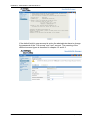
3.3.2.3 User account
After initial installation or after removing the configuration file the
OpenMobility service is accessible via a build-in user account with user “omm”
and password “omm”. These settings which are case sensitive can be
changed on the “User Account” web page.
The meaning of the different account types is described in chapter 4.2 and
4.3.
Aastra
depl-0794/2.0
Page: 42 (95)
Installation, Administration and Maintenance
3.3.2.4 Time zones
A time and date resynchronization of the Aastra DECT 142 / Aastra 142d
devices is described in chapter 3.3.2.1.
In the time zone section the OpenMobility Manager provides all available
time zones. They are set with their known daylight savings time rules
adjusted to the Universal Coordinated Time (UTC) per default. The difference
to the UTC time is shown in the “UTC Difference” column. In case of a
configured daylight savings time rule this is also marked for each time zone.
There is a possibility to change the time zone rules for maximal five time
zones. Changed rules are marked with a bold time zone name in the table.
The changes are saved in the configuration file and are restored after each
OpenMobility Manager startup. The “Default” button sets all time zones back
to the default values and deletes the changed time zone rules in the
configuration file.
With the “Configure Time Zone” dialog the standard time and the daylight
savings time (DST) of a time zone can be changed. If the time zone has no
DST only the UTC difference can be configured. For the DST both points of
time (begin of standard time and begin of daylight savings time) have to be
specified exactly. Therefore a certain day in the month or a certain week day
in a month can be used. See the following screen shots as an example:
Aastra
depl-0794/2.0
Page: 43 (95)
Installation, Administration and Maintenance
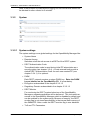
3.3.2.5 Backup
The web service interface allows to save a copy of the current configuration
on the local host (host where the browser application is executed) as well as
to restore an older configuration.
Aastra
depl-0794/2.0
Page: 44 (95)
Installation, Administration and Maintenance
Restoring a previously saved configuration will lead to a reset of the OMM to
take effect.
3.3.3
RFP configuration
All configured RFPs’ are listed in tables grouped to clusters by its
topographic relations. The RFPs’ are sorted by their ethernet (MAC)
addresses.
To ensure correct handover of a PP during a call, all involved RFPs’ must
deliver the same clock signal to the PP. This is achieved by having the RFPs’
synchronized. The synchronization is achieved by placing the RFPs’ so close
to each other, that every RFP recognizes at least one other RFP through its
air interface.
There are conditions where synchronization is not possible, for instance with
RFPs’ at remote locations. In this case the RFPs’ shall be grouped in
different clusters. The OpenMobility Manager will not try to synchronize
RFPs’ over cluster borders.
All used clusters are displayed in the navigation bar on the left side and the
OMM RFP is marked with a bold font.
When the RFPs’ are connecting the OMM they submit their HW type. This
type is displayed on the RFP list web page.
3.3.3.1 Creating and Changing RFPs’
3.3.3.1.1 New, change and delete button
New RFPs’ can be added to the system by pressing the “New” button. A
popup window appears providing the configuration of a new RFP.
Aastra
depl-0794/2.0
Page: 45 (95)
Installation, Administration and Maintenance
Each RFP is identified by its MAC address (6 bytes hex format, colon
separated). The ethernet address is unique and can be found on the back of
the chassis.
For easier administration each RFP can be associated with a location string.
The location string can hold up to 20 characters.
The DECT functionality for each RFP can be switched on/off. If DECT is
active the RFP can be assigned to a cluster.
The WLAN section is only destined for RFP L42 WLAN.
In the ‘WLAN settings’ section of the page can be select Profile, Antenna
Diversity, Antenna, Output Power Level and Channel. Antenna Diversity
should generally be activated (i.e. ticked) so that the AP can automatically
select the antenna with the best transmission and reception characteristics.
Important note:
A RFP which is configured as OMM cannot simultaneously operate as a
WLAN Access Point.
For details about WLAN configurations please see chapter 3.3.5.
The same popup window could be opened for an existing RFP by pressing
the tool icon of the appropriate RFP.
A RFP could be deleted by pressing the trash can icon . A similar popup
window asks for confirmation showing the current configuration of this RFP.
3.3.3.1.2 Import by configuration files
A set of RFPs’ can also be configured in a semiautomatic manner by import
of a configuration file. Please press the “Import” button to navigate to the
referring sub menu:
Select your configuration file and press the “Import” button (see Appendix
7.3.2 to get information about file layout ). A parsing protocol can be read, if
you press the referring “Logfile” button. All successfully imported data
records are presented in a list:
Aastra
depl-0794/2.0
Page: 46 (95)
Installation, Administration and Maintenance
To add the RFPs’ to the OMM database, select them by the radio button and
press “Add”.
All successfully stored records are marked green in the column called
“Added” (failed records are get a red star, error hints can be read in the
referring logfile or in a Syslog trace).
3.3.3.1.3 Capture of RFPs’
RFPs’, which are assigned to the OMM by DHCP options or OM Configurator
settings, may plug to the system. Please press the referring “Start” button on
the RFP list web page.
After a while the list page is filled by the MAC addresses of those RFPs’
which tried to register to the OMM.
Please note that these entries are not really stored (they are lost after reset).
By pressing the tool icon of the appropriate RFP, you can add further data
and store the RFP.
Aastra
depl-0794/2.0
Page: 47 (95)
Installation, Administration and Maintenance
3.3.3.2 States of a RFP
For each RFP the state of the DECT subsystem is displayed. These states
are:
Synchronous
The RFP is up and running. The RFP recognizes and is recognized by other
RFPs’ in its cluster through its air interface and delivers a synchronous clock
signal to the PPs’.
Asynchronous
The RFP has not been able to synchronize to its neighbours yet. No DECT
communication is possible. But nevertheless the RFP has already been able
to connect to the OMM. This phase should usually last only for a few seconds
after starting up the RFP or the OMM. If this state lasts longer this is an
indication for a hardware or network failure.
Searching
The RFP has lost synchronization to its neighbours. No DECT
communication is possible. This phase should usually last only for a few
seconds after starting up the RFP or the OMM. If this state lasts longer or is
re-entered after being in a synchronous state this is an indication for a bad
location of the RFP.
Inactive
The RFP has connected to the OMM but the air interface has not been
switched on yet. For any RFP with activated DECT functionality this phase
should last only for a few seconds after starting up the RFP. If this state lasts
longer this may indicate a hardware failure.
Not connected
The RFP was configured but has not connected to the OMM yet. Therefore
the IP address column is empty.
3.3.3.3 RFP HW type
When the RFPs’ are connecting the OMM they submit their HW type. This
type is displayed on the RFP list web page:
Aastra
depl-0794/2.0
Page: 48 (95)
Installation, Administration and Maintenance
3.3.3.4 OMM / RFP SW version check
When the RFPs’ are connecting the OMM they submit their SW version. If
this version differs from the OMM SW version the RFP connection attempt is
rejected. This could happen when using several DHCP servers with different
OpenMobility SW versions. In this case the RFP is marked with an error
message. Moreover a global error message is displayed on the RFP list web
page if at least one version mismatch has been found.
3.3.4
Configuration of Portable Parts
At the Portable Parts web page all configured DECT handsets (Portable
Parts) are sorted by their number. To keep the list concise, the complete list
is split up into sub lists containing up to 100 handsets. The user can move
back and forth in steps of 100 handsets. Because the browser function can
not be used to search for a certain handset in all sub lists, a search function
is available, which allows to find a handset by a given number or IPEI.
Aastra
depl-0794/2.0
Page: 49 (95)
Installation, Administration and Maintenance
3.3.4.1 Creating and Changing PPs’
3.3.4.1.1 New, change and delete button
Adding Portable Parts to the SIP-DECT system
A new PP can be added to the system by pressing the “New” button. The
following popup window appears allowing the configuration of a new PP.
The Name parameter represents the SIP Display Name field. This parameter
is optional but recommended.
The Number is the SIP account number or extension for the PP.
The IPEI is the DECT 142 handset IPEI number which can be found in the
System Options menu of the DECT 142 handset.
The DECT authentication code is used during initial DECT subscription as a
security option and can be set here for each PP separately. If a global DECT
authentication code is given on the “System Settings” web page this value is
filled in here as default. This parameter is optional.
Note: The authentication code can only be changed if the PP is not
subscribed. The PP name can be changed, but this will not take effect until
the PP is subscribed again.
The Additional ID can be used as a mean for data search within wildcard
subscription (because of the IPEI is not configured which selects the data
otherwise).
The SIP Authentication User Name is optional but recommended. It
represents the name which will be used during SIP registration and
authentication. If no name is given the number will be used by default. The
password will be used during SIP registration and authentication.
Editing Portable Parts in the SIP-DECT system
A popup window appears when configuring an existing PP by pressing the
tool icon . The only difference between the popup window for adding and
editing PP units is the delete subscription checkbox. If this option is selected,
the PP will be unsubscribed.
Aastra
depl-0794/2.0
Page: 50 (95)
Installation, Administration and Maintenance
Deleting Portable Parts in the SIP-DECT system
Deleting of a PP can be done by pressing the dust bin icon . A popup
window appears and asks for confirmation.
3.3.4.1.2 Import by configuration files
A set of PPs’ can also be configured in a semiautomatic manner by import of
a configuration file. Please press the “Import” button to navigate to the
referring sub menu:
Select your configuration file and press the “Import” button (see Appendix
7.3.1 to get information about file layout ). A parsing protocol can be read, if
you press the referring “Logfile” button. All successfully imported data
records are presented in a list:
To add the PPs’ to the OMM database, select them by the radio button and
press “Add”.
Aastra
depl-0794/2.0
Page: 51 (95)
Installation, Administration and Maintenance
All successfully stored records are marked green in the column called
“Added” (failed records are get a red star, error hints can be read in the
referring logfile or in a Syslog trace).
3.3.4.2 Subscription
Preparation by OMM WEB service
After adding a PP configuration to the OMM the PP must be subscribed. The
OMM must first be enabled to allow subscriptions to be take place from PP
handsets. This is done by pressing the following button’s on the Portable
Parts OMM web page.
•
Start button of section “Subscription with configured IPEIs’”
or
•
Start button and time interval of section “Wildcard Subscription”
(see referring sub chapters)
Subscription steps, done by PP
After the PP configuration is complete on the OMM and the OMM is allowing
new subscriptions, each PP must subscribe to the system.
On each PP handset, the administrator or user must subscribe to the SIPDECT system through the System/Subscriptions menu. The specific PARK
code for the SIP-DECT system should be entered in order to subscribe to the
system.
IMPORTANT: the PARK code in numeric format can be found at the top-right
corner of the Portable Parts OMM web page. Each SIP-DECT deployment
will have a unique PARK code that was provided with the OMM Activation kit.
If the administrator configured a global or individual Portable Part DECT
authentication code, the administrator/user must enter in the code before the
PP will subscribe to the system.
Aastra
depl-0794/2.0
Page: 52 (95)
Installation, Administration and Maintenance
In case of Wildcard Subscription, please note that an additional ID may be
configured (see sub chapter Wildcard Subscription), which has to be typed
then.
If administrators/users have any difficulties subscribing to the SIP-DECT
system, it is recommended that they power-off the PP handset and reattempt
subscription again.
This completes the subscription process for a PP on the SIP-DECT system.
3.3.4.2.1 Subscription with configured IPEI
The PP data to be assigned to the subscribing PP are identified by the IPEI.
Furthermore the IPEI leads to a further guarantee not to receive none
authorised subscriptions even if AC is not set as a mean to achieve security.
To enable subscriptions, please press the “Start” button of section
“Subscription with configured IPEIs’”:
•
The OMM will allow a subscription of configured but not subscribed
PPs’ during the next hour only. The administrator must press the
Subscribe button again to permit more PP handsets to subscribe to
the SIP-DECT system.
3.3.4.2.2 Wildcard Subscription
To minimise administration effort, subscription is also possible, if the IPEI is
not configured. But because of the loss of further security by IPEI check, this
kind of subscription is only allowed within a short default time interval of 2
minutes.
To enable subscriptions, please press the “Start” button of section “Wildcard
Subscription” and increase the time interval if necessary (or refresh
subscription permission in time):
•
The OMM will allow a wildcard subscription during the set time
interval. In case of timeout the permission is lost. Only subscription
with IPEI remains allowed within the fixed limit of one hour (see
chapter before).
To achieve a selection of data during subscription (e.g. the user name being
assigned to the PP), the field “additional ID” can be set in OMM data. If the
OMM receives a valid “additional ID” during subscription, the referring data
are assigned to the PP.
If the additional ID is requested for a data record the PP user has to type it.
“Additional ID” can be set within the authentication code menu. Please type
the R-Key and type the additional ID.
Please note:
The input of the additional ID is only possible with Aastra DECT 142 / Aastra
142d. There is no possibility, to type that value on third party GAP phones. If
GAP phones are going to subscribe wildcard, the first free PP data record
without any additional ID will be selected and assigned.
Aastra
depl-0794/2.0
Page: 53 (95)
Installation, Administration and Maintenance
3.3.4.3 Searching within PP list
Searching for Portable Parts in the SIP-DECT system
If the user wants to find a certain handset then the search function can be
used. A click on the “Search” button provides the following pop-up window.
The user can enter the handset’s number or IPEI. At least one parameter has
to be set. The entered number or IPEI has to match exactly with a handset’s
number or IPEI. If number and IPEI are given then a handset has to exist in
the OMM’s database whose number and IPEI match both otherwise the
search fails.
If a handset with the specified number and/or IPEI was found then a list is
displayed which has this handset as the first entry. The search function can
also be used to get to the right sub list in one step.
3.3.5
WLAN Configuration (RFP L42 WLAN only)
The correct configuration of a RFP with a WLAN part requires the correct
configuration of the DECT part. The second step is to specify the regulatory
domain of the WLAN network at the system web page of the OMM web
service.
Regulatory Domain
Aastra
Country
0x10:
FCC
USA, Australia
0x20:
IC
Canada
0x30:
ETSI
Europe (excluding Spain, France)
0x31:
SPAIN
Spain
depl-0794/2.0
Page: 54 (95)
Installation, Administration and Maintenance
0x32:
FRANCE
France
0x40:
MKK
Japan
0x41:
MKK1
Japan (MKK1)
This setting depends on the country and is prescribed by the laws of that
country. Only the setting prescribed for that country must be used.
The third step is to specify the WLAN parameters in a profile. Here you enter
the name (SSID) of the WLAN network and other parameters. The encryption
and authentication procedures are especially important and must be planned
carefully beforehand.
The access point can be assigned to a VLAN that conforms to 802.1q. All the
data that is received from and that is to be forwarded to the WLAN clients is
Aastra
depl-0794/2.0
Page: 55 (95)
Installation, Administration and Maintenance
then carried by a VLAN. All the data that does not meet this condition, such
as VoIP packets, configuration data or authentication data (Radius), is given
the VLAN code of the RFP. The port of the network component to which the
access point is connected must be configured as a trunk port. The profile
parameters have preset values.
Parameter
Range
Notes
Beacon Period
50 – 65.535 Milliseconds
The length of the intervals
between beacons.
DTIM Period
1 - 255 Beacons
The number of beacons
between two DTIM (Delivery
Traffic Indication Map)
transmissions.
RTS Threshold
0 – 4.096 Bytes
Unicast and management
frames exceeding the
threshold value specified
here are transmitted by
means of an RTS/CTS
handshake procedure.
Fragmentation
Threshold
0 – 4.096 Bytes
Unicast frames exceeding
the threshold value specified
here are fragmented.
Maximum Rate
1; 2; 5,5; 6; 9; 11; 12; 18;
22; 24; 36; 48; 54 Mbps
The maximum rate of
transmission between the
WLAN AP and the WLAN
client.
802.11 b/g Mode
Mixed, b-only, g-only
802.11 connection mode.
Hidden SSID
Yes / No
Suppresses transmission of
the SSID.
Interference
Avoidance
Yes / No
A procedure to avoid
interference.
Security Settings
Encryption settings (see
below)
MAC Access Filter
1 – 64
Authorized clients (white list)
BSS Isolation
Yes / No
Prevents the WLAN clients
from detecting one another.
Cipher Length
64 / 128 / 256 Bits
The length of the key used in
the security modes.
Distribution Interval
Seconds
The interval between
exchanges of the key.
Radius Settings
IP Address, Port, Secret
Radius server settings.
Multiple SSID
Settings
SSID Name, VLAN and
Security Settings
1 to 3 additional SSIDs
You configure an open system, i.e. a system in which all authentication and
encryption procedures are deactivated, by selecting the item ‘Open System’.
The ‘BSS Isolation’ parameter prevents WLAN clients from contacting each
other via one and the same AP.
Aastra
depl-0794/2.0
Page: 56 (95)
Installation, Administration and Maintenance
Note: The RFP L42 WLAN must connect to a 100BaseT Ethernet to become
the WLAN service operational.
3.3.5.1 Optimizing the WLAN
Beacon Interval
Transmitting beacons requires transmission capacity. Reducing the length of
the beacon interval increases the WLAN network's ability to detect signals,
thus improving its availability. At the same time, it increases the network's
ability to adjust the mutually negotiated signal strength. A higher value, i.e. a
longer beacon interval, indirectly reduces the power consumption of the
WLAN client.
RTS Threshold
If the network throughput is low or there are many retransmissions, RTS
clearing can be activated by reducing the RTS threshold value. This can
improve throughput, especially in environments where reflection and
attenuation cause problems for HF.
Fragmentation Threshold
In environments where there is lot of interference and poor radio quality,
reducing the fragment size can improve the effective throughput. However, in
this case the transmitted frames have to be fragmented more often, which
means a higher load on the AP processor.
DTIM Period
The DTIM period specifies the interval between transmissions of the
broadcast and multicast packets. All WLAN clients must be active during this
interval. Increasing the DTIM period lowers the clients' power consumption
slightly. Not all programs can manage the increase in response times,
however.
3.3.5.2 Securing the WLAN with Radius
In order to ensure that communication in the WLAN network is secure,
several measures need to be taken. Firstly, data packets transmitted via the
openly visible radio interface must be encrypted, and secondly, all
components that form a part of the network or provide services should have
to authenticate themselves.
To accomplish this, you construct a so-called ‘AAA’ system (Authentication,
Authorisation, Accounting). The RFP L42 WLAN functions as the network
access server and a Radius server as the AAA server.
The RFP L42 WLAN functions as the network access and can forward the
Authentication to a Radius server in the network.
Encryption of the data transmitted between the RFP L42 WLAN and the
WLAN client is either by means of WPA (Wi-Fi Protected Access) with 802.1x
(Radius) or “802.1x (Radius)” which use WEP encryption . The server IP
address, IP port and common password must be entered in the Radius
profile.
Aastra
depl-0794/2.0
Page: 57 (95)
Installation, Administration and Maintenance
A Radius Server (Remote Authentication Dial In User Service) handle 802.1x
Authentication and authorize client.
We recommend to use a Radius Server with EAP-TLS (e.g. FreeRadius or
MS Windows 2003 IAS Server) and a Certificate Authority (CA).
Your WLAN Client need to support these authentication method and must
hold relevant certificates (most WLAN clients do). A certification site is
required in order to generate the keys, which has to be made known to the
WLAN client and the Radius server.
You must enter the Radius server IP address, IP port and common secret in
the radius setting section.
In the last step, a profile has to be assigned to the RFPs’ / Access Points
(APs’). Every AP must be configured to a channel. In this regard, please
ensure that the frequencies of the AP channels do not overlap. APs within
Aastra
depl-0794/2.0
Page: 58 (95)
Installation, Administration and Maintenance
range of each other must be at least five channels apart. This is configured in
the AP configuration screen. When the radio field is planned, the APs’ of any
other WLANs’ that may be operating in the vicinity must be taken into
account.
When planning the radio coverage for a two-dimensional area, please bear in
mind that the distance between any two base stations operating on the same
frequency must be at least twice their range. The range can be adjusted with
the aid of the output power level parameter.
New APs’ can be added and configured RFPs’ assigned to a WLAN network
via the ‘Radio Fixed Parts’ menu.
Aastra
depl-0794/2.0
Page: 59 (95)
Installation, Administration and Maintenance
In the ‘WLAN settings’ section of the page you can select Profile, Antenna
Diversity, Antenna, Output Power Level and Channel. Antenna Diversity
should generally be activated (i.e. ticked) so that the AP can automatically
select the antenna with the best transmission and reception characteristics.
The WLAN section is only available for RFP L42 WLAN.
Important note:
A RFP which is configured as OMM cannot simultaneously operate as a
WLAN Access Point.
3.3.5.3 Requirements for the WLAN
WLAN adapters that conform to the 802.11b or the 802.11g standard are a
prerequisite for operating WLAN clients. As far as WEP and WPA encryption
and the utilisation of a Radius infrastructure are concerned, it must be
ensured the WLAN network adapters running under the client operating
system support the required modes. However, it is always necessary to
check the operability of the adapters before putting them into service.
3.3.6
Aastra
System features
depl-0794/2.0
Page: 60 (95)
Installation, Administration and Maintenance
3.3.6.1 Central configuration of LDAP access
The following parameters are set by OMM Web service. The configuration is
valid for all PP handsets, LDAP call by name is enabled for. The OMM
supports LDAP simple bind.
Field description :
• Server Name and Server Port (mandatory)
- Server Name or Server IP Address
- Server Port (default: 389)
Please note: SSL (default port 689) is not supported
• Root Directory
The search base has to be edited (e.g. “ou=people,o=my com”).
• User Name and User Password
User name (a distinguished name) and password may be filled, if
requested by the LDAP Server. Otherwise an anonymous bind takes
place.
Please note: the DECT IP OMM supports LDAP simple bind
• Search Attribute
Searches will be done for one of the following attributes
- Name (sn)-> (default) // surname
- First name (givenname)
• Display Attributes
Selection between the following two alternatives is possible:
- Surname (sn), first name (givenname) ->default
- first name (givenname) and Surname (sn)
• Server Search Timeout
(value range: 1 - 99 sec)
The search results will be accepted within search time.
Aastra
depl-0794/2.0
Page: 61 (95)
Installation, Administration and Maintenance
3.3.6.2 Digit treatment
The Digit Treatment replaces, deletes or inserts digits for numbers received
by the LDAP based Corporate Directory.
The digits are treated in two steps:
• At first all invalid characters like space or hyphens are removed from the
number (e.g. “+49 (30) 6104 4492” will be substituted by +493061044492).
• In second step the best match is searched within the configured prefix list.
The prefix will be substituted (e.g. the best match for the number
“+493061044492” is the prefix “+49306104” with the substitute “”; the
result is “4492”).
The digit treatment takes place before the number will be transmitted to the
handset menu.
Value ranges and limits:
• Up to 128 entries if OMM is running on a IP DECT base station and 750
entries if OMM is running on a linux server are possible
• Each prefix may be composed of the digits (0-9) and the characters ‘*’
and ‘’#’. In conformance to LDAP standards the first character may be ‘+’.
Up to 15 digits per sequence are possible. Spaces are not allowed.
• Each substitute may be composed of the digit (0-9) and the characters ‘*’
and ‘’#’.
Aastra
depl-0794/2.0
Page: 62 (95)
Installation, Administration and Maintenance
4
Security
4.1
The Security Concept
Additionally to the https access of the OMM each single RFP has two access
facilities, the OM Configurator and a ssh access. Each of this 3 independent
access types uses the same account data.
The account data can be altered at the https interface of the OMM. The OMM
delivers all the necessary account data to all connected RFPs’. The RFPs’
save the account data inside its permanent memory.
This has some implications:
4.2
●
A RFP out of the box uses the default account data as long as this
RFP is not connected to the OMM.
●
An RFP which was connected for at least one time with the OMM uses
the account data from the OMM.
●
When the account data are changed on the OMM any not connected
RFPs’ will continue to use the older passwords.
Account types
There are 3 different account types:
1. Full access
This access type is the 'normal' access for all the configuration. Using
this access it is allowed to configure the OMM and each RFP. The
access type allows login on the ssh-interface of an RFP for debug
informations e. g. 'pinging an other RFP to check visibility.
The factory setting for this account is
Name:
'omm'
Password:
'omm'
Active:
'n/a'
2. Read only access
As the name suggests this access type is not allowed to configure any
item of the OMM installation. This access type is only allowed on the
https-interface. The account can be deactivated.
The factory setting for this account is
Name:
'user'
Password:
'user'
Active:
'yes'
3. root access
This access type is only applicable on the ssh interface of an RFP. Its
purpose is to get detailed information e. g. parameters from the kernel.
The access using this account type is not reachable from other hosts
hence a login using the full access type is necessary.
IMPORTANT: It is highly recomented to not use this account
type. Its meant for technical support only.
Aastra
depl-0794/2.0
Page: 63 (95)
Installation, Administration and Maintenance
The factory setting for this account is
Name:
'root'
Password:
'22222'
Active:
'n/a'
4.3
https
OM Configurator
ssh
Full Access
allowed
allowed
allowed
Read only Access
Allowed
(but permitted to
change the
configuration)
Not allowed
Not allowed
Root access
Not allowed
Not allowed
Allowed
(but not directly
from other hosts)
Changing Account Data
The OMM will force the user to alter the default account data to its own
settings. As long as the passwords are unchanged the OMM will not allow
any other configuration.
To change the password the old password must typed in again. The OMM
has several rules to check the complexity of the new password, hence a new
password will not be accepted when any of this rules are violated:
Aastra
●
the new password is not 5 or more characters long,
●
the new password doesn't contain characters from at least 3 of the
following groups: lower case, upper case, digits or other characters,
●
the new password has 50% or more of the same character
('World11111' or 'W1o1r1l1d1') or
●
the new password contains one of the following items (either upper or
lower case as well as forward or backward):
account name
host name (IP address)
old password or
some adjoining keystrokes (e.g. 'qwert').
depl-0794/2.0
Page: 64 (95)
Installation, Administration and Maintenance
4.4
Potential Pitfalls
When an RFP is configured via OM Configurator and is taken out of an
installation the RFP may become unusable:
●
When this RFP comes up it finds a valid configuration in its permanent
memory. It will hence skip DHCP for booting.
●
But when this configuration is not valid anymore (e.g. the TFTP-server
has a new IP address meanwhile) the RFP isn't able to complete the
boot and is hence not able to connect to the OMM.
●
The RFP will not get newer passwords from the OMM.
It is therefore recommended to switch of the OM Configuration before taking
an RFP out of an installation. But nevertheless the OM Configurator allows to
reset the permanent memory of an RFP (the Aastra DeTeWe support must
be connected).
Aastra
depl-0794/2.0
Page: 65 (95)
Installation, Administration and Maintenance
5
OMM Resiliency
To perform OMM Resiliency, two OpenMobility Managers have to be
provided in an OMM network. One is working as the „master“ OMM, and the
other one is working as the resilient or standby OMM.
In the event that the RFP designated as the OMM fails, the other RFP,
designated as the secondary OMM automatically assumes the role of the
OpenMobility Manager.
5.1
How OMM Resiliency Works
During system start up, each IP RFP retrieves either one (if non-OMM
resilient) or two (if OMM resiliency is configured) OMM IP addresses and
both try to connect to each other. The active or „master“ OMM will serve all
connections from RFPs’. The resilient or standby OMM will refuse all
connection attempts from RFPs’.
5.2
Introduction
During normal operations, both the active and the standby/resilient OMM are
in contact and monitor each other’s operational state. They continually
exchange their current resiliency states and the standby OMM receives a
copy of any configuration changes on the active OMM. Provided that both
OMMs’ are in contact with each other, their databases are synchronised
automatically.
If the primary OMM fails, the OMM responsibilities are taken over by the
standby OMM to maintain operation. A “No Resiliency” warning is displayed
the OMM web interface, indicating that there are no longer two functioning
OMMs’ in the network or cluster. Configuration changes are done unsafe in
this situation.
If the active OMM fails, the inactive OMM recognises this and begins to act
as the active OMM, and the web service is started. All IP RFPs’ being
maintained by the OMM will be restarted and all Portable Parts will be
resynchronised. If the connection between the two OMMs fails, the network
or cluster essentially breaks into two operational parts. The resilient or
standby OMM now becomes the active OMM. At this point, the two OMMs
cannot detect one another and, therefore, cannot synchronise. When the
connection between the two OMMs is re-established, the synchronisation of
the OMMs forces one OMM to become the standby once again. Once the
recently failed OMM returns to service and becomes the inactive OMM, it
does not resume the role of active OMM.
5.3
Configuring OMM Resiliency
Each RFP of the DECT system have to be configured with two OMM IP
addresses. This both OMM addresses can be either configured via DHCP
(see chapter 3.1.1) or with the OM Configurator (see chapter 3.2).
Aastra
depl-0794/2.0
Page: 66 (95)
Installation, Administration and Maintenance
5.4
Fall Over Situations
Fall over occurs in the following instances:
-
An OMM error occurs on the active OMM
-
The RFP acting as the active OMM is shut down or rebooted at the
ssh console
-
The OMM is rebooted in the web browser menu.
-
The active OMM is unreachable
The resilient or standby OMM becomes the active OMM in the following
instances:
-
The configured SIP Proxy/Registrar is reachable
-
The other OMM has a larger IP Address while no OMM is active and
both OMMs’ are in contact with each other (normally at system start
up).
When the OMMs’ get in contact again:
-
5.5
Both OMMs check which one ran for a longer period. That one will
become the active OMM. The other one falls back to the standby one.
Fall Over Failure Situations
Fall over failure occurs in the following instance:
-
The IP connection between OMMs’ fails and the configured SIP
Proxy/Registrar is unreachable.
In this case the active OMM shall wait until the SIP Proxy/Registrar is
reachable.
The following state diagram shows the OMM–Resiliency states:
Aastra
depl-0794/2.0
Page: 67 (95)
Installation, Administration and Maintenance
OMM – Reset with exit code 46
OMM – Reset with exit code 45
OMM Start up
or Restart
OMM sync NOK and
PBX reachable
OMM sync NOK and
PBX unreachable
OMM star up sync
OK
PBX not reachable
(registration and
OPTIONS request
failes)
OMM sync OK
Unsynchronised
Inactive OMM
Synchronised
Inactive OMM
OMM sync OK
other OMM is active
OMM sync NOK
PBX reachable
(registration or OPTIONS
request OK)
No OMM is active and
I have the lowest IP address
OMM sync OK
PBX not reachable
Unsynchronised
Active OMM
Synchronised
Active OMM
OMM sync NOK
(registration and OPTIONS
request failes)
In this state the DECT air interface might not be in a definite
state, when both OMMs are active but do not see each other!
In this case a network problem occurs (broken into two parts)
which is very theoretical and we can not handle. There might
be two DECT systems with the same PARK active. For this
case it is random which RFP is connected to the one or to the
other OMM.
In this state hand over might be reduced (not all RFPs might
be synchronised).
Another OMM is running
for a longer period
OMM sync OK
only one OMM is active
„OMM sync OK“ means: OMMs are synchronised with each other and are able to exchange their operational states
„OMM sync NOK“ means: OMMs are not synchronised with each other and are not able to exchange their operational states
5.6
Specific Resilient Situations
Some aspects have to looked at in case of OMM state changes when they
are unsynchronised.
5.6.1
How A Resilient OMM Becomes Active
As the above figure shows in case of an unsynchronized OMM state the
standby OMM has to decide whether to become active or not.
For this purpose the OMM tries to contact the configured SIP proxy and
registrar. The OMM starts a SIP registration for the handset with the lowest
phone number and sends an OPTIONS request to the configured proxy. If
there is an answer the SIP proxy/registrar will be considered as reachable
and the OMM becomes active.
5.6.2
Handling When Both OMMs’ Are Not Synchronized
In an unsynchronized OMM resiliency state the connection between the
OMMs’ is broken. In case of a network problem both OMMs’ might be in this
state. During this time an inconsistent OpenMobility system is working with
some constraints.
The WEB service will warn with the warning “No Resiliency” for both OMMs’
in this situation and possible made configuration changes are not save.
Aastra
depl-0794/2.0
Page: 68 (95)
Installation, Administration and Maintenance
In any case, when both OMMs’ get in contact again with each other, the
longer running one becomes the active one and that will overwrite the
database file in the standby OMM. Configurations made in this becoming
standby OMM would be lost!
5.6.2.1 Two DECT Air Interfaces
In case of both OMMs’ are in an unsynchronized and active state they are
fully working. RFPs’ which lose connection to the OMM because of the
network break down might connect to the other OMM. Two DECT air
interface will be present but are working parallel.
Note: Both air interfaces are using the same PARK. So it can not determined
to which OMM a location registration succeeds.
For PPs’ different situations are possible:
-
They do not notice this situation
o active calls stay established, depending on network conditions
o PPs’ can make and receive new calls, depending on an
available PBX connection
o PPs’ can do hand over to RFPs’ connected to the same OMM
o PPs’ can call PPs’ that are registered to the other OMM
-
They lose their RFP base station and perform a new location
registration
o active calls are broken
o PPs’ can make and receive new calls, depending on an
available PBX connection
o PPs’ can do hand over to RFPs’ connected to the same OMM
o PPs’ can call PPs’ that are registered to the other OMM
-
They lose their RFP base station and search the DECT network
without finding another one
o active calls are broken
o PPs’ stay in searching for network until an air interface is
available again
Note: Hand over between PPs’ located to RFPs’ which are controlled by
different OMMs’ is not possible.
When the OMMs’ get in contact again with each other this inconsistent
OpenMobility system situation will end.
Aastra
depl-0794/2.0
Page: 69 (95)
Installation, Administration and Maintenance
6
Maintenance
6.1
Site survey measurement equipment
If an SIP-DECT installation has to be planned, a sufficient distribution of the
RFPs’ is necessary, which fulfills the requirements for reliable
synchronization and connectivity to the Portable Parts. The site survey kit
may help you. It comprises:
•
•
•
•
•
6.2
One measuring RFP with its own power supply.
A tripod and a battery for the RFP.
Two reference PPs’ with chargers.
Battery chargers.
Optional a measuring handset, which can monitor other makers DECT
radio sources.
Checking the Aastra DECT 142 Handset firmware version
You can display the version information of the Aastra DECT 142 Handset /
Aastra 142d with a few keystrokes. Check the firmware version to determine
whether an update is required to overcome any user issues.
1. Press the “Menu” soft key
2. Select “System” (only to highlight)
3. Press “OK”.
4. Select “Version Number”
5. Press “OK”.
The display will show the software and the hardware version of the Aastra
DECT 142 Handset / Aastra 142d.
6.3
Diagnostic
6.3.1
Aastra DECT 142 site survey mode
You can set the Aastra DECT 142 in “site survey mode” with a few
keystrokes. In this mode the phone will display the RFPs’ and the actual field
strength of the receiving signal in dBm.
1) Press the “Menu” soft key
2) Enter the following key sequence “R***76#”
3) Select “Site Survey”
4) Press “OK”.
To leave the site survey mode switch the phone off and on again.
The following display is shown on the Aastra DECT 142 Handset / Aastra
142d:
Aastra
depl-0794/2.0
Page: 70 (95)
Installation, Administration and Maintenance
PARK: 1F-10-FF-F0-21
RFPI
RFP ID: 02*
10FFF21 02
Frame error
FE
PP: FP:
Field strength
-dBm
50
57
RFP ID
RPN 02
01
00
Menu
50
Phonebook
RFP ID: 02*
*The ID of RFP to which the PP is currently associated to.
In this example the PP is currently connected to the RFP with the number 02.
The RFP 01 and 00 are also visible. The number “10FFF221 02” on the
upper right side refers to the PARK (Example 1F-10-F2-21) of the SIP-DECT
system and to the RFP to which the phone is currently connected to.
6.3.2
Aastra DECT 142 auto call test mode
You can set the Aastra DECT 142 to “auto call test mode” with a few
keystrokes. In this mode the phone will call a specified number cyclically. You
can use this feature to generate traffic for test purposes. This mode is also
active if the phone is on the charger.
1) Press the “Menu” soft key
2) Enter the following key sequence “R***76#”
3) Select “Auto Call Test”
4) Press “OK”.
5) Enter the phone number to call.
6) Press “OK”.
7) Enter a number of seconds between two calls.
8) Press “OK”.
9) Enter a number of seconds a call shall be active.
10) Press “OK”. The test will be started automatically.
To stop the test, switch the phone off and on again.
6.3.3
Aastra DECT 142 auto answer test mode
You can set the Aastra DECT 142 to “auto answer test mode” with a few
keystrokes. In this mode the phone will answer incoming calls automatically.
You can use this feature together this phones in the “auto call test mode” for
test purposes. This mode is also active if the phone is on the charger.
1) Press the “Menu” soft key
2) Enter the following key sequence “R***76#”
3) Select “Auto Answer”
Aastra
depl-0794/2.0
Page: 71 (95)
Installation, Administration and Maintenance
4) Press “OK”.
5) Enter a number of seconds the phone shall ring before it will answer the
call.
6) Press “OK”.
7) Enter a number of seconds a call shall be active.
8) Press “OK”. The test will be started automatically.
To stop the test switch the phone off and on again.
6.3.4
Syslog
The OpenMobility Manager and the RFPs’ are capable of propagating syslog
messages conforming to /8/. This feature together with the IP address of a
host collecting these messages can be configured.
Syslog has to be enabled by
•
DHCP using the public options 227 and 228.
•
Setting the syslog daemon server and port via the web interface.
To set up the syslog via DHCP or OM Configurator has the advantage, that
syslogs are available in earlier states of the RFP start up.
The level of syslog messages in the default state allows the user, to have
control over the general system state and major failures.
6.3.5
ssh user shell
Each RFP offers a lot of command within the ssh shell. Most of them are
useful for diagnostic and may help experts, to resolve failures.
Note: Some commands can harm the system operation.
Aastra
depl-0794/2.0
Page: 72 (95)
Installation, Administration and Maintenance
The ssh access of a RFP is open if
-
the RFP is connected to an OMM and the “Remote Access” is
switched on
-
the RFP is not connected to an OMM
To activate the ssh access of a RFP which has a connection to an OMM,
activate the “Remote Access” checkbox on the OMM System settings web
page.
Aastra
depl-0794/2.0
Page: 73 (95)
Installation, Administration and Maintenance
6.3.5.1 Login
The procedure is:
•
•
Open ssh session to the IP DECT Base Station with the Full Access
Username
and enter the Password for the Full Access
The output should look like:
Welcome to IP RFP OpenMobility SIP Only Version 1.6.x
Jun 4 2008 10:12:16
Release
(BUILD 0)
last reset cause: hardware reset (Power-on reset)
[email protected]'s password:
[email protected] >
6.3.5.2 Command overview
Type help to get a command overview:
exit,quit,bye
ommconsole
ip_rfpconsole
flash
link
ldb
setconsole
noconsole
dmesg
logread
su
ping
traceroute
free
ps
top
ifconfig
uptime
reboot
Aastra
:
:
:
:
:
:
:
:
:
:
:
:
:
:
:
:
:
:
:
leave session
omm console
rfp console
shows information from flash
shows status of ethernet interface
view / set local configuration (OmConfigurator)
duplicate messages to console
do not duplicate messages to console
messages from last boot
last messages
switch to user root
well known ping
well known traceroute
well known free
well known ps
well known top
well known ifconfig
well known uptime
well known reboot
depl-0794/2.0
Page: 74 (95)
Installation, Administration and Maintenance
6.3.5.3 RFP console commands
If you type “ip_rfpconsole” you are able to use the following commands on
each RFP:
heap
help
lec
media
mutex
queues
reset
rsx
sem
spy
tasks
voice
exit
-
shows heap buffer statistics
Displays Command Help Table
adjust linear echo canceler parameters
display state of media channels
lists all created MXP mutexes
lists all created MXP queues
resets the IPRFP application
allows RSX connection to BMC via TCP
lists all created MXP semaphores
set/display spy levels: [ <key #> <level #> ]
lists all running MXP tasks
displays the state of voice handling
leave the IP-RFP console
Note: The “spy” command enables you to increase the level of syslog
messages. This should be only used by instructions of the support
organization because it can harm the system operation.
6.3.5.4 OMM console commands
If you have opened the session on the OMM RFP and you type
“ommconsole” you are able to use the following OpenMobility Manager
(OMM) related commands:
[email protected] > ommconsole
Welcome to the omm console, use ? for a list of possible commands
omm# help
Command
| Description
-----------------------------------------------------------------------------?
| Displays Command Help Table
cmi
| cmi commands
cnf
| Show configuration parameters
dsip
| dsip commands
help
| Displays Command Help Table
exit
| leave this console
heartbeat
| configure heartbeat mechanism for IP-RFPs
ipc
| displays socket communication
ipl
| displays configured RFPs
ki
| KI Monitor
quit
| leave this console
logger
| send a string to the syslog daemon
mon
| toggle monitor functionality
msm
| display states within MediaStreamManagement
mutex
| lists all created MXP mutexes
queues
| lists all created MXP queues
rspy
| remote configure spy levels on IP-RFPs
rsx
| displays configured RFPs
sem
| lists all created MXP semaphores
spy
| set/display spy levels: [ <key #> <level #> ]
standby
| displays redundant OMMs
sync
| commands for RFP synchronisation
Aastra
depl-0794/2.0
Page: 75 (95)
Installation, Administration and Maintenance
tasks
tasks
tzone
uptime
ver
wlan
omm#
|
|
|
|
|
|
lists all running MXP tasks
lists all running MXP tasks
tzone commands
displays system uptime
version information
display states within Wireless LAN Management
Note: The “spy” command enables you to increase the level of syslog
messages especially for subsystems of the OMM. This should be only used
by instructions of the support organization because it can harm the system
operation.
6.3.6
Core file captchering
If there some fatal error on OMM and the software is breaking down, the
OMM is able to generate memory dump. If you send these generated core
files to support, you help them to resolve this failures.
The OMM is able to store these core files on a TFTP server in your local
network.
To enabling core file creation write on OMM command line:
local_db core=yes
local_db core_srv=server-ip – TFTP server IP address
local_db core_path=path – file path on TFTP server (must
writable)
If no local_db_core_srv and local_db_core_path is given the OMM try to write the
core files to the TFTP server and path where the OMM/RFP application was
downloaded.
After restarting the OMM the core files are automatically transferred to the
TFTP server.
NOTE: the TFTP server must allow writing new files, this is usually not
standard.
To disable core file captchering writer on command line:
local_db core=
6.3.7
DECT Monitor
For a better error detection in the IP DECT system the DECT Monitor can be
used. The DECT Monitor is an MS Windows based stand alone program. It
provides the possibility to give a real time overview of the current IP DECT
Base Station and telephone states in the IP DECT system.
The following features are provided by the DECT Monitor:
Aastra
•
Reading out of the DECT configuration of a IP DECT system
•
Configuration can be stored in an ASCII file.
•
Display of DECT transactions IP DECT Base Station-telephone in clear
tabular form, with highlighting of handover situations. Real-time display.
depl-0794/2.0
Page: 76 (95)
Installation, Administration and Maintenance
•
Display of further events concerning the status or actions of IP DECT
Base Stations and telephones of the IP DECT system.
•
All events can also be recorded in a log file
•
Display of the synchronization relations between the RFPs
•
Monitoring of systems with up to 256 IP DECT Base Stations and 512
PPs
•
Reading out and display of IP DECT RFP statistics data, either for a
single IP DECT RFP or for all IP DECT RFPs.
•
Display of DECT central data of the IP DECT system.
The DECT Monitor program can only be used when the DECT Monitor flag in
the OMM system configuration is enabled.
NOTE: Because of security, the DECT monitor flag is not stored permanently
in the internal flash memory of the OMM/RFP. After a reset the DECT
monitor flag is disabled.
The DECT monitor program is used together with the IP DECT system.
When the program is started, the user is requested to enter the IP address of
the IP DECT RFP or server running the OpenMobility Manager (OMM)
software.
There can be several reasons for an unsuccessful link establishment:
•
Operation of DECT monitor is not enabled inside the OMM. Use the web
service to enable DECT monitor operation.
•
IP address is not correct. It has to be the address of the RFP the OMM is
running on
•
A link routed to the RFP is not supported.
The program displays the IP address which was used last time.
When the program is started a link to the OMM is automatically established
and program window shows all user configured child windows and tables.
When all links have been established, the DECT data of the system are
automatically read out and entered in the tables "RFP-Table" and "PPTable". This procedure is called "Config Request".
Aastra
depl-0794/2.0
Page: 77 (95)
Installation, Administration and Maintenance
Next, the defined trace options (Event Mask) are sent to the OMM. The options
which are sent to the OMM are always those which were active the last time the
program was exited.
If the trace option "Transaction establish/release" is activated, the OMM will
deliver all existing transactions.
Following this, the OMM system delivers the desired trace data. The user can
either communicate with the program interactively (see below) or he can
simply activate a log file in which to record the data.
Following this initialisation, the user can carry out the following modifications:
•
The trace settings can be modified using the menu item Options-Event
Mask. Transmission to the OMM takes place after confirmation of the
settings with <OK>.
•
A Config Request can be sent again to the OMM.
•
A log file can be activated.
•
By means of various dialogues, the configuration data of the telephones,
RFPs and control modules can be displayed and stored in ASCII files.
The following information is displayed dynamically in the tables:
Aastra
•
Transactions between telephone and DECT system. These are displayed
in both tables. Simple transactions are displayed in black on a white
background; during handover, both transactions involved are displayed in
white on a red background.
•
The Location Registration and Detach events are displayed in the tables
for approx. 1-2s after their occurrence (light green background), if
possible. There is no display in the FP table if there is no column free for
display. If the event has already been displayed, it can be overwritten at
any time. The events are not displayed if they occur during an on-going
depl-0794/2.0
Page: 78 (95)
Installation, Administration and Maintenance
transaction. Irrelevant of whether the events are displayed in the tables,
they are always entered in the "FP/PP-events" window and in the log file
(provided that this is open).
The following colour scheme is used for display of the RFPs in the RFP table:
•
RFP grey-blue
IP DECT Base Station is not active (not connected or disturbance)
•
RFP black
IP DECT Base Station is active
The data of a RFP are displayed in a dialogue box after clicking on the
respective RFP field in the RFP table. The statistics data of the RFP can be
called up from this dialogue box.
The following colour scheme is used for display of the telephone in the PP
table:
•
PP black
Handsete is enrolled. It is assumed that the telephone can be reached.
•
PP blue
Handset can presumably not be reached. Detach was received, or when
an attempt was made to reach a telephone, the handset did not answer.
•
PP grey blue
Handset not enrolled.
The data of an telephone are displayed in a dialogue box after clicking on the
respective telephone field in the FP table.
The “Sync Info” child window contains all IP DECT Base Stations and shows
their synchronization and relation states to each other. Selecting the IP
DECT Base Stations with the right mouse button the user can change
visibility views and can even force a resynchronization of an IP DECT Base
Station.
There are several optional child windows selectable. They are all listed below
and give some more information about the IP DECT systems. Mostly they are
statistics and for internal use only.
Aastra
depl-0794/2.0
Page: 79 (95)
Installation, Administration and Maintenance
Aastra
depl-0794/2.0
Page: 80 (95)
Installation, Administration and Maintenance
7
Appendix
7.1
Communications Regulation Information for
Aastra DECT 142 US
FCC Notices (U.S. Only)
This device complies with part 15 of the FCC Rules. Operation is subject to
the following two conditions: (1) This device may not cause harmful
interference, and (2) this device must accept any interference received,
including interference that may cause undesired operation.
Modifications not expressly approved by this company could void the user's
authority to operate the equipment.
NOTE: This equipment has been tested and found to comply with the limits
for a Class B digital device, pursuant to Part 15 of the FCC Rules. These
limits are designed to provide reasonable protection against harmful
interference in a residential installation. This equipment generates, uses and
can radiate radio frequency energy and, if not installed and used in
accordance with the instructions, may cause harmful interference to radio
communications. However, there is no guarantee that interference will not
occur in a particular installation. If this equipment does cause harmful
interference to radio or television reception, which can be determined by
turning the equipment off and on, the user is encouraged to try to correct the
interference by one or more of the following measures:
•
Reorient or relocate the receiving antenna.
•
Increase the separation between the equipment and receiver.
•
Connect the equipment into an outlet on a circuit different from that
to which the receiver is connected.
•
Consult the dealer or an experienced radio/TV technician for help.
Health and Safety Information
Exposure to Radio Frequency (RF) Signals:
The wireless phone is a radio transmitter and receiver. It is designed and
manufactured not to exceed the emission limits for exposure to radio
frequency (RF) energy set by the Federal Communications Commission
(FCC) of the U.S. Government. These limits are part of comprehensive
guidelines and establish permitted levels of RF energy for the general
population. The guidelines are based on the safety standards previously set
by both U.S. and international standards bodies. These standards include a
substantial safety margin designed to assure the safety of all persons,
regardless of age and health.
This device and its antenna must not be co-located or operating in
conjunction with any other antenna or transmitter.
Aastra
depl-0794/2.0
Page: 81 (95)
Installation, Administration and Maintenance
This EUT has been shown to be capable of compliance for localized specific
absorption rate (SAR) for uncontrolled environment/general population
exposure limits specified in ANSI/IEEE Std. C95.1-1992 and had been tested
in accordance with the measurement procedures specified in FCC/OET
Bulletin 65 Supplement C (2001) and IEEE 1528-2003.
Industry Canada (Canada only)
Operation of this device is subject to the following two conditions: (1) this
device may not cause interference, and (2) this device must accept any
interference, including interference that may cause undesired operation of
the device.
Privacy of communications may not be ensured when using this telephone.
Exposure to Radio Frequency (RF) Signals:
The wireless phone is a radio transmitter and receiver. It is designed and
manufactured not to exceed the emission limit for exposure to radio
frequency (RF) energy set by the Ministry of Health (Canada), Safety Code 6.
These limits are part of comprehensive guidelines and established permitted
levels of RF energy for the general population. These guidelines are based
on the safety standards previously set by international standard bodies.
These standards include a substantial safety margin designed to assure the
safety of all persons, regardless of age and health.
This device and its antenna must not be co-located or operating in
conjunction with any other antenna or transmitter.
This device has been shown to be capable of compliance for localized
specific absorption rate (SAR) for uncontrolled environment / general public
exposure limits specific in ANSI/IEEE C95.1-1992 and had been tested in
accordance with the measurement procedures specified in IEEE 1528-2003.
7.2
Communications Regulation Information for RFP 32 or RFP
34 (NA)
FCC Notices (U.S. Only)
This device complies with part 15 of the FCC Rules. Operation is subject to
the following two conditions: (1) This device may not cause harmful
interference, and (2) this device must accept any interference received,
including interference that may cause undesired operation.
Modifications not expressly approved by this company could void the user's
authority to operate the equipment.
Aastra
depl-0794/2.0
Page: 82 (95)
Installation, Administration and Maintenance
NOTE: This equipment has been tested and found to comply with the limits
for a Class B digital device, pursuant to Part 15 of the FCC Rules. These
limits are designed to provide reasonable protection against harmful
interference in a residential installation. This equipment generates, uses and
can radiate radio frequency energy and, if not installed and used in
accordance with the instructions, may cause harmful interference to radio
communications. However, there is no guarantee that interference will not
occur in a particular installation. If this equipment does cause harmful
interference to radio or television reception, which can be determined by
turning the equipment off and on, the user is encouraged to try to correct the
interference by one or more of the following measures:
•
Reorient or relocate the receiving antenna.
•
Increase the separation between the equipment and receiver.
•
Connect the equipment into an outlet on a circuit different from that
to which the receiver is connected.
•
Consult the dealer or an experienced radio/TV technician for help.
Exposure to Radio Frequency (RF) Signals:
The wireless phone is a radio transmitter and receiver. It is designed and
manufactured not to exceed the emission limits for exposure to radio
frequency (RF) energy set by the Federal Communications Commission
(FCC) of the U.S. Government. These limits are part of comprehensive
guidelines and establish permitted levels of RF energy for the general
population. The guidelines are based on the safety standards previously set
by both U.S. and international standards bodies. These standards include a
substantial safety margin designed to assure the safety of all persons,
regardless of age and health.
This device and its antenna must not be co-located or operating in
conjunction with any other antenna or transmitter.
The radiating element of the RFP should be installed during operating at a
separation distance greater than 20 cm between user and device. The device
comply with the requirements for routine evaluation limits ”
Industry Canada (Canada only)
Operation of this device is subject to the following two conditions: (1) this
device may not cause interference, and (2) this device must accept any
interference, including interference that may cause undesired operation of
the device.
Privacy of communications may not be ensured when using this telephone.
Exposure to Radio Frequency (RF) Signals:
Aastra
depl-0794/2.0
Page: 83 (95)
Installation, Administration and Maintenance
The wireless phone is a radio transmitter and receiver. It is designed and
manufactured not to exceed the emission limit for exposure to radio
frequency (RF) energy set by the Ministry of Health (Canada), Safety Code 6.
These limits are part of comprehensive guidelines and established permitted
levels of RF energy for the general population. These guidelines are based
on the safety standards previously set by international standard bodies.
These standards include a substantial safety margin designed to assure the
safety of all persons, regardless of age and health.
This device and its antenna must not be co-located or operating in
conjunction with any other antenna or transmitter.
The radiating element of the RFP should be installed during operating at a
separation distance greater than 20 cm between user and device. This
device comply with the requirements for routine evaluation limits.
Aastra
depl-0794/2.0
Page: 84 (95)
Installation, Administration and Maintenance
7.3
Pre Configuration File rules
The framework of the text file follows strictly defined rules.
The main framework is divided in two parts:
1. An instruction section is used to drive a generic data creation for
those fields, not filled within data sequence section.
2. A data sequence section defines data record fields. Each of them
are explicitly set
Layout rules in detail are:
•
Comments start with “#”
•
Each record is terminated by the regular expressions “\r” or “\n”
•
Instruction settings are made like: <tag> = <value>.
•
Data sequence sections starts with the key word “data_sequence”.
This key word is always mandatory to proceed the file. All
instructions have to be written before this row.
•
Data sequence record fields are separated by colon “;”. Colons have
also to be set for empty fields, if at least one follows which is not
empty. Otherwise a position mismatch of fields will occur.
•
If fields have several values assigned (that may be true for a few local
RFP configuration fields like ntp_address), they must be separated by
comma “,”.
Notes:
Aastra
•
Because of data sequence fields are separated by colon the content of
that section can possibly be generated by a .csv export of Excel-Sheet
and copied into the configuration file.
•
Instructions are only proceeded on those fields, which are left empty
within the data sequence section
depl-0794/2.0
Page: 85 (95)
Installation, Administration and Maintenance
7.3.1
PP configuration file (OMM database)
7.3.1.1 Supported Instructions
•
start_number
Numbers can be generated automatically. This instruction defines the
start value
•
no_of_number
If start_number is given, this instruction defines the maximum of
numbers which are generated
•
ac (authentication code)
If set to “number”, ac will be equal to number. If a value is given it will
be taken as start value which is increased within each generation step.
•
additional_pin
see ac
•
sip_user
see ac
•
sip_pw
see ac
7.3.1.2 Data section fields
The data sections contains the following field order:
1.
2.
3.
4.
5.
6.
7.
Number
Name
AC
IPEI
Additional ID
Sip user name
Sip password
7.3.1.3 Example
PP configuration file:
# -----------------------#
# instruction section:
# -----------------------#
# -- start_number
= {<start value for numbers to be generated>}
# -- no_of_number
= {<maximum of generated numbers>}
# -- dect authentication code (ac) = {<"number">, <start value for ac's to be generated>}
# -- additionalId/userPin
= {<"number">, <start value for id's to be generated>}
# -- SIP user
= {<"number">, <start value for id's to be generated>}
# -- SIP password
= {<"number">, <start value for id's to be generated>}
start_number = 5401
no_of_number = 10
Aastra
depl-0794/2.0
Page: 86 (95)
Installation, Administration and Maintenance
ac = 1001
additional_pin = number
sip_user = number
sip_pw = number
# ---------------------#
# data sequence:
# ---------------------#
# 1. number # 2. name # 3. AC # 4. IPEI # 5. additionalId # 6. SIP user # 7. SIP password
data_sequence
101;PP 1;;0081008625768
104;PP 4;;0007701154842
;Kiel Phone1;;0127105395099
;Karl May
;Karl Valentin
;Karl Heinz
;Radi Radenkowicz
;Radi Rettich
;Wadi Wade
;Stephan Fiedler;;0127105314450
;Waldi Hartmann;
Referring parse log about instruction processing and read in:
instruction parsing:
ok: start_number = 5401
ok: ac = 1001
ok: additional_pin = number
ok: sip_user = number
ok: sip_pw = number
ok: no_of_number = 10
processing of section:
0 : 101;PP 1;1001;0081008625768;101;101;101
1 : 104;PP 4;1002;0007701154842;104;104;104
2 : 5401;Kiel Phone1;1003;0127105395099;5401;5401;5401
3 : 5402;Karl May;1004;;5402;5402;5402
4 : 5403;Karl Valentin;1005;;5403;5403;5403
5 : 5404;Karl Heinz;1006;;5404;5404;5404
6 : 5405;Radi Radenkowicz;1007;;5405;5405;5405
7 : 5406;Radi Rettich;1008;;5406;5406;5406
8 : 5407;Wadi Wade;1009;;5407;5407;5407
9 : 5408;Stephan Fiedler;1010;0127105314450;5408;5408;5408
10 : 5409;Waldi Hartmann;1011;;5409;5409;5409
11 : 5410;;1012;;5410;5410;5410
Aastra
depl-0794/2.0
Page: 87 (95)
Installation, Administration and Maintenance
7.3.2
RFP configuration file/central (OMM database)
7.3.2.1 Supported Instructions
All instructions are taken as common value, which are set to all records of
data sequence section of that file if the corresponding field is empty
•
name
Location name
•
active
Activation of DECT: {0=inactive, 1=active}
•
cluster
Cluster, the RFP is referred to: {1..256}
•
wlan_profile
Reference key to an existing WLAN profile
•
wlan_antenna
Antenna settings: = {0=diversity, 1, 2}
•
wlan_channel_bg
{0..14 (size depends on regulatory domain) }
•
wlan_power
•
{ 6, 12, 25, 50,100 (in percent)}
•
wlan_act
Activation of WLAN: {0=inactive, 1=active}
7.3.2.2 Data section fields
The data sections contains the following field order:
1.
2.
3.
4.
5.
6.
7.
8.
9.
MAC address
Location name
DECT active
Cluster
WLAN profile reference
WLAN antenna
Channel_bg
WLAN power
WLAN active
7.3.2.3 Example
RFP configuration file/central:
# ---------------------#
# instruction section:
# ---------------------#
# -- name
= {<location name>}
Aastra
depl-0794/2.0
Page: 88 (95)
Installation, Administration and Maintenance
# -- active
= {0,1}
# -- cluster
= {1..256}
# -- wlan_profile
= <valid reference to an existin WLAN profile>}
# -- wlan_antenna
= {0=diversity, 1, 2}
# -- wlan_channel_bg = {0..13 (size depends on regulatory domain) }
# -- wlan_power
= { 6, 12, 25, 50,100 (in percent)}
# -- wlan_act
= {0,1}
active = 1
cluster = 1
#wlan_profile = 2
#wlan_antenna = 0
#wlan_channel_bg =5
#wlan_power = 12
#wlan_act = 1
# ---------------#
# data sequence:
# ----------------#
# 1.MAC # 2.Name # 3.active # 4.cluster
# 5.wlanProfile # 6. antenna # 7.channelBg # 8.Power # 9.WlanActive
data_sequence
00:30:42:08:31:A2;142(Mirko)
00:30:42:0D:95:E0;Lab1
00:30:42:0A:C5:40;Lab2(kiel);;2
Referring parse log about instruction processing and read in:
instruction parsing:
not set: location
ok: active = 1
ok: cluster = 1
not set: wlan_profile
not set: wlan_antenna
not set: wlan_channel_bg
not set: wlan_power
not set: wlan_act
processing of section:
0 : 00:30:42:08:31:A2;142(Mirko);1;1;;;;;
1 : 00:30:42:0D:95:E0;Lab1;1;1;;;;;
2 : 00:30:42:0A:C5:40;Lab2(kiel);1;2;;;;;
Aastra
depl-0794/2.0
Page: 89 (95)
Installation, Administration and Maintenance
7.3.3
RFP configuration file/local (OM Configurator)
7.3.3.1 Supported Instructions
All instructions are taken as common value, which are set to all records of
data sequence section of that file if the corresponding field is empty
•
active
Local configuration active: {0=inactive(use DHCP instead), 1=active}
•
net_mask
Net mask
•
tftp_server
IP address of TFTP server
•
tftp_file
Path and name of boot file
•
omm_1
OMM IP address
•
omm_2
IP address of backup OMM
•
gateway
Default gateway
•
dns_server
Up to two DNS server IP addresses
•
dns_domain
local DNS domain
•
ntp_address
Up to two NTP server IP addresses
•
ntp_name
Up to two NTP server names
•
syslog_addr
IP address of syslog daemon
•
syslog_port
Listen port of syslog daemon
•
broadcast_addr
local broadcast address
•
country
Country code
Aastra
depl-0794/2.0
Page: 90 (95)
Installation, Administration and Maintenance
7.3.3.2 Data section fields
The data sections contains the following field order:
1. MAC address of RFP
2. Local configuration active flag
3. IP address of RFP
4. Net mask
5. TFTP server
6. TFTP_FILE
7. OMM IP address
8. IP address of backup OMM
9. Default gateway
10. DNS server
11. DNS domain
12. NTP server IP address
13. NTP server name
14. Syslog daemon IP address
15. Syslog listen port
16. Broadcast address
17. Country code
7.3.3.3 Example
RFP configuration file/local (OM Configurator):
# -------------------------------------------#
# instruction section
#
# -------------------------------------------#
active
= 1
net_mask
= 255.255.0.0
tftp_server= 172.30.200.92
tftp_file = omm_ffsip.tftp
omm_1
= 172.30.111.188
omm_2
= 172.30.11.181
gateway
= 172.30.0.2
dns_server = 172.30.0.4,172.30.0.21
dns_domain = detewe.de
ntp_addr
= 192.53.103.108,192.53.103.104
ntp_name
= ptbtime1.ptb.de,ptbtime2.ptb.de
syslog_addr= 172.30.200.92
syslog_port= 512
broadcast_addr = 172.30.255.255
country
= 1
#
#
#
#
#
#
#
#
#
Aastra
-------------------------------------------#
data sequence
#
-------------------------------------------#
1. MAC_ADDR
! no instruction supported !
2. ACTIVE_FLAG
3. RFPADDR
! no instruction supported !
4. NET_MASK
5. TFTP_SERVER
6. TFTP_FILE
depl-0794/2.0
Page: 91 (95)
Installation, Administration and Maintenance
# 7.
# 8.
# 9.
#10.
#11.
#12.
#13.
#14.
#15.
#16.
#17.
OMM1
OMM2
GATEWAY
DNS_SERVER
DNS_DOMAIN
NTP_ADDR
NTP_NAME
SYSLOG_ADDR
SYSLOG_PORT
BROADCAST_ADDR
COUNTRY
data_sequence
00-30-42-01-01-01;;172.30.111.1
00-30-42-02-02-02;;172.30.111.2
00-30-42-01-01-03;;172.30.111.3;
Referring parse log about instruction processing and read in:
instruction parsing:
ok:
ok:
ok:
ok:
ok:
not
not
not
not
not
not
not
not
not
not
active = 1
net_mask = 255.255.0.0
tftp_server = 172.30.200.92
tftp_file = /omm_ffsip.tftp
omm_1 = 172.30.111.188
set: omm_2
set: gateway
set: dns_server
set: dns_domain
set: ntp_addr
set: ntp_name
set: syslog_addr
set: syslog_port
set: broadcast_addr
set: country
:parsing ok:
processing of section:
: 0 : 00-30-42-01-01-01; 1;172.30.111.1;255.255.0.0;172.30.200.92;
/omm_ffsip.tftp;172.30.111.188;;;;;;;;;;;
: 1 : 00-30-42-02-02-02;1;172.30.111.2;255.255.0.0;172.30.200.92;
/omm_ffsip.tftp;172.30.111.188;;;;;;;;;;;
: 2 : 00-30-42-01-01-03;1;172.30.111.3;255.255.0.0;172.30.200.92;
/omm_ffsip.tftp;172.30.111.188;;;;;;;;;;;
create data:
0 :added: 00-30-42-01-01-01;1;172.30.111.1;255.255.0.0;172.30.200.92;
/omm_ffsip.tftp;172.30.111.188;;;;;;;;;;;
1 :added: 00-30-42-02-02-02;1;172.30.111.2;255.255.0.0;172.30.200.92;
/omm_ffsip.tftp;172.30.111.188;;;;;;;;;;;
2 :added: 00-30-42-01-01-03;1;172.30.111.3;255.255.0.0;172.30.200.92;
/omm_ffsip.tftp;172.30.111.188;;;;;;;;;;;
RFP configuration:
0 : MAC address=00-30-42-01-01-01 : use_local_cfg=1 ip=172.30.111.1
subnet=255.255.0.0 siaddr=172.30.200.92
Aastra
depl-0794/2.0
Page: 92 (95)
Installation, Administration and Maintenance
boot_file=/omm_ffsip.tftp ommip1=172.30.111.188
0 : MAC address=00-30-42-01-01-01 : timer expired ! !
1 : MAC address=00-30-42-02-02-02 : use_local_cfg=1 ip=172.30.111.2
subnet=255.255.0.0 siaddr=172.30.200.92
boot_file=/omm_ffsip.tftp ommip1=172.30.111.188
1 : MAC address=00-30-42-02-02-02 : timer expired ! !
2 : MAC address=00-30-42-01-01-03 : use_local_cfg=1 ip=172.30.111.3
subnet=255.255.0.0 siaddr=172.30.200.92
boot_file=/omm_ffsip.tftp ommip1=172.30.111.188
2 : MAC address=00-30-42-01-01-03 : timer expired ! !
Aastra
depl-0794/2.0
Page: 93 (95)
Installation, Administration and Maintenance
7.4
Protocols and ports
Protocol
DHCP
TFTP
IP DECT Base Station send
SRC port
DST port
68
67
random
69
IP DECT Base Station receive
SRC port
DST port
67
68
random
random
OMM send
SRC port
-
DST port
-
OMM receive
SRC port
-
DST port
-
OMCFG (UDP)
64000
64000
64000
64000
NTP
123
123
syslog
514
TFTP
OMM-RFPprotocol (TCP)
> 1023
123
like
configured
69
> 1023
-
-
-
-
123
-
-
-
-
booter
booter
booter /
application
application
-
-
-
-
-
-
application
random
> 1023
-
-
-
-
application
16321
16321
> 1023
16321
> 1023
> 1023
16321
application
RTP / RTCP
range of
configured RTP
port base + 72
even ports for
RTP, odd ports
for RTCP
depends on
remote
party
depends on
remote
party
range of configured
RTP port based + 72
even ports for RTP,
odd ports for RTCP
-
-
-
-
application
SIP (UDP)
-
-
-
-
5060
application
-
-
-
-
> 1023
> 1023
application
LDAP (TCP)
-
-
-
-
> 1023
> 1023
application
http redirect
Web-IF / HTTPS
DNS
> 1023
53
53
> 1023
80
443
> 1023
configured
proxy/registrar
port
16322
configured
port (default
389)
client port
client port
53
5060
Resiliency (TCP)
configured
proxy/registrar
port
16322
configured
port (default
389)
client port
client port
53
80
443
> 1023
application
application
application
Aastra
depl-0794/2.0
Comments
Page: 94 (95)
Installation, Administration and Maintenance
Protocol
IP DECT Base Station send
SRC port
DST port
IP DECT Base Station receive
SRC port
DST port
OMM send
SRC port
Comments
DST port
OMM receive
SRC port
DST port
ssh
22
client port
client port
22
-
-
-
-
application
DECTnetMonitor
(TCP)
-
-
-
-
8106
client port
client port
8106
application
Additional
protocols
ARP
ICMP
Aastra
depl-0794/2.0
Page: 95 (95)