1
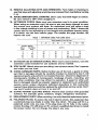
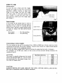
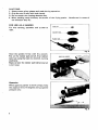
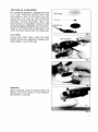
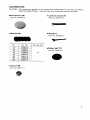
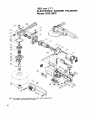
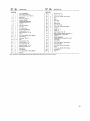
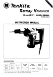
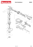
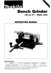
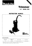
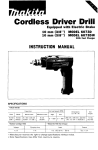
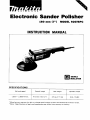
Electronic Sander Polisher
180 mm (7") MODEL 9207SPC
INSTRUCTION MANUAL
DOUBLE
INSULATION
SPEC1FICATIONS
N o load speed
1,500
-
2,800 R/min.
Overall length
Net weight
Spindle thread
4 7 0 m m (18-1/2")
3.5 kg (7.7 Ibs)
5/8-11 UNC
IMPORTANT
SAFETY INSTRUCTIONS
(For All Tools)
WARNING: WHEN USING ELECTRIC TOOLS, BASIC SAFETY
PRECAUTIONS SHOULD ALWAYS BE FOLLOWED TO REDUCE
THE RISK OF FIRE, ELECTRIC SHOCK, AND PERSONAL
INJURY, INCLUDING THE FOLLOWING:
READ ALL INSTRUCTIONS.
-1.
KEEP WORK AREA CLEAN. Cluttered areas and benches invite injuries.
2. CONSIDER WORK AREA ENVIRONMENT. Don't use power tools in damp
or wet locations. Keep work area well lit. Don't expose power tools t o rain.
Don't use tool in presence of flammable liquids or gases.
3. KEEP CHILDREN AWAY. All visitors should be kept away from work area.
Don't let visitors contact tool or extension cord.
4.STORE IDLE TOOLS. When not in use, tools should be stored in dry, and high
or locked-up place - out of reach of children.
5. DON'T FORCE TOOL. It will do the job better and safer at the rate for which
it was intended.
6. USE RIGHT TOOL. Don't force small tool or attachment t o do the job of a
heavy-duty tool. Don't use tool for purpose not intended.
7.DRESS PROPERLY. Don't wear loose clothing or jewelry. They can be caught
in moving parts. Rubber gloves and non-skid footwear are recommended
when working outdoors. Wear protective hair covering t o contain long hair.
a. USE SAFETY GLASSES. Also use face or dust mask if cutting operation is
dusty.
9. DON'T ABUSE CORD. Never carry tool by cord or yank it t o disconnect from
receptacle. Keep cord from heat, oil, and sharp edges.
IO. SECURE WORK. Use clamps or a vise t o hold work. It's safer than using
your hand and it frees both hands t o operate tool.
1 1 . DON'T OVERREACH. Keep proper footing and balance at all times.
12. MAINTAIN TOOLS WITH CARE. Keep tools sharp and clean for better and
safer performance. Follow instructions for lubricating and changing accessories. Inspect tool cords periodically and if damaged, have repaired by authorized service facility. Inspect extension cords periodically and replace if
damaged. Keep handles dry, clean, and free from oil and grease.
13. DISCONNECT TOOLS. When not in use, before servicing, and when changing accessories, such as blades, bits, cutters.
2
0 - 25
26
-
Ampere Rating
More
Not More
Than
Than
0
-
6
-
10
12
-
6
10
12
16
50
51
-
100
101
-
150
AWG
18
18
16
14
16
16
16
12
;:
I
14
12
14
12
Not Recommended
21. REPLACEMENT PARTS. When servicing, use only identical replacement parts.
22. POLARIZED PLUGS. To reduce the risk of electric shock, this equipment has
a polarized plug (one blade is wider than the other). This plug will fit in a
polarized outlet only one way. If the plug does not fit fully in the outlet,
reverse the plug. If it still does not fit, contact a qualified electrician t o install
the proper outlet. Do not change the plug in any way.
3
VOLTAGE WARNING: Before connecting the tool t o a power source (receptacle,
outlet, etc.) be sure the voltage supplied is the same as that specified o n the
nameplate of the tool. A power source w i t h voltage greater than that specified
for the tool can result in SERIOUS INJURY t o the user - as well as damage t o
the tool. If in doubt, DO NOT PLUG IN THE TOOL. Using a power source with
voltage less than the nameplate rating is harmful t o the motor.
SAVE THESE INSTRUCTIONS.
PRECAUTION IN USE
Do not use with D.C. application.
4
HOW TO USE
Switch action
To start the tool, simply pull the trigger.
Release the trigger to stop. For continuous
operation without having to keep your
finger on the tirgger, just pull the trigger
and then push in the lock button with
your thumb. To stop the tool from the
lock position, simply pull the trigger again
and release it.
I
I
Fig. 1
Speed changes
If the knob on the switch lever in front is
turned to the "H" setting, the high speed i s
obtained; if set t o the "L" setting, the low
speed results. Use the suitable speed setting
in order to obtain the best performance
ani finish.
Trigger switch
Speed change knc
iigh speed . . . . . For disc sanding
.ow speed . . . . . . For polishing
Arrow indication
F ig.2
Knob setting in terms of speed
The tool speed can be set for anywhere from 1,500 to 2,800 rpm. Simply align any knob
numbered setting with the arrow indicator. Consult chart below for approximate speeds
obtained for each of the numbered settings.
You can also obtain speeds other than the settings by adjusting the knob in between.
For example, for 2,150 rpm, align so that arrow will be pointed halfway between the
numbers 3 and 4.
CAUTION :
The knob for speed settings can be turned
only as far as 6 and back to 1. Do not force
the knob p a s t 6 or the speed change function may no longer work.
Numbered Setting
5
6
2000
2300
2550
2800
CAUTION
ALWAYS SWITCH OFF AND UNPLUG THE TOOL BEFORE INSTALLING OR REMOVING A SANDING DISC OR WOOL BONNET.
5
CAUTIONS :
1. Always wear safety glasses and mask during operation.
2. Grip the tool firmly with both hands.
3. Do not touch the rotating abrasive disc.
4. When sanding metal surfaces, be careful of the flying sparks. Handle tool in terms of
the direction they fly.
FOR USE AS A SANDER
For disc sanding, assemble tool as seen a t
right.
Abrasive diJc
Fig.
Hold the spindle firmly with the wrench.
Put on the rubber pad and all, then tighten
lock nut using the lock nut wrench, turning
clockwise.
Make certain the rubber pad tightening nut
is not loose.
ock nut wrench
Operation
When applying sander to work surface, keep
the angle a t 10 to 15 degrees and use gentle
pressure only.
Fig. 5
6
FOR USE AS A POLISHER
For polishing operation, assemble the tool
as a t right. Hold the spindle firmly with
the wrench 17. Put on the rubber pad, then
tighten lock nut using the lock nut wrench
provided, turning clockwise. Next, put
wool bonnet on, fastening it securely with
strings as snugly as possible, near the center.
Tuck in the loose ends of the cord in between the wool bonnet and the rubber pad.
.-. .-...
Fig.
C
-,A I ITlnN:
Loose cord ends when using the wool
bonnet can be very dangerous. Always tuck
them safety in out of the way.
E
Lock nut wrench
Fig. 7
Fig. 8
Operation
When polishing, keep the angle a t about 15
degrees and work gently in the direction
the polisher is turning.
Fig. 9
7
MAINTENANCE
CAUTION :
Always be sure that the tool i s switched off and unplugged before attempting to perform
inspection and maintenance.
0
Replacing carbon brushes
Remove and check the carbon brushes
regularly. Replace when they wear down
to the limit mark. Keep the carbon
brushes clean and free to slip in the
holders. Both carbon brushes should be
replaced at the same time. Use only identical carbon brushes.
I /
I
Limit mark
Fig. 1(
8
ACCESSORIES
CAUTION: The accessories specified in this manual are recommended for use with your Makita
Electronic Sander Polisher. The use of any other accessories might be hazardous.
0
Wool bonnet 180
Lock nut wrench 28
(Part No. 743404-0)
(Part No. 782413-4)
Abrasive disc
Wrench 17
(Part No. 781008-0)
Grit
I
16
20
24
30
50
80
100
120
0
Part No.
742067-9
742068- 7
742069- 5
742089-9
742070-0
742071-8
742090-4
742091-2
I
Discs Der
. oka
. -
Rubber pad 170
( P a r t No. 743012-7)
10
Lock nut 48
( P a r t No. 224517
9
180 mm (7")
ELECTRONIC SANDER POLISHER
Model 9207SPC
Note: The switch, noise suppressor and other part configurations
may differ from country to country.
10
'LtM At!
M m
1
E
1
DESCRIPTION
'LtM $tD
DESCRIPTION
MACHINE
Woodruff Key 3
F I E L D ASSEMBLY
(With Garter Spring x 21
28
1
29
1
LockNut 16-48
P H. Screw M 4 x 4 5 (With Washer)
Label
Name Plats
2
2
H. Bolt M 5 x 7 0 IWith Washer)
30
3
1
Baffle Plate
31
2
2
4
1
Ball Bearing WBLB
5
6
1
1
1"S"lauP" Washer
ARMATURE ASSEMBLY
IAIIsmbled Items 4 - 71
32
33
1
1
34
2
Rivet
7
1
Fan 68
35
2
Carbon Brush
8
1
G~~~nourlngCovsr
36
1
2
Tool Rest
2
2
Brush Holder Cap
9
10
1
COntrOlle,
11
1
Ball Bearing 6 0 0 2 L L B
12
1
Retamng Ring S-15
13
14
1
1
Bearing Retainer 1 9 - 3 3
15
4
P H. Screw M5x40 W t h Warherl
16
1
Gear Hourmg
17
1
CapScrew M12x12
18
0-3
19
1
20
1
21
1
22
1
Bearing Retainer 2 2 - 3 4
49
2
P H. Screw M 4 x 6 IWith Washer)
23
1
Ball Bearing 6201 LLB
50
1
SWltCh
2
P. H Screw M 4 x 2 8 IWith Warherl
P H.Screw M5
Label
37
Band
0-5
P. H. Screw M3x6 (With Washer)
38
39
1
Rubber Pin 4
40
1
0 Ring 17
41
42
1
1
Speed Change K n o b 28
Motor Housing IWifh Brush Holder x
' S.
Screw M5x8 x 2 & Item 40)
43
1
Lme coo1
44
1
CORD ASSEMBLY
IAssembled Cord. Plug (I Cord Guard1
Shim
45
1
Cord Guard
Needle Bearing 810
46
1
Strain Relief
Retaining Ring S-12
47
2
P. H Screw M 4 x 1 8 (With Warherl
Spiral Bevel Gear 4 4
48
1
NoireSupprcrrar
24
1
Bearing Box
51
25
26
1
Dust %a1 20
52
1
HandleCovcr
4
P. H. Screw M 4 x 1 4 (With Warherl
400
1
Grip 37
27
1
Spindle
2,
11
MAKEA LIMITED ONE YEAR WARRANTY
Warranty Policy
Every Makita tool is thoroughly inspected and tested before leaving the factory. It is warranted to
be free of defects from workmanship and materials for the period of ONE YEAR from the date of
original purchase. Should any trouble develop during this one-year period, return the COMPLETE
tool, freight prepaid, to one of Makita’s Factory or Authorized Service Centers. If inspection shows
the trouble is caused by defective workmanship or material, Makita will repair (or at our option,
replace) without charge.
This Warranty does not apply where:
8 repairs have been made or attempted by others:
0 repairs are required because of normal wear and tear:
0 The tool has been abused, misused or improperly maintained;
0 alterations have been made to the tool.
IN NO EVENT SHALL MAKITA BE LIABLE FOR ANY INDIRECT, INCIDENTAL OR CONSEQUENTIAL DAMAGES FROM THE SALE OR USE OF THE PRODUCT. THIS DISCLAIMER
APPLIES BOTH DURING AND AFTER THE TERM OF THIS WARRANTY.
MAKITA DISCLAIMS LIABILITY FOR ANY IMPLIED WARRANTIES, INCLUDING IMPLIED
WARRANTIES O F “MERCHANTABILITY” AND “FITNESS FOR A SPECIFIC PURPOSE,”
AFTER THE ONE-YEAR TERM O F THIS WARRANTY.
This Warranty gives you specific legal rights, and you may also have other rights which vary from
state to state. Some states do not allow the exclusion or limitation of incidental or consequential
damages, so the above limitation or exclusion may not apply to you. Some states do not allow
limitation on how long an implied warranty lasts, so the above limitation may not apply to you.
Makita Corporation
3-11-8, Sumiyoshi-cho,
Anjo, Aichi 446 Japan
883403A063
PRINTED IN JAPAN
1992 - 9 - N