1
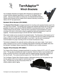
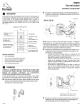
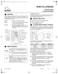
Installation Operation & Maintenance Installation and service must be performed by a qualified installer, service agency, or the gas supplier. C42-VF Vent Free Gas Fireplace This is an unvented gas-fired heater. It uses air (oxygen) from the room in which it is installed. Provisions for adequate combustion and ventilation air must be provided. Refer to page 3. This gas fireplace is for use only with the type of gas indicated on the rating plate. This gas fireplace is not convertible for use with other fuels. Warning: For Your Safety: If the information in this manual is not following exactly, a fire or explosion may result causing property damage, personal injury, or loss of life. Do not store or use gasoline or other flammable vapors and liquids in the vicinity of this or any other appliance. Check local codes and read all instructions prior to installation. Installer: Leave this manual with the appliance. Consumer: Leave this manual for future reference. What To Do If You Smell Gas: • • • • Do not try to light any appliance. Do not touch any electrical switch; do not use any phone in your building. Immediately call your gas supplier from a neighbor's phone. Follow the gas supplier's instructions. If you cannot reach your gas supplier, call the fire department. ® C US C42-VF Gas Fireplace Table Of Contents Installation Introduction .............................................................................. 2 Installation Installing the Fireplace Shell........................................... 2 Installing the Gasline....................................................... 4 The Remote Switch......................................................... 4 Vent Free Installation...................................................... 4 Construction around the fireplace Facing................................................................. 4 Mantels and Surrounds...................................4-5 Wiring . .......................................................................... 5 Removing and Installing the Door................................... 6 Installing the Logset........................................................ 7 Operation ...............................................................................7-8 Maintenance . .......................................................................9-10 Appendix A - Spare Part & Accessories .............................. 11 Warranty .................................................................................. 12 Introduction Thank You for choosing a Montigo C-Series Fireplace. CAUTIONS Due to its high operating temperatures, the appliance should be located out of traffic & away from furniture and draperies. Children and adults should be alerted to the hazards of the high surface temperature, which could cause burns or clothing ignition. Young children should be carefully supervised when they are in the same room as the appliance. Clothing or other flammable materials should not be placed on or near the appliance. Any safety screen or guard removed for servicing an appliance must be replaced prior to operating the heater. Installation and repair should be done by a qualified service person. The appliance should be inspected before use and at least annually by a professional service person. More frequent cleaning may be required due to excessive lint from carpeting, bedding material, etc. It is imperative that control compartments, burners and air-circulating Choosing a Location The C42-VF includes a 32,000 BTU dual burner and 1 piece ceramic fibre logset. The C42-VF is rated for Natural Gas at 32,000 BTU/H Input or Propane at 32,000 BTU/H Input. The fireplace may be installed in a location that maintains proper clearances to air conditioning ducts, electrical wiring and plumbing. Safety, as well as efficiency of operation, must be considered when selecting the fireplace location. Try to select a location that does not interfere with room traffic and has adequate ventilation. Warranty and Installation Information: This fireplace cannot be installed in a bedroom or a bathroom. About the C42 Fireplace: The Montigo warranty will be voided by, and Montigo disclaims any responsibility for, the following actions: Modification of the fireplace and/or components including the firebox door. Use of any component part not manufactured or approved by Montigo in combination with this Montigo fireplace system. Installation other than as instructed in this manual. Consult your local Gas Inspection Branch on installation requirements for factory-built gas fireplaces. Installation & repairs should be done by a qualified contractor. The fireplace dimensions are shown below: Top Veiw Installations in the USA must conform to local codes, or in the absence of local codes to the National Fuel Gas Code, ANSI Z223.11988/ NFPA54. If the optional air-circulating fan is installed, it must be grounded in accordance with local codes or, in the absence of local codes, with the National Electrical Code, ANSI/NFPA 70-1987. WARNING: Any modification to this heater or its controls can be dangerous. Page 2 Front View Figure 1. Fireplace dimensions. Side View Part No. XG0340 C42-VF Gas Fireplace Installation Clearances Framing These clearances apply to all dimensions except the framed opening, where the clearance to combustibles is 0". The C42-VF clearances to combustible materials are: * When sheetrock is not used behind the fireplace, framing depth may be reduced to 17 1/4" Top Back 0" Sides 0" Floor 0" Mantle** 8" Front 3' Figure 2. Framing dimensions. " * Clearance from the top of the fireplace to a combustible ceiling within the fireplace enclosure. ** Refer to page 5. Blank Flammable materials Explosion risk General Warning Laser Radiation Figure 3. Corner framing dimensions. When installing a shelf over the top of the fireplace, the following guidelines must be adhered to: The minimum clearance from the top of the fireplace to a shelf is 5". Toxic Corrosive Danger overhead crane Fork lift trucks warning Biohazard Oxidising Hot surface Danger of entrapment H o t g l ass will cause burns. Do not touch glass until unit cooled. Never allow children to High voltage Danger of death Irritant Slippery floor Watch your step Cutting High temperatures Glass hazard Danger of suffocation Gas bottles Watch for falling objects Electricity Danger for cutter Entrapment hazard Battery hazard Rotating parts Low temperature Strong magnetic field Optical radiation Non ionizing radiation Radiation Hazardous to the Environment Danger of harming your hands Figure 4. Framing for shelves over the fireplace. WARNING: When this appliance is installed directly on carpeting, tile or any combustible material other than wood flooring, it must be installed on a metal or wood panel extending the full width and depth of the appliance. Part No. XG0340 Page 3 C42-VF Gas Fireplace Installation Unusually tight construction is defined as construction where: Walls and ceilings exposed to the outside atmosphere have a continuous water vapour retarder with a rating of 1 perm ( 6x 10 -11 kg per pa-sec-m2) or less with openings gasketed or sealed, and Weather Stripping has been added on openable windows and doors, and Caulking or sealants are applied to areas such as joints around window doors and frames, between sole plates and floors, between wall-ceiling joints, between wall panels, at penetrations for plumbing, electrical and gas lines, and at other openings. Installing The Gas Line The gas line must be installed before finishing the C42-VF Fireplace. Natural Gas requires a minimum inlet gas supply pressure of 5.5" W.C. & a manifold pressure of 3.5" W.C. Propane Gas requires a minimum inlet gas supply pressure of 11" W.C. & a manifold pressure of 10" W.C. Provision must also be made for a 1/8" N.P.T. plugged tapping and be accessible for test gauge connection immediately upstream of the gas supply controls to the appliance. The fireplace gas connection and the main operating gas valve is located behind the removable brass trim at the bottom of the unit and need only be attached to the gas line with an approved fitting, as required by the applicable installation codes. WARNING: Do not allow fans to blow directly into the fireplace. Avoid any drafts that alter burner flame patterns. 1 Keep appliance area clear and free from combustion materials, gasoline and other flammable vapors and liquids. 4 1/2 Gasline access 3 ¼ x 2 1/2" Figure 6. Gas line access. The appliance and its individual shutoff valve must be disconnected from the gas supply piping system during any pressure testing of that system at test pressures in excess of 1/2 psig (3.5 kPa). The appliance must be isolated from the gas supply piping system by closing its individual manual shutoff valve during any pressure testing of the gas supply piping system at test pressures equal to or less than 1/2 psig (3.5 kPa). Note: After gas line is connected, each appliance connection, valve and valve train must be checked while under normal operating pressure with either a liquid solution, or leak detection device, to locate any source of leak. Tighten any areas where bubbling appears or leak is detected until bubbling stops completely or leak is no longer detected. DO NOT use a flame of any kind to test for leaks. Installing The Remote Switch The C42-VF's gas valve, located behind the lower trim, may be connected to a wall switch. The valve generates its own power on a millivolt circuit. Use only low voltage wire, and DO NOT connect any external power to it. Refer to Figure 13 for wiring requirements. Note: The switch location must not exceed 30' from the fireplace. Page 4 Part No. XG0340 C42-VF Gas Fireplace Installation Finishing Around the Fireplace Combustible mantels and mouldings may be safely installed over the top and on the front of the fireplace provided that they do not project beyond shaded area shown in Figure 7a. Side wall clearances are 3". Combustible surrounds may be installed with 3" clearance to the side of the fireplace as shown in Figure 7b. Fireplace Facing When selecting the finish material for your fireplace, it is important to remember the following: TRIMS MUST NOT BE OBSTRUCTED IN ANY WAY - to do so restricts the air supply for the control compartments and heat exchanger it also prevents access for servicing controls. Association, when painting the fireplace surrounds, to select and apply a quality Alkyd sealer prior to the applying of latex paints. This is to prevent leaching of water from evaporation and causing a brownish staining effect to paint over coats. Sheetrock/ Drywall Header The face of the fireplace may be painted to match the room decor, provided you use a heat-resistant paint. Decorative facing must not extend past the fireplace opening at all, because it will interfere with the access to retainers for removal of screen door. 45° 3 Figure 7b. Combustible surrounds. Figure 7a. Combustible mantles and facings. Mantels & Surrounds New technology, to meet consumer and government demands for the wise use of energy, has prompted us to manufacture many models of fireplaces which are hot, fuel and energy efficient. Please be aware; temperatures over the mantel will rise above normal room temperature and walls above fireplace may be hot to touch. We recommend careful consideration be given to the effects of elevated mantel temperatures which may be in excess of product design, for example: candles, plastic or pictures. This can cause melting, deformation, discoloration or premature failure of T.V. and radio components. Painting: Part No. XG0340 Page 5 C42-VF Gas Fireplace Installation Removing and Installing the Door Removing the Door: Remove the trim (as described on the next page) to access the door latches. Open the latches by pulling Part A upwards and towards you to disengage Part B from the door. Lift Part B clear of the door. Repeat for all three latches. Be sure to hold the door carefully so it does not fall. (See figure 8a.) Figure 8c. Removing the door. Re-installing the door: To re-install the door, tilt the top edge towards you and line up the tabs of the bottom of the door with the slots on the fireplace. Place the tabs into the slots, and tilt the top of the door back towards the fireplace as far as it will go. Close the latches by hooking Part B onto the groove at the top of the door and pushing Part A down completely. Installing the Logset Installing the Logs: The C42-VF is supplied with a single-piece,moulded design, fibre logset. The logset is very fragile and must be handled very carefully. Figure 8a. Operating the door latches. 1. Remove the door as shown in Figures 8a-8c. 2. To install the logs, align the pins on the bottom of the log rest with the holes in the bottom of the logset. 3. Re-install the screen door before operating the fireplace. Removing the Logs: Remove the door and carefully lift the logset off the two guide pins. Handle the logs very carefully. Log 'B' Log 'C' Figure 8b. Removing the door. Once the three latches are unhinged, tilt the top of the door forward and lift it out of the slots. See figures 8b and 8c. Caution: ■ The screen door must be replaced prior to oper- ating the heater. Log 'A' Figure 9a. Positioning for the logset. Cautions: ■ If logs are not placed properly, excessive sooting will result. ■ The surface of the logs will crack due to the heat from the flames. This is a normal occurance. ■ The use of ember material is strictly prohibited. Page 6 Part No. XG0340 C42-VF Gas Fireplace Operating Instructions For Your Safety - READ BEFORE LIGHTING: WARNING: If you do not follow these instructions exactly, a fire or explosion may result causing property damage, personal injury or loss of life. A. This appliance has a pilot which must be lit by hand. When lighting the pilot, follow these instructions exactly. B. BEFORE LIGHTING smell all around the appliance area for gas. Be sure to smell next to the floor because some gas is heavier than air and will settle on the floor. What To Do If You Smell Gas: Do not try to light any appliance. Do not touch any electrical switch; do not use any phone in your building. Immediately call your gas supplier from a neighbour's phone. Follow the gas supplier's instructions. If you cannot reach your gas supplier, call the Fire De- partment. C. Use only your hand to push in or turn the gas control knob. Never use tools. If the knob will not push in or turn by hand, don't try to repair it, call a qualified service technician. Force or attempt to repair may result in a fire or explosion. D. Do not use this appliance if any part has been under water. Immediately call a qualified service technician to inspect the appliance and to replace any part of the control system, and any gas control which has been under water. Lighting Instructions: 1. 2. 3. 4. STOP! Read the safety information above on this label. Flip down the lower trims. to "OFF." Push in gas control knob and turn clockwise Wait five (5) minutes to clear out any gas. Smell for gas, including near the floor. If you then smell gas, STOP! Follow "B" in the safety information above on this label. If you don't smell gas, go to the next step. 5. Locate pilot burner (See illustration at right.) and follow steps below. to "PI6. Turn knob on gas control counterclockwise LOT." 7. Push in gas control knob completely and hold. Light with Gas Control Knob (Shown in "Pilot" postion.) Piezo Igniter button. Continue to hold the control knob in for about (1) minute after the pilot is lit. Release the knob and it will pop back up. Pilot should remain lit. If it goes out repeat steps 3 through 8. If knob does not pop up when released. Stop and immediately call your service technician or gas supplier. If the pilot will not stay lit after several tries, turn the gas control knob to "OFF" and call your service technician or gas supplier. 8. Push in gas control knob and turn counterclockwise to "ON." 9. Flip up the lower trim. 10.Turn on remote switch to ignite fire. NOTE: Knob cannot be turned from "PILOT" to "OFF" unless knob is pushed in slightly. Do not force. To Turn Off Gas To Appliance: 1. Turn off remote switch. 2. Flip down the lower trim. Part No. XG0340 3. Push in gas control knob slightly and turn to "Off". Do not force. 4. Flip up the lower trim. clockwise Page 7 C42-VF Gas Fireplace Operating Instructions Lighting Instructions See page 7. Burner Adjustment The C42-VF is equipped with an adjustable burner, allowing you to raise or lower the flames. To adjust the flames, locate the black knob marked 'Hi-Lo', in the centre of the gas control valve (See Figure 10). The front burners are not adjustable. ■ To raise the flame height, turn the black knob (located behind the lower trim) counterclockwise. ■ To lower the flame height, turn clockwise. Maintenance CAUTIONS Fireplace gas control must be in the “OFF” position and pilot and main burners extinguished when cleaning appliance with a vacuum. Doors and logs can get very hot. Handle only when General Have the fireplace installation inspected yearly, including a visual check of the burner and the pilot flame. For your convenience a 1/8" manifold pressure tap is supplied on the gas valve for a test gauge connection. See Figure 11. For Natural Gas this appliance requires a minimum inlet pressure of 5.5" W.C. and a manifold pressure of 3.5" W.C. For Propane Gas this appliance requires a minimum inlet pressure of 11" W.C. and a manifold pressure of 10" W.C. Always keep the fireplace area clear and free of combustible materials, as well as gasoline and other flammable vapours and liquids. Do not use this appliance if any part has been under water. Immediately call a qualified service technician to inspect the appliance and to replace any part of the control system and any gas control which has been under water. Cleaning Figure 10. 'Hi-Lo' Adjustment on the C42-VF's gas valve. When the fireplace is first activated, there may be some smoking. This is a normal condition, and is the result of burning of protective coatings on new metal. Silicone seals on inner door during initial firing will "off gas", leaving a visual deposit of a white substance on combustion chamber walls. This can easily be removed using normal household products. Use a vacuum cleaner or whisk broom to keep the control compartment, burner, and firebox free from dust and lint. Logs may be cleaned periodically with a vacuum to remove soot WARNING: Do not attempt to clean the fireplace when hot. Page 8 Part No. XG0340 C42-VF Gas Fireplace Maintenance Wiring for the optional Fan Kit Gas Control Valve Power Generator All C42-VF fireplaces may be equipped with an optional fan kit (Part no. RFK1002 or RFK1003)for circulating heat into the living space. Kits are available with manual or heat-activated control. Wall Switch Installations which employ the fans must be grounded in accordance with local codes or, in the absence of local codes, with the National Electrical Code, ANSI/NFPA 70-1987. Pilot Adjustment Screw For more information see the Fan Kit Installation Guide included with the fan kit. Inlet Pressure Manifold Pressure Test Connection Figure 11. SIT NOVA 820.637 for NG, SIT NOVA 820.636 for LP. Pilot Burner Adjustment NOTE: If any of the original wire as supplied with the appliance must be replaced, it must be replaced with a wire of at least a 60 º temperature rating. L2-WH G L1-BLK 1. Locate Pilot Adjustment Screw. (See figure 11.) 2. Adjust pilot screw to provide properly sized flame as shown in figure 12). 3. After installing or servicing, leak test with a soap solution with main burner on. Coat pipe and tubing joints, gasket etc. with soap solution. Bubbles indicate leaks. Tighten any areas where the bubbles appear until the bubbling stops completely. Quick Connect plug to motor Figure 13a. Wiring for optional air circulating fan kit. 115/1/60 Supply G L1 L2 Figure 12. Pilot Burner Troubleshooting The following is a troubleshooting chart of possible problems: PROBLEM CORRECTIVE ACTION Noisy Pilot Flame Locate pilot adjustement screw on gas control valve. Flame is decreased by turning adjustment screw clockwise. Pilot won’t ignite Disconnect remote wires and try to light pilot. If pilot now works, remote connections are faulty. Check wiring diagram figure 11. Main burner will not light 1. Check wiring (see figure 11). 2. Check wall switch for proper connection. Part No. XG0340 Figure 13b. Wiring schematic for optional fan kit. WARNING: Do not allow fans to blow directly into the fireplace. Avoid any drafts that alter burner flame patterns. Do not use a blower insert, heat exchanger insert or other accessories not approved for use with this heater. Page 9 Page 10 When contacting dealer or Montigo, please have the following ready. - Your name and address - Part number and description of part or accessories to be replaced - Model and serial numbers of your heaters - Type of Gas used (Natural Gas or LP/Propane gas) - Purchase date Canadian Heating Products & Montigo Delray Corp 27342 Gloucester Way Langley, BC, V4W 4A1 Contact authorized dealers of this product. If they can not supply original replacement part(s), Call toll free at 1-800-378-3115. Note: Use only original replacement parts. This will protect your warranty coverage for parts replaced under warranty. C42-VF Gas Fireplace Appendix A - Spare Parts & Accessories Part No. XG0340 C42-VF Gas Fireplace Warranty The Warranty Montigo DelRay Corp. warrants the Montigo Gas Appliance to be free from defects in materials and workmanship at the time of manufacture. On the Montigo, there is a ten-year warranty on the firebox and its components, a five-year warranty on the main burner and pilot burner, and a one-year warranty on the gas control valve and fibre logs. Screen, plated/painted finishes, and refractory lining are exempt. Remedy And Exclusions The coverage of this Warranty is limited to all components of the Gas Appliance manufactured by Montigo DelRay Corp.. This Warranty only covers Montigo Gas Appliances installed in the United States. If the components of the Gas Appliance covered by this Warranty are found to be defective within the time frame stated (see Montigo DelRay Corp. right of investigation outlined below). Montigo DelRay Corp. will, at its option, replace or repair defective components of the Gas Appliance manufactured by Montigo DelRay Corp. at no charge, and will also pay for reasonable labour costs incurred in replacing or repairing components. If repair or replacement is not commercially practical, Montigo DelRay Corp. will, at its option, refund the purchase price of the Montigo Gas Appliance. This Warranty covers only parts and labour as provided above. In no case shall Montigo DelRay Corp. be responsible for materials, components, or construction which are not manufactured or supplied by Montigo DelRay Corp., or for the labour necessary to install, repair or remove such materials, components or construction. All replacement or repair components will be shipped F.O.B. the nearest Montigo DelRay Corp. factory. Qualifications To The Warranty The Gas Appliance Warranty outlined above is further subject to the following qualifications: (1) The Gas Appliance must be installed in accordance with Montigo DelRay Corp. installation instructions and local building codes. The Warranty on this Montigo Gas Appliance covers only the component parts manufactured by Montigo DelRay Corp.. The use of components manufactured by others with this Montigo Gas Appliance could create serious safety hazards, may result in the denial of certification by recognized national safety agencies, and could be in violation of local building codes. This warranty does not cover any damages occurring from the use of any components not manufactured or supplied by Montigo DelRay Corp. (2) The Montigo Gas Appliance must be subjected to normal use. The Gas Appliances are designed to burn gas only. Burning conventional fireplace fuels such as wood, coal or any other solid fuel will cause damage to the Gas Appliance, will produce excessive temperatures and will result in a fire hazard. Limitations On Liability It is expressly agreed and understood that Montigo DelRay Corp. sole obligation, and purchaser's exclusive remedy under this Warranty, under any other warranty, expressed or implied, or in contract, tort or otherwise, shall be limited to replacement, repair, or refund, as specified above. In no event shall Montigo DelRay Corp. be responsible for any incidental or consequential damages caused by defects in its products, whether such damage occurs or is discovered before or after replacement or repair, and whether or not such damage is caused by Montigo DelRay Corp. negligence. Some states do not allow the exclusion or limitation of incidental or consequential damages, so the above limitation or exclusion may not apply to you. The duration of any implied warranty with respect to this Montigo Gas Appliance is limited to the duration of the foregoing warranty. Some states do not allow limitation on how long an implied warranty lasts, so the above may not apply to you. Investigation Of Claims Against Warranty Montigo DelRay Corp. reserves the right to investigate any and all claims against this Warranty and to decide upon method of settlement. Montigo DelRay Corp. Are Not Responsible For Work Done Without Written Consent Montigo DelRay Corp. shall in no event be responsible for any warranty work done without first obtaining Montigo DelRay Corp. written consent. Dealers Have No Authority To Alter This Warranty Montigo DelRay Corp. employees and dealers have no authority to make any warranties nor to authorize any remedies in addition to or inconsistent with those stated above. How To Register A Claim Against Warranty In order for any claim under this Warranty to be valid, Montigo DelRay Corp. must be notified of the claimed defect in writing or by telephone, as soon as reasonably possible after the defect is discovered. Claims against this Warranty in writing should include the date of installation, and a description of the defect. Montigo DelRay Corp. reserves the right to make changes at any time, without notice, in design, materials, specifications, prices and also to discontinue colors, styles and products. Part No. XG0340 Page 11 Installed and Serviced by: XG0340 Rev. 0 - 10/2004 Montigo Del Ray Corp. 6955 Salashan Parkway Ferndale, WA 98248 27342 Gloucester Way, Langley, BC