1
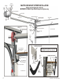
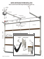
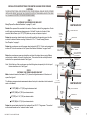
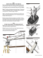
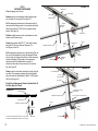
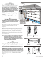
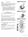
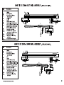
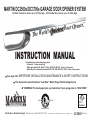
MARTIN DC2500e/DC3700e GARAGE DOOR OPENER SYSTEM
DC2500e Chain Drive: Doors up to 10’(3100) High. DC3700e Belt Drive: Doors up to 14’ (4300) High.
™
.
r
e
n
e
p
O
r
o
o
D
t
s
e
t
e
i
u
Q
s
’
d
l
r
o
W
e
h
T
INSTRUCTION MANUAL
For Installation on residential garage doors:
-All brands* - Center mount only
-Martin door models WL, RA, HT, FL SL, SP CM, RI, MO, CH - Center or side mount
-Martin Electric (combination) models WLE, HTE, CME, RAE, FLE, CHE - Center or side mount
See page 5 for
IMPORTANT INSTALLATION, MAINTENANCE & SAFETY INSTRUCTIONS
This instruction manual features “Low Risk” Martin Finger Shield Garage Doors
*WARNING! The back page helps you determine if your garage door is “HIGH RISK”.
TM
RM
ST
ISO 9001
FI
N
R E GI
M
ARTI
DOOR OPENERS
C
A8949
ERED
UL
R
US
F.C.C.
Certified
MARTIN DOOR MFG.
Martin Door Manufacturing® Salt Lake City, Utah 84127-0437 USA
www.martindoor.com Printed in the USA 20m Copyright © 2003
11/2003 AD-IM09-06
OPTIONAL
PUNCHED ANGLE
“C”
BRACKETS
MARTIN SIDE-MOUNT OPENER INSTALLATION
- May be mounted right side or left side WARNING! For Martin Finger Shield Garage Door Systems only.
POWER
HEAD
CHASSIS
RAIL SUPPORT BRACKET
RAIL ASSEMBLY
OPENER HEADER BRACKET
BELT OR CHAIN
POWER
HEAD
END STOP WITH CLEVIS
PIN AND COTTER RING
LIGHT
LENS
TORSION TUBE
TROLLEY
“L” STRUT
TORSION SPRING
OPENER HEADER
BRACKET
END STOP WITH CLEVIS
PIN AND COTTER RING
EMERGENCY
RELEASE
CORD
OPENER DOOR BRACKET
TOP DOOR SECTION
EMERGENCY
RELEASE
TAG
STRAIGHT AND CURVED
POWER ARM
KNOB
WALL
CONTROL
OR
PUSH
BUTTON
OPENER DOOR BRACKET
3/8” X 1” SHORT NECK
CARRIAGE BOLT AND
3/8” LOCK NUT
OPENER POWER ARM MUST BE FASTENED
OUTSIDE THE OPENER DOOR BRACKET
“L” STRUT
3/8”x1”
SHORT
NECK
CARRIAGE
BOLT
OPENER DOOR BRACKET
OPENER DOOR BRACKET
“L” STRUT (IF PROVIDED)
3/8” X 1” SHORT NECK
CARRIAGE BOLT AND
2- 3/8” LOCK NUTS
3/8” LOCK NUTS
TOP ROLLER BRACKET
TOP ROLLER
BRACKET
PHOTO
EYE
TOP DOOR SECTION
CURVED
POWER ARM
END
STILE
2
COPYRIGHT © 2003 MARTIN DOOR
MARTIN CENTER-MOUNT OPENER INSTALLATION
- May be mounted off-center for Martin Finger Shield Garage Door Systems only OPTIONAL
“C”
PUNCHED ANGLE
BRACKETS
POWER
HEAD
CHASSIS
RAIL SUPPORT BRACKET
RAIL ASSEMBLY
OPENER HEADER BRACKET
POWER
HEAD
END STOP WITH CLEVIS
PIN AND COTTER RING
BELT OR CHAIN
LIGHT
LENS
TROLLEY
“L” STRUT
TORSION TUBE
EMERGENCY
RELEASE
CORD
TORSION SPRING
OPENER DOOR BRACKET
EMERGENCY
RELEASE
TAG
KNOB
TOP DOOR SECTION
STRAIGHT AND CURVED
POWER ARM
WARNING AND SAFETY LABEL
WALL
CONTROL
OR
PUSH
BUTTON
PACKET FOR OWNERS
DOOR AND OPENER
INSTRUCTION MANUALS
OPENER POWER ARM SHOULD BE FASTENED INSIDE THE OPENER DOOR BRACKET
3/8”x1” SHORT NECK
CARRIAGE BOLT
OPENER DOOR BRACKET
CURVED
POWER ARM
“L” STRUT
CURVED
POWER
ARM
PHOTO
EYE
3/8” LOCK NUTS
DRILL 1/8” (3) HOLE AND FASTEN OPENER
COPYRIGHT © 2003 MARTIN DOOR
PHOTO
EYE
DOOR BRACKET TO “L” STRUT AND DOOR SECTION
3
!
TO REDUCE THE RISK OF SEVERE INJURY OR
DEATH, READ AND FOLLOW ALL INSTRUCTIONS
Do not install this opener or any other opener on "HIGH RISK" garage doors that may cause severe injury, entrapment or death!
See back page for serious injuries which may occur if “HIGH RISK” areas are left uncorrected.
Martin Finger Shield Garage Doors are “Low Risk”.
IMPORTANT
INSTALLATION INSTRUCTIONS
IMPORTANT
MAINTENANCE & SAFETY INSTRUCTIONS
Untrained or Negligent Installing, Adjusting and Servicing can be Dangerous! The
garage door springs and related parts can cause serious injury or death! IF YOU ARE
UNSURE, CALL A TRAINED MARTIN DOOR DEALER!
Monthly, check the opener's down cycle safety reverse. The door must reverse when it
contacts a 1 1/2" (38) high object (or a 2X4 board laid flat) on the floor, in line with the door
opener. A closing door must also reverse if the photo eyes are interrupted. See Steps 12,13.
Garage door should be balanced and easy to open and close by hand.
Always keep the moving door in sight and away from people and objects until it is
completely closed. NO ONE SHOULD CROSS THE PATH OF THE MOVING DOOR.
Locks should be disabled and pull down ropes should be removed.
NEVER GO UNDER A STOPPED, PARTIALLY OPEN DOOR
Locate wall control/push button within sight of door, at min. height of 5' (1520) so
small children cannot reach it, and away from all moving parts of door. See Step 8.
Emergency release tag should be installed above knob and adjusted to about
6' (1830) above the floor.
Risk of electrical shock is explained in Step10. Do not connect opener to source
of power until instructed to do so.
Do not allow children to operate or play with the garage door opener controls. Keep all
remote controls away from children.
The emergency release should only be used when garage door is in the closed position.
Weak or broken springs may cause door to fall if released in the open position, increasing
the risk of severe injury or death. Use caution when using the release with door open.
Monthly visually check the lift cables, spring assembly, hardware, etc. for wear and stability.
Entrapment and warning labels should be installed next to the wall control/push
button as explained in Step 14.
If the Safety Reverse or any other part of the garage door and opener system do not work
properly, or if you do not understand, call a trained Martin Door Dealer.
SAVE THESE IMPORTANT INSTRUCTIONS
THE FOLLOWING ITEMS ARE HELPFUL TO COMPLETE A SATISFACTORY MARTIN GARAGE DOOR AND OPENER INSTALLATION:
12.
13.
14.
15.
Hammer
ALL MEASUREMENTS IN
Level (magnetic)
PARENTHESIS ( ) ARE
Hacksaw
MILLIMETERS IN THIS
Wire Cutters
INSTRUCTION MANUAL.
18’ (5.5) measuring tape
Socket wrench set for 7/16“ (11), and 9/16” (14) with 3“ (76) extension
Regular and phillips screwdriver
End wrench set for 7/16“ (11), and 9/16” (14)
10/40 motor oil lubricant
Wax lubricant (paraffin, candle, etc.)
Cordless drill with 1/8“ (3), 13/64” (5), 1/4” (6) bits
plus 1/4” and 3/8” (6 and 10) masonry bits
Step ladder (not shown)
Pencil
Punched angle opener hanger: 8' X 1-1/4" X 1-1/4" (2440 X 32 X 32)
Needle nose piler and wire stripper.
NOTE: Bolts, lock nuts and lag screws for fastening the punched angle are
furnished with the door opener hardware fasteners.
COPYRIGHT © 2003 MARTIN DOOR
2.
1.
WAX LUBE
1.
2.
3.
4.
5.
6.
7.
8.
9.
10.
11.
13.
3.
10.
4.
9.
10/40
MOTOR
OIL
MARTI
GAR
AGE
5.
DO O
RS
6.
6.
N
TM
8.
7.
15.
14.
11.
5
OPENER DOOR BRACKET GUIDELINES
FIGURE A
ONLY Martin Finger Shield Garage Door Systems allow you
to choose center, off center or side mounting for a safer,
more attractive opener installation. See page 2 and 3
SIDE MOUNT 12”(305) CLEARANCE
ONE STRAIGHT POWER ARM AND
ONE REVERSED CURVED POWER ARM.
BOTH FASTENED TOGETHER AT A 45° ANGLE.
WARNING! Other brand doors are designed for center mounted
openers only. Off center or side mounted installations may result
in other brand doors binding, side shifting, twisting, and falling, as
the lift cables may detach from the cable drums.
A Martin Opener requires 1 1/2" (38) more clearance than the
required garage door clearance.
Opener Door Bracket Exception
Martin Doors over 18'2" (5540) wide, high wind Martin Doors
and Martin wood doors over 10’2”(3100) wide use 3 1/4”(83)
wide “U” struts that fasten over top roller brackets . The opener
door bracket fastens on top of this “U” strut, at any location
with four 1/4”(6) thread forming screws. With the door in the
closed position, fasten straight power arm to reversed curved
power arm (curve may be cut off). The reversed curved power
arm is first fastened to opener door bracket. Fasten power
arms together at about a 45° angle for smooth opening and
closing of door. For low clearance installations, try using the
straight power arm only for fastening to the opener door
bracket.
See Figures A,B
MARTIN OPENER DOOR BRACKET FASTENED TO
3 1/4”(83) WIDE “U” STRUT
FIGURE B
CENTER MOUNT 8”(204)
LOW CLEARANCE
OPTIONAL POWER ARM ANGLE
OIL
BOLT
FASTEN OPENER POWER
ARM DIRECTLY TO HOLE
AT SAME HEIGHT AS
TOP ROLLERS
BOLT
HEAD
OPENER
POWER
ARM
ONE STRAIGHT POWER ARM FASTENED
AT A 45° OR MORE ANGLE
FASTEN TWO
NUTS TIGHT
AGAINST
POWER ARM
ANGLE
STILE
FULL HEIGHT
POWER ARM
ANGLE
POWER ARM
ANGLE
MARTIN OPENER DOOR BRACKET
FASTENED TO CENTER STILE AND
REVERSED “L” STRUT.
(FASTEN POWER ARM ANGLE TO STILE WITH 5 1/4” X 1” THREAD FORMING SCREWS AS SHOWN.)
6
COPYRIGHT © 2003 MARTIN DOOR
INSTALLATION INSTRUCTIONS FOR MARTIN GARAGE DOOR OPENER
SYSTEMS
FIGURE 1
THIN VERTICAL MARK
HEADER
THESE INSTRUCTIONS ARE INTENDED FOR PROFESSIONAL GARAGE DOOR OPENER
INSTALLERS. READ THROUGH THE COMPLETE INSTRUCTION MANUAL AND APPLICABLE
SUPPLEMENTAL INSTRUCTIONS BEFORE BEGINNING.
STEP 1
FASTENING THE OPENER DOOR BRACKET
Study "Opener Door Bracket Guidelines” on page 2, 3, and 6.
Decide if the opener will be mounted to the center, off center or side of the garage door. Center
and off center mounted openers always require a “full width” top strut on the door. If side
mounted, Martin Doors up to 12'2" (3700) wide may or may not require a top strut.
Fasten the opener door bracket under the top roller bracket for side mounting or on the stile
and strut for center/off center mounting. Fasten with 1/4” x 1” Thread Forming Screws.
See “Exception” on page 6.
Fasten the curved power arm to the opener door bracket with 3/8" X 1" short neck carriage bolt
and two 3/8" lock nuts as shown in the “Opener Door Bracket Guidelines” on page 2 and 3.
Raise the curved opener power arm straight up and touch the torsion tube or spring. Make a
vertical mark on header, in line with the power arm. This mark will be the vertically centered
location for the opener header bracket. See Figure 1
Note: To hold the top of the curved power arm from falling down, temporarily tie it to the top of
the door bracket or strut. See Figure 1
CENTER MOUNT
CURVED POWER ARM
REQUIRED
“FULL WIDTH”
“L” STRUT
TEMPORARY TIE
3/8” X 1” SHORT NECK
CARRIAGE BOLT AND
2- 3/8” LOCK NUTS
FIGURE 2
THIN VERTICAL MARK
THIN
HORIZONTAL
MARK
11 ½” (292)
Regular Clearance
11 1/2" (292) for 12” (305) regular clearance track.
6 1/2" (165) for 8" (203) low clearance track.
OPENER HEADER
BRACKET
HEADER
STEP 2
FASTENING THE OPENER HEADER BRACKET
Make a horizontal mark on the header 2" (51) above the highest movement of the door as it
opens. See figure 2.
The following are approximate measurements above the top of a closed door to the horizontal
mark on the header:
OPENER DOOR
BRACKET
1/4” X 1” THREAD
FORMING SCREWS
5/16” X 2” LAG SCREWS
CENTER MOUNT
CURVED POWER ARM
REQUIRED
“FULL WIDTH”
“L” STRUT
TEMPORARY TIE
5" (127) for 4 1/4" (108) low clearance track.
3 1/2" (89) for 2 ½" (64) low clearance track.
Fasten the opener header bracket to the header with two 5/16" X 2" lag screws. The vertical
and horizontal marks are the “centered location” marks.
COPYRIGHT © 2003 MARTIN DOOR
TOP OF
CLOSED DOOR
1/4” X 1” THREAD
FORMING SCREWS
OPENER DOOR
BRACKET
7
STEP 3
FASTENING THE RAIL ASSEMBLY TO THE POWER HEAD
Place the rail assembly onto the power head chassis by lining up the sprocket assembly
opening with motor shaft. Make sure the shaft engages teeth inside sprocket assembly.
Press rail assembly down firmly onto shaft and power head chassis. DO NOT HAMMER!
FIGURE 3
6 X 14 mm
CHASSIS SCREW
Fasten 2 "C" brackets over rail assembly and onto chassis. Flanges on "C" brackets must
fit into the four recessed areas on chassis. The rail assembly must be at a right angle to
the power head for the "C" brackets to fit properly. See Figure 3
“C” BRACKET
SPROCKET
OPENING
RAIL ASSEMBLY
Insert 6 X 14 mm chassis screws through "C" bracket holes and into chassis holes, and
tighten screws by hand with a phillips screw driver. The “C” brackets must firmly hold rail
assembly to chassis. See Figures 3, 4.
POWER HEAD CHASSIS
Do not remove tape around the trolley and straight power arm until Step 9. The trolley
has been taped at the correct location so that the belt or chain position tab will activate the
position switch, and opener computer correctly. The activation begins when the opener
opens the door, from the closed position, for the first time. See Figure 5
POSITION SWITCH
STEP 4
FASTENING THE RAIL ASSEMBLY TO THE OPENER HEADER BRACKET
Place power head on stepladder, positioning front of rail assembly on torsion tube (or on
torsion spring if side mounted) for stability. See Figure 5
FIGURE 4
“C” BRACKETS
POWER HEAD CHASSIS
Position rail assembly end-stop within the opener header bracket and insert clevis pin
through the end-stop and opener header bracket. Attach the
cotter ring to the end of the clevis pin. See Figure 6
MOTOR
SHAFT
6 X 14 MM CHASSIS
SCREW
OPENER HEADER BRACKET
“TAPE AROUND TROLLEY”
(DO NOT REMOVE UNTIL
STEP 9)
FIGURE 5
SPROCKET
ASSEMBLY
OPENING
TORSION SPRING
TIE
TORSION TUBE
POWER HEAD
CURVED POWER ARM
RAIL ASSEMBLY
FIGURE 6 (Top View)
TOP DOOR SECTION
OPENER HEADER BRACKET
“C” BRACKET
END STOP
CLEVIS PIN
POWER HEAD
TOP DOOR
SECTION
LADDER
8
Y
BL
EM
S
AS
IL
RA
COTTER RING
COPYRIGHT © 2003 MARTIN DOOR
STEP 5
MOUNT OPENER TO CEILING
Raise the opener power head high enough to allow the door to be
fully opened. OPEN DOOR BY HAND. Set a 1 ½" (38) high
object on the top part of the door, under the rail assembly. Center
the rail assembly with the opener door bracket. See Figure 11
FIGURE 9
FIGURE 7
3/8” X 1” SHORT NECK
CARRIAGE BOLTS
RAIL
ASSEMBLY
TWIST
IL
RA
E
Y
BL BL
SI M
VI E
IN ASS
5” (127)
PUNCHED
ANGLE
Twist rail support bracket onto rail assembly. See Figures 7
and 8
RAIL
SUPPORT
BRACKET
Slide the rail support bracket forward or backward on the rail
assembly to the best location for fastening to the ceiling. See
Figure 8
FIGURE 8
RAIL ASSEMBLY
I
RA
E LY
L
B B
SI M
VI E
I N AS S
Fasten the 5” (127) punched angle and the rail support
bracket locks to the rail support bracket. See Figure 9
Fasten optional punched angle diagonally from 5” (127)
punched angle to ceiling for correct stability. See Figure 11
POWER HEAD
RAIL
SUPPORT
BRACKET
NOTE: If clearance is limited, the rail support bracket can be
fastened directly to the ceiling with no 5” (127)
punched angle or rail support bracket locks.
See Figure 8
FIGURE 10
RAIL SUPPORT
BRACKET
L
RAIL SUPPORT
BRACKET LOCK
3/8” LOCK NUTS
RAIL ASSEMBLY
5” (127)
PUNCHED
ANGLE
Fasten one extra rail support bracket to center part of rail furnished for doors 10’(3100) to
12’(3700) high. Fasten two extra rail support brackets spaced equally apart on rails furnished
for doors 14’(4300) high. See Figure 11A
RAIL SUPPORT
BRACKET
FIGURE 11
5/16” X 2” LAG SCREW
RAIL SUPPORT
BRACKET LOCK
“C” BRACKET
POWER HEAD
CHASSIS
OPTIONAL PUNCHED ANGLE
1 1/2” (38) HIGH
OBJECT
FIGURE 11A
RAIL SUPPORT BRACKET
RAIL ASSEMBLY
OPTIONAL
PUNCHED ANGLE
RAIL SUPPORT BRACKET
POWER HEAD
TOP DOOR SECT
ION
“L” STRUT
RAIL ASSEMBLY
POWER HEAD
CURVED POWER ARM
COPYRIGHT © 2003 MARTIN DOOR
TEMPORARY TIE
ONE EXTRA RAIL SUPPORT BRACKET
ON RAIL FURNISHED FOR DOORS
10’(3100) TO 12’(3700) HIGH.
TWO EXTRA RAIL SUPPORT BRACKETS
ON RAILS FURNISHED FOR DOORS
14’(4300) HIGH.
9
STEP 6
LIGHT BULBS AND LIGHT LENSES
Twist 2 light bulbs (1 for DC2500e), maximum 60W, into light bulb sockets.
Position light lens tabs with corresponding slots in power head and chassis and snap
into place. Two screws are also furnished to fasten bottom part of DC3700e light lenses.
See Figure 12A or 12B
STEP 7
PHOTO EYES SAFETY SYSTEM
IMPORTANT! CLOSE DOOR BY HAND TO FINISH INSTALLATION!
MOUNTING PHOTO EYES DIRECTLY TO SIDE WALL:
Locate mounting position 3" (76) to 5" (127) above the floor. Mark and drill 1/16" (1.5) pilot
hole into wall. (If mounting to concrete or drywall instead of wood, use anchors provided
and drill 3/16" (5) pilot hole).
FIGURE 12A
LIGHT BULB
SOCKET
SLOT
LIGHT BULB
TAB
CHASSIS
LIGHT LENS
TAB
SLOT
TAB
DC3700e
CHAIN RAIL
ASSEMBLY ONLY
SLOT
CHASSIS
POWER HEAD
LIGHT
LENS
SLOT
LIGHT BULB
TAB
Fasten tapered head screw through the curved channel slot at the bottom of the photo
eye holder after drilling correct pilot hole. Repeat process for other photo eye and photo
eye holder. See Figure 13
DC2500e
FIGURE 13
Using round-head screws provided, fasten bracket to wall. Attach photo eye to bracket by
aligning tabs and center pin and snapping into place Photo eye wiring should exit
downward. Repeat process for other bracket. See Figures 15 and 16
10
FIGURE 14
TAPERED HEAD
SCREW
TOP
SLOT
HOLE
WING NUT
WING
NUT
BOLT
PHOTO EYE
PHOTO EYE
HOLDERS
CURVED
CHANNEL
SLOT
TAPERED
HEAD SCREW
DOWN WARD EXIT
FOR WIRING
TAPERED HEAD
SCREW
FIGURE 15
WING
NUT BOLT
FIGURE 16
ROUND
HEAD SCREW
PHOTO EYE
WITH HOLDER
Align photo eyes so they face each other. In Step 12 you will be instructed to check the
alignment. Tighten wing nut on each photo eye by hand. See Figure 16
ATTENTION: In 2-door installations, the "Receiver" photo eyes (as marked on each of
the photo eyes) should be mounted on the far outsides. The "Transmitter"
photo eyes should be mounted on the insides, to avoid 2 beams shining
into 1 receiver.
LIGHT LENS
SLOT
FIGURE 12B
Position the top slot hole on the back of the photo eye holder onto screw and push down
to lock in place. See Figure 13
Mark and drill two 1/16" (1.5) pilot holes into wall. (If mounting to concrete or drywall
instead of wood, use anchors provided and drill two 3/16" (5) pilot holes).
LIGHT BULB
POWER
HEAD
TAB
MOUNTING PHOTO EYES TO BRACKET:
Locate mounting position 3" (76) to 5" (127) above the floor for photo eye brackets.
Brackets can be mounted in any position as long as photo eye beam has a clear path from
one side of door to the other side after mounting. See page 3.
SLOT
LY
TAB
Fasten tapered-head screw into wall. Do not tighten screw. Allow screw head to protrude
(approximately 3/8" (9.5)) from wall.
Align photo eyes so they face each other. In Step 12 you will be instructed to check the
alignment. Tighten wing nut on each photo eye by hand. See Figure 14
N
IL O
RA LY
T MB
L
BE SSE
A
PHOTO EYE
BRACKETS
CENTER
PIN
PHOTO
EYE
WITH
HOLDER
WING
NUT
BOLT
ROUND
HEAD SCREW
WING NUT
WIRING EXITS DOWN
COPYRIGHT © 2003 MARTIN DOOR
***STEP 7 CONTINUED***
CONNECTING WIRES TO POWER HEAD
Route wiring through clip on bottom of photo eye holder, then run wires along wall and ceiling to power head
chassis. Use provided staples to fasten wiring to wall, joists and/or ceiling. Do not pinch wiring.
FIGURE 17
PHOTO EYE
WIRING
NOTE: As an alternative, the wiring can be routed along the top of the rail assembly, or along the outside of the
garage door track. Be sure the wiring is routed away from all moving parts of door and rail assembly. (For
Dc3700e with Martin Door applications, see concealed photo-eye wire attachment kit instructions).
Open the control panel cover by gently pulling on the 2 tabs, allowing the cover to hang open. To remove, pull
carefully on the cover corner near one of the hinges. Do not twist cover or hinges may break. See Figure 23
WIRE
GUIDE
TERMINAL
AREA
Route wires through wire guide at top of power head chassis into terminal area of control panel. Separate the dbl.
wire from each photo eye into two single wires: 1) the white wire and 2) the black striped wire. See Figure 17
Remove about 1/2" (13) of insulation from the end of each of the four single wires. Twist the white
wire ends together and twist the black striped wire ends together. Insert twisted white wire ends
firmly into terminal hole #1 by pushing directly into hole. If wires are difficult to insert, a screwdriver
may be used to depress the terminal tab while inserting the wires. To remove wiring, depress terminal
tab again and pull wiring out. Repeat procedure for the twisted black striped wire ends, except insert
them into terminal hole #2. See Figure 17
STEP 8
WALL CONTROL / PUSH BUTTON
The wall control/push button will allow you to control your garage door from inside the garage. It
must be mounted within sight of the garage door, clear of all moving garage door parts or any
associated parts, at least 5’ (1520) above the floor, out of children's reach. The wall control/push
button should only be used when the door area is free of people or any obstructions.
RAIL ASSEMBLY
CONTROL PANEL
FIGURE 17 - CLOSE-UP
WIRE
GUIDE
POWER HEAD
CHASSIS
TERMINAL TABS
TERMINAL
HOLES
FASTENING THE WALL CONTROL:
Attach wiring to back of wall control. White wire end attaches to terminal #3 screw; black striped wire end
attaches to terminal #4 screw.
POWER HEAD
Locate where top mounting screw will go. Mark location on wall. Drill 1/16" (1.5) pilot hole into wall.
Fasten top screw into wall with screw head out from wall about 1/8” (3). Fasten wall control into top
slot hole by pushing down firmly onto screw head. For drywall, concrete, etc., drill 3/16” (5) pilot hole for
anchors. See Figure 18
TERMINAL
NUMBERS
FIGURE 18
DC3700e
WALL CONTROL
Mark and drill 1/16"(1.5) pilot hole through bottom screw hole. Insert screw through bottom hole from the front,
and tighten screw. Route wiring from behind through one of the recessed cutouts. Avoid pinching the wires.
CONNECTING WIRES:
Route wiring through cutout, along wall and ceiling, to opener power head chassis. Use provided staples to secure
wiring. Do not pinch wiring.
MARTIN
SCREW
HEAD
PUSH
BUTTON
4
3
WHITE
WIRE
Route wiring through wire guide of chassis to terminal area of control panel. See Figure 17
STRUT
Remove about 1/2" (13) of insulation from the end of each wire. Insert white wire end firmly into terminal hole #3.
Insert black striped wire end into terminal #4. To remove wiring, depress tab and pull out wiring. Multiple wall
controls may be installed, parallel or series, if wires are properly connected to terminals 3 and 4 as explained.
COPYRIGHT © 2003 MARTIN DOOR
DC2500e
BLACK
STRIPED
WIRE
BOTTOM
SCREW
HOLE
SCREW
11
STEP 9
FASTENING POWER ARMS
Close the garage door by hand.
FIGURE 19
REMOVE TAPE
RAIL ASSEMBLY
Remove tape from rail assembly holding straight power
arm and allow it to hang freely. See Figure 19
TROLLEY
RED SQUARE DOT
Pull the emergency release cord to disconnect trolley (A
red square dot will appear next to the underside red catch).
Slide trolley to about 12" (305) from the opener header
bracket. See Figure 20
STRAIGHT
POWER
ARM
TORSION TUBE
Position straight power arm and curved power arm so at
least two sets of holes line up.
Pull the emergency release cord to activate trolley(The red
dot next to the underside red catch will disappear). Raise
door by hand until trolley locks with belt or chain connector
inside rail assembly. Pulling down on the emergency
release cord with the attached knob connects or
disconnects the trolley to the connector on the chain or
belt. See Figure 21
Always close the door before releasing the trolley from the
connector. The emergency release tag must be installed
above the red knob and adjusted to about 6' (1830) above
the floor. See Figure 20
“L” STRUT
CURVED
POWER
ARM
EMERGENCY RELEASE CORD
TEMPORARY TIE
OPENER
DOOR
BRACKET
EMERGENCY
RELEASE
TAG
RED KNOB
FIGURE 20
1 2”
MIN (305)
IMU
M
Fasten arms together with 3/8" X 1" short neck carriage
bolts and 3/8" lock nuts. Remove Temporary Tie.
See Figures 19 and 20
RAIL ASSEMBLY
TROLLEY
RED SQUARE DOT
3/8” LOCK NUT
Do Not Use the Emergency Release Cord And Knob To
Pull Door Open Or Closed.
FIGURE 21
STRAIGHT AND CURVED
POWER ARM
RAIL ASSEMBLY
EMERGENCY RELEASE CORD
3/8” X 1” SHORT NECK CARRIAGE BOLT
RED SQUARE DOT
“L” STRUT
EMERGENCY RELEASE CORD
OPENER
DOOR
BRACKET
PULL DOWN
PULL DOWN TO ENGAGE(RED SQUARE DOT WILL DISAPPEAR)
PULL DOWN TO DISENGAGE(RED SQUARE DOT WILL APPEAR)
12
RED KNOB
RED KNOB
COPYRIGHT © 2003 MARTIN DOOR
FIGURE 22
STEP 10
CONNECT OPENER TO POWER
CORD AND PLUG
To reduce the risk of electric shock, your opener is provided with an insulated
power cord with a 3-prong grounding plug. The power cord permits easy
connection to and disconnection from an electrical outlet. The power cord must be
plugged-in to a standard grounded outlet. If there is no outlet available at the
location, you must have a qualified electrician install an approved-grounded outlet
at the proper location.
OPTIONAL PERMANENT WIRING
STRAIN RELIEF
COVER
CONDUIT
NUT
POWER
HEAD
HOUSING
CHASSIS
WARNING! To help prevent electrocution or fire, etc., the installation and wiring and
outlet must be done in accordance with local electrical and building codes. DO NOT
use an extension cord. DO NOT use a 3-prong to 2-prong plug adapter. DO NOT
modify or cut off the grounding pin on the plug.
PERMANENT
WIRING
Plug the power cord into a properly grounded outlet. The#8 LED on the opener
control panel will illuminate, showing that the power is on. See Figure 23
CONDUIT
OPTIONAL PERMANENT WIRING: (If required by your local electrical code)
WARNING! Contact a qualified electrician to run the necessary wiring to your
opener and to perform the electrical connections.
GROUND (GREEN)
HOT (BLACK)
NEUTRAL (WHITE)
TERMINAL BLOCK
LIGHT SOCKET
Disconnect the power at the circuit breaker.
Remove the Power Head Housing. Unsnap the power cord strain relief cover by
disengaging the tabs. Cut the power cord within 6" (152) of the terminal block.
Replace the strain relief cover by snapping tabs back into place. Knock out conduit
hole, and bring in the permanent wiring and conduit. Secure conduit to chassis.
Attach wiring using suitable wire nuts (not provided). Reinstall power head housing.
FIGURE 23
POWER CORD
GROUNDED OUTLET
CONTROL PANEL
BUTTONS
SCREW
Connect power at the breaker. The #8 LED on the opener control panel will
illuminate, showing that the power is on. See Figure 22
LED’S
STEP 11
MARTIN “SMART COMPUTER” CONTROL PANEL
SCREW
Open control panel cover by gently pulling on the 2 tabs. Do not twist cover or
hinges may break. See Figure 23
The 3 Control Panel Buttons are labeled "P", "+", and "-”. The circular display
contains 4 numbered LED’s. See Figure 24
CONTROL PANEL COVER
FIGURE 24
TAB
MARTIN “SMART COMPUTER” CONTROL PANEL
NOTE: When setting the adjustments, face the garage door while looking up at the
control panel.
STRUT
The LED’s show useful information regarding the opener’s normal use as well as
Troubleshooting. See Figure 24
CIRCULAR LED DISPLAY
COPYRIGHT © 2003 MARTIN DOOR
CONTROL PANEL BUTTONS
13
***STEP 11 CONTINUED***
SETTING THE ADJUSTMENTS
Before beginning, confirm that the garage door is the closed position, the trolley is
connected to the chain or belt connector, and the #4 LED is illuminated showing that the
power is on.
FIGURE 25
The adjustments made are Open Travel Limit, Close Travel Limit, the first Transmitter
Programming, and if necessary the Opening Force and Closing Force.
REFER TO THE FOLLOWING TO PROGRAM OR CHANGE THE PROGRAM OF THE
MARTIN “SMART COMPUTER”:
TO PROGRAM
Press and hold the "P" button for about 5 seconds. When all LEDs illuminate release the
button. See Figure 25
BEGIN PROGRAMMING
FIGURE 26
OPEN TRAVEL LIMIT
LED #1 should be blinking. Press and hold the "+" until the door is in the opened
position. Release this button. If the door is not in the desired position, press the "+" button
or the "-" button to move it slightly. Once the door is in the desired position, press and
release the "P" button. See Figure 26
CLOSE TRAVEL LIMIT
LED #2 should be blinking. Press and hold the "-” button until the door is in the closed
position. Release the button. If the door is not in desired position, press the "+" or the "-"
button to move it slightly. Once the door is in the desired position, press and release the
"P" button. See Figure 27
Attention! Do not close door tight on floor.
OPEN TRAVEL LIMIT
FIGURE 27
FIRST TRANSMITTER PROGRAMMING
LED #3 should be blinking. While LED #3 is blinking, press and hold the desired button on
the transmitter. When the LED #3 blinks rapidly, release the transmitter button. The
opener has now learned the particular code of this transmitter. Press and release the "P"
button. This stores the code in memory. See Figure 28
For additional transmitter programming see Figures 39, 39A, 39B.
END PROGRAMMING After the LED fade out in a circular pattern the LED #4 should be
illuminated. Press transmitter button to open and close the door two times. This allows
the opener smart computer to set its complete memory and "learn" the proper operating
levels. Each time the door is opened or closed the #3 LED illuminates about 1 second as
the belt or chain tab activates the reference switch on the power head chassis. This is a
visual check regarding computer memory retention. The “smart computer” retains memory
even after a power outage. See Figure 29 next page.
NOTE: If one setting needs to be changed without adjusting any of the other settings,
simply press and hold the "P" button for about 5 seconds, then press and release
"P" repeatedly until the desired setting is reached. This bypasses the unneeded
adjustments. When desired setting is complete, simply press "P" as many times as
needed to return the opener to normal operating mode with LED #4 illuminated.
14
CLOSE TRAVEL LIMIT
FIGURE 28
MARTIN
TRANSMITTER PROGRAMMING
COPYRIGHT © 2003 MARTIN DOOR
***STEP 11 CONTINUED***
FIGURE 29
END PROGRAMMING
FORCE SETTING
Force settings are automatically set to the proper minimum level by the Martin “Smart
computer”, each time the door is opened and closed. If the force needs to be changed,
press and hold the “P” button for about 20 seconds.
UP FORCE
LED #1 and #3 should be blinking. Press and release the "+" or "-" button once. The
illuminated LEDs around the display will display the current force setting. By pressing the
"+" or "-" key, the force can be increased (+) or decreased (-). The force should be set as
low as possible. Once the desired force is selected, press and release the "P" button. See
Figure 30
DOWN FORCE
LED #2 and #3 should be blinking. Press and release the "+" or "-" button once. The
illuminated LEDs around the display will display the current force setting. By pressing the
"+" or "-” key, the force can be increased (+) or decreased (-). The force should be set as
low as possible. Once the desired force is selected, press and release the "P" button. See
Figure 31
FIGURE 30
UP FORCE
FIGURE 31
DOWN FORCE
!
TO REDUCE THE RISK OF SEVERE INJURY OR
DEATH, READ AND FOLLOW ALL INSTRUCTIONS
IMPORTANT MAINTENANCE & SAFETY INSTRUCTIONS
Monthly, check the opener's down cycle safety reverse. The door must reverse when it
contacts a 1 1/2" (38) high object (or a 2X4 board laid flat) on the floor, in line with the door
opener. A closing door must also reverse if the photo eyes are interrupted. See Steps 12,13.
If the Safety Reverse or any other part of the garage door and opener system do not work
properly, or if you do not understand, call a trained Martin Door Dealer.
Always keep the moving door in sight and away from people and objects until it is
completely closed. NO ONE SHOULD CROSS THE PATH OF THE MOVING DOOR.
The emergency release should only be used when garage door is in the closed position.
Weak or broken springs may cause door to fall, if released in the open position, increasing
the risk of severe injury or death. Use caution when using the release with door open.
NEVER go under a stopped, partially open door.
Monthly visually check lift cables, spring assembly, hardware, etc. for wear and stability.
Do not allow children to operate or play with the garage door controls. Keep the remote
control away from children.
KEEP GARAGE DOOR PROPERLY BALANCED. See garage door owner’s manual. An
improperly balanced door increases the risk of severe injury or death. Call a trained Martin
Door Dealer to repair lift cables, spring assemblies and other hardware.
COPYRIGHT © 2003 MARTIN DOOR
SAVE THESE IMPORTANT INSTRUCTIONS
15
STEP 12
TEST DOWN FORCE REVERSAL
Place a 1 1/2”(38) high object (or a 2X4 laid flat) on the floor, in
line with the door opener. When the closing door contacts the
object, it should stop, reverse, and automatically return to the
open position. If the door does not reverse, reset the down travel
limit so that the door travels slightly further down in the closed
direction. Then, retest the unit as described above. See Figure 32.
Open and close door twice before beginning test.
NOTE: Rail assembly may require center support to ceiling.
FIGURE 32
WALL CONTROL
OR PUSH BUTTON
MARTIN
MARTIN DC3700 GARAGE DOOR OPENER SYSTEM
INSTRUCTION
MANUAL
MARTIN FINGER SHIELD GARAGE
DOOR AND OPENER SYSTEM
INSTRUCTION MANUALS AND WARN
ING LABEL
(FACTORY PACKA
M ARTI N
DOOR OPENERS
For all Residential Garage Doors up to 12’ (3700) High.
TM
!
8/2001
AD-01IM-03
GED AND MOUNTED)
WARNING! If the door does not reverse, disconnect your
opener and call a trained Martin Door Dealer.
STEP 13
TEST DOWN CYCLE PHOTO EYES REVERSAL
Photo eyes must be clean and properly aligned. Loosen wing nuts
to rotate photo eyes vertically or horizontally for correct alignment.
See Figure 33.
GARAGE DOOR OPENER
INSTRUCTION MANUAL
AND WARNING LABELS
The green light on the transmitter photo eye and the red light on the
receiver photo eye must illuminate or the door will not close.
See Figure 34
1 1/2”(38) HIGH OBJECT
FOR DOOR REVERSAL TEST
FIGURE 33
Start the door in the downward direction. Interrupt the invisible beam by waving a
solid object between the photo eyes. The Door Must Reverse! See Figure 35
Faulty photo eyes can be bypassed with constant pressure on a wall control/push
button or transmitter button.
NOTE: To test the Up Force, place an object to stop the door in its upward direction.
The opener should stop when the door contacts the object. The Martin
Opener also has a third reversal protection system, which automatically
opens the door in 30 seconds if Opener Reversal System fails or if the door
is unable to completely close in 30 seconds time.
STEP 14
APPLY LABELS TO INSIDE OF GARAGE
Martin Finger ShieldTM Garage Door and Opener Systems include a maintenance and
warning label on a packet fastened to the backside of the #3 door section. Inside the
packet are the owner’s garage door and opener instruction manuals. See Figure 32
Important safety and instruction labels are included with your opener package. These
labels and the Instruction Manual must be fastened inside your garage where they can
be easily seen by all. We recommend fastening them next to the wall control.
STRUT To fasten
labels, peel off the protective backing, and press onto smooth, clean surface. Tacks or
additional adhesive may be necessary. DO NOT PAINT OVER ANY LABELS.
See Figure 32
16
HORIZONTAL ROTATION
FIGURE 34
VERTICAL ROTATION
PATH MUST BE CLEAR BETWEEN PHOTO EYES
INVISIBLE BEAM
TRANSMITTER
GREEN LIGHT ON
RECEIVER
RED LIGHT ON
FIGURE 35
SOLID
OBJECT
BETWEEN
PHOTO
EYES
RECEIVER
RED LIGHT OFF
TRANSMITTER
GREEN LIGHT ON
COPYRIGHT © 2003 MARTIN DOOR
STEP 15
TRANSMITTERS
FIGURE 36
MINI TRANSMITTER
BACK
COIN
MARTIN
THE BATTERY:
Pry transmitter apart using a small coin to expose battery. The 3 Volt #CR2032 battery is
shown. Battery life can last 4 to 5 years. See Figure 36.
CIRCUIT BOARD
BATTERY
(#CR2032)
TRANSMITTER MOUNTING CHOICES:
Transmitter can be carried alone, attached to a key chain, attached to the visor clip or
attached using the optional mounting plate. See Figures 36, 37, 38.
MULTIPLE TRANSMITTERS:
Each transmitter has been factory programmed with different private security codes. For
your information there are 284 trillion different codes. 2-channel transmitters have 2
different codes. 4-channel transmitters have 4 different codes. Additional transmitters
that come with the opener or are purchased separately as accessories have their own
different codes that must be changed to match your first transmitter.
Connect the programming tine to both transmitters. See Figures 38, 39, 39A and 39B.
Press and hold button on your present transmitter. Indicator light will blink. See Figure
39A. While still holding the 1st transmitter button, press and hold the button on the new or
second transmitter. Code transfer will occur in approximately 2 seconds when the indicator
light on the new transmitter illuminates continuously. See Figure 39B
The 315 mhz transmitters are “Home Link” compatible. Follow instructions furnished in the
automobile owners manual for non-rolling code applications.
TRANSMITTER OPERATION:
Press button until garage door begins to move. The indicator light on the transmitter will
be blinking. Press button at any time during travel to stop the garage door. See Figure 40
MINI TRANSMITTER
FRONT
FIGURE 37
SNAP VISOR CLIP INTO SOCKET
MA
RT
IN
MINI
TRANSMITTER
VISOR CLIP COVER
(REMOVE SMALL
COVER TO EXPOSE
VISOR CLIP SOCKET)
VISOR CLIP SOCKET
MINI
TRANSMITTER
MOUNTING PLATE
(OPTIONAL) MAY BE USED AS
A WALL CONTROL ETC.
FIGURE 38
3 BUTTON MICRO
TRANSMITTER
(OPTIONAL)
PROGRAMMING
TINE
FIGURE 39
PRESENT
TRANSMITTER
NEW OR SECOND
TRANSMITTER
FIGURE 39A
PRESENT
TRANSMITTER
INDICATOR
LIGHT
MARTIN
4 BUTTON MINI
TRANSMITTER
(OPTIONAL)
FIGURE 39B
NEW OR SECOND
TRANSMITTER
MARTIN
PRESENT
TRANSMITTER
MARTIN
FIGURE 40
NEW OR SECOND
TRANSMITTER
MARTIN
INDICATOR
LIGHT
MARTIN
PROGRAMMING
TINE
SCREW
PROGRAMMING
TINE
TRANSMITTER
PROGRAMMING
TINE
FCC Certified: This device complies with Part 15 of the FCC rules. Operation is subject to the following two conditions: (1) this device may not
cause harmful interference, and (2) this device must accept any interference received, including interference that may cause undesired operation.
Changes or modifications not expressly approved by the party responsible for compliance could void the user's authority to operate the equipment.
COPYRIGHT © 2003 MARTIN DOOR
17
***STEP 15 CONTINUED***
ANTENNA:
FIGURE 41
The optional 315 mhz receiver antenna wire on the back of the opener is about 13”(340)
long and can have multiple arrangements for the best distance. In a "normal installation"
the distance from the transmitter to the power head should be 50' (15000) to 150' (45000).
Do not lengthen or shorten the antenna. See Figures 41, 42.
NOTE: The distance from the transmitter to the opener power head may be reduced by
electrical interference in the area, spherical disturbances in the area, various lights
or transformers in and out of the garage, automatic sprinkler system timers,
various audible or inaudible sounds, noise, radio signals in the area, concrete,
steel or lead in and around the garage, antenna wire touching any metal. If
necessary, use plastic or string type ties to keep antenna wire away from punched
angle, etc.
STEP 16
WALL CONTROL/PUSH BUTTON OPERATION
DC3700e
ANTENNA
WIRE
FIGURE 42
The wall control button will illuminate when the wires are properly connected as explained
in Step 8.
Press wall control/push button until garage door begins to move. Press button at any
time during travel to stop the garage door. See Figure 43.
The vacation lock-out feature on the wall control is used to lock out all remote control
transmitters. The wall control button or keyless entry system can still activate the door.
Press and hold vacation lock button for 2-3 seconds to activate lock-out. The wall control
button will blink continuously while lock mode is active. To unlock, press and hold vacation
lock button for 2-3 seconds. The wall control button will then return to normal illumination.
See Figure 43
NOTE: The opener will accept multiple wall controls/push buttons if the wires are properly
connected as explained in STEP 8.
OPENER LIGHTS OPERATION:
Lights will illuminate for about 4 minutes whenever opener is activated. Lights will blink if
the opener senses an obstruction. To stop lights from blinking, remove obstruction and
operate door normally.
Lights can be turned on and off by manually pushing light switch button on the wall
control. Lights turned on manually can only be turned off by manually pushing light switch
button or by opening and closing the door. See Figure 43.
18
DC2500e
ANTENNA
WIRE
FIGURE 43
PUSH
BUTTON
(DC2500e)
MARTIN
WALL
CONTROL
(DC3700e)
VACATION LOCK
BUTTON
LIGHT SWITCH
BUTTON
WALL CONTROL
BUTTON
COPYRIGHT © 2003 MARTIN DOOR
STEP 17
BELT OR CHAIN RAIL ASSEMBLY TENSION ADJUSTMENT
Your pre-assembled Belt or Chain Assembly comes from the factory with the tension
adjusted to factory specifications. There should be no need for adjustment.
FIGURE 44
CHECKING TENSION:
Release trolley from belt or chain connector. The tension nut/washer should be spaced
approximately 1/16" (1.5) from the stationary end-stop arch at the
header end of the rail assembly. See Figure 45.
BELT OR CHAIN
(BELT SHOWN)
HEADER END OF RAIL ASSEMBLY
ADJUST THE TENSION:
Increase tension by tightening tension nut clockwise.
Decrease tension by loosening tension nut
counterclockwise.
TI
G
HT
EN
TH
IS
DI
RAIL END-STOP
RE
CT
STEP 18
TO SHORTEN BELT OR CHAIN RAIL ASSEMBLY UP TO 24” (610):
(See exploded view of rail assemblies on Page 21)
IO
N
WRENCH
Note: For trained Martin Garage Door Dealers: Consult factory if cut-off is more than 24”
(610) because the position tab must be kept in the proper location.
Loosen belt or chain tension as much as possible.
FIGURE 45
Remove screws from sprocket holder and rail end-stop.
VIEW FROM BELOW
IMPROPER TENSION - TOO LOOSE
RAIL ASSEMBLY
Slide belt or chain and all rail assembly parts out of rail assembly from header end.
HEADER END
Measure and cut off excess rail assembly (1” (25) increments only) from header end.
Disassemble connector assembly to expose free ends of belt or chain.
RAIL END-STOP
Use the same measurement as the excess rail assembly length and cut the same
amount off both free ends of the belt or chain.
Use rail assembly end-stop as a guide, mark and drill two 3/16" holes on rail
assembly sides for rail assembly end-stop screws.
TENSION NUT
AND WASHER
TOO MUCH
SPACE
STATIONARY
END-STOP
PROPER TENSION
RAIL ASSEMBLY
Fasten both ends of the belt ribs or the chain links to the connector assembly.
HEADER END
Slide all rail assembly parts into rail assembly from header end according to
original assembly.
Tension the belt or chain following STEP 17.
COPYRIGHT © 2003 MARTIN DOOR
RAIL END-STOP
TENSION NUT
AND WASHER
CORRECT
SPACE IS 1/16”(1.5)
STATIONARY
END-STOP
19
HAVING A PROBLEM?
Situation:
Opener does not
operate from either the
wall control/push button
or transmitter:
Opener operates from
transmitter but not from
wall control/push button:
Opener operates from
wall control/push button
but not the transmitter:
Door does not
open completely:
Door does not close
completely:
Door opens but will
not close at all:
Door reverses for no
apparent reason:
Opener lights do not
illuminate:
Opener light does not
turn off:
Opener strains or
maximum force is
needed to operate
door:
Opener does not move
door at all:
Opener won't work due
to power failure:
22
Likely Cause and Solution
Does opener have electricity? Plug a lamp into the electric outlet. If it does not turn on, have a profession service the electric outlet.
Have you disengaged all locks on door? If not, do so.
Has snow or ice built up under door? Door may be frozen to ground. Remove any restrictions.
The garage door spring may be broken. Call a trained Martin Door Dealer.
Are wiring connections correct? Check wall control wiring. See STEP 8.
Is wall control button lighted? If not, disconnect wires to wall control and momentarily touch together. If opener runs, replace
wall control. If opener does not run, check wiring connections at opener and check wires for shorts or breaks under staples.
Is the wall control button light blinking? If so, your opener is in the vacation / lock mode. Push vacation lock button to turn off.
Has the opener learned the code of the transmitter? Repeat transmitter programming steps. See STEP 15.
Have all transmitters been set with the same code? Repeat code learning procedure. See STEP 15.
Does the transmitter indicator light blink when the transmitter button is pressed? If not, replace battery.
Are photo eyes obstructed? If so, door will only close while wall control/push button is pressed and held.
Is something obstructing the door? Remove obstructions only after ensuring door area is free of persons, pets, and any other objects.
If door has been working properly but now doesn't, increase the up force and/or reset the open travel limit. After
adjustment Is completed, repeat the reversal tests. See STEP 12.
Is something obstructing the door or in the path of the photo eyes? Remove obstructions only after ensuring door area is free of
persons, pets, and any other objects. Rail assembly may require a center support to ceiling.
If door has been working properly but now doesn't, increase the down force and/or reset the close travel limit. After
adjustment Is completed, repeat the reversal tests. See STEP 13.
Check the photo eyes for proper connection and alignment. Clean the photo eyes.
Increase force in down direction. After adjustment is completed, repeat The reversal tests. See STEP 12.
Is something obstructing the door? Clear ice, snow, sand or dirt from garage floor area where garage door closes. Also, pull emergency
release knob with door in closed position. Open door manually. If it is unbalanced or a broken spring, call a trained Martin Door Dealer.
Review and increase force adjustment setting for down travel. If door reverses from fully closed position, decrease travel limits.
After adjustment Is completed, repeat the reversal tests. See STEP 12.
Replace the light bulb(s)maximum 60 watts each. Use a standard size garage door opener bulb if regular type bulb burns out prematurely.
Is the wall control light switch on? Press light switch button to turn off.
Door may be out of balance or springs are broken. Close the door and use emergency release cord to disconnect trolley. Open and
close door manually. A properly balanced door will hold itself halfway open while being supported entirely by its springs. If it does not,
leave trolley disconnected and call a trained Martin Door Dealer. DO NOT increase the force to the opener to compensate for
unbalanced or damaged door.
Springs are broken or door is out of balance. Call a trained Martin Door Dealer.
Door may be locked with a manual door lock. Disable or remove any manual door locks.
Use the emergency release cord to disconnect trolley. Door can be opened and closed manually. When power is restored, reconnect
trolley and resume automatic operation of door. See STEP 10
COPYRIGHT © 2003 MARTIN DOOR
USEFUL LED STATUS INFORMATION
2
1
Illuminates when
door is in fully
opened position.
4
3
Illuminates when
door is in fully
closed position.
Illuminates when opener is receiving signal from wall control button.
Blinks rapidly when opener is receiving a signal from transmitter or keyless entry.
Blinks slowly after activating vacation lock on wall control button
Illuminates for 2 seconds each time the position tab activates the reference switch as the
door opens or closes.
Blinks when an obstruction is detected, door reverses, or other problem occurs.
Illuminates
when power
is on.
TROUBLESHOOTING - FOR TRAINED MARTIN GARAGE DOOR SERVICE TECHNICIANS
LED DISPLAY AFTER CODE
PRESSING “P”
# 1 Blinking
1
# 2 Blinking
# 3 Blinking
2
3
# 4 Blinking
4
# 1, # 4 Blinking
5
# 3, # 4 Blinking
7
# 1, # 3, # 4 Blinking
# 1,#2, # 3, # 4 Blinking
COPYRIGHT © 2003 MARTIN DOOR
8
10
PROBLEM
Adjustments setting interrupted
before completion
Defective Reference Switch.
Photo eyes became obstructed
during downward door travel
Defective RPM sensor.
Force required to move door
exceeded set force level
Opener exceeded maximum run
time limit (45 seconds) for
safety reverse
Photo eyes not connected properly
Photo eyes are dirty.
Photo eyes not aligned.
Other photo eyes fault.
Force watchdog circuit found error
Power limit (RTS) sensitivity
exceeded.
Self-Learned force limit exceeded
Internal control error
SOLUTION
Door can be operated normally. Recheck adjustments if adjustment
settings were not completed. See STEP 11.
Have opener serviced. Replace reference Switch.
Remove obstruction from path of door. Clean photo eyes or realign
photo eyes. See STEP 13
Replace RPM sensor
Check door for obstructions, proper manual operation, proper balance,
or broken springs. Clear obstructions.
If door is OK, increase force setting. After adjustment is made, repeat
reversal test. See STEP 11.
Make sure rail assembly is connected to power head and belt or chain
is moving.
Check photo eyes wiring and connections. See STEP 7.
Clean photo eyes.
Realign photo eyes.
Replace photo eyes.
Check door for obstructions, proper manual operation, proper balance,
or broken springs. Clear obstructions.
Readjust force and run opener up and down twice. After adjustment is
made, repeat reversal test. See STEP 12.
Replace defective parts.
23
!
If your door is “HIGH RISK”, correct all areas listed below or replace it with a “Low Risk” Martin Finger Shield Garage Door.
IF UNSURE, CALL A TRAINED MARTIN DOOR DEALER
COMMON HIGH RISK GARAGE DOOR AREAS
COMMON REPORTED SERIOUS INJURIES
Exposed wide-open section joints, inside and outside . . . . . . . . . . . . . . . . . . . . . . Hands & fingers entrapped, severed or crushed. 1/3 are Children.
Exposed holes in tracks larger than 1/4" (7) . . . . . . . . . . . . . . . . . . . . . . . . . . . . . . . Fingers entrapped or severed. Most are Children
Exposed track brackets fastening vertical tracks to jambs . . . . . . . . . . . . . . . . . .Hands
.
& arms entrapped, broken or severed. Most are Children.
Exposed outside lift cables . . . . . . . . . . . . . . . . . . . . . . . . . . . . . . . . . . . . . . . . . . . . Entrapment or strangulation. Most are Children.
Exposed rollers moving in vertical tracks with sharp leading edges. . . . . . . . . . . . Fingers
.
entrapped, cut or severed. Most are Children.
Exposed center mount torsion springs bracket or side mount stretch springs . . Severing of body parts and death.
Exposed one-piece door scissor arms with side mount stretch springs . . . . . . . .Body parts entrapped, broken or severed.
ONE PIECE
DOORS
SECTIONAL DOORS
Inside
r
oo
D
Wide open section joint
Wide Open
Section Joint
Closing Door!
Wide
Open
HIGH
RISK
Wide Open
Section Joint
CRACK
SPLIT
HIGH
RISK
Opener
TORSION
SPRING
Door
r!
g Doo
Closin
Center Mount Torsion Springs
Outside
HIGH
RISK
TORSION
SPRING
LOOSE LAG
SCREWS
WOOD
LOOSE NAILS
FRONT VIEW
HIGH RISK
Scissor
Arms
S
“Ja wingin
mb g
”D
oor
Stretch
Springs
SIDE VIEW
HIGH RISK
Moving
Door!
Large
Holes
in
Track
HIGH
RISK
COPYRIGHT © 2003 MARTIN DOOR
Sharp
Track
Exposed
Roller
or!
Do
ing
s
o
Cl
Closing Door!
Outside Lift
Cables
Track
Brackets
Scissor
Arms
Stretch
Springs
Track
Bracket
Holes
Opener
HIGH
RISK
HIGH
RISK
HIGH
RISK
S
“Tr wingin
ack g
”D
oor
HIGH RISK