1
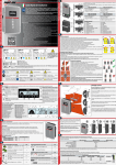
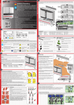
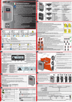
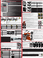
Labels and Symbols
1.
The labels on the inverter have the Agency marking, main technical data and identification of the equipment and manufacturer
®
®
®
Made in Italy
Made in Italy
AURORA
®
MODEL:
PHOTOVOLTAIC INVERTER
VDC max
VDC MPP
VDC, Full Power
I DC max
I SC max
-25 to + 60 °C
-13 to +140 °F
1000 V
200 - 950 V
320 - 800 V
18.9 A
24 A
DIN V VDE 0126-1-1
PROTECTIVE CLASS: I
TRIO-5.8-TL-OUTD-X-400
AURORA
10 minutes
Power-One
-25 to + 60 °C
-13 to +140 °F
02
03
04
P/N:PPPPPPPPPPP
SN:SSSSSSSSSS
WK:WW/YY04
02
03
XXXXXXXXX Q1
1000 V
200 - 950 V
320 - 800 V
2 x 15 A
2 x 20 A
VDC max
VDC MPP
VDC, Full Power
I DC max
I SC max
01
TRIO-XX.X-XX-XXXX-XXX-XXX01
MODEL:
PHOTOVOLTAIC INVERTER
VAC nom
400 V 3Ø, 3W+N+PE
f nom
50 Hz
Pacr (cos φ= 1)
5800 W @ 50 °C amb.
±
Pacr (cos φ= 0.9) 5220 W @ 50 °C amb.
10 A
I AC max
IP65
®
POW
ER
DC
ALA
AC
RM
GFI
03
ESC
UP
DOW
N
ENT
ER
TRIO
04
09
05
11
12
AURORA
TRIO-7.5-TL-OUTD-X-400
®
MODEL:
PHOTOVOLTAIC INVERTER
VAC nom
400 V 3Ø, 3W+N+PE
f nom
50 Hz
Pacr (cos φ= 1)
7500 W @ 50 °C amb.
Pacr (cos φ= ± 0.9) 6750 W @ 50 °C amb.
12.5 A
I AC max
VDC max
VDC MPP
VDC, Full Power
I DC max
I SC max
IP65
-25 to + 60 °C
-13 to +140 °F
10 minutes
14
1000 V
200 - 950 V
320 - 800 V
2 x 15 A
2 x 20 A
VAC nom
400 V 3Ø, 3W+N+PE
f nom
50 Hz
Pacr (cos φ= 1)
8500 W @ 50 °C amb.
Pacr (cos φ= ± 0.9) 7650 W @ 50 °C amb.
14.5 A
I AC max
DC
POWER
GFI
ESC
UP
DC
AC
DOWN
ENTER
POWER
AC
ENTER
DOWN
UP
15
16
17
18
19
20
ALARM
b17
b10
TRIO-20.0-TL-OUTD & TRIO-27.6-TL-OUTD
TRIO-20.0-27
.6-TL-OUTDQuick
Installation
Oltre
a quanto
sicurezza
Guide
di seguito
IT RevA
ed installazione
power-one.
esposto
condizioni
com.
riportateè obbligatorio
di garanzia
nel manualeleggere
La tecnologia
si intendono
e rispettare
di installazion
probabilmen di
inoltre
le informazioni
questo
valide
te gli
inverter
e disponibile di
se il Cliente
inverter
deriva
trifase
dal perfezionam
sul sito
rispetta
più utilizzati
quanto
www.
descritto
realizzare
al mondo ento
dei
nelmanuale.
STICHE impianti
nonché modelli
Convertitore
i primi
AURORA
di grandi
a conseguire PVI-10.0
di potenza
dimensioni
imigliori
e
senza
con orientament
risultati 12.5 che
condensator
Unità
in
sono
di conversione
i elettrolitici
o variabile.
sul campo
DC/AC
per aumentare
con topologia
Doppia
ulteriorment
sezione
dell’energia
di ponte
di
e la durata
trifase
Ampio
anche ingresso
di vita
Scatolaintervallo nel caso con inseguimento
e
di stringhe
di tensione
di cablaggio
orientate MPP
rimovibilein ingresso
indipendente
agli standard
in direzioni
per una
Algoritmo internaziona
diverse , consente
facile
raccolta di MPPT
una ottimale
installazione
di energia veloce li (versioni
raccolta
e preciso -S2, -S2F
una
per l’i
e -S2X)
prestazione
nseguimento
Costruzione
costante
della
Possibilità da
potenza
esterno e stabile
intempo
di
per uso nell’intero
• Possibilità gestire direttamente
realee
in qualsiasi intervallo
peruna
• Uscita
migliore
di connessione
da displaycondizionedi tensione
ausiliaria
in ingresso
la potenza ambientale
DC (24V, di sensori
e di potenza
attiva
300mA) esterni
e le regolazioni
per il
in uscita
monitoraggi
di potenza
reattiva
o delle
condizioni
ambientali
Guida
Etichette e Simboli
®
AURORA
PHOTOVOLTA
-25to+
60°C
-13to+14
0°F
TRIO
®
IC INVERTER
VDC
max
VDC
MPP
VDC,
Full
I DC max Power
I SC max
1000
V
200
440 950 V
- 800
2 x 25 V
2 x 30 A
A
IP65
N10606
MODEL:
TRIO-20.0-TL-O
Made
in Italy
DIN
V VDE
PROTECTIVE
0126-1-1
CLASS:
UTD-XXX-400I
VAC
nom
f nom
400
PAC nom
V 3Ø,
3W+N+PE
PAC nom (cosφ= 1)
50
I AC max (cosφ= ±0.9) 22000 W Hz
20000 @ 45
W @ °C amb.
45
33 A °C amb.
In caso
AURORA
PHOTOVOLTA
VDC
max
VDC
MPP
VDC,
Full
I DC max Power
I SC max
®
TRIO
®
IC INVERTER
1000
V
200
500 950 V
- 800
N10606
MODEL:
TRIO-27.6-TL-O
Made
Power-One
in Italy
DIN
V VDE
PROTECTIVE
0126-1-1
CLASS:
UTD-XXX-400I
TRIO-XX.X-XXXXXX-XXX-XXX
di richiesta
2 x 32 V
f
10minutes
2 x 40 A
400
P
01
V 3Ø,
A
della
3W+N+PE
P
φ
-25to+60°C
password
30000 50 Hz
-13to+14
φ
I
IP65
P/N:PPPPPPPP
0°F
27600 W @ 45
diservizio
W @ °C amb.
e/o in
02
45
45 A °C amb.
PPP
ilcampo
alcuni
SN:SSSSSSSSS
casi sull’apparecc
SN(serial
Obbligo
03
01
number)
Modello
S WK:WW/YY
di consultazion
del manuale
dautilizzare
02
XXXXXXXXX
hiatura,
di inverter
Part
10minutes
04
Number
03
èriportato
le zone
Q1
Serial
e
di
nell’etic
04
Numberdell’inverter
Settimana/An
hettaapplicata
Pericolo pericolo
dell’inverter
o
sullaparte
tante generico attenzione
no di
superiore
produzione
rezza informazione- Impor vengono
(inverter)
indicate
di sicu con
segnaletica,
Intervallo
Tensione
di temperature
etichette,
pericolosa
simboli
Obbligo
o icone.
gliamentodi utilizzare
Senza
nali di
e/o i
l’
mentotrasformator
mezzi abbiParti
protezione
e di isola
calde
persoPunto
Rispettivam
messa di collegament
a terra
continua ente
o della
di protezione
e alternata corrente
Tempo
di scarica
immagazzin
dell’energia
ata
Sul manuale
VAC
nom
nom
AC nom
(cos
AC nom
= 1)
(cos
AC max
=±0.9)
POWER
15cm
UP
AC
DOWN
DC
DC
AC
DC
AC
AC
ENTER
POWER
ALARM
GFI
ESC
UP
DOWN
ENTER
POWER
POWER
ALARM
GFI
ESC
UP
TRIO
ALARM
ESC
GFI
UP
DOWN
ENTER
POWER
ALARM
GFI
TRIO
ESC
UP
DOWN
ENTER
TRIO
AC
DOWN
ENTER
DC
POWER
ALARM
GFI
ESC
UP
DC
AC
DOWN
ENTER
POWER
ALARM
GFI
ESC
UP
AC
DOWN
ENTER
TRIO
TRIO
TRIO
AC
UP
ALARM
GFI
UP
ESC
AC
DOWN
GFI
ALARM
DC
POWER
ENTER
15cm
TRIO
50
cm
ALARM
GFI
ESC
UP
DC
AC
DOWN
ENTER
POWER
ALARM
GFI
ESC
UP
O
DC
ENTER
GFI
ESC
UP
AC
DOWN
ENTER
POWER
ALARM
GFI
ESC
UP
ALARM
GFI
ESC
UP
DC
AC
DOWN
ENTER
POWER
TRIO
ALARM
GFI
ESC
UP
AC
DOWN
ENTER
TRIO
AC
DOWN
ENTER
DC
TRIO
AC
DC
TRIO
POWER
ALARM
GFI
ESC
UP
DOWN
POWER
ENTER
15cm
Final installation of the inverter must not compromise access to15cm
any disconnection
devices
that may be located externally.
Please refer to the warranty terms and conditions available on the www.power-one.com
website and evaluate any possible exclusion due to improper installation. 50
cm
ALARM
GFI
ESC
UP
DC
AC
DOWN
ENTER
POWER
ALARM
GFI
TRIO
ESC
AC
DOWN
UP
ENTER
TRIO
TRIO
DC
POWER
ALARM
GFI
ESC
TRIO
UP
DC
AC
DOWN
ENTER
POWER
ALARM
GFI
ESC
UP
AC
DOWN
ENTER
DC
TRIO
POWER
ALARM
GFI
ESC
UP
DC
AC
DOWN
ENTER
POWER
TRIO
ALARM
GFI
ESC
UP
AC
DOWN
ENTER
TRIO
Wall mounting
6 x Ø 10 mm
Assembly Instruction
DC
POWER
TRIO
AC
DOWN
ALARM
7.
A1
During installation do not place the inverter
04 facing towards the ground.
• Position the bracket
template.
13
10
with the front cover
perfectly level on the wall and use it as a drilling
• Drill the 4 holes required using a drill with 10mm bit. The holes must be
about 70mm deep.
A2
• Fix the bracket to the wall with the 4 wall anchors, 10mm in diameter,
supplied.
• Attach the inverter by inserting the two tabs on the bracket
2 slots on the inverter (figures A1 and A2).
b23
13
into the
DC
ALAR
AC
GFI
UP
DOWN
ENTER
TRIO
A3
b19
• Secure the inverter to the bracket by screwing the 2 lock screws
on both sides of the inverter (figure A3).
14
AC
b15
b18
b21
b22
b20
b16
b14
R
DC
ALAR
M
AC
GFI
ESC
UP
DOWN
The front cover can be easily opened by sliding it over the
two rails on both inner sides of the inverter, as described in
the procedure below:
1
• Unscrew the 8 screws that secure the front cover 04 (step 1)
• Open the cover by pulling it towards you, then push it
upwards from both sides (steps 2 and 3).
At this stage, avoid misplacing the cover.
POW
ER
ALA
RM
2
3
4
DC
AC
GFI
ESC
UP
DOW
N
ENT
ER
TRIO
• Secure the cover open by pushing it forwards and then
downwards (steps 4 and 5)
9.
Quantity
4+4
Quick Installation Guide
1
di protezione
parecchiatur
dell’ap
a
Polo
positivo
vo della
e polo
(DC) tensione negati
di ingresso-
Additional components for 7.5 / 8.5kW models
Quantity
Two-hole gasket for M25 signal cable glands and
cap
2+2
Jumpers for configuration of the parallel
input channels
Two-hole gasket for M20 signal cable glands and
cap
1+1
Additional components for models with disconnect switch (-S)
TRIO-20.0-TL-OUTD&&TRIO-27.6-TL-OUTD
TRIO-27.6-TL-OUTD
TRIO-20.0-TL-OUTD
TRIO-20.0-27
TRIO-20.0-27
.6-TL-OUTD-Q
.6-TL-OUTD-Q
uick
uickInstallation
Oltre
Installation
Oltre a quanto
a quanto
sicurezza
Guide
sicurezza
GuideIT
di
di seguito
ed
power-one.
ITRevA
seguito
RevA
edinstallazione
power-one.
installazioneesposto
esposto
condizioni
com.
condizioni
è obbligatorio
com.
riportate
riportateè obbligatorio
di
digaranzia
nel
garanzia
leggere
nelmanuale
La
sisiintendono
manualeleggeree rispettare
Latecnologia
tecnologia
intendono
e rispettare
di
probabilmen
diinstallazion
probabilmen di
inoltre
installazion leleinformazioni
diquesto
inoltrevalide
questoinverter
informazioni
te
eedisponibile
validese
te gli
inverter
gli inverter
disponibiledidi
seililCliente
invertertrifasederiva
deriva
Clienterispetta
sul
trifasepiù dal
che
dalperfezionam
sulsito
rispettaquanto
chevogliono
perfezionam
sitowww.
piùutilizzati
quantodescritto
vogliono
www.
utilizzati
CARATTERI
alalmondo ento
CARATTERI realizzare
descrittonel
entodei
realizzare
mondononché
•• Convertitore
manuale.
deimodelli
STICHE
modelliAURORA nelmanuale.
STICHE impianti
nonchéi primi
impianti
Convertitore
di
i primia conseguire
AURORA
digrandi
grandidimensioni
di
a conseguire PVI-10.0
••
dipotenza
PVI-10.0
potenza
dimensioni
iimigliori
senza
miglioririsultati ee12.5
con
•• Unità
senzacondensator
conorientament
risultatiin 12.5che
chesono
condensator
orientament
in
•• Unitàdi
sono
diconversione
iielettrolitici
oovariabile.
conversione
elettrolitici
variabile.
sul
DC/AC
per
sulcampo
DC/ACcon
peraumentare
•• Doppia
campo
aumentare
contopologia
Doppia
topologia
ulteriorment
sezione
ulteriorment
dell’energia
di
sezione
dell’energia
diponte
•• Ampio
pontetrifase
di
eela durata
di ingresso
anche
trifase
la durata
Ampiointervallo
anche ingresso con
•• Scatola
di
intervallo nel
nelcaso
con inseguimento
divita
vitaee
casodi stringhe
inseguimento
•• Scatoladi cablaggio
di
di stringhe
di tensione
di cablaggio
tensione
orientate
in
MPP indipendente
orientate MPP
rimovibile
agli
rimovibileiningresso
indipendente
aglistandard
inindirezioni
ingresso
•• Algoritmo
standard
per
direzioni
, consente
peruna
Algoritmo internaziona
diverse
internaziona
unafacile
diverse , consente una
raccolta di
diMPPT
li (versioni facileinstallazione
una ottimale
MPPT
•• raccoltadi energia
installazione
ottimale raccolta
(versioni
di energia veloce
veloceelipreciso
raccolta
e precisoper-S2,
-S2,-S2F
una
-S2Fe -S2X)
unaprestazione
perl’l’iinseguimento
•• Costruzione
e -S2X)
prestazione
nseguimento
Costruzione costante
•• Possibilità
della
costante
dellapotenza
Possibilità da
daesterno e stabile
potenzain
di esterno pere stabilenell’intero
intempo
temporeale
nell’intero
per uso
•• Possibilità di gestire
gestire direttamente
uso in
realeeeperuna
intervallo
Possibilità
direttamente
inqualsiasi
perunamigliore
•• Uscita
qualsiasi intervallo
di
di
migliore
condizione
da
Uscitaausiliaria
diconnessione
condizioneditensione
connessione
da display
tensione
display la
ausiliaria
ininingresso
ambientale
di
DC
ambientale
la potenza
ingresso
potenzaattiva
disensori
DC(24V,
sensori
eedi potenza
(24V,300mA)
attivae le
di potenza
300mA) esterni
esterniper
regolazioni
ininuscita
perililmonitoraggie le regolazionidi
uscita
monitoraggi
dipotenza
potenzareattiva
oodelle
dellecondizioni reattiva
condizioni
ambientali
ambientali
AURORA
Guida
Guida
1.
1.
tichetteeeSimboli
Simboli
EEtichette
1+1
Quantity
2 (5.8 kW)
4 (7.5 / 8.5 kW)
Female quick fit connectors
®
®
AURORA
AURORA
PHOTOVOLTA
PHOTOVOLTA
TRIO®
®
ICTRIO
IC INVERTER
VDC
INVERTER
V max
DC
VDC
max
MPP
DC
VVDC,
MPP
VDC,Full Power
I DC
Full
max
Power
IISCDCmax
max
I SC max
-25to+
-2
-1
5to+60°C
3to+14
60°C
-13to+14
0°F
0°F
1000
2001000V
200- 950V V
440
- 950
440- 800
V
2 x -25
800V
V
22xx30
25A
2 x 30AA
A
IP65
IP65
MODEL:
N10606
N10606
Made
MODEL:
DIN Madein Italy
TRIO-20.0-TL-O
V
DIN VDEin0126-1-1
TRIO-20.0-TL-O PROTECTIVE
V VDE Italy
PROTECTIVE
0126-1-1
CLASS:
UTD-XXX-400
CLASS:I
VAC
UTD-XXX-400I
nom
AC nom
fVnom
400
nom
PfAC
nom
400V 3Ø, 3W+N+PE
(cos
V 3Ø,
PPACACnom
nom φ = 1)
(cos
(cos
φ = 1) 22000 50 3W+N+PE
Hz
IPACACmax
nom φ= ±0.9)
22000W 50
@ Hz
I AC max (cosφ= ±0.9) 20000
W @45 °C amb.
20000W
@ 45 °C
W @45 °C
amb.
33 A45 °Camb.
33 A amb.
Rapid
Rapida
a di
di instal
installazion
lazion
ee
®
®
AURORA
PHOTOVOLTA
PHOTOVOLTA
TRIO®
®
ICTRIO
IC INVERTER
VDC
INVERTER
V max
DC
VDC
max
MPP
DC
VVDC,
MPP
VDC,Full Power
I DC
Full
max
1000
2001000V
MODEL:
N10606
N10606
Made
MODEL:
DIN Madein Italy
TRIO-27.6-TL-O
V
DIN VDEin0126-1-1
TRIO-27.6-TL-O PROTECTIVE
V VDE Italy
Power-One
Power-One
TRIO-XX.X-XXTRIO-XX.X-XX-
200- 950V V
II
In
UTD-XXX-400
500
- 950
XXXX-XXX-XXX
I
Incaso
V
UTD-XXX-400
500- 800
V
casodi richiesta
XXXX-XXX-XXX
2 x -32
800V
fV
10minutes
V
di richiesta
22xx40
32A
400
10minutes
Pf
01
2 x 40AA
400V 3Ø, 3W+N+PE
della
01
V 3Ø,
PP
φ
A
-25to+60°C
dellapassword
30000 50 3W+N+PE
-2
Hz
-1
5to+60°C
φφ
IP
3to+14
IP65
password
30000W 50
P/N:PPPPPPPP
@ Hz
-13to+14
φ
I
0°F
27600
IP65
W @45 °C amb.
didiservizio
P/N:PPPPPPPP
0°F
27600W
@ 45 °C
e/o
02
W @45 °C
amb.
servizioilcampo
e/oin
45 A45 °Camb.
02 PPP
inalcuni
45 A amb.
PPP SN:SSSSSSSSS
ilcampoSN
alcunicasi
SN:SSSSSSSSS
Obbligo
03
casisull’apparecc
SN(serial
Obbligo
01
(serialnumber)
03 S
sull’apparecc
01 Modello
number)da
di
del
S WK:WW/YY
02 Modello di
XXXXXXXXX
WK:WW/YY
di consultazion
delmanuale
hiatura,
dautilizzare
02 Part
XXXXXXXXX
10minutes
04
manuale
consultazion
hiatura,le
utilizzareèriportato
di inverter
inverter
10minutes
04
03 Part Number
Q1
03 SerialNumber
èriportatonell’
le zone
ee
dell’inverter
zonedi pericolo
Q1
04 Serial Number
di
nell’eti
04 Settimana/An
Pericolo
Numberdell’inverter
eticchetta
Settimana/An
hettaapplicata
Pericolo pericoloo attenzione
dell’inverter
di
applicatasulla
parecchiatur
di protezione
generico
tante
protezione
nodell’inverter
parecchiatur
genericoo attenzionevengono
sullaparte
tante informazione
no didi produzione
partesuperiore
dell’ap
superiore(inverte
aa
rezza
produzione
dell’ap rezza informazione- Impor
Impor - vengonoindicate
(inverter)r)
Polo
Polo positivo
indicatecon
di
di sicu
positivo
vo
sicu con
ee polo
vodella
dellatensione
segnaletica,
Intervallo
polo
(DC)
segnaletica,
Intervallo
negati (DC) tensionedi negati
Tensione
di
Tensione
etichette,
diingresso
ditemperature
etichette,
ingressotemperature
pericolosa
pericolosa
simboli
Obbligo
simbolio
Obbligo
di
gliamento
oicone.
icone.
Senza
gliamentodi utilizzare
utilizzare
Senzatrasformator
nali
e/o
mento
nalidi
e/oii mezzil’l’ abbiParti
mentotrasformator
abbidiprotezione
mezzipersoParticalde
eedi isola
protezione
calde
persodi isolaPunto
Puntodi
Rispettivam
collegament
messa
Rispettivam
messaadi collegament
continua
oodella
aterra
terradi protezione
continua ente
ente
della
di protezione
eealternata
alternata corrente
corrente
Tempo
Tempo di
immagazzin
di scarica
immagazzin
scarica dell’energia
dell’energia
ata
ata
DC
max
SC max
SC max
Sul
Sulmanuale
manuale
IP65
IP65 Grado
Grado
Power
AC nom
AC nom
nom
nom
AC nom
AC nom(cos
AC nom
=
(cos 1)
AC nom(cos = 1)
AC
max (cos =±0.9)
AC max
=±0.9)
PROTECTIVE0126-1-1
CLASS:
CLASS:I
I
5
ENTE
R
TRIO
IP65 Grado
Male quick fit connectors
8.
Opening the cover
POWE
Rapid
a di instal
lazion
e
•
DC
ENTER
ESC
DC
Bolts and screws for wall mounting
•
GFI
TRIO
AC
DOWN
ALARM
• Unscrew the 8 screws and open the front cover 04 as described in the following paragraph to make all necessary connections. The cover is fitted
into fixed rails and cannot be removed.
Components available for all models
che vogliono
CARATTERI
POWER
TRI
ESC
6.
•
ENTER
POWER
M
Lifting points n°#
4
4
4
•
DC
AC
DOWN
ESC
TRIO
R
Unpacking and checking
The components of the packaging must be disposed on in accordance with the regulations in force in the country of installation.
When you open the package, check that the equipment is undamaged and make sure all the components are present.
If you find any defects or damage, stop unpacking and consult the carrier, and also promptly inform the Service Power-One.
•
•
•
UP
ENTER
POWER
POWE
Lifting
Where indicated and/or where there is a provision, eyebolts or handles, which can be used as anchorage points, are inserted and/
or can be inserted.
The ropes and means used for lifting must be suitable for bearing the weight of the equipment.
•
•
•
UP
ESC
DOWN
50
cm
Transport and handling
Transport of the equipment, especially by road, must be carried out with by suitable ways and means for protecting the
components (in particular, the electronic components) from violent shocks, humidity, vibration, etc.
•
•
ESC
GFI
DC
ESC
GFI
Hot surfaces
5.
1.
GFI
DC
LEDs and BUTTONS, in various combinations, can be used to view the status or carry out complex actions that are described more fully in the manual.
It is used to access the main menu, to go
ESC back to the previous menu or to go back to
GREEN On if the inverter is working
POWER
the previous digit to be edited.
correctly. Flashes when checking the
LED
grid or if there is insufficient sunlight.
It is used to scroll up the menu options or to
UP
shift the numerical scale in ascending order.
YELLOW The inverter has detected an
DC
ALARM
AC
It is used to scroll down the menu options or
anomaly. The anomaly is shown on the
LED
DOWN to shift the numerical scale in descending ordisplay.
der.
POWER
ALARM
GFI
ESC
UP
DOWN
ENTER
It can be used to conrm an action, to access
RED Ground fault on the DC side of
the submenu for the selected option (indicaGFI
02
01
03
ENTER
the PV generator. The error is shown
ted by the > symbol) or to switch to the next
LED
on the display.
digit to be edited.
2
ALARM
ALARM
TRIO
TRIO
DC
2 (5.8 kW)
4 (7.5 / 8.5 kW)
Line cable and protection devices
Instruments
ALARM
TRIO
Hazardous voltage
The operating parameters of the equipment are displayed through the display 01 : warnings, alarms, channels, voltages, etc.
Description of symbols and display fields.
b13 Daily energy produced
b1 RS485 data transmission
b2
b4
b6
b8
b14 PV voltage > Vstart
b2 RS485 line present
b1
b3
b5 b7
b9
b15 DC voltage value
b3 Radio line present.
b16 DC current value
b4 Bluetooth line present (*)
b17 DC/DC circuit part
b5 WiFi line present (*)
b18 DC/AC circuit part
b6 Warning
b19 AC voltage value
b7 Temperature derating
b20 AC current value
b8 Instantaneous power
b21 Connection to the grid
b9 MPP scan running
b13
b11
b22 Grid status
b10 Graphic display
b12
b23 Cyclic view on/off
b11 Power graph
(*) NOT available
b12 Total energy
Lifting and transport
14
• Install on a wall or strong structure suitable for bearing the weight
• Install in safe, easy to reach places
• If possible, install at eye-level so that the display and status LEDs can be seen easily
• Install at a height that considers the heaviness of the equipment
• Install vertically with a maximum inclination of +/- 5°
• To carry out maintenance of the hardware and software of the equipment, remove the covers
on the front. Check that there are the correct safety distances for the installation that will allow
the normal control and maintenance operations to be carried out
• Comply with the indicated minimum distances
50
• For a multiple installation, position the inverters side by side
cm
• If the space available does not allow this arrangement, position the inverters in a staggered
arrangement as shown in the figure so that heat dissipation is not affected by other inverters
POWER
4.
List of supplied components
20
13
Handles
Heat sink
Bracket
Locking screw
AC cable gland
Service cable glands
Anticondensation valve
DC cable glands
Input connectors (MPPT1)
Input connectors (MPPT2)
• Consult the technical data to check the environmental parameters to be observed • Installation of the unit in a location exposed to direct sunlight must be avoided as it may cause:
- power limitation phenomena in the inverter (with a resulting decreased energy production by the system)
- premature wear of the electrical/electromechanical components
- premature wear of the mechanical components (gaskets) and of the user interface (display)
• Do not install in small closed rooms where air cannot circulate freely
• To avoid overheating, always make sure the flow of air around the inverter is not blocked
• Do not install in places where gases or flammable substances may be present
• Do not install in rooms where people live or where the prolonged presence of people or animals is expected, because of the
noise (about 50dB(A) at 1 m) that the inverter makes during operation
• Avoid electromagnetic interference that can compromise the correct operation of electronic equipment, with consequent
situations of danger.
DC
Time need to discharge stored
energy
1+2
19
15
12
Environmental checks
TRIO
Point of connection for grounding protection.
Bracket for wall mounting+ Locking screw
16
11
Installation position
Always use safety clothing
and/or personal safety devices
1
Main components
01
Display
02
LED panel
03
Keypad
04
Front cover
05
AC output board
06
Communication and control board
07
Scheda di ingresso DC
08
DC disconnect switch
09
bracket mounting slot
10
Inverter
On account of the rarefaction of the air (at high altitudes), particular conditions may occur:
• Less efficient cooling and therefore a greater likelihood of the device going into derating because of high internal temperatures
• Reduction in the dielectric resistance of the air that, in the presence of high operating voltages (DC input), can create electric
arcs (discharges) that can reach the point of damaging the inverter
All installations at altitudes of over 2000 metres must be assessed case by case with the Power-One Service department..
10 minutes
Positive pole and negative
pole of the input voltage (DC)
L-key, TORX TX25
08
TRIO-7.5-TL-OUTD-S-400
TRIO-8.5-TL-OUTD-S-400
• Number of input channels: 1
DC disconnect switch 08 : Yes
Input connectors: quick fit connectors (2 pairs)((2 pairs per channel)
Installations above 2000 metres
IP65
Without isolation transformer
2
15
3.
The labels attached to the
equipment must NOT be removed, damaged, dirtied,
hidden,etc...
TRIO-8.5-TL-OUTD-X-400
Temperature range
Connector for the connection of the communication and control signals
16
17
DIN V VDE 0126-1-1
PROTECTIVE CLASS: I
Direct and alternating currents, respectively
Connector for connecting the configurable
relay
18
17
POWER
General warning - Important
safety information
Quantity
19
13
Inverter model
Inverter Part Number
Inverter Serial Number
Week/Year of manufacture
Components available for all models
TRIO-7.5-TL-OUTD-400
TRIO-8.5-TL-OUTD-400
• Number of input channels: 1
• DC disconnect switch 08 : No
• Input connectors: screw terminal block
Made in Italy
DIN V VDE 0126-1-1
PROTECTIVE CLASS: I
Protection rating of
equipment
Mass weight
25 kg
28 kg
28 kg
15
I ON
17
DC
Equipment weight
Model
TRIO-5.8-TL-OUTD(-S)-400
TRIO-7.5-TL-OUTD(-S)-400
TRIO-8.5-TL-OUTD(-S)-400
16
0 OFF
08
In the manual and/or in some cases on the equipment, the danger or hazard zones are indicated with signs, labels, symbols or icons.
IP65
08
TRIO-5.8-TL-OUTD-S
07
If the service password is requested, use the serial number field -SN: SSSSSSSSSS- shown on the identification label
(affixed to the side)
Always refer to instruction
manual
15
17
10
06
16
The models of inverter to which this guide refers are available in 3 power ratings: 5.8 kW, 7.5 kW
e 8.5 kW.
For inverters of equal output power the variant between the various models is the presence or
lack thereof, of the DC disconnect switch 08 .
TRIO-5.8-TL-OUTD-400
TRIO-5.8-TL-OUTD-S-400
• Number of input channels: 1
• Number of input channels: 1
08
• DC disconnect switch : No
DC disconnect switch 08 : Yes
• Input connectors: screw terminal block
Input connectors: quick fit connectors (2 pairs)
TRIO-5.8-TL-OUTD
02
TRIO-7.5/8.5-TL-OUTD
This new generation three-phase inverter for domestic installations, is available in three power ratings: 5.8,
7.5 and 8.5 kW. The compact, transformerless TRIOs are the latest products in the Aurora family for their
performance, ease of use and installation, monitoring and control. The topology of the TRIO 20.0/27.6 inverters
has been redesigned to ensure that the TRIO 5.8/7.5/8.5 models also enjoy high conversion efficiency across
a wide range of input voltages, and the double MPPT gives maximum installation flexibility for an optimal
energy production (TRIO 7.5/8.5 models).
FEATURES
• High speed and precise MPPT algorithm for real time power tracking and improved energy harvesting
• Wide input voltage range
• Two independent MPPT channels for TRIO-7.5/8.5 allows optimal energy harvesting from two sub- arrays
oriented in different directions (one MPPT channel for TRIO-5.8)
• Flat efficiency curves ensure high efficiency at all output levels ensuring consistent and stable performance
across the entire input voltage and output power range
• Datalogger and smart grid functionalities integrated on expansion cards:
• PMU expansion card option, with external sensors inputs for monitoring environmental conditions
and additional RS-485 for Modbus protocol
• Ethernet expansion card option with integrated Web Server and remote monitoring capability via
Web Portal (Modbus/TCP supported)
• Remote inverter upgrade
• Reactive power management
• Availability of auxiliary DC output voltage (24V, 100mA)
• Natural convection cooling for maximum reliability
• Outdoor enclosure for unrestricted use under any environmental conditions (IP65)
• Sliding cover for the easiest installation and maintenance
• No compulsory maintenance is required
18
01
TRIO-7.5/8.5-TL-OUTD-S
In addition to what is explained below, the safety and installation information provided in
the installation manual must be read and followed. The technical documentation and the
interface and management software for the product are available at the website http://
www.power-one.com
The device must be used in the manner described in the manual. If this is not the case the
safety devices guaranteed by the inverter might be ineffective.
Inverter Models and Components
Quick Installation Guide
2.
Choice of installation location
TRIO-5.8-TL-OUTD-400 / TRIO-7.5-TL-OUTD-400 / TRIO-8.5-TL-OUTD-400
TRIO-5.8_7.5_8.5-TL-OUTD-Quick Installation Guide EN RevA
Load protection breaker (AC disconnect switch) and line cable sizing
To protect the AC connection line of the inverter, we recommend installing a device for protection against over current and leakage with the following characteristics:
TRIO-5.8-TL-OUTD
TRIO-7.5-TL-OUTD
TRIO-8.5-TL-OUTD
Type
Automatic circuit breaker with differential thermal magnetic protection
Voltage/Current rating
400V /16A
Magnetic protection characteristic
B/C
Number of poles
3/4
Type of differential protection
A/AC
Differential sensitivity
300mA
Power-One Italy S.p.A. declares that the Power-One AURORA transformerless inverters, in terms of their construction, do not inject continuous ground fault currents and therefore there is no requirement that the differential protection installed downstream of the inverter be type B in accordance with IEC 60755 / A 2.
Characteristics and sizing of the line cable
For the connection of the inverter to the grid, you can choose between a star connection (3 phases + neutral) and a delta connection (3 phases).
The cross-section of the AC line conductor must be sized in order to prevent unwanted disconnections of the inverter from the grid due to high impedance of the line that
connects the inverter to the power supply point
Cross-section of the line conductor (mm2)
Maximum length of the line conductor (m)
Max 10mm2
TRIO-5.8-TL-OUTD
TRIO-7.5-TL-OUTD
TRIO-8.5-TL-OUTD
4
55m
40m
35m
6
80m
60m
55m
10
135m
105m
90m
The values are calculated in nominal power conditions, taking into account:
1. a power loss of not more than 1% along the line. 2. copper cable, with EPR/XLPE insulation, laid in free air
13 ÷ 21 mm
Parallel channel configuration
07
This configuration uses the two input channels (MPPT)
connected in parallel. This requires the jumpers (supplied)
between the positive and negative poles of the two DC
input channels to be installed and the parallel channel
mode to be set in the relevant section of the SETTINGS
menu.
Input connection (DC)
11.
-S Version
Standard Version
07
07
Input Mode
PARALLEL
Check for correct polarity in the input strings and absence of any leakage to ground in the PV generator.
When exposed to sunlight, the PV panels supply DC direct voltage to the inverter.
The inside of the inverter may only be accessed after the equipment has been disconnected from the grid and from the photovoltaic generator.
The inverter is only to be used with photovoltaic units with ground insulated input poles unless accessories allowing grounding of the inputs have been installed. In this case it is compulsory to install an isolation transformer on the AC side of the system.
• Connection of inputs on the Standard models
The input connections on inverter models that are not equipped with
TRIO 5.8kW (1 MPPT)
TRIO 7.5/8.5kW (2 MPPT)
a DC disconnect switch can be made in 2 different modes, based on the number
of available input channels.
+ − − +
+ −
07
TRIO-5.8
TRIO-7.5
TRIO-8.5
07
No. of input channels
1
2
2
22
DC cable gland
2 x M25
For all inverter models the DC terminal block 23 can be connected by feeding 23
MPPT1
MPPT2
23
the cables inside the DC cable glands 18 . The cable gland accepts cables of 18
maximum diameter from 10 to 17 mm, while each terminal of the terminal block
18
accepts a cable with maximum cross-section of 16 mm2 (1.5 Nm tightening
torque).
Unscrew the cable gland, remove the cover, feed a cable of suitable cross-section and connect it to the terminals on the DC input terminal block.
Once the connection to the terminal block has been made, firmly screw the cable gland (7.5 Nm tightening torque) and check the tightness.
• Connection of inputs on models with disconnect switch
The string connections for inverter versions equipped with DC disconnect switch 08 use
TRIO 5.8kW (1 MPPT)
TRIO 7.5/8.5kW (2 MPPT)
quick fit connectors (multicontact or weidmuller), placed at the bottom of the mechanism.
The number of quick fit connectors changes based on the number of input channels.
Each input channel is normally equipped with two pairs of connectors for the connection of two strings.
TRIO-5.8
TRIO-7.5
TRIO-8.5
No. of input channels
1
2
No. of quick fit connectors
4 (2 pairs)
4 + 4 (2 pairs per MPPT)
Connect all the strings included in the system design and always check the tightness
of the connectors.
MPPT1
MPPT2
MPPT1
MPPT2
If some of the string inputs are left unused, check that all relevant connectors are covered
with caps and install caps where needed. This is necessary to ensure the tightness of the inverter and to avoid damaging the unused connectors so that they can
be ready for later use.
0 OFF
0 OFF
I ON
I ON
Connection of the communication and control signals
The 7.5 and 8.5 kW power inverter versions are equipped with two independent input channels (and therefore with double maximum power point tracker MPPT), which
can however be connected in parallel using a single MPPT..
Independent channel configuration (default configuration)
This configuration is factory-set and uses both input channels (MPPT) as independent. This requires the jumpers
Input Mode
(supplied) between the positive and negative poles of the two DC input channels not to be installed and the
INDEPENDENT
independent channel mode to be set in the relevant section of the SETTINGS menu.
13.
Output connection (AC)
R S T N G
Unscrew the cable gland, remove the cover, insert the cable of suitable cross-section and connect the conductors
(Neutral, R, S, T and Ground) to the terminals on the AC output terminal board 31 .
Be careful not to change round one of the phases with neutral!
Once the connection to the terminal board is complete, screw in the cable gland firmly (tightening torque 8.0Nm)
and check the tightness.
• Format the SD card using a “FAT32” File System
• Save the (.tib) update file on the SD Card. The file must not be compressed and/or nested inside folders.
• Turn the inverter off by physically disconnecting the AC and DC voltages, as well as any voltage connected to the multi-function relay,
then open the inverter front cover
• Insert the SD Card in the dedicated memory card housing 25 with the notched side facing down.
• Commission the inverter as per the procedure described in section 14 of this installation guide
• The inverter display prompts for confirmation to launch the update
The update procedure starts automatically. Do not operate the inverter in any way during the update process
• Once the procedure is completed, the display shows the update results
The accessories can be bought separately and installed directly by a qualified technician or by the installer.
For information on the installation, compatibility and use of the accessories, refer to the relevant part documentation.
PMU EXPANSION BOARD
ETHERNET EXPANSION BOARD
PVI-RADIOMODULE
NEGATIVE GROUNDING KIT
Added features:
Added features:
Added features:
Added features:
• PMU - Management of active/reactive power • Ethernet connection for:
• Wireless (radio) communication line for • Negative input grounding.
• 2 analogue and 1 PT100/ PT1000 inputs. - Local monitoring (internal webserver) data transmission to the PVI-DESKTOP Installation of the board is compulsory
• Analogue sensor power supply (24 V) - Remote monitoring (“Aurora Vision/Easy monitoring device.
if PV panels are used that require the
• RS485 (ModBus protocol)
View” portal)
connection to ground of the negative
• RS485 (Aurora protocol)
pole.
26
30
6
ER
UP
N
ENT
ER
2
5
C7
J2
C2
LAB1
U1
J4
C4
R23
R9
R12
R11
R10
R28
R27
C11
LED1
R3
U11
D1
R13
R24
C3
C5
U4
R19 C10 C9
Y1
L1
C1
R15
R14
J3
2
VR1
C31
23
1
C29
24
Q1
D3
On Field Setup
ENTER to START
R39
D6
16
15
TP14
R38
U7
U6
TP12 TP13
LED2
R16
LED3
U8
R13
LED1
C8
TP20
R18
TP18
R20
TP21
TP17
XTAL2
C9
C3
C6
C2
C5
C7
U3
LED5
R41
C33
U9
J1
1
L5
J2
U12
7
Ppk
PpkDay
XX.X°C
XX.X°C
XXXXXW
XXXXXW
VoutR
Vout avg
XXXV
XXXV
VoutS
Vout avg
XXXV
XXXV
VoutT
Vout avg
XXXV
XXXV
Table: Technical Data
Maximum DC Input Current (Idcmax) / for each MPPT (IMPPTmax)
Maximum Backfeed current (from AC to DC side)
Number of DC Inputs Pairs for each MPPT
DC Connection Type
Type of photovoltaic panels that can be connected at input according to IEC 61730
Input Protection
Reverse Polarity protection
Input Over Voltage Protection for each MPPT - Varistor
Maximum Input Short Circuit Current for each MPPT
Photovoltaic Array Isolation Control
DC Switch Rating for each MPPT (Version with DC Switch)
Output Side
AC Grid Connection Type
Rated AC Grid Voltage (Vac,r)
AC Voltage Range
Rated AC Power (Pacr @cosφ=1 )
Maximum Apparent Power (Smax)
Maximum AC Output Current (Iac,max)
Contributory fault current
Inrush Current
Maximum output fault current
Rated Output Frequency (fr)
Output Frequency Range (fmin...fmax)
Nominal Power Factor and adjustable range
Total Current Harmonic Distortion
AC Connection Type
Output Protection
Anti-Islanding Protection
Maximum AC Overcurrent Protection
Output Overvoltage Protection - Varistor
Operating Performance
Maximum Efficiency (ηmax)
Weighted Efficiency (EURO/CEC)
Feed In Power Threshold
Stand-by Consumption
Communication
Wired Local Monitoring
Remote Monitoring
Wireless Local Monitoring
User Interface
Environmental
Ambient Temperature Range
Relative Humidity
Noise Emission
Maximum Operating Altitude without Derating
Environmental pollution classification for external environment
Environmental Category
Physical
Environmental Protection Rating
Cooling
Overvoltage Category in accordance with IEC 62109-1
XXXXXW
Vin2
Iin2
XXXV
XX.XA
Vin1
Iin1
XXXV
XX.XA
IoutT
FoutT
XX.XA
XX.XXHz
IoutS
FoutS
XX.XA
XX.XXHz
IoutR
FoutR
XX.XA
XX.XXHz
VoutTR
XXXV
VoutST
XXXV
Table: Technical Data
Input Side
Absolute Maximum DC Input Voltage (Vmax,abs)
Start-up DC Input Voltage (Vstart)
Operating DC Input Voltage Range (Vdcmin...Vdcmax)
Rated DC Input Power (Pdcr)
Number of Independent MPPT
Maximum DC Input Power for each MPPT (PMPPTmax)
MPPT Input DC Voltage Range (VMPPTmin ... VMPPTmax) at Pacr
DC Input Voltage Range with Parallel Configuration of MPPT at Pacr
DC Power Limitation with Parallel Configuration of MPPT
DC Power Limitation for each MPPT with Independent Configuration of MPPT at
Pacr , max unbalance example
Firmware
Last 7 days
New PW
Country Select
Last month
Cash
Last 30 days
Time
Last 365 days
Language
XXXXXW
Pin1
VoutRS
Service
Press
ESC
User Period
*1
V Start
*3
Autotest
*2
PMU Board
Input mode
Remote ON/OFF
Power Reduction
Sleep Mode
UV Prot. Time
XXXV
Ethernet
Board
Pot.
Scheda
Reattiva
PMU
Alarm
5950 Wp
1
6050 W Linear Derating From MAX to Null
[800V≤VMPPT≤950V]
320…800 V
-
TRIO-7.5-TL-OUTD
TRIO-5.8-TL-OUTD
18.9 A
GRID=
Lang=
Weight
Mounting System
Safety
Safety Class
Isolation Level
Marking
Reactive Power
TRIO-7.5-TL-OUTD
TRIO-8.5-TL-OUTD
30 A / 15 A
30 A / 15 A
Negligible
2 ((-S Version)
Tool Free PV Connector WM / MC4 (Screw Terminal Block on Standard Version)
Classe A
24.0 A
13 A /1000 V
Yes, from limited current source
2
20.0 A
According to local standard
23 A / 800 V
20.0 A
Three phase 3W or 4W+PE
400 V
320...480 V (1)
5800 W
7500 W
8500 W
5800 VA
7500 VA
8500 VA
10.0 A
12.5 A
14.5 A
12.0 A
14.5 A
16.5 A
Negligible
<20Arms(100mS)
50 Hz / 60 Hz
47...53 Hz / 57…63 Hz (2)
>0.995, adj.±0.9
>0.995, adj.±0.9 with
>0.995,adj.±0.9 with
withPacr=5.22kW,
Pacr=6.75kW,
Pacr=8.00kW,
adj. ± 0.8 with max 5.8kVA
adj. ± 0.8 with max 7.5kVA
adj. ± 0.8 with max 8.5kVA
< 2%
Screw terminal block, maximum cross-section 10 mm2
Dimensions (H x W x D)
MPPT
10.5 A
According to local standard
12.0 A
4 plus gas arrester
15.0 A
97.4% / 32 W
98.0%
97.5% / 36 W
< 15 W
97.5% / 36 W
Ethernet card with webserver (opt.), PVI-USB-RS232_485 (opt.), PVI-DESKTOP (opt.)
Ethernet card (opt.), PVI-AEC-EVO (opt.), AURORA LOGGER (opt.)
PVI-DESKTOP (opt.) with PVI-RADIOMODULE (opt.)
Graphic display
-25...+60°C /-13...140°F con derating sopra i 50°C/122°F
0...100% condensing
< 45 db(A) @ 1 m
2000 m / 6560 ft
3
External
IP 65
Natural
II (DC input) III (AC output)
641mm x 429mm x 220mm / 25.2” x 16.9” x 8.7”
855mm x 429mm x 237mm / 33.7” x 16.9” x 9.3” with open front cover
25.0 kg / 55.1 lb
28.0 kg / 61.7 lb
28.0 kg / 61.7 lb
Wall bracket
1. The AC voltage range may vary depending on specific country grid standard
2. The Frequency range may vary depending on specific country grid standard
Remark. Features not specifically listed in the present data sheet are not included in the product
*1 Available only for grid standard CEI-021
*2 Available only with PMU board installed
*3 Available only with Ethernet board installed
TRIO-5.8-TL-OUTD
Input Mode
PARALLEL/INDEP
If the inverter signals any errors/warnings the messages and their codes will be indicated on the display 01 . This state will also cause switching of the multi-function
relay (set to alarm mode in the menu SETTINGS>Alarm) which activates any external signalling device that may be connected.
U1
U5
U4
L4
C24
R21
U10
R44
LED4
R40
COSp X.XXX
Tipo regolazione
Today
Time hh:mm
Date DD MMM YYYY
Check for updated Firmware versions on the www.power-one.com website
If an inverter Firmware update is required, follow the instructions later provided.
U2
R48
C27
C23
D7
R51
XXXXXW
Serial No.
ENTER
Once the guided configuration is completed, the inverter restarts to apply the parameter settings
• When the inverter has power, the first check performed is the one relating to the input voltage:
- If the DC input voltage is lower than the Vstart voltage (voltage required to begin the inverter’s grid connection) the b14 icon remains off and the “Waiting sun” message
is displayed b10.
- If the DC input voltage is higher than the Vstart voltage the b14 icon is displayed and the inverter goes to the next stage of the controls.
In both cases the voltage levels and input current are displayed in the b15 and b16 fields.
• The inverter performs a control of grid parameters. The b22 icon, which represents the grid distribution, can have different statuses:
- not present, if the mains voltage results as absent.
- flashing, if the mains voltage is present but outside the parameters dictated by the standard of the country of installation.
- turns on, if the mains voltage is present and within the parameters dictated by the standard of the country of installation. In this condition, the inverter starts the
sequence of grid connection.
If the input voltage and the grid voltage are within the inverter operating intervals, connection to the grid will commence. After the inverter is connected, the icons
on the whole line b21 will come on steady..
Once the connection sequence has been completed, the inverter starts to operate and indicates its correct operation by making a sound and by the green LED coming on steady on the LED panel 02 .
TP22 TP23 TP24
C
D5
R66
R65
R64
R63
R62
R47
Pout
Display Set.
Once the connection and the configuration of the inverter is completed, the front cover must be closed by tightening
The inverter commissioning procedure is as follows:
• Close the AC disconnect switch to supply the inverter with the grid voltage
Power-One
Initializing...
• Close the DC disconnect switch to supply the inverter with the photovoltaic generator voltage.
...............
Please Wait
If the inverter is equipped with a DC disconnect switch (-S models), turn the DC disconnect switch 14 to the ON position.
• When the inverter is connected to the power supply, the display will show a guided configuration procedure. Press ENTER to set the following:
-Inverter time and date
- Parallel or independent mode
- Selection of grid standard and
configuration of the input channels
corresponding display language
D2
C26
J3
S1
A
C30
R56
E-tot XXXXXXkWh
E-par XXXXXXkWh
Partial
Switch for setting the termination resistance of the RS485 (PC) line
14.
1
XXX.XkWh
XX.XEUR
Part No.
S2
IP65 the screws (2.4 Nm tightening torque) in the order shown.
7
R1
C1
R2
R3
R4
R5
R6
R7
R8
R9
E-day
$-day
Pin2
Address
a05
4
3
INFORMATION
Total
J4
Please refer to the manual for details of the connections and functions available on the control and communication board
password 0000
X.XM©
XmA
29
Terminal block for:
- PC RS485 serial connection (to connect local or remote
monitoring systems)
- Remote ON/OFF connection
- Tachometer signal (WIND version) connection
a04
DOW
02 . Section b10 consists of 2 lines with 16 characters
SETTINGS
Connector for radiomodule or Ethernet board installation
SLOT 2 - Connector for PMU board installation
RS485 (PC) communication card housing
AC
1
J1
K1
TP5
TP3
TP4
TP6
TP7
SN XXXXXX
Fw rel. XXXX
Tint
Tboost
Refer to the manual for details
regarding use and functions
available in the menu.
Riso
Ileak
Type OUTD
P/N -XXXX-
STATISTICS
XXXV
XXXV
J9
J3
A3
28
GFI
J13
U3
LED2
R4
LED3
R5
LED4
R6
C11
R22
R23
C12
R24
R10
R11
TP2 R12
C4
R17
Press ESC to access the three main menus,
which have the following functions:
• STATISTICS>Displays the statistics;
• SETTINGS>Modify the settings of the inverter
• INFO>View service messages for the operator;
Inverter OK
Date Time
Vbulk
Vbulk_m
1
DC
ALA
Structure of the main menu
(cycle view)
J7 e J11 Connection of the RS485 (PC) line on RJ45 connector
27
a05
4
C6
RT1
R2
R1
C12
D4
R28
R29
R30
R31
R32
R33
R34
C21
L1
L2
C13
R25
R26
R27
L3
C14
TP2
5
R67
R68
C15
R35
R36
R37
R15
8
R19
R14
C19
7
D1
C20
Viewing of the GENERAL INFORMATION is
cyclic. This information relates to the input
and output parameters and the inverter
identification parameters.
By pressing ENTER it is possible to lock scrolling
on a screen to be constantly displayed.
Pb-free
30
29
2
R7
R8
R52
R54
C36
C37
R45
2
1
C28
Structure of the display menu
a04
1
R22
R21
R20
C45
R46
C47
C35
C41
C8
has a section b10 (graphic display) for moving through the menu using the buttons of the LED panel
GENERAL INFORMATION
18.
R18
R17
R16
C43
R58
C44
R59
L3
R53
C25
C39
C22
01
XTA
C10
C34
C38
R49
R55
C48 R61
The display
per line:
R60
C32
C40
R57
LAB1
17.
Characteristics and technical data
a03
J2
26
28
J6
Componenti Accessori
16.
a02
Terminal block connecting to the configurable relay that allows connection of external devices which, according to the mode selected in
the menu SETTINGS>Alarm can, for example, signal malfunctions. The
operating modes that can be set are:
-Production -Alarm
-Alarm (configurable) -Crepuscolar
ESC
Characteristics and technical data
Firmware update
The firmware can be simply updated via the SD Card (4 GB maximum storage)
The most recent firmware version is available in the downloads section of the www.power-one.com Website or upon request to the Power-One Service.
Launch the update while in good irradiation conditions (avoid the dawn and dusk hours)
27
TRIO
15
15.
25
07
RM
31
R S T N G
a01
POW
05
1
Ref.
Ref.
Description
manual inverter
24
J14 SLOT 3 - Connector for WIFI modules installation (NOT ACTIVE)
a01
A2 Inverter data memory card housing
25
A1 SD CARD housing
a02
S2 Switch to set the inverter to normal or service mode
a03
BT1 Battery housing
24
1
12.
For the connection of the inverter to the grid, you can choose between a star connection (3 phases + neutral) and a delta connection (3 phases).
In any case, connection of the inverter to ground is mandatory.
To prevent electrocution hazards, all the connection operations must be carried out with the disconnect switch
downstream of the inverter (grid side) open and locked.
For all models, connection with the AC output terminal board 31 is made by inserting the cables in the AC cable gland 15 .
The maximum accepted cable cross-section ranges from 13 to 21 mm, whereas each individual terminal of the terminal board accepts
a cable with cross-section of up to 10 mm2 (tightening torque 1.5Nm).
The following table shows the main components and the connections available on the control and communication board.. Each cable that must be connected to the
communication card must go through the three service cable glands 16 .
8
Commissioning
Input configuration (DC)
10.
I
Transformerless (TL)
CE
TRIO-8.5-TL-OUTD
Service- Contact Details:
1000 V
350 V (adj. 200...500 V)
0.7 x Vstart...950 V
7650 Wp
2
8700 W
2
4800 W
4800 W
320…800 V
320…800 V
Linear Derating From MAX to Null [800V≤VMPPT≤950V]
4800 W [320V≤VMPPT≤800V] 4800 W [320V≤VMPPT≤800V]
the other channel: Pdcr-4800W the other channel: Pdcr-4800W
[215V≤VMPPT≤800V]
[290V≤VMPPT≤800V]
Australia
Benelux
China
Eastern Europe
France
Germany
Greece
India
Italy
Middle East
Singapore
Spain
South east Asia
UK
USA
+61 2 9735 3111
+32 2 206 0338
+8675529885888
+49 7641 95520 32
00 800 00 28 76 72
0800 2200211
00 800 00 28 76 72
+65 6896 3363
00 800 00 28 76 72
00 800 00 28 76 72
+65 6896 3363
00 800 00 28 76 72
0800 0232341
+1 877-261-1374
[email protected]
[email protected]
[email protected]
[email protected]
[email protected]
[email protected]
[email protected]
[email protected]
[email protected]
[email protected]
[email protected]
[email protected]
[email protected]
[email protected]
Italy Facility
Via S. Giorgio, 642
52028 Terranuova B.ni
Italy
+39 055 9195 1
Phoenix Facility
3201 East Harbour Drive
Phoenix, Arizona, 85034
United States
480-643-1700
Camarillo Facility
740 Calle Plano
Camarillo, California, 93012
United States
805-987-8741
http://www.power-one.com