1
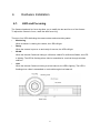
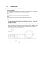
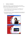
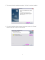
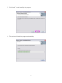
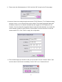
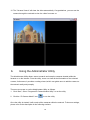
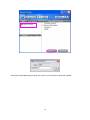
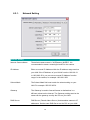
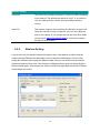
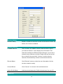
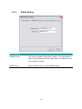
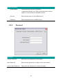
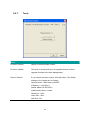
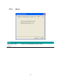
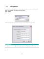
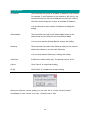
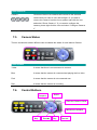
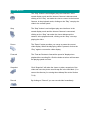
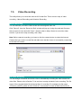
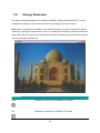
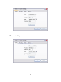
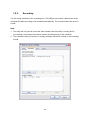
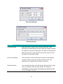
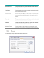
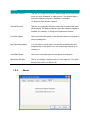
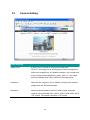
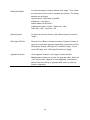
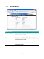
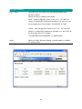
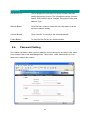
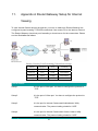
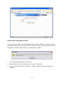
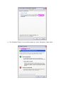
802.11g Wireless Internet Camera User Manual Version: 1.0 Released Date: Jan., 2005 Contents 1. 2. 3. 4. 5. 6. Introduction.......................................................................................................................1 Package Content.............................................................................................................1 System Requirement.......................................................................................................1 Hardware Installation ......................................................................................................2 4.1. LED and Focusing.............................................................................................. 2 4.2. Camera Ports ..................................................................................................... 3 4.3. Installation Pr ocedure......................................................................................... 4 Software Installation........................................................................................................5 Using the Administrator Utility......................................................................................10 6.1. General Setting..................................................................................................11 6.2. Detail Setting .................................................................................................... 12 6.2.1. Netw ork Setting ........................................................................................ 14 6.2.2. Wireless Setting........................................................................................ 15 6.2.3. E- Mail Setting ........................................................................................... 19 6.2.4. Resolution................................................................................................. 20 6.2.5. Advanced Setting ..................................................................................... 21 6.2.6. Passw ord.................................................................................................. 22 6.2.7. Tools ......................................................................................................... 23 6.2.8. About ........................................................................................................ 24 6.3. 7. Setting Wizard .................................................................................................. 25 Using the Camera Viewer............................................................................................27 7.1. Panel Introduction ............................................................................................ 27 7.2. Camera Buttons................................................................................................ 28 7.3. Camera Status .................................................................................................. 29 7.4. Control Buttons ................................................................................................. 29 7.5. Video Recording ............................................................................................... 31 7.6. Change Resolution........................................................................................... 32 7.7. View Four Cameras Simultaneously ................................................................ 33 7.8. View er Utility Setting ........................................................................................ 33 7.8.1. Setting....................................................................................................... 34 7.8.2. Recording ................................................................................................. 36 8. 9. 10. 11. 12. 7.8.3. Status ........................................................................................................ 38 7.8.4. General ..................................................................................................... 39 7.8.5. About ........................................................................................................ 40 7.9. Playback ........................................................................................................... 41 7.10. Rotate Video ..................................................................................................... 43 Web Connection and Setup.........................................................................................44 8.1. Camera Setting................................................................................................. 45 8.2. Netw ork Setting ................................................................................................ 46 8.3. Wireless Setting................................................................................................ 50 8.4. Passw ord Setting ............................................................................................. 53 Frequently Asked Questions........................................................................................55 Technical Specifications...............................................................................................56 Appendix A Router/Gateway Setup for Internet Viewing ........................................57 Appendix B Viewing via UPnP in Windows XP.........................................................59 1. Introduction Thank you for choosing the Internet Camera. This Internet Camera sends live video through 10/100Mbps w ired or 54Mbps 11g w ireless netw ork to a w eb browser or camera view er across Internet anyw here in the w orld! This compact, self-contained unit lets you keep an eye on your home, your kids, and your w orkplace—w hatever’s important to you. How does the Camera do all of this? Unlike standard “w eb cams” that require an attached PC, the Internet Camera can connect directly to a netw ork. The Motion JPEG video compression produces a high quality, high-frame rate, 640 x 480 video stream. The included Camera View er utility lets you record the video stream to your local hard drive, “live” or on a predetermined schedule. Use the instructions in this Guide to help you integrate the Camera into your netw ork. These instructions should be all you need to get the most out of the Internet Camera. 2. Package Content One Internet Camera One Antenna One Pow er Adapter One Camera Stand One 100M Category 5 Ethernet Cable One Quick Installation Guide One CD ( Including Manual/Utility/Driver) If any of the above items are missing, please contact your supplier. 3. System Requirement System requirement for PC, MAC or Notebook PC to access the Internet Camera are: OS System: Windows 98SE, Me, NT, 2000, XP, Server 2003 CPU: Intel Pentium III 750MHz above or Intel Celeron 1GHz above Memory Size: 128MB (256MB recommended) VGA Card Resolution: 800 x 600 or above 1 4. Hardware Installation 4.1. LED and Focusing The Camera head and its focus ring allow you to modify the aim and focus of the Camera. To adjust the Camera’s focus, rotate the dark focus ring. There are four LEDs indicating the camera status and netw orking status. y Monitoring When someone is view ing the camera, the LED w ill light. y Ready When the camera is pow er on and ready for access, the LED w ill light. y WLAN When the Internet Camera is linking to a Wireless LAN AP or a Wireless Station, the LED is lighting. The LED is flashing w hen video is transmitted or received through w ireless netw ork. y LAN When the Internet Camera is linking to w ired netw ork, the LED is lighting. The LED is flashing w hen video is transmitted or received through w ired netw ork. 2 4.2. Camera Ports The Camera features three ports and a Reset button. y Antenna Connector This round connection is standard Reverse SMA connector where any antennas w ith Reverse SMA connector can connect to the Internet Camera. y Power The Pow er port is where you can connect the pow er adapter. y LAN The LAN port is w here you can connect the Ethernet netw ork cable. y Reset 1. If problems occur w ith your Internet Camera, press the reset button w ith a pencil tip (for less than 2 seconds) and the Internet Camera w ill re-boot itself, keeping your original configurations. 2. If problems persist or you experience extreme problems or you forgot your password, press the reset button for longer than 5 seconds and the Internet Camera w ill reset itself to the factory default settings (warning: your original configurations w ill be replaced w ith the factory default settings). 3 4.3. Installation Procedure 1. Unpack the Internet Camera package and verify that all the items listed in the Chapter 2 are provided. 2. Connect the Internet Camera to your netw ork by attached the netw ork cable from the sw itch/router to the UTP port of the Internet Camera. 3. Connect the pow er adapter to the Internet Camera and plug the pow er adapter to pow er outlet. The Internet Camera w ill be pow ered on. When the Internet Camera is ready, the Ready LED w ill show orange color. Note: It is highly recommended to use the pow er adapter shipped w ith the Internet Camera, do NOT use any other pow er adapter from any sources. 4 5. Software Installation Follow the simple steps below to run the Install Wizard to guide you quickly through the Installation process. The follow ing installation is implemented in Window s XP. The installation procedures in Windows 98SE/Me/2000/Server 2003 are similar. 1. Insert the CD shipped along w ith the Internet Camera into your CD- ROM drive. The “Autorun.exe” program should be executed automatically. If not, run “Autorun.exe” manually from “Autorun” folder in the CD. 2. The Install Wizard w ill show four selections, select the program you w ant to install or click “Exit” to install the program later. The follow ing installation steps are the demonstration of “IC-1000/Wg” and “ Click To Setup”. 5 3. The system w ill start the installation procedures. Click “ Next” to continue installation. 4. If you w ish to install the softw are program in an alternate location, click “Change”; otherw ise click “Next” to move on to the next step. 6 5. Click “ Install” to start installing the program. 6. The system w ill install the program automatically. 7 7. Click “Finish” to complete the softw are installation. 8. When the installation is completed. The system w ill auto run ”Administrator Utility“. On the Internet Camera first page, the cameras found in the netw ork are listed in the left w indow . Choose the one you w ant to configure and click “Setting Wizard” to proceed. N IPCamera_MJPEG “N” means the camera is new and not configured. 8 9. Please enter the default passw ord “1234” and click “OK” to login to the IP setup page. 10. Internet Camera is w orking through the netw ork (TCP/IP Protocol). The IP address setting must be correct, or you cannot access to the camera. The w izard program w ill detect the IP address status of your network automatically and suggest a free IP address for the Camera. You can accept the suggested value or enter the value manually. If you enter the value manually, please be aw are that the “Subnet Mask” must be the same for both the camera and the PC. Click “Finish” to apply the configuration. 11. This w izard will pop up a w indow to ask you if you want to run the “Camera View er” and see the video of the Camera immediately. Select “OK” to run “ Camera View er”. 9 12. The “ Camera View er” w ill show the video automatically. Congratulations, you can use the camera through the netw ork to view the video from now on. 6. Using the Administrator Utility The Administrator Utility allow s users to search and setup the cameras located w ithin the Intranet or on the Internet. From the utility, users can view all the information of the selected camera; furthermore, it provides a setting w izard, which can guide users to add the camera to the netw ork easily and promptly. There are tw o ways to run the Administrator Utility as follows. 1. Click “Start”, select “ Programs\IP Camera\Admin Utility” to run the utility. 2. Click the “ IP Camera Admin” icon to run the utility. Once the utility is started, it w ill search all the cameras w ithin the netw ork. To do more settings, please refer to the description in the follow ing sections. 10 N IPCamera_MJPEG 6.1. General Setting LAN Auto Discover Click the button w ill search the camera w ithin the netw ork automatically. Camera List The list show s the camera name and the setup status of the camera. It means the camera is in the default setting. It means the camera is configured before. Internet Add Click “Add” w ill appear a w indow for you to enter the IP Address of the camera on the Internet. Delete Click “Delete” to delete the camera from the list. 11 Camera List The list show s the camera name and the connect status of the camera. It means the camera is disconnected or not in the Internet. It means the camera is connected. Inform ation of Camera Camera Information It displays all information of the selected camera. The information includes Firmw are Version, Netw ork Information, IP Address, UPnP Setting, DDNS Setting, Wireless Setting, Resolution and E- mail setting, etc. Camera Setting Detail Setting Click “Detail Setting” to do more setting of the camera such as IP address, Resolution, passw ord and firmw are upgrade, etc. Setting Wizard Click “Setting Wizard” to setup the necessary setting for the camera. 6.2. Detail Setting When you click the “ Detail Setting”, a screen w ill pop up for you to enter the “Administrator Name” and “ Passw ord”. The default value is as follow s. Name: “Adm in” Passw ord: “1234” 12 N IPCamera_MJPEG If the name and passw ord you enter are correct, you can start to setup the camera. 13 6.2.1. Network Setting Netw ork Setting Internet Camera Name The default camera name is “WIPCamera_MJPEG”. It is recommended to name a meaningful name for the camera. IP Address Enter an unused IP Address w ithin the IP address range used on your LAN. If the IP Address of your LAN is from the 192.168.2.1 to 192.168.2.254, you can set an unused IP Address from the range for the camera, for example: 192.168.2.250. Subnet Mask The Subnet Mask field must match the subnet setting on your LAN. For example: 255.255.255.0. Gatew ay The Gatew ay is used to forw ard frames to destinations in a different subnet on the Internet. The Gatew ay setting must be the same w ith the gatew ay used by the PCs on your LAN. DNS Server DNS Server (Domain Name Server) that translates names to IP addresses. Set the same DNS Server as the PCs on your LAN. 14 Netw ork Setting Video Port The Video Port is used to transmit or receive the video streaming in the netw ork. The default port setting is “4321”. If you w ant to view the video from the camera, the port setting should be correct. Web Port This camera support w eb connection, the default w eb port is 80. Since the w eb server may use port 80, you can use a different port for the camera. If you change the w eb port from 80 to 8080, you must type http://192.168.2.3:8080 to connect the camera through the w eb browser. 6.2.2. Wireless Setting If you w ant to use the Internet Camera through w ireless LAN, please set up the Internet Camera through Ethernet first and make sure your w ireless LAN setting is correct. After setting the w ireless LAN, unplug the Ethernet cable then you can start to use the Internet Camera through w ireless LAN. If the w ireless configuration does not w ork, please plug the Ethernet cable again, and configure the Internet Camera through Ethernet until the w ireless LAN settings are correct. 15 Wireless Setting Wireless Setting Enable or disable the w ireless function of the Internet Camera. By default, the function is disabled. Available Network Available Netw ork This list show s all available w ireless networks within range of your Internet Camera. It also displays the information of the netw orks including the SSID and Signal Strength. If you w ant to connect to any netw orks on the list, double-click the item on the list or select the item and click “ Connect”, and the Internet Camera w ill automatically connect to the selected netw ork. Refresh Button Click “Refresh” button to collect the new information of all the wireless networks nearby. Connect Button Click “Connect” to connect to the selected netw ork. Add to Profile Button Add the selected netw ork to Profile List and save it in your PC. Profile List 16 Profile List The “ Profiles List” is for you to manage the netw orks you connect to frequently. The profile list displays all the profiles and the relative settings of the profiles including Profile Name, SSID, Channel, etc. If you w ant to connect to any profiles on the list, double-click the profile or select the profile and click “Activate”, and the Internet Camera w ill automatically connect to the selected profile. Add/Delete/Edit Button Click these buttons to add/delete/edit the selected profiles. Activate Button Click “Activate” to connect to the selected profile. When a profile is activated, the card w ill be initially connected to the profile. Configure the Profile Profile Name Define a recognizable profile name for you to identify the different netw orks. SSID The SSID (up to 32 printable ASCII characters) is the unique name identified in a WLAN. The ID prevents the unintentional merging of tw o co-located WLANs. You may specify a SSID for the card and then only the device with the same SSID can interconnect to the card. If you w ant to add one of the netw orks nearby to the profile list, pull dow n the menu, all the netw orks nearby will be listed and you can add one of them to the profile list. Channel This setting is only available for Ad Hoc mode. Select the number of the radio channel used for the netw orking. The channel setting should be the same w ith the netw ork you are connecting to. Netw ork Type Infrastructure – This operation mode requires the presence of a Wireless LAN Access Point or Router. All communication is done via the Access Point or Router. Ad-Hoc – Select this mode if you w ant to connect to another wireless stations in the Wireless LAN netw ork w ithout through an Access Point or Router. Configure the Profile 17 Encryption Enable or disable the encryption function for the wireless data communications. Key Length You may select 64-bit or 128-bit to encrypt transmitted data. Larger key length w ill provide higher level of security, but the throughput w ill be low er. Key For mat Hexdecimal – Only “A-F“, “a-f“ and “0-9“ are allow ed to be set as WEP key. ASCII – Numerical values, characters or signs are allow ed to be WEP key. It is more recognizable for user. Default Key Select one of the keys (1~4) as the encryption key. Key1 ~ Key4 The WEP keys are used to encrypt data transmitted in the wireless network. Fill the text box by follow ing rules below . 64-bit – Input 10-digit Hex values (in the “A-F”, “a-f” and “0-9” range) or 5-digit ASCII characters (including “a-z” and “0-9”) as the encryption keys. For example: “0123456aef“ or “test1”. 128-bit – Input 26-digit Hex values (in the “A-F”, “a-f” and “0-9” range) or 13-digit ASCII characters (including “a-z” and “0-9”) as the encryption keys. For example: “01234567890123456789abcdef“ or “administrator”. Netw ork Inform ation Netw ork Information List This list show s the detailed netw ork information of the selected netw ork from the Available Netw ork list. The information including Netw ork Type, SSID, Channel, BSSID, Encryption Setting and Signal Strength. BSSID is the MAC Address of the w ir eless devices. 18 6.2.3. E-Mail Setting E-Mail Setting E- Mail Account This camera supports “Snap Shot” function. You can snapshot a picture and send the picture by E- Mail. Enter the E- Mail Account for receiving the picture. SMTP Server Enter the SMTP Server for the E-Mail sending. 19 6.2.4. Resolution Resolution Resolution Select the desired video resolution format. Larger resolution requires more bandw idth. 640 x 480 is “VGA” format. 320 x 240 is “CIF” format. 20 6.2.5. Advanced Setting Advanced Setting UPnP When the UPnP function is enabled, the camera can be detected by UPnP compliant system such as Windows XP. The camera will be displayed in the Neighborhood of Window s XP, so you can directly click the camera to view the video through w eb browser. DDNS Many internet connections use a "Dynamic IP address", w here the Internet IP address is allocated dynamically w henever the Internet connection is established. Internet users should know the IP Address of the camera w hen they w ant to connect to the camera every time. DDNS is designed to solve this problem, by allow ing users to connect to your LAN using a domain name, rather than an IP address. Enable/Disable Enable or disable DDNS function of the camera. Provider Several companies provide DDNS service. This camera supports the service from DynDNS w ho is one of the DDNS providers. 21 Advanced Setting Domain Name The domain name given by DynDNS is “registername.dyndns.com”. Enter the domain name that you register for the camera from DynDNS w eb site. Account Enter the login name for the DDNS service. Passw ord Enter the passw ord for the DDNS service. 6.2.6. Password Password Current Passw ord Enter the current password of the camera. New Passw ord Enter the new password you want to use for the camera. Confir m New Password Retype the new password to confirm the setting. 22 6.2.7. Tools Tools Fir mw are Version Display current firmw are version. Fir mw are Update The utility is not allow ed users to upgrade firmw are. Please upgrade firmw are in the Web Management. Reset to Default If you w ant to reset the camera, click this button. The default settings of the camera are as follow s. Camera Name: “WIPCamera_MJPEG” IP Address: “192.168.2.3” Subnet Mask: 255.255.255.0 Administrator Name: “Admin” Passw ord: “1234” Video Port: “4321” Web Port: “80” 23 6.2.8. About About Administrator Utility Display current Administrator Utility Version. Version 24 6.3. Setting Wizard When you click the “Setting Wizard”, a screen w ill pop up for you to enter the “Administrator Name” and “ Passw ord”. The default value is as follow s. Name: “Adm in” Passw ord: “1234” If the name and passw ord you enter are correct, you can start to setup the camera. Setting Wizard Internet Camera Name The default camera name is “WIPCamera_MJPEG”. It is recommended to enter a meaningful name for the camera. 25 Setting Wizard IP Address The w izard will auto setup an available IP Address to the camera. For example: if the IP address of the netw ork is 192.168.2.x, the wizard will search an unused IP Address from 192.168.2.250 to 192.168.2.0 and assign the camera an available IP Address. You are allow ed to enter another IP Address to change the setting. Subnet Mask The w izard will auto search the Subnet Mask setting of the netw ork and set the camera in the same Subnet Mask. You can enter another Subnet Mask to change the setting. Gatew ay The w izard will auto search the Gatew ay setting of the netw ork and set the camera to use the same Gatew ay. You can enter another Gatew ay to change the setting. Video Port It defines the video stream port. The default value is “4321”. Cancel Click “Cancel” to stop w iz ard setting. Finish Click “Finish” to complete the camera setting. When you finish the camera setting, you can click “Ok” to run the “ Camera View er” immediately or click “ Cancel” to run the “ Camera View er” later. 26 7. Using the Camera Viewer The Camera View er Utility allows users to view video from up to four cameras. It also allow s users to manual/schedule record video and playback the recording file. The status of camera view ing such as frame rate, video received, and etc. are also recorded in time. There are three w ays to run the Camera View er Utility as follows. 1. Click “Start”, select “ Programs\IP Camera\Camera View er” to run the utility. 2. Click the “ IP Camera View er” icon to run the utility. 3. Click “Setting Wizard” from Administrator Utility and follow the instructions in the utility. 7.1. Panel Introduction In the beginning w hen you start the Camera View er, you would see a Control Panel and a four division View er w indow. 27 7.2. Camera Buttons 28 Camera Buttons Click one of these four cameras w ill connect to the selected Camera camera that you w ant to view and configure. If you want to remove the camera from the view er, please right click the icon and select “Reset Camera x”. If you w ant to configure the camera, please right click the icon and select “ Configure Camera x”. 7.3. Camera Status There is a status bar show n different color to indicate the status of each Internet Camera. Camera Status Yellow It means that there is no camera set to connect. Blue It means that the camera is connected and playing the live video. Pink It means that the camera is not connected now. Red It means that the camera is recording. 7.4. Control Buttons Snapshot Pause Close the Camera View er Minimize the Window Stop Record 29 Play Forw ard Control Buttons Play The “ Play” button is an intelligent play user-interface. In the normal display mode and the Internet Camera is disconnected, clicking on the “ Play” can make the view er connect to the Internet Camera. In the playback mode, clicking on the “ Play” can play the video in the normal speed. Stop The “Stop” button is an intelligent play user-interface. In the normal display mode and the Internet Camera is connected, clicking on the “Stop” can make the view er disconnect the camera. In the playback mode, clicking on the “Stop” can stop playing the video. Pause The “ Pause” button provides you a w ay to pause the current video display. When the displaying video is paused, click on the “Play” again to resume the video display. Forw ard The “Forw ard” button to forw ard the speed of display when playback the recording file. Click the button at a time w ill increase the playing speed one time. Snapshot Click “Snapshot” w ill make the view er to take a snapshot of the video and save the picture as a bitmap file in the hard disk. (You can set the directory for storing these bitmap files at the Section 7.8.4) Record By clicking on “ Record” you can record video immediately. 30 7.5. Video Recording This utility allow s you record the video in AVI format files. There are tw o ways of video recording – Manual Recording and Schedule Recording. Manual Recording You can manually record the video stream into an assigned video file. Click “Record”, then the “Record to Disk” w indow will pop up. Assign the path and file name that you w ant to save and click “Save”, then the view er utility w ill start to record the video stream. If you w ant to stop recording, click “Stop”. Note: Before manual recording, you have to click the camera button to select the Internet Camera that you w ant to record first and make sure that the view er is successfully connecting to the Internet Camera. Schedule Recording You can assign a schedule and let this view er automatically recording the video stream into video files. Please refer to Section 7.8 to see how to setup schedule for the recording. The file name of the recorded video file is the start time of recording. For example, the file name “IPCamera_MJPEG_2004-10-8-23-56-40.avi” w as started to record at 2004/10/8 23:56:40. 31 7.6. Change Resolution The Internet Camera supports tw o resolution, 640x480 (VGA) and 320x240 (CIF). You can change the resolution of each Internet Camera by clicking the resolution button. Note: Before changing the resolution of the Internet Camera, you have to select the Internet Camera by clicking the camera button first. If you change the resolution of an Internet Camera, other clients that are view ing the same Internet Camera simultaneously w ill also see the video with the changed resolution, too. Resolution VGA Change the resolution to 640x480 (VGA) mode. CIF Change the resolution to 320x240 ( CIF) mode. 32 7.7. View Four Cameras Simultaneously Click the four division button can view the 4 cameras simultaneously in a four-division window. When 7.8. Viewer Utility Setting Click the “Setting” , then the setting w indow of the Internet Camera w ill pop up. Note: When you w ant to change the settings such as IP Address, Video Port, etc. in the “Setting” option, you must disconnect the Internet Camera first by clicking the “Stop”. 33 7.8.1. Setting 34 N IPCamera_MJPEG Setting Name It is not required to fill the camera name for connecting camera. It is for users to identify the camera. IP Address IP address/Domain name of the Internet Camera. Video Port The number of service port used by the Internet Camera. Model Select “MJPEG Camera” (This camera only supports Motion JPEG). Username The user name for login into the Internet Camera. By default, the user name is “Admin”. Passw ord The passw ord for login into the Internet Camera. By default, the password is “1234”. Discover Click “Discover”, then camera auto-discover w indows will pop up. The w indow will show all the discovered cameras on LAN environment for you to select. 35 7.8.2. Recording You can setup schedule for the recording here. This utility w ill record the video stream in the assigned file folder according to the schedule automatically. The recorded video files are AVI format. Note: 1. The utility w ill only start to record the video stream w hen this utility is running and is successfully connecting to the Internet camera in the beginning of the schedule. 2. The schedule setting of one-time or w eekly schedule should not overlap, or the recording will fail. 36 One-Time Schedule Weekly Schedule Schedule Cycle Recording Select this item to enable cycle recording. When the Cycle Recording is enabled and the storage usage has already reached the maximum reserved storage space, the utility w ill automatically delete the oldest recorded video file and use the space to store the new ly recorded video stream. One-Time Schedule You can assign a range of time and the utility w ill automatically record the video stream only during the period of time. The default time is 2 minutes later from the current time. Weekly Schedule You can assign the days in a w eek and the period of time in a day when you want to record the video stream. The utility w ill automatically record the video stream during the periods of time every week again and again. 37 Schedule New Click “New” to add a new recording schedule. Edit Select an existing schedule in the schedule list and click “ Edit” to edit the schedule. Delete Select an existing schedule in the schedule list and click “Delete” to delete the schedule. 7.8.3. Status You can see the current status information of the connection session betw een the utility and the Internet Camera. Status Connected It displays “Yes” when the utility is connecting to the Internet Camera and displays “No” w hen the utility is not connecting to the Internet Camera. 38 Status Stream Started At The beginning time of the current connection session betw een the utility and the Internet Camera. Time Elapsed The elapsed time of the current connection session betw een the utility and the Internet Camera. Video Received The total size (Unit is KByte) of video stream received during the current connection session betw een the utility and the Internet Camera. Frame Rate The frame rate (frame per second) of the current video dow nload speed from the Internet Camera to the utility. Data Rate The data rate (KByte per second) of the current video dow nload speed from the Internet Camera to the utility. Number of Frames The total number of video frames received during the current connection session betw een the utility and the Internet Camera. 7.8.4. General You can manage storage usage for this Internet Camera here. 39 General Snap Shot Directory This lets you assign the directory where bitmap files w ill be stored when you click “Snapshot” to take pictures. The default folder is where the software program is installed, for example: “C:\Program Files\Internet Camera”. Record Directory This lets you assign the directory where the recorded video files will be stored. The default folder is w here the software program is installed, for example: “ C:\Program Files\Internet Camera”. Free Disk Space The current free disk space of the hard drive where is assigned to save recording files. Max Recording Space You can reserve a disk space to store the recorded video and snapshot files. If the space is run out, a message w ill pop up to remind you. Used Disk Space The current used disk space for saving the recording file. Max Video File Size This let you assign a maximum size of each video file. The upper bound of this value is 2 GB per file. 7.8.5. About 40 About Camera View er Utility Display current Camera View er Utility Version. Version 7.9. Playback Click the “Open File” and a “Load File” w indow w ill be popped up. Select the file that you w ant to play. The view er will start to play the selected video file. 41 Playing Control Play When the video playback is in Stop state, just click “ Play” and the view er will play the video file from the beginning point. When the video playback is in Pause state, just click “ Play” and the view er will play the video file from the current pause point. When the view er is playing w ith fast speed, just click “Play” to let the view er play w ith the normal speed. Pause When the recorded video is playing, you can click “ Pause” to freeze the playback. If you w ant the viewer to continue playing from the current pause point, just click “ Play”. Stop When the view er is playing, you can click “Stop” to stop the playback. If you w ant the viewer to play again, just click “ Play” and the view er will play the video file from the beginning point. 42 Playing Control If you w ant the view er to play the video file in a faster speed when Forw ard the view er is playing the video file, just click “Forw ard” and the view er will double the playing speed. If you w ant the viewer play with the normal speed w hen the view er is playing w ith fast speed, just click “ Play”. 7.10. Rotate Video Rotate function lets you rotate the video frame 90 of degree angle counterclockw ise each time you click the “Rotate” . With this function, you can view the live video w ith normal, 90 degree, 180 degree and 270 degree angles counterclockw ise. Below is the video w ith 90 of degree angle counterclockw ise rotation. 43 8. Web Connection and Setup You can use the Web browser to connect the camera for view ing or setting. Open the w eb browser and enter the IP Address of the camera to establish a connection. The default IP Address of the camera is “192.168.2.3”. When the w elcome screen appears, enter the “Admin Name” and “ Passw ord”. The default values are: Admin Name: “adm in” Passw ord: “1234” When the camera is connected, the video image w ill be show n up in the w eb screen directly. The menu options for the web control screen are as follow s. Camera Setting – View live video and adjust the video format from the menu. Netw ork Setting – Setup the camera functions in the menu. Wireless Setting – Configure the Internet Camera to connect to a w ireless netw ork. Password Setting – Up to four sets of user name and passw ord can be set here. 44 8.1. Camera Setting Camera Setting Digital Zoom It allow s you to zoom in or zoom out the video size. Click “x2”, the image size in the display area w ill be magnified 2 times to the original size. In 640x480 resolution, only central area of the screen w ill be magnified tw o times. Click “x1”, the image size in the display area w ill be minified to the original size. Frequency Select the line frequency (50 or 60MHz) to improve the view ing quality under the fluorescent light. Resolution Select the desired video resolution format. Larger resolution requires more bandw idth. 640 x 480 is “VGA” format. 320 x 240 is “CIF” format. The default resolution is CIF format. 45 Camera Setting Snapshot & Mail If you w ant to snapshot a picture for the current video, click this button. The system w ill send the picture to the E-Mail account you set up in the “ E- Mail Setting” immediately. Apply 8.2. Click “Apply” to validate “Frequency” or “Resolution” setting. Network Setting Change Admin Password Current Passw ord Enter current password. New Passw ord Specify the new password you w ant to change to. Confir m Passw ord Enter the new password again for confirmation. Apply When you finish the “Change Admin Passw ord”, click “Apply”. E-Mail Setting 46 E- Mail Address Set up the E- Mail account as the receiver for the snapshot picture. SMTP Server Specify the SMTP mail server for sending E- Mail. Apply When you finish the “ E-Mail Setting”, click “Apply”. IP Inform ation IP Address Enter an unused IP Address w ithin the IP address range used on your LAN. If the IP Address of your LAN is from the 192.168.2.0 to 192.168.2.250, you can set an unused IP Address from the range for the camera, for example: 192.168.2.250. Subnet Mask The Subnet Mask field must match the subnet setting on your LAN. For example: 255.255.255.0. Gatew ay The Gatew ay is used to forw ard frames to destinations in a different subnet on the Internet. The Gatew ay setting must be the same w ith the gatew ay used by the PCs on your LAN. DNS Server DNS Server (Domain Name Server) that translates names to IP addresses. Set the same DNS Server as the PCs on your LAN. Video Port The Video Port is used to transmit or receive the video streaming in the netw ork. The default port setting is “4321”. If you w ant to view the video from the camera, the port setting should be correct. Web Port This camera support w eb connection, the default w eb port is 80. Since the w eb server may use port 80, you can use a different port for the camera. If you change the w eb port from 80 to 8080, you must type http://192.168.2.3:8080 to connect the camera through the w eb browser. Apply When you finish the “IP Information”, click “Apply”. Camera Inform ation 47 Camera Name The default camera name is “WIPCamera_MJPEG”. It is recommended to name a meaningful name for the camera. Firmware Display the current firmw are version of the camera. Apply When you finish the “Camera Information”, click “Apply”. DDNS Service Enable/Disable Enable or disable DDNS function of the camera. Provider Several companies provide DDNS service. This camera supports the service from DynDNS company. Domain Name The domain name given by DynDNS is “registername.dyndns.com”. Enter the domain name that you register for the camera from DynDNS w eb site. Account Enter the login name for the DDNS service. Passw ord Enter the passw ord for the DDNS service. Apply When you finish the “DDNS Service” setting, click “Apply”. UPnP Enable/Disable Enable or disable UPnP function of the camera. Apply When you finish the “UPnP” setting, click “Apply”. Maintenance 48 Reset to Default To reset the camera to factory default, click “Apply”. Then, follow the instruction of the screen to complete the process. The factory defaults are as follow s. Camera Name: “WIPCamera_MJPEG” IP Address: “192.168.2.3” Subnet Mask: 255.255.255.0 Administrator Name: “Admin”, Passw ord: “1234” Video Port: “4321”, Web Port: “80” Reboot System To reboot the Internet Camera, click “ Reboot System” and click “Apply”. LED Light OFF/ON There are four LEDs to indicate the status of Internet Camera. If you w an to secure the camera from noticing, you can turn off the LED light by clicking “LED Light OFF” and click “Apply”. To turn on the LED light, click “LED Light ON” and click “Apply”. Upgrade Fir mw are Click “Upgrade Fir mw are” and “Apply” buttons the Web Management w ill lead you to enter into upgrade mode. Select the “*.bin” file and click “ Upgrade” to start upgrading. Note that the Internet Camera w ill stay in Upgrade Mode until you finish the firmw are upgrading. 49 8.3. Wireless Setting Wireless Setting Wireless Connection Enable or disable the w ireless function of the Internet Camera. By default, the function is disabled. Mode Infrastructure – This operation mode requires the presence of a Wireless LAN Access Point or Router. All communication is done via the Access Point or Router. Ad-Hoc – Select this mode if you w ant to connect to another wireless stations in the Wireless LAN netw ork w ithout through an Access Point or Router. 50 Wireless Setting SSID The SSID (up to 32 printable ASCII characters) is the unique name identified in a WLAN. The ID prevents the unintentional merging of tw o co-located WLANs. You may specify a SSID for the card and then only the device with the same SSID can interconnect to the card. If you w ant to add one of the netw orks nearby to the profile list, pull dow n the menu, all the netw orks nearby will be listed and you can add one of them to the profile list. Channel This setting is only available for Ad Hoc mode. Select the number of the radio channel used for the netw orking. The channel setting should be the same w ith the netw ork you are connecting to. Site Survey Click “Site Survey” button to search all the w ireless LAN netw orks nearby the Internet Camera. Encryption Setting Encryption Mode Disable – Disable the encryption function for the w ireless data communications. WEP64 – Enable data encryption function w ith 64-bit key length of encryption keys. WEP128 – Enable data encryption function w ith 128-bit key length of encryption keys. Key Type HEX – Only “A-F“, “a-f“ and “0-9“ are allow ed to be set as WEP key. ASCII – Numerical values, characters or signs are allow ed to be WEP key. It is more recognizable for user. Default Key Select one of the keys (1~4) as the encryption key. 51 Encryption Setting Key1 ~ Key4 The WEP keys are used to encrypt data transmitted in the wireless network. Fill the text box by follow ing rules below . 64-bit – Input 10-digit Hex values (in the “A-F”, “a-f” and “0-9” range) or 5-digit ASCII characters (including “a-z” and “0-9”) as the encryption keys. For example: “0123456aef“ or “test1”. 128-bit – Input 26-digit Hex values (in the “A-F”, “a-f” and “0-9” range) or 13-digit ASCII characters (including “a-z” and “0-9”) as the encryption keys. For example: “01234567890123456789abcdef“ or “administrator”. Apply When you finish “Wireless Setting”, click this button to validate the setting values. 52 Site Survey Site Survey List The list displays the information of all the w ireless netw orks nearby the Internet Camera. The information includes Connect Status, SSID, BSSID, Signal, Channel, Encryption Setting and Netw ork Type. Refresh Button Click “Refresh” button to collect the new information of all the wireless networks nearby. Connect Button Click “Connect” to connect to the selected netw ork. Close Button To close the Site Survey list, click this button. 8.4. Password Setting The “ Passw ord Setting” allow s users to add four user accounts who are able to view video from Camera View er and Web Management. These users, unlike Administrator, are not allow ed to configure the camera. 53 User 1 / 2 / 3 / 4 User Name Up to four sets of user name and passw ord can be added. Enter the user name to be the login name to the camera. Password Enter up to 4 digits passw ord for the new user account. Confirm Password Enter the passw ord again to confirm the setting. Apply Click “Apply” to add the user account. 54 9. Frequently Asked Questions Q1: What is an Internet Camera? A: The Internet Camera is a standalone system connecting directly to an Ethernet or Fast Ethernet network. It is different from the conventional PC Camera; the Internet Camera is an all-in-one system with built-in CPU and web-based solutions providing a low cost solution that can transmit high quality video images for monitoring. The Internet Camera can be managed remotely, accessed and controlled from any PC/Notebook over the Intranet via a web browser or camera viewer. Q2: What algorithm is used to compress the digital image? A: The Internet Camera utilizes JPEG image compression technology to provide high quality images. JPEG is a standard for image compression and can be applied to various web browser and application software. Q3: Can I capture or record still images from the Internet Camera? A: Yes, you are able to capture or record still images with the snapshot function from the Camera Viewer application supplied with the Internet Camera CD-ROM. Q4: What netw ork cabling is required for the Internet Camera? A: The Internet Camera uses Category 5 UTP Twisted-pair cable allowing 10 Base-T and 100 Base-T networking. Q5: Can the Internet Camera be setup as a PC-cam on the computer? A: No, the Internet Camera is used only on Ethernet and Fast Ethernet network. Q6: Can the Internet Camera be connected on the netw ork if it consists of only priv ate IP Addresses? A: Yes, the Internet Camera can be connected to a LAN with private IP Addresses. Q7: The focus on the Internet Camera is bad, how can I correct it? A1: Adjust the Internet Camera focus manually. Q8: There are no images available through the web browser. A1: The Java Applet might be disabled, it usually happens in Windows XP SP2 and Windows Server 2003. If you are viewing the images from Internet Explorer make sure Java Applet has been enabled in the Internet Options menu (Select Advanced option and then Microsoft VM). To download the free software, please surf http://java.com/en/index.jsp. 55 10. Technical Specifications Video specification Max Resolution: 640 x 480 pixels Sensor: 300,000K pixels 1/4" color CMOS sensor Gain control: Automatic Exposure: Automatic White Balance: Automatic Focal Length: 6.0 mm Aperture: F=1.8 Im age (Video Setting) Image compression: Motion-JPEG Image Video Digital 24-bit Color Frame rate: 30fps@CIF, 20fps@VGA Video resolution: 320x240, 640x480 System Hardw are LAN Connector: One RJ-45 port to connect to 10/100Mbps Ethernet Antenna Connector: One RP-SMA port to connect to antenna LED Indicator: Monitoring LED ( Green), Ready LED (Orange), LAN LED ( Green), WLAN LED (Green) Pow er Supply: 12VDC, 0.5A HTTP/Utility Includes easy-to-use Viewer & Recorder utility Provides Admin utility & WEB browser Management View multiple cameras simultaneously - Up to 4 cameras at a time Manual/Schedule Record, Video Playback/Stop/Forw ard/Pause Supports four additional user accounts for view ing camera Auto sending Snap Shot by E- mail Support DDNS and UPnP functions Supports Window s 98SE/ME/NT/2000/XP/2003 Fir mw are Upgradeable EMI & Safety FCC, CE 56 11. Appendix A Router/Gateway Setup for Internet Viewing To view Internet Camera across the Internet, you have to make sure Router/Gatew ay has configured to pass incoming TCP/UDP connections from remote PC to the Internet Camera. The Router/Gatew ay should set port forwarding or virtual server for the connections. Please see the illustration as below. Router/Gateway Port Forwarding/Virtual Server Setup Name Protocol Port LAN IP Setup 1 TCP 80 192.168.2.3 Setup 2 TCP 4321 192.168.2.3 Setup 3 UDP 13364 192.168.2.3 Setup 4 UDP 15973 192.168.2.3 Port Definition Setup 1 It is the port of Web port. You have to configure the protocol to “TCP”. Setup 2 It is the port of Video port. You have to configure the protocol to “TCP”. Setup 3 It is the port for Internet Camera and Administrator Utility communication. The protocol setting should be “ UDP”. Setup 4 It is the port for Internet Camera and Camera View er Utility communication. The protocol setting should be “ UDP”. View ing Internet Camera via Web Browser 57 Setup 1/Setup 2 If you w ant to view the video via Web Browser, you have to ensure the Router/Gatew ay has configured setup1 and setup 2. If the w eb port is not default port “80”, but changed to 8080. The remote user has to enter http://203.30.212.82:8080. View ing Internet Camera via Cam era Viewer Utility Setup 2/Setup 4 If you w ant to use Camera View er Utility to view the camera, please make sure the Router/Gatew ay has configured setup2 and setup 4. Setup Internet Camera via Adm inistrator Utility Setup 3 If you w ant to use Administrator Utility to configure the Internet Camera via Internet, the Router/Gatew ay should configure setup 3. 58 12. Appendix B Viewing via UPnP in Windows XP When the UPnP function is enabled, the camera can be detected by UPnP compliant system such as Window s XP. The camera w ill be displayed in the Neighborhood of Windows XP, so you can directly double click the camera or right click the camera and select “Invoke” to view the video through w eb browser. 59 Enable UPnP in Windows XP SP2 If you can’t find the camera in the Neighborhood of Windows XP SP2 or you have seen the follow ing message w hen you double click the camera. You have to check if UPnP function is blocked by the firew all. Please follow the steps below to enable it. 1. Go to “Start\Settings\Netw ork Connections”. 2. Right click the “Local Area Connection” and select “ Properties”. 3. In the “Local Area Connection Properties”, select “Advanced” option menu and click “Settings”. 60 4. The “Windows Firew all” screen w ill be popped up, select “ Exceptions” option menu. 61 5. Enable “ UPnP Framew ork” from the “ Programs and Services list” and click “Ok”. 62


![Internet Camera - [ [ [ ANSEL ] ] ]](http://vs1.manualzilla.com/store/data/005837536_1-ce302c6b28431aa03d9b92e65549b72a-150x150.png)