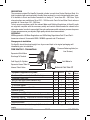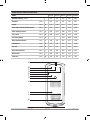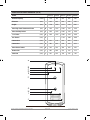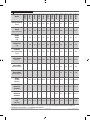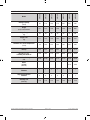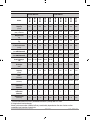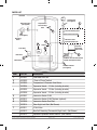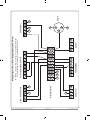
1
Back cover Front cover A5_Booklet Installation, Maintenance and User Instructions AquaFlo II Unvented Water Heaters Issued October 2012 The terms ‘Zip’ and ‘InLine’ are registered trademarks Zip Heaters (UK) Ltd. 14 Bertie Ward Way Dereham Norfolk NR19 1TE Telephone: 0845 6024533 Fax: 01362 692448 Web: www.zipindustries.co.uk Please read these instructions carefully before commencing installation. Please leave these instructions with the end user after installation. Inside Back cover Inside Front cover Contents 1 Description 2 Approvals 2 Safety Information 3 Technical data 4 / 12 Parts List 13 Installation 14 Requirements 14 Installation Site 15 Installing the appliance 15 Electrical connection / circuit diagram 20 / 21 Commissioning 22 Annual servicing 23 Warranty 24 Please read these instructions carefully before commencing installation of the AquaFlo unvented Water Heater. Please leave these instructions with the end user after installation. To ensure you have the latest revision of this instruction manual, please visit www.zipindustries.co.uk to download the latest copy. In order to preserve our environment we ask that you dispose of this product correctly. Please contact Zip Customer Service for advice on 0845 602 4533. AquaFlo Installation, Maintenance and User Instructions Page 1 of 24 V 2.01 - October / 2012 Description The corrosion resistant Zip AquaFlo Unvented cylinder is made from Duplex Stainless Steel. It is highly insulated with environmentally friendly foam enclosed in a rust resistant white steel case. It is available in Direct and Indirect versions in a family of 7 sizes from 90 – 300 litres. Triple element options are available on Direct 210 – 300 litre units. Twin Coil and Solar Direct units are available in 5 sizes from 150 - 300 litres. To help ensure compliance with the relevant Water and Building Regulations all AquaFlo units are supplied complete with the necessary safety and control devices needed to connect to the cold water mains. In order to ensure high flow-rate performance with minimum pressure drop even in lower pressure areas, pre-adjusted, high quality controls have been selected. Approvals KIWA approved to UK Water Regulations and UK Building Regulations Part G3 and Part L. Immersion element / thermostat BEAB / NEMKO approved and CE endorsed. Storage prior to installation Zip AquaFlo should be stored upright in a dry area and kept in its original packaging until immediately prior to installation. Pressure Reducing Valve (inc. Cold Inlet Set - Connections Line Strainer) Expansion Relief Valve Discharge To Tundish Cold Supply To Cylinder Cold Mains In Expansion Vessel Take Off Balanced Cold Take Off Internal Check Valve Solar Twin Solar Coil Direct û û Dual Control Thermostat (Indirect Models Only) û û Thermostat (High Limit) û û Two Port Zone Valve (Indirect Models Only) Cold Water Inlet Set 15 x 22 mm Tundish Temperature & Pressure Relief Valve Expansion Vessel Expansion Vessel Bracket 3/4” BSP Female X 22 mm Connection for Expansion Tank Immersion Heater(s) - Dependant on size and configuration û û Grommet for Solar Sensor Instruction Manual Additional items required (not supplied): Drain for the cold inlet. Isolating valve for the cold feed supply. Equipment Supplied with Cylinder AquaFlo Installation, Maintenance and User Instructions Direct Indirect Page 2 of 24 V 2.01 - October / 2012 IMPORTANT: PLEASE READ THESE INSTRUCTIONS CAREFULLY. NOTE THE SAFE OPERATIONAL REQUIREMENTS, WARNINGS AND CAUTIONS. USE THIS PRODUCT CORRECTLY AND WITH CARE FOR THE PURPOSE FOR WHICH IT IS INTENDED. FAILURE TO DO SO MAY CAUSE DAMAGE AND/OR PERSONAL INJURY, AND WILL INVALIDATE THE WARRANTY. RETAIN THESE INSTRUCTIONS FOR FUTURE USE. WARNING: Indicates a potentially hazardous situation, which, if not avoided, could result in death and/or serious injury and/or property damage. CAUTION: Indicates a potentially hazardous situation, which, if not avoided, may result in property damage. Safety Information Warning • Installation, commissioning and maintenance of this appliance must only be carried out by a competent installer holding their G3 unvented qualification, who will then be responsible for adhering to all relevant standards and regulations. • The appliance must be wired to a suitably rated double pole fused spur. • Electrical installation must comply with IEE regulations. • Isolate appliance at the main electric supply before opening the heating element cover. • The connection cable must be 2.5mm2 heat resistant (85°C HOFR) sheathed flex complying to BS 6141:1981. • This appliance must be earthed at all times. • The connecting cable must be adequately secured. • Check that the power supply is switched off prior to electrical connection. • The appliance, its wiring and piping must not be modified in any way. • The appliance must only be used when correctly installed and in perfect working order. • Maximum water supply pressure 1.0 MPa (10 bar). • Explosion hazard. Safety fittings such as the temperature & pressure relief valve must not be modified. • The appliance must not be used for any purpose other than that for which it was designed. • When the appliance has been in use for some time, the fittings may be very hot. • This appliance must not be used by any person (including children) with limited physical, sensorial or mental abilities or failing experience and/or knowledge unless they are supervised by a person responsible for their safety or received instructions about how to use the appliance. Children should be supervised in order to make sure that they do not play with the appliance. • Take care when lifting the Zip AquaFlo. Some units may exceed safe lifting limits. Do not lift without assistance. The weights of the units are given in the specifications table (see specifications on page 10 to 12) AquaFlo Installation, Maintenance and User Instructions Page 3 of 24 V 2.01 - October / 2012 CAUTION! • In case of malfunction isolate the power supply immediately. In case of leaks also isolate the water supply. Repairs must only be carried out by Zip Heaters (UK) Ltd or an authorised Zip service engineer. • If siting outside the heating envelope of the dwelling such as a garage or outbuilding then frost protection should be provided and exposed pipework should be insulated. • The appliance must be completely filled with water before being switched on. • The appliance must only be used for heating wholesome water. • Minimum water supply 0.15 MPa (1.5 bar), 20 l/min. • The Zip AquaFlo is intended for connection to mains supply only. In any other case please contact Zip on 0845 602 4533 for advice. Zip Heaters (UK) Ltd. cannot be held liable for any damages caused by failure to observe these instructions. Technical data / specification Maximum water supply pressure to pressure reducing valve....................1.0 MPa (10 bar) Note! If supply is above 1.0 MPa (10 bar) a pressure control valve must be used to bring the pressure under 1.0 MPa (10 bar) before connection to the pressure reducing valve. Operating pressure.....................................................................................0.3 MPa (3 bar) Maximum primary pressure (indirects only)................................................0.3 MPa (3 bar) Immersion Elements: Incology construction 1¾” thread, 14” long, loading 3kW @ 240V. Note! Titanium elements are also available for areas where aggressive water, constant cycling and high usage are factors. (See parts on page 13). Heat Exchanger: 22mm low profile, high efficiency stainless steel coil-in-coil. Controls: • Thermostat adjustable up to 65°C. • Over temperature safety cut-out. Manually re-settable. Operates at 85°C. • Expansion relief valve - 0.6 MPa (6 bar). • Temperature and pressure relief valve - 90°C and 0.7 MPa (7 bar). • Pressure reducing valve - 0.3 MPa (3 bar). • • • • Expansion vessel - pre-charged 0.3 MPa (3 bar). 90 - 150 Ltr units: 12 Ltr vessel. 180 - 250 Ltr units: 18 Ltr vessel. 300 Ltr units: 24 Ltr vessel. AquaFlo Installation, Maintenance and User Instructions Page 4 of 24 V 2.01 - October / 2012 Connection Points AquaFlo Direct 45° Cold Inlet Immersion 15° T&P Valve AquaFlo Indirect and Solar Compatible 66° Sec Return 40° Primary Coil 25° Stat Pocket AquaFlo Installation, Maintenance and User Instructions 38° Cold Inlet 35° 15° Primary Coil T&P Valve Immersion Page 5 of 24 V 2.01 - October / 2012 AquaFlo Direct Dimensions Model AF3090 AF3120 AF3150 AF3180 AF3210 AF3250 AF3300 (Litres) 90 120 150 180 210 250 300 Diameter (mm) 545 545 545 545 545 545 545 Height (mm) A 727 915 1102 1290 1478 1728 2041 T & P Valve (mm) B 515 703 890 1078 1266 1516 1829 Sec. Return (mm) C - - - - 1009 1259 1509 Immersion 2 (mm) D - 519 619 719 819 959 1109 Immersion 1 (mm) E 242 242 242 242 242 242 242 Cold Inlet (mm) F 192 192 192 192 192 192 192 Nominal Capacity A B C D E F AquaFlo Installation, Maintenance and User Instructions Page 6 of 24 V 2.01 - October / 2012 AQUAfLo InDIrECT DImEnSIonS Model nominal Capacity (Litres) AF4090 AF4120 AF4150 AF4180 AF4210 AF4250 AF4300 90 120 150 180 210 250 300 545 545 545 545 545 545 545 Diameter (mm) Height (mm) A 727 915 1102 1290 1478 1728 2041 T & P valve (mm) B 515 703 890 1078 1266 1516 1829 Sec. return (mm) C - - - - 1159 1409 1609 Immersion 2 (mm) D - - - - - 959 1109 Stat Pocket (mm) E 354 354 394 394 474 569 669 Immersion 1 (mm) f 339 339 379 379 414 414 414 Bottom Coil (mm) g 299 299 339 374 374 374 374 Cold Inlet (mm) H 192 192 192 192 192 192 192 AquaFlo Installation, Maintenance and User Instructions Page 7 of 24 V 2.01 - October / 2012 AquaFlo Solar Twin Coil Dimensions Model Nominal Capacity (Litres) AF5150 AF5180 AF5210 AF5250 AF5300 150 180 210 250 300 545 545 545 545 545 Diameter (mm) Height (mm) A 1102 1290 1478 1728 2041 Solar High Limit Thermostat Pocket (mm) B 890 1078 1266 1516 1829 Solar Auxillary Pocket (mm) C 890 1078 1266 1516 1829 T & P Valve (mm) D 890 1078 1266 1516 1829 Secondary Return (mm) E - - 1159 1409 1609 Boiler Dual Stat Pocket (mm) F 706 738 843 918 1043 Immersion 1 (mm) G 702 734 839 914 1039 Top Coil (mm) H 651 675 789 863 989 Solar Sensor Pocket (mm) I 354 354 429 429 429 Bottom Coil (mm) J 299 299 374 374 374 Cold Inlet (mm) K 192 192 192 192 192 A B C D E F G H I J K AquaFlo Installation, Maintenance and User Instructions Page 8 of 24 V 2.01 - October / 2012 AquaFlo Solar Direct Dimensions (Fig. B) Model AF6150 AF6180 AF6210 AF6250 AF6300 Nominal Capacity (Litres) 150 180 210 250 300 Diameter (mm) 545 545 545 545 545 Height (mm) A 1102 1290 1478 1728 2041 Solar High Limit Thermostat Pocket (mm) B 890 1078 1266 1516 1829 Solar Auxillary Pocket (mm) C 890 1078 1266 1516 1829 T & P Valve (mm) D 890 1078 1266 1516 1829 Sec. Return (mm) E - - 1159 1409 1609 Immersion 2 (mm) F 619 719 819 959 1109 Immersion 1 (mm) G 399 454 509 584 679 Solar Sensor Pocket (mm) H 354 354 429 429 429 Bottom Coil (mm) I 299 299 374 374 374 Cold Inlet (mm) J 192 192 192 192 192 A B C D E F G H I J AquaFlo Installation, Maintenance and User Instructions Page 9 of 24 V 2.01 - October / 2012 AF3150S* AF3180S* AF3210S* AF3250S* AF3300S* 300 1728 2041 1102 1290 1478 1728 2041 33 38 41 46 55 355 183 218 251 296 355 288 133 163 194 236 288 AF3250 250 AF3210 210 AF3180 180 AF3150 150 AF3120 300 Model AF3090 AF3300 AquaFlo Direct Specifications Storage Capacity (Litres) 90 120 150 180 210 250 Height (mm) x 545 Diam. 727 915 1102 1290 1478 Weight Empty (kg) 21 26 33 38 41 46 55 Weight Full (kg) 111 146 183 218 251 296 Vol within 10oC of Set Temp. (Litres) 73 102 133 163 194 236 Heat up 3kW (Minutes) 76.0 Heat up 6kW (Minutes Apxrox.) - - - - - - - 73 88 108 130 168 Heat up 9kW (Minutes Apxrox.) - - - - - - - 57 67 80 95 120 Boost re-heat (Minutes) - 58.0 72.0 82.0 96.0 Low level Immersion Elements 1 1 1 1 1 1 1 3 or 2 3 or 2 3 or 2 3 or 2 3 or 2 High level Immersion Elements 0 1 1 1 1 1 1 0 or 1 0 or 1 0 or 1 0 or 1 0 or 1 Standing Loss (kWh/day) 1.07 1.23 1.41 1.53 1.80 2.15 2.28 2.15 2.28 103.0 134.0 164.0 203.0 248.0 323.0 134.0 164.0 203.0 248.0 323.0 117.0 145.0 72.0# 82.0# 96.0# 117.0# 145.0# 1.41 1.53 1.80 * Supplied with 3 elements and 4 bosses - 3 at low level and 1 at high level. Additional elements are available for installation in the 4th boss. # If using high level element. AquaFlo Installation, Maintenance and User Instructions Page 10 of 24 V 2.01 - October / 2012 Model AF4090 AF4120 AF4150 AF4180 AF4210 AF4250 AF4300 AquaFlo Indirect Specifications Storage Capacity (Litres) 88 118 148 178 208 248 297 Height (mm) x 545 Diameter 727 915 1102 1290 1478 1728 2041 Weight Empty (kg) 23 30 38 42 45 51 60 Weight Full (kg) 111 148 186 220 253 299 357 Vol Within 10oC of Set Temperature (Litres) 74 105 132 160 188 232 285 Heat up 14.2 20.0 22.0 26.2 31.2 33.0 41.0 Re-heat (minutes) Following 70% draw off 12.0 16.0 17.2 20.4 22.0 25.0 34.0 Indirect Heat Exchanger (kW) 16.46 16.46 18.55 18.55 18.55 22.00 22.00 Boost re-heat (Minutes) - - - - - 117.0 145.0 Low level Immersion Elements 1 1 1 1 1 1 1 High level Immersion Elements 0 0 0 0 0 1 1 Standing Loss (kWh/day) 1.07 1.23 1.41 1.53 1.80 2.15 2.28 AquaFlo Installation, Maintenance and User Instructions Page 11 of 24 V 2.01 - October / 2012 AquaFlo Solar Compatible Specifications Model AF5180 AF5210 AF5250 AF5300 AF6150 AF6180 AF6210 AF6250 AF6300 Solar Direct AF5150 Solar Twin coil Storage Capacity (Litres) 147 177 207 247 297 148 178 207 248 298 Height (mm) x 545 Dia. 1102 1290 1478 1728 2041 1102 1290 1478 1728 2041 Weight Empty (kg) 40 45 48 53 63 38 42 45 51 60 Weight Full (kg) 187 222 255 300 359 186 220 253 299 358 132 160 188 232 285 132 160 188 232 285 54.1 82.7 97.9 113.9 164.3 114.0 136.8 159.6 182.4 225 37.9 57.9 68.5 79.7 115.0 79.8 95.8 111.7 127.7 159.6 18.55 18.55 22.00 22.00 22.00 - - - - - 16.46 18.55 18.55 22.00 22.00 16.46 18.55 18.55 22.00 22.00 50 60 70 90 100 50 60 70 90 100 25.0* 26.3* 31.2* 33.0* 41.0* 25.0* 26.3* 31.2* 33.0* 41.0* 12.0# 14.8# 15.5# 20.0# 25.0# 72.0 82.0 96.0 117.0 145.0 0 0 0 0 0 1 1 1 1 1 1 1 1 1 1 1 1 1 1 1 1.41 1.53 1.80 2.15 2.28 1.41 1.53 1.80 2.15 2.28 Volume within 10°C of Set Temperature (Litres) Heat up (minutes) 1 x 3kW Immersion Re-heat (minutes) 1 x 3kW Immersion Indirect Heat Exchanger (kW) Solar Heat Exchanger (kW) Dedicated Solar Capacity (Litres) Recovery solar (Minutes) Boost re-heat (Minutes) Low level Immersion Elements High level Immersion Elements Standing Loss (kWh/day) * Re-heat times based on BS12897 parameters with an 80°C primary flow at 15 l/min. # Using Indirect heat exchanger. Actual performance when installed will vary considerably dependant on the rate of solar or other renewable input, number of panels etc. AquaFlo Installation, Maintenance and User Instructions Page 12 of 24 V 2.01 - October / 2012 Parts list Hot Outlet Cold Main Non Return Valve (not supplied) Isolating Valve (not supplied) 1 Temperature & Pressure Relief Valve 3 Pressure Reducing Valve Balanced Cold Connection Pump (not supplied) Secondary Return Non Return Valve 2 6 2 Port Valve Expansion Relief Valve Tundish Dual Stat Expansion Vessel with Wall Bracket 5 From cold Inlet Set take off Boiler Flow 7 4 DO NOT fit shut off valve between Cylinder and Expansion Valve Boiler Return Drain Via Cold Inlet (not supplied) Item Part. No. Description 1 SA20001 Cold Water Inlet Set 2 SA20002 15mm x 22mm Tundish 3 SA20003 Temperature & Pressure Relief Valve SA20004 Expansion Vessel - 12 Litre (including bracket) 4 SA20005 Expansion Vessel - 18 Litre (including bracket) SA20006 Expansion Vessel - 24 Litre (including bracket) 5 SA20007 Immersion Heater 3 kW 5 SA20015 Immersion Heater 3 kW Titanium (optional) 6 SA20008 Immersion Heater Dual Stat SA20014 Solar High Limit Stat. (Not Shown) 7 SA20011 2 Port Valve SA20013 Non Self Resseting Thermostat (High Limit). (Not Shown) SA20010 Separate Expansion Vessel Bracket. (Not Shown) AquaFlo Installation, Maintenance and User Instructions Page 13 of 24 V 2.01 - October / 2012 Installation Installation prerequisites Zip Aquaflo should only be installed by a competent installer holding their G3 unvented qualification. The installation of this product is also notifiable under the national building regulations. The electrical installation including earthing and cross bonding must comply with the current IEE regulations and any Local Authority requirements. Requirements Zip AquaFlo is capable of delivering over 50 litres per minute when connected to a suitable mains supply. The high quality inlet control set with its 0.3 MPa (3 bar) operating pressure has been designed to make the most of what is available, however the performance of any unvented system is only as good as the water supply. In unvented systems both hot and cold services are supplied simultaneously from the mains so the maximum possible on-site water demand must be assessed and the water supply should be tested to ensure it can meet these requirements. If necessary consult the local water supplier regarding the likely pressure and flow rate availability. It is important that site pressure readings are taken under dynamic flow conditions, high pressures under zero flow conditions are not necessarily indicative of satisfactory performance. A minimum of 0.15 MPa (1.5 bar) at 20 l/m flow should be available. Where mains inlet pressures are likely to exceed 1.2 MPa (12 bar) then an additional upstream pressure reducing device should be fitted. A minimum of 22mm supply pipe-work should ideally be provided and existing ½” (15mm) cold mains pipe-work may need to be upgraded. Hard water treatment should be considered in areas where the calcium carbonate content is greater than 200ppm, if required adjust cylinder temperature to below 60°C. This Cylinder should only be installed by a competent installer holding their G3 unvented qualification. The installation of this product is also notifiable under the national building regulations. The electrical installation including earthing and cross bonding must comply with the current IEE regulations and any Local Authority requirements. Connecting units in parallel Multiple AquaFlo units can be connected together in parallel for applications where higher storage capacity is required. To connect in parallel, each AquaFlo should be provided with a separate cold supply while the hot outlets are connected to a common pipeline. Secondary return All AquaFlo units are suitable for use with secondary return systems. A dedicated secondary return connection is provided with a capacity of 210 litres and above. On smaller sizes the secondary return can be connected to the incoming supply. Always check that the kW loading available on direct units is sufficient to recover the heat loss in the secondary circuit in addition to any hot water drawn off. AquaFlo Installation, Maintenance and User Instructions Page 14 of 24 V 2.01 - October / 2012 Installation site Zip AquaFlo can be positioned more or less anywhere in the building but it should be remembered that for every 1 meter that an outlet is above the AquaFlo, the pressure will be reduced by 0.01 MPa (0.1 bar). If siting outside the heated envelope of the dwelling such as in a garage or outbuilding then frost protection should be provided and exposed pipe work should be insulated. Zip AquaFlo must be supported on a flat base (intended for floor standing) capable of supporting the weight of the cylinder when full. The minimum recommended cupboard size is 650mm square. It’s important that consideration is given to access for maintenance of the valves. The immersion heaters are 375mm long and access space should be provided for possible future replacement. Installing the appliance Cylinder connections All plumbing connections should be made to Zip AquaFlo and its safety devices using the 15mm or 22mm compression fittings, nuts and olives supplied. Cylinder relief valve connections Safety relief valve connections should not be used for any other purpose and no valve should be fitted between the expansion relief valve and the storage cylinder. Cold mains pipework Run the cold main through the building to the place where the AquaFlo is to be installed. Take care not to run the cold pipe near hot water or heating pipe work so that the heat pick up is minimized. Identify the cold water supply pipe and fit an isolating valve (not supplied). A 22mm BS1010 stopcock can typically be used but a 22mm quarter turn full bore valve would be better as it does not restrict the flow as much. Do not use “screwdriver slot” or similar valves. Make the connection to the cold feed of the cylinder and incorporate a drain valve (not supplied). Position the inlet control just above the Temperature & Pressure Relief Valve (TPRV) mounted on the side of the cylinder. This ensures that the cylinder does not have to be drained down in order to service the inlet control set. Ensure that the arrow points in the direction of the water flow. Select a suitable position for the expansion vessel. Mount it to the wall using the bracket provided. A 3/4” BSP female x 22mm compression connection is provided to connect the expansion vessel to the 22mm pipe. Balanced cold connection If there are to be showers, bidets or monobloc taps in the installation then a balanced cold supply AquaFlo Installation, Maintenance and User Instructions Page 15 of 24 V 2.01 - October / 2012 is a requirement. There is a 22mm balanced connection on the inlet control set that must be used for this purpose. Hot water pipework Run the first part of the hot water distribution pipework in 22mm. This can be reduced to 15 mm and 10 mm as appropriate for the type of tap etc.. Your aim should be to reduce the volume of the hot draw off pipework to a practical minimum so that the time taken for the hot water is as quick as possible. Do not use monobloc mixer tap or showers if the balanced cold connection is not provided. This arrangement will back pressurise the unit and result in discharge. Primary coil connections (Indirect Only) Compression connections are provided for the primary circuit which must be positively pumped. Primary flow and return connections are interchangeable to suit site conditions without affecting reheat times. Sealed or vented primary circuits can be used, to comply with normal installation practice the primary pressure should not exceed 0.3 MPa (3 bar) although the coil in AquaFlo is suitable for up to 0.7 MPa (7 bar) if required. The boiler may be Gas, Electric, Oil etc but must be under effective thermostatic control. Zip AquaFlo is not intended for use with uncontrolled heat sources such as some AGA’s, back boilers, solid fuel stoves etc. The two port zone valve should be installed into the primary flow pipework leading to the coil flow inlet. The direction of flow arrow should be towards the primary flow connection. On twin coil cylinders an extra thermostat boss is provided. Secondary circulation Where secondary circulation is required a circulator suitable for wholesome water should be used in conjunction with a non return valve to prevent back flow. It may be necessary to incorporate an extra expansion vessel into the circuit to accommodate the increased system water volume in larger secondary circulation systems. Where off peak electrical tariffs are being used then secondary circulation should be avoided. A secondary return boss is fitted as standard on 210, 250 & 300 litre. On smaller sizes tee into the cold feed pipe above the drain. Immersion heaters As a requirement of Building regulations the AquaFlo immersion heaters are fitted with thermal cut-out in addition to the normal control thermostat. To help ensure correct replacement the immersion heaters have a special 1¾” thread. They are of a low noise Incoloy construction and rated at 3kW at 240V. Replacement immersion heaters should be purchased from Zip Heaters otherwise the product warranty may be affected. Note! Titanium elements are also available for areas with aggressive water, constant cycling and high usage. (See parts on page 13). Under no circumstances should immersion heaters without thermal cut-outs be fitted to Zip AquaFlo. The o-ring on the head of the immersion heater should be correctly positioned and lubricated before fitting. Screw in until hand-tight then gently tighten as the o-ring will seal easily. AquaFlo Installation, Maintenance and User Instructions Page 16 of 24 V 2.01 - October / 2012 The electrical supply to each immersion heater must be fused at 13A via a double pole isolating switch to BS 3456. The cable must be 2.5mm2 heat resistant (85°C HOFR) sheathed flex complying to BS 6141:1981. Do not operate the immersion heater/s until the unit is full of water. If any sterilisation liquid is in the cylinder do not operate the immersion heater/s as this will cause premature failure. The electrical supply must be from a fused supply compliant with local regulations and fitted by a suitably qualified Electrician. Energy cutout and cylinder thermostat (Indirect Only) As a requirement of Building regulations the AquaFlo units are fitted with a thermal cut-out in addition to the normal control thermostat. This unit should be fitted to the dedicated boss on the cylinder and wired to the two port valve controlling the primary flow (see wiring diagram). AquaFlo unvented indirect Twin coil solar Indirect twin coil units can be installed in two separate formats: 1. In a solar powered system with a fossil fuel boiler. 2. In a system with two independent fossil fuel boilers. With either format it is essential the overall installation meets all current legislation including, in particular, the high limit isolation requirements of Building Regulation G3. This document is designed to assist in achieving this aim. Upper coil The upper coil is connected to the fossil fuel boiler as per the instructions for the AquaFlo single coil model with the Dual Control thermostat inserted into the middle stat pocket. The wiring requirements are as depicted in this guide. Lower coil: Solar Installation In a solar powered system the lower coil is connected to the solar heat source. Either primary coil connection may be utilised as the flow or return. The solar cylinder sensor, supplied as part of the solar controls, inserts into the lower stat pocket with the supplied grommet. It is necessary to mount the solar pump in the return pipework with the two port valve (supplied with the cylinder) installed between the cylinder and the pump. This valve is of the powered open, sprung closed design and is wired through the high limit stat which inserts into the upper stat pocket. Two wiring options for high limit isolation are provided in this guide. The control thermostat is not required in a solar installation. The remaining upper stat pocket is for the use of a sensor often supplied with a solar control package which may then provide via display on the solar control panel indication of the water temperature in the cylinder. NB: not all solar control packs provide this facility. Lower coil: Two Boiler Installation Where the lower coil is to be used with a fossil fuel boiler, the pipework requirements are as per that of a Stainless Indirect single coil cylinder described earlier in this book. However the electrical requirements mean the control thermostat inserts into the lower tank stat pocket to control the boiler input and the limit stat into the upper tank stat pocket. The two port valve may be installed into either the flow or return pipework. Wiring of the controls are as per the wiring diagram in this guide. AquaFlo Installation, Maintenance and User Instructions Page 17 of 24 V 2.01 - October / 2012 Discharge arrangement General guidance is provide by the diagram on page 19, extracted from the G3 Building Regulation Guidance. This guidance is available as a free of charge download of the G3 Approved Document from www.planningportal.gov.uk. The discharge from both the Temperature relief and expansion relief valves can be joined together via a 15mm end feed Tee. It is important that any discharge water does not collect in this pipe-work and can run freely to the tundish. The tundish should be mounted in a vertical and visible position located in the same space as the unvented hot water storage system and be fitted as close as possible and within 600mm of the safety device e.g. the temperature relief valve. The discharge pipe-work from the tundish must be routed in accordance with Part G3 of the Building Regulations. The discharge pipes and tundish should be installed in a visible location away from any electrical devices, should terminate in a safe place where there is no risk to persons in the vicinity of the discharge, be of metal and: • Be at least one pipe size larger than the nominal outlet size of the safety device unless its total equivalent hydraulic resistance exceeds that of a straight pipe 9m long i.e. discharge pipes between 9m and 18m equivalent resistance length should be at least two sizes larger than the nominal outlet size of the safety device, between 18 and 27m at least 3 sizes larger, and so on. Bends must be taken into account in calculating the flow resistance. An alternative approach for sizing discharge pipes would be to follow BS6700 Specification for design installation, testing and maintenance of services supplying water for domestic use within buildings and their curtilages. • Have a vertical section of pipe at least 300mm long, below the tundish before any elbows or bends in the pipework. • Be installed with a continuous fall. • It is preferable for the discharge to be visible at both the tundish and the final point of discharge but where this is not possible or practically difficult there should be clear visibility at one or other of these locations. Examples of acceptable discharge arrangements are: • Ideally below the fixed grating and above the water seal in a trapped gulley. • Downward discharges at a low level; i.e. up to 100mm above external surfaces such as car parks, hard standings, grassed areas etc. are acceptable providing that a wire cage or similar guard is positioned to prevent contact whilst maintaining visibility. • Discharges at a high level; e.g. in to metal hopper and metal down pipe with the end of the discharge pipe clearly visible or onto a roof capable of withstanding high temperature discharges of water and 3m from any plastic guttering systems that would collect such discharges. AquaFlo Installation, Maintenance and User Instructions Page 18 of 24 V 2.01 - October / 2012 • Where a single pipe serves a number of discharges, such as in blocks of flats, the number served should be limited to not more than six systems so that any installation can be traced reasonably easily. The single common discharge pipe should be at least one pipe size larger than the largest individual discharge pipe to be connected. If unvented hot water storage systems are installed where discharges from safety devices may not be apparent i.e. in dwellings occupied by blind, infirm or disabled people, consideration should be given to the installation of an electronically operated device to warn when discharge takes place. Note: The discharge will consist of scalding water and steam. Asphalt, roofing felt and non-metallic rainwater goods may be damaged by such discharges. Note: It is not acceptable to discharge straight into a soil pipe. See G3 3.60 for guidance. Diagram of a typical discharge pipe arrangement (extract from Building Regulations G3). Safety device e.g temperature relief valve Metal Discharge Pipe (D1) From Temperature Relief Valve to Tundish, with Continuous Fall 600 mm Maximum Pipe Length Tundish 300 mm minimum Discharge below fixed grating (G3 3.62 gives alternative points of discharge) Metal Discharge Pipe (D2) From Tundish, with Continuous Fall Discharge Below Fixed Grating Trapped Gulley AquaFlo Installation, Maintenance and User Instructions Page 19 of 24 V 2.01 - October / 2012 AquaFlo Installation, Maintenance and User Instructions Page 20 of 24 V 2.01 - October / 2012 2 2 3 ROOM STAT 1 N 3 E WIRING CENTRE 1 Br G BI O G/Y 2 PORT HEATING N L L 3 2 1 2 E 4 4 6 6 C HTG DHW ON ON 5 5 PROGRAMMER N E 3 2 E 1 C DHW OFF 7 7 E CUTOUT (COMBINED) dUOSTAT 8 8 2 BOILER SL L 9 10 9 10 1 N E G = Grey, BI = Blue, O = Orange, G/Y = Green/Yellow, Br = Brown L = Live, N = Nuetral, C = Common, SL = Switched Live, E = Earth 2 PORT (DHW) L 1 2 N E 3 2 PUMP 3 Br G BI O G/Y Wiring Diagram 2 x 2 Port Zone Valves (Typically Honeywell ‘S’ Plan) AquaFlo Installation, Maintenance and User Instructions Page 21 of 24 V 2.01 - October / 2012 3 G/Y 2 3 ROOM STAT 1 N E WIRING cENTRE 2 Br G BI O 3 PORT MID POSITION 2 N 1 L L 2 1 C 5 4 HTG ON 5 1 4 N E E 3 3 2 6 6 C DHW ON PROGRAMMER E DHW OFF 7 7 E CUTOUT (COMBINED) dUOSTAT 8 8 2 N BOILER SL L 9 10 9 10 1 E W = White, G = Grey, BI = Blue, O = Orange, G/Y = Green/Yellow, Br = Brown L = Live, N = Nuetral, C = Common, SL = Switched Live, E = Earth Wiring Diagram 3 Port + 2 Port (Typically Honeywell ‘Y’ Plan) L 1 2 N E 3 2 3 PUMP Br G BI O G/Y 2 PORT (DHW) Commissioning Filling Check all connections for water tightness including any factory made connections such as the immersion heater and the temperature and pressure relief valve. The pressure in the expansion vessel should be checked to ensure it is 0.3 MPa (3 bar) (45 psi). The valve is of the car tyre (Schrader) type. The hot tap furthest away from the AquaFlo should be opened before filling the system to let air out. The system should be flushed before use. The remaining taps should be opened in turn to expel air. Direct units The system must be fully filled and flushed before switching on the power to the immersion heaters and allowing the unit to heat up. The immersion heater is supplied preset at 55°C. Turning fully to + sets to approx 65°C. Indirect units Ensure the lever on the two port valve is set to the filling position and use the boiler manufacturers commissioning instructions to fill the primary circuit. When full release the lever. Switch the programmer to Domestic Hot water (DHW) and allow the unit to start to heat. Adjust the dial of the dual thermostat to between 55°C and 65°C as required. Storage temperature A storage temperature of 60-65°C is normal for both direct and indirect AquaFlo. In hard water areas consideration should be given to reducing this to 55-60°C. In many healthcare applications the guidance on Legionella control and safe water delivery temperatures will require storing the water at 60-65°C, distributing at 50-55°C and using thermostatic mixing valves to control the final temperature. For details consult the NHS estates guidance on safe hot water temperatures. Safety valve checks Any water coming from either the expansion relief valve or the temperature / pressure relief valve during heat up is indicative of a problem which needs to be identified and rectified. The temperature relief and expansion relief valves should be fully opened, one at a time then both together allowing as much water as possible to flow through the tundish. Check that your discharge pipework is free from debris and is carrying the water away without spillage over the tundish and release the valves and check that they re-seat properly. General Servicing should only be carried out by competent installers and any spare parts used must be purchased from Zip Heaters. NEVER bypass any safety devices or operate the unit without them fully operational. Draining Isolate from the electrical supply to prevent the immersion heaters burning out. Isolate the unit from the cold mains. Attach a hose to the draining tap ensuring it reaches to a level below the unit. (This will ensure an efficient syphon is set up and the maximum amount of water is drained from the unit). Open the hot tap closest to the unit and open the draining tap. WARNING: WATER BEING DRAINED OFF MAY BE VERY HOT! AquaFlo Installation, Maintenance and User Instructions Page 22 of 24 V 2.01 - October / 2012 Annual servicing A competent installer should carry out the following checks on an annual basis, ideally at the same time as the annual boiler service. 1. The expansion relief valve on the inlet control set should be eased open allowing water to flow for 5 seconds. The valve should then be closed making sure it re-seats correctly. Repeat this procedure with the pressure/temperature relief valve. Always ensure that the discharge pipework is allowing the water to drain away adequately. If not check for blockages etc. and clear. WARNING: THE WATER DISCHARGED MAY BE VERY HOT! 2. Ensure that any immersion heaters that are fitted are working correctly and that they are controlling the water at a temperature of between 55°C and 65°C. 3. Make sure the pressure in the expansion vessel is charged to 0.3 MPa (3 bar). If not turn off the water supply to the unit and open a hot tap, run the tap until the water ceases to flow. The valve on the expansion vessel is a Schrader (standard car tyre) type. Air or CO2 can be used to re-pressurise the expansion vessel. 4. Remove the head on the inlet control set by unscrewing, and clean the mesh filter within. Your Warranty May Be Void Without Proof Of Annual Servicing. AquaFlo Installation, Maintenance and User Instructions Page 23 of 24 V 2.01 - October / 2012 Warranty The AquaFlo stainless steel vessel carries a transferable 25 year warranty against faulty materials or manufacture provided that: • It has been correctly installed by a competent installer as per this document and all the relevant standards, regulations and codes of practice in force at the time. • It has not been modified in any way, other than by Zip Heaters (UK) Ltd. • No components supplied with the AquaFlo have been removed for unauthorised repair or replacement. • It has not been misused, tampered with or subjected to neglect. • It has only been used for the storage of wholesome water. • It has not been subjected to frost damage. • The unit has been serviced annually. • The system is fed from a public water supply. • The warranty period commences from the date of purchase subject to registration of the product within 60 days of installation. Please note that invoices for servicing may be requested to prove that the unit has been serviced annually. All the components fitted to/or supplied with the AquaFlo carry a 2 year warranty. EXCLUSIONS –The warranty does not cover: The effects of scale build up. Any labour charges associated with replacing the unit or its parts. Any consequential losses caused by the failure or malfunction of the unit. In the event of a problem contact Zip Heaters on 0845 602 4533 for advice. Your Zip Aquaflo requires annual servicing. You should employ a competent installer to perform the annual servicing. Zip Heaters service department can be contacted on 0845 602 4533 to arrange servicing or repair. If water is flowing from the safety valves through the Tundish, this indicates a fault condition and action is needed. If this water is hot turn the boiler and/or the immersion heater off. Do not turn off the water until the discharge runs cool. The discharge may also stop. Contact Zip Heaters on 0845 602 4533 or call a competent plumber out to service the unit. Tell them you have a fault on an unvented cylinder. Zip Heaters stock all the spare parts that may be required. AquaFlo Installation, Maintenance and User Instructions Page 24 of 24 V 2.01 - October / 2012