1
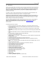
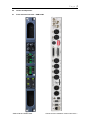
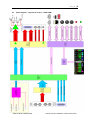
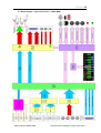
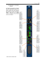
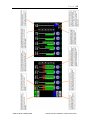
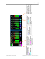
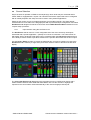
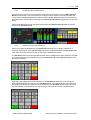
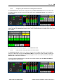
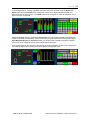
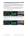
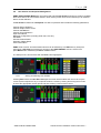
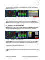
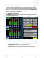
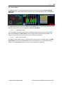
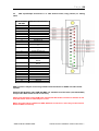
Page |2 SAFETY Unless otherwise stated TSL equipment may be installed at any angle or position within an operating temperature range of 5 - 30C. All TSL equipment conforms to the EC Low Voltage Directive: EC Low Voltage Directive (73/23/EEC)(OJ L76 26.3.73)(LVD). Amendment: (93/68/EEC) (OJ L220 30.8.93). In all cases the frame of the equipment must be earthed on installation. Where appropriate, the earth pin on the IEC mains inlet connector is connected to the metal frame of the equipment, to 0 volts on the internal DC PSU and to signal ground unless otherwise stated. All metal panels are bonded together. Check that the voltage selector setting (if fitted) and the fuse rating is correct for the local mains supply. Due consideration for cooling requirements must be given when mounting the equipment. It is recommended that a 1RU of rack space, or a vent panel, should be left above and below the unit. SAM1-3GM and SAM1 MADI Combined User Handbook Version One Issue 1 Page |3 WARRANTY, MAINTENANCE AND REPAIR All TSL products have a one year warranty period starting from the date it leaves the factory. A repair warranty is to apply. That is, the product is to be returned for repair with no replacement and an exchange shipping policy is also to apply. TSL offers a seven day DOA policy together with an exchange shipping policy. That is, if a product has been declared ‘dead on arrival’ within a seven day period a warranty replacement will be shipped. A temporary replacement may be available where, for operational reasons, it is imperative that service is continued. The customer will be asked to enter into a ‘loan agreement’ for the duration of repair. All faulty equipment returned to TSL for repair will, where possible, be returned to the customer within seven working days. TSL Returns Procedure Please telephone +44 (0)1628 676221 (Fax: +44 (0)1682 676299) and ask for Customer Support, detailing the model and serial number of the equipment, who will provide a Returns Number. This will enable us to track the unit effectively and will provide some information prior to the unit arriving. For each item, this unique Returns Number must be included with the Fault Report sent with the unit. A contact name and telephone number are also required with the Fault Report sent with the unit. Fault report details required. Company: Name: Address: Contact Name: Telephone number: Fax number: Email address: Returns Number: Symptoms of the fault (to include switch setting positions, input signals etc): Packing Please ensure that the unit is well packed as all mechanical damage is chargeable. TSL recommends that you insure your equipment for transit damage. The original packaging, when available, should always be used when returning equipment. If returned equipment is received in a damaged condition, the damage should be reported both to TSL and the carrier immediately. SAM1-3GM and SAM1 MADI Combined User Handbook Version One Issue 1 Page |4 1.0 Introduction 2.0 Control and Operation 2.1 Front and Rear Overview – SAM1 3GM 2.2 Front and Rear Overview – SAM1 MADI 2.3 Block Diagram – Signal and Control, SAM1 3GM 2.4 Block Diagram – Signal and Control, SAM1 MADI 2.5 Quick Start – Front Panel Controls 2.6 Source Selection 2.7 2.6.1 Input selection using the Hot Source List 2.6.2 Configuring the Hot Source List 2.6.3 Deleting from the Hot Source List 2.6.4 Configuring the Hot Source List using Mixer Pair Select 2.6.5 Input selection using the Mixer Pair Select Menu Configuring and Naming Input Channels 2.7.1 2.8 Menu / Setup/ Source Label Editor User Presets and Snapshot Management 2.8.1 Saving and naming User Presets 2.8.2 Loading User Presets 2.9 Setup Menu 1 - SAM1 3GM and SAM1 MADI 2.9.1 Meter Menu – Selecting Scale Type 2.9.2 dBFs Menu 2.9.3 Meter Peak Menu 2.9.4 Meter Zero and Block Menu 2.9.5 Meter Hold Menu 2.10 Setup Menu 1 - SAM1 MADI only 2.10.1 SAM1 MADI Unique Setup Menu 2.10.2 MADI Source Select 2.10.3 MADI Reference Select 2.10.4 MADI Wordclock Termination 2.10.5 MADI Bypass 2.11 MADI Status Menu - SAM1 MADI only 2.12 MADI Test Signal Generator - SAM1 MADI only 2.13 Source Menu 2.13.1 Label Rotate Timer 2.13.2 Main Sources Enable 2.14 Setup Menu 2 2.14.1 User Save Menu 2.14.2 GPI Menu 2.14.3 Internal / External Loudspeaker Mute 2.15 Software Menu SAM1-3GM and SAM1 MADI Combined User Handbook Version One Issue 1 Page |5 3.0 Pin-out Details 3.1 Analogue XLR Connectors 3.2 Analogue Output connector – D25 Socket Pinout 3.3 AES Input/Output connector – D25 Socket Pinout 3.4 GPI connector 3.5 Remote Control connector 3.6 DIP switch configuration functions 4.0 Notes 5.0 General Notes 6.0 Specifications 7.0 HDC-2T Audio Monitor Module Specification SAM1-3GM and SAM1 MADI Combined User Handbook Version One Issue 1 Page |6 1.0 Introduction SAM1 3GM and SAM1 MADI are deceptively simple yet highly sophisticated compact multichannel audio monitor units designed for use anywhere within a Broadcast environment that employs SDI, MADI, AES or analogue audio infrastructure. The flexible monitoring configuration system delivers a unique combination of bespoke audio monitoring and mix capabilities designed to simplify operations and workflow. The SAM1 is a 1RU x 250mm Audio Monitoring Unit controlled via a simple hard/software user interface with dual fully assignable high resolution, LCD bargraph displays. As with any new product which relies on software, it is possible that you may find minor bugs or perhaps think of enhancements which would improve the operation of SAM1. In the event of either scenario, please feel free to contact TSL Products via your local reseller or directly on +44 1628676221, asking for the SAM series Product Manager. TSL will be releasing upgrades and feature enhancements from time to time – as a purchaser of SAM1 3GM and/or SAM1 MADI you can receive these directly, free of charge, through your reseller or as a download from TSL Products. Please refer to www.tslproducts.com for announcements. The following features are standard: Single or Dual (SD Only) Auto-sensing, 1080p (60, 59, 94 and 50Hz), HD/SDI video input De-embedded audio monitoring from video (HD/SDI) with intuitive selection from up to sixteen channels (SDI 1 only) Coaxial and Optical MADI monitoring of up to 64 channels at a sample rates of 48kHz (SAM1 MADI only) Coaxial and Optical MADI clocked outputs as well as passive Coaxial relay bypass (SAM1 MADI only) Single Mode Fibre MADI connection as standard, Multi Mode available on request (SAM1 MADI only) 64 Channel MADI Test Signal Generator (SAM1 MADI only) Wordclock reference (SAM1 MADI only) 4 AES (4 Pairs/8 Channel) Inputs – 110Ohm Balanced or 75 Ohm unbalanced via optional CABD25-BNC cable 2 Analogue Stereo Inputs 10 stereo/ 20 dual mono assignable input channel monitor/mixer One-touch downmix of discrete multichannel audio to stereo for compatibility monitoring Re-clocked HD/SDI video output. Choice of user selectable bargraph scales (BBC PPM, EBU PPM, EBU Digital, Nordic, VU and DIN) 18 User programmable presets. Manage, recall and save favourite configurations via USB stick or SD card User configurable ‘Hot Source List’ input select Virtual ‘Scribble Strip’ channel alias naming Unique input audio ‘Preview’ function Fixed and variable analogue stereo outputs Fixed and variable AES stereo outputs Variable stereo analogue outputs (Monitor Buss) High quality internal full range loudspeaker system GPI control of cut/dim and preset recall Dual 12V DC inputs Serial remote control Network ready Headphone output with LS muting Compact, lightweight (3.1Kg) 1RU case, 250mm deep SAM1-3GM and SAM1 MADI Combined User Handbook Version One Issue 1 Page |7 2.0 Control and Operation 2.1 Front and Rear Overview – SAM1 3GM SAM1-3GM and SAM1 MADI Combined User Handbook Version One Issue 1 Page |8 2.2 Front and Rear Overview – SAM1 MADI SAM1-3GM and SAM1 MADI Combined User Handbook Version One Issue 1 Page |9 2.3 Block Diagram – Signal and Control – SAM1 3GM SAM1-3GM and SAM1 MADI Combined User Handbook Version One Issue 1 P a g e | 10 2.4 Block Diagram – Signal and Control – SAM1 MADI SAM1-3GM and SAM1 MADI Combined User Handbook Version One Issue 1 P a g e | 11 2.5 Quick Start – Front Panel Controls The following three diagrams describe the basic functionality of the SAM1 3GM and SAM1 MADI hardware and screen controls, they also describe the onscreen icons and ‘at a glance’ features which make both SAM1 models amongst the simplest compact multichannel audio monitor to use on the market SAM1-3GM and SAM1 MADI Combined User Handbook Version One Issue 1 P a g e | 12 SAM1-3GM and SAM1 MADI Combined User Handbook Version One Issue 1 P a g e | 13 SAM1-3GM and SAM1 MADI Combined User Handbook Version One Issue 1 P a g e | 14 2.6 Source Selection Key to the ease of operation of SAM1 is the simplicity by which audio may be monitored and/or mixed. SAM1 is equipped with a 10 pair / 20 channel mixer/monitor system that can be configured with an entirely bespoke user setup and can be used in many diverse applications. Setting up the monitor for use is simple and intuitive yet incredibly powerful. The SAM1 boasts several means to route audio to the bargraph pairs with a quick and simple configuration tool called Hot Source List designed for hands-on fast track use and Main Sources Menu intended for more complex setup processes. 2.6.1 Input selection using the Hot Source List The Hot Source selector menu is a user configurable list of the most commonly used inputs associated with a specific application – perhaps a TV Show or Production. The entire total of 54 SDI, MADI, AES or analogue signal pairs may be contained within the Hot Source List however it is the ability to restrict the list to just those relevant to the operator that makes this function unique. Use the Scroll / Select encoder to choose the bargraph pair you wish to configure; Access to the Hot Source List is made by a single short press of the ‘Source’ button to the left of the left hand display. The default Hot Source List displayed on the right hand screen is configured as shown with a subtle variation between SAM1 3GM and SAM1 MADI. Now use the encoder to highlight the required source and it will be routed automatically to the chosen bargraph channel pair. SAM1-3GM and SAM1 MADI Combined User Handbook Version One Issue 1 P a g e | 15 2.6.2 Configuring the Hot Source List The Hot Source List can be configured from the Hot Source List itself or from the Main Sources Menu (described later). If the user wishes to change or add an input to a Hot Source button this can be done by simply highlighting the button using the Scroll / Select encoder and then pushing and holding the encoder until the following menu Select New Hot Source appears as can be seen below. Select the desired source type and pair and then select the Send to Hot List button to add the choice to the Hot Source List 2.6.3 Deleting from the Hot Source List Sources can easily be deleted from the Hot Source List if they are no longer required for a particular configuration. If the ‘Del Src from List’ button is highlighted within the Hot Source List menu then any inputs selected via the encoder will be deleted from the list. The Del Source button has two operational states. When highlighted as shown below the selection of a single unwanted input will delete it from the Hot Source List and the Del Source button will then become inactive By pushing and holding the encoder selection on the Del Source button the mode changes to allow multiple deletions of inputs from the Hot Source List. The example below shows that all of the default input buttons for SDI2 have been deleted from the Hot Source List using and the list has automatically concatenated by moving the active sources to the left of the deleted buttons. SAM1-3GM and SAM1 MADI Combined User Handbook Version One Issue 1 P a g e | 16 2.6.4 Configuring the Hot Source List Using Mixer Pair Select The Hot Source List can also be configured using the Mixer Pair Select menu. Press and hold the Source button to the left of the left hand display and the Mixer Pair Select menu appears as shown below. Individual or multiple sources can be selected by highlighting any or all of the input types the user wishes to add to the Hot Source List as shown in the example below where SDI1 pairs 5 to 8 have been added. The selection will automatically appear on the Hot Source List 2.6.5 Input selection using the Mixer Pair Select Menu The Mixer Pair Select menu can be used to route single or multiple selections to the bargraph pairs as an alternative to using the Hot Source Menu. It can also be used to audibly preview any available source without adding it to the input bargraph screen and to add selections to the Hot Source List as described elsewhere. Press and hold the Source button to the left of the left hand display and the Mixer Pair Select menu appears as shown below. SAM1-3GM and SAM1 MADI Combined User Handbook Version One Issue 1 P a g e | 17 In the example below, a group of 8 MADI input pairs has been selected using the Mixer Pair Select menu and the Take All button pressed to route them to eight adjacent bargraphs as depicted on the left hand screen. The TAKE button auto configures to ‘Take All’ whenever more than one source is selected. When the Preview button is switched to Preview On any channel selected will automatically be routed to the SAM1 loudspeakers system and so that it can be heard before being routed to the Input Bargraph Display or Hot Source List. This unique feature enables operators to double check they are choosing the correct audio signal before selecting it. In the example below, the operator is previewing the audio embedded on SDI1 Pair1 and the left hand display depicts the incoming audio level against the bargraph scale. SAM1-3GM and SAM1 MADI Combined User Handbook Version One Issue 1 P a g e | 18 2.7 Configuring and Naming Input Channels – User Alias Labels Any audio input channel can be given a user alias label which will be shown in the ‘virtual scribble strip’ area above the input bargraph pair. A 10 character label is permitted enabling the user to create a label which provides clear and easy recognition of any or all bargraph pairs however the system will automatically truncate any entries that include multiple block capitals that will not fit within the text field provided. The Source Label Editor can be accessed by pushing and holding the encoder over any of the input channel selectors represented within the Hot Source List or Mixer Pair Select menu. It can also be accessed via the setup menu using hard and soft button selection as follows; 2.7.1 Menu/Setup/Source Label Editor The Source Label Editor is shown below To assign a Source Label simply use ‘Clear’ to wipe the text boxes of the default label, select the box you wish to label and rotate the encoder to scroll through the available alphabet, numbers and punctuation marks – remember to press ‘Save’ to assign the new label or use ‘Default’ to retrieve the system label The example below shows a configured label and a bargraph display that has been programmed to show a typical SAM1 3GM setup SAM1-3GM and SAM1 MADI Combined User Handbook Version One Issue 1 P a g e | 19 2.8 User Presets and Snapshot Management SAM1 3GM and SAM1 MADI both use internal and external User Preset memories to enhance usability; there are a total of 18 User Presets stored in local memory which can then be backed up to an external device via the USB slot. A User Preset is defined as a Snapshot of a state of operation and includes the following parameters; Channel Source Selection Channel Output ‘Send’ Levels Channel Pan/Balance Channel Format Selection Input User Names Bargraph Configuration (including Scale, Ref, Zero etc.) GPI Mode Internal LS Mute Status External LS Mute Status User Preset Name SAM1 holds a total of 18 Internal Memories that can be backed up to a USB memory stick (front panel port) or SD Card (rear panel slot). Access to the USER PRESET menus is via the front panel Menu button followed by the Save / Load functions The Setup menu is shown below with the Save button highlighted 2.8.1 Saving and Naming User Presets Pressing Save enters the User Save Management screen which enables the user to back up the current system snapshot to any of 18 preset locations, chosen by clicking and turning the encoder to select the appropriate number preset and then entering a name of their choice. SAM1-3GM and SAM1 MADI Combined User Handbook Version One Issue 1 P a g e | 20 2.8.2 Loading User Presets Pressing Load enters the User Presets directory where the user can select to recall any other 18 user presets to be the active snapshot. In the example below the User Preset ‘Soccer Saturday’ is recalled from location ‘01’. The entire collection of 18 user preset can be backed up to or recalled from an external storage device such as a USB stick (thumb drive) or SD card providing that card has been prepared with a top level folder named ‘SAM1-3GM’ or ‘SAM1-MDI’. When a storage device is inserted into the SAM1, it will be recognised and the USB Load and USB Save buttons will appear on Setup menu as shown previously. Select either button to store or recall the system snapshot cache. SAM1 asks the operator to confirm if a USB Save command is required to overwrite an existing stored memory cache. 2.9 Setup Menu 1 – SAM1 3GM and SAM1 MADI Setup Menu includes options for different Scales, Reference Levels, Peak Hold, Input Naming and access to the Setup 2 Menu. By clicking to select the appropriate button, individual sub menus are selected and options chosen via rotation of the encoder. 2.9.1 Meter Menu – Selecting Scale Type Pressing the Meter button and turning the encoder accesses the bargraph scale options. SAM1 is able to accurately replicate EBU Digital, EBU PPM, BBC PPM, DIN PPM, Nordic PPM and VU scales and ballistics. Please note that the selection of a scale type within the Meter screen will only be remembered by SAM1 as a preset once the selection has been saved to internal memory using the User Preset commands described previously. This restriction enables the user to save preset conditions which work using different bargraph scales. 2.9.2 dBFs Menu The dBFs parameter selection can be used to alter the 0dBu reference level from between -12 and -24 dBFs. SAM1-3GM and SAM1 MADI Combined User Handbook Version One Issue 1 P a g e | 21 2.9.3 Meter Peak Menu The Peak parameter selects the offset level between the Reference dBFS setting and the onset of Peak indication (the point where the bargraph changes colour to red) from between +1dB and +18dB. 2.9.4 Meter Zero and Block Menu The Meter Peak selects between two modes of peak indication displayed on the channel bargraphs. The Bar Mode illuminates the bargraph as red once the audio level exceeds the peak value. In Block Mode the bargraph illuminates in yellow when the audio level exceeds the reference value and then red when it exceeds peak 2.9.5 Meter Hold Menu SAM1 features a simple Peak Hold indicator which may be turned on and off using the Meter Hold Menu. 2.10 Setup Menu 1 – SAM1 MADI Only 2.10.1 SAM1 MADI unique setup menu SAM1 MADI features a number of unique menus relating specifically to MADI operation that are do not appear within the setup menus of the SAM1 3GM. When the Menu button on SAM1 MADI is pressed the following screen appears on the right hand LCD display. 2.10.2 MADI Source Select The MADI Src button is used to select which MADI source is active and effectively toggles between the Coaxial (BNC) or Optical input port. The active input signal will be ‘reclocked’ out of both Coaxial and Optical output connections regardless of the chosen input format. 2.10.3 MADI Reference Select The MADI Ref button is used to select whether the MADI input is referenced to the internal clock or ‘Coax Reference’ provided by the Wordclock connection. SAM1 MADI is resilient to clocking issues however it is strongly advised that all digital input connections to SAM1 3GM and SAM1 MADI are referenced to the same timing system. 2.10.4 MADI Wordclock Termination The MADI WC button is used to turn the 75 ohm termination of the Wordclock reference connector on and off SAM1-3GM and SAM1 MADI Combined User Handbook Version One Issue 1 P a g e | 22 2.10.5 MADI Bypass SAM1 MADI features a relay which is wired across the Coax Input and the Coax Loop output connectors. In default, this relay is switched out of circuit and the Coax Input fed to the MADI receiver circuitry whist the reclocked output is fed to both Coax outputs simultaneously. If SAM1 MADI is wired in series with other devices using the loop connection then the MADI Bypass relay can be activated via the setup menu to divert MADI away from the SAM1. The relay will also switch to bypass mode in the event that SAM1 power should fail thus maintaining MADI connectivity to any serially connected downstream MADI devices. 2.11 MADI Status – SAM1 MADI Only The MADI Status button is used to access a secondary menu that provides visual feedback of connected MADI and reference signals. Coax Present – Shows presence and channel counts of a connected coax source Optical Present – Shows presence and channel counts of a connected optical source Ext Word Clock Ref – Displays the presence of a connected Wordclock reference source Coax Madi Bypass – Highlights if the coax bypass relay is active Selected WC Locked – Describes whether the selected reference is locked or not SAM1-3GM and SAM1 MADI Combined User Handbook Version One Issue 1 P a g e | 23 2.12 MADI Test Signal Generator – SAM1 MADI Only The SAM1 MADI features a 64 channel test signal generator that outputs test tones onto the coax and optical MADI output connections when activated. This useful feature can be used to help setup MADI systems or to check downstream MADI equipment. As described on the Test Signal Generator page, the test tones increment in 100Hz intervals from 800Hz at channel 1 up to 7.1kHz at channel 64. MADI Ch. 1 2 3 4 5 6 7 8 9 10 11 12 13 14 15 16 Freq. (Hz) 800 900 1000 1100 1200 1300 1400 1500 1600 1700 1800 1900 2000 2100 2200 2300 MADI Ch. 17 18 19 20 21 22 23 24 25 26 27 28 29 30 31 32 SAM1-3GM and SAM1 MADI Freq. (Hz) 2400 2500 2600 2700 2800 2900 3000 3100 3200 3300 3400 3500 3600 3700 3800 3900 MADI Ch. 33 34 35 36 37 38 39 40 41 42 43 44 45 46 47 48 Freq. (Hz) 4000 4100 4200 4300 4400 4500 4600 4700 4800 4900 5000 5100 5200 5300 5400 5500 MADI Ch. 49 50 51 52 53 54 55 56 57 58 59 60 61 62 63 64 Freq. (Hz) 5600 5700 5800 5900 6000 6100 6200 6300 6400 6500 6600 6700 6800 6900 7000 7100 Combined User Handbook Version One Issue 1 P a g e | 24 2.13 Source Menu The Source button is a shortcut means for operators to access the collected SAM1 3GM and SAM1 MADI input routing and associated function menus. Selecting Source opens the Sources Sub Menu The Main Sources, Hot Source and Source Label Editor menus are described elsewhere in this document, the remaining two are unique to the Sources Sub Menu 2.13.1 Label Rotate Timer The Label Rotate Timer button sets the time coefficient at which rate the source names shown within the Hot Source and Main Source menus toggle between their default and aliases. The range can be set between 0.25 secs and 5 secs in quarter second steps 2.13.2 Main Sources Enable The Main Sources Enable button is a selection which can be made to restrict access to the Main Source Menu from the front panel Source button so that operators can only change the input selection via the Hot Source option set up by a Tech Supervisor or Manager. SAM1-3GM and SAM1 MADI Combined User Handbook Version One Issue 1 P a g e | 25 2.14 Setup Menu 2 Accessed via Setup, Setup Menu 2 includes additional functions used to tailor SAM1 3GM to meet customer’s specific operational needs. Setup 2 Menu includes options to protect User Presets, GPI Action, External and Internal Loudspeaker Mute, and to access the Software Management Menu. Setup Menu 2 looks like this 2.14.1 User Save Menu The User Save Menu enables an Engineer or Technician to Lock or Unlock the User Preset management system onboard SAM1. In Locked mode a user is able to recall the Home Preset but unable to save or recall memories from internal or external (USB or SD Card) locations. 2.14.2 GPI Menu The GPI Menu enables an Engineer or Technician to select whether GPI inputs respond to Latching or Momentary closures from external devices. The GPI connector can be used to Cut/Dim the internal and external Loudspeakers, and to recall User presets 1 to 5. The pin-out is described in Section 3. In Momentary Mode, Dim and Cut GPI's latch in a toggle manner, i.e. one closure to ground toggles the function ON; the next ground toggles it OFF. In an ON state; the GPI pin is driven low to allow an LED to be fed from the port. This LED drive is briefly pulsed high at about 100Hz to allow the port to be read whilst it is driving. The preset recall GPI’s in ‘Latching’ mode are mutually exclusive. 2.14.3 Internal / External Loudspeaker Mute The SAM1 is designed to be used with either Internal or External Loudspeaker Systems. Users may wish to define User Preset conditions which associate the operation of the unit with internal speakers for in one state and external speakers in another. To facilitate this kind of hybrid operation the SAM1 is equipped with individual Loudspeaker Mute buttons which can be configured with different functionality dependant upon their desired use and then saved to individual presets. In the event that SAM1 is installed for use with external speakers only with the intention to mute the internal speakers, a DIP switch on the rear panel can be used to override the Internal LS Mute button in Setup 2 Menu. SAM1-3GM and SAM1 MADI Combined User Handbook Version One Issue 1 P a g e | 26 2.15 Software Menu TSL is committed to providing customers with free life of product software updates as the features of SAM1 evolve and any bugs are addressed. New code is made available via our reseller distribution channels and as a download from the TSL website. www.tslproducts.com System Software may be updated by the owner via either the front panel USB Port (using a USB memory stick) or the rear panel SD Slot. Accessing the path Setup/ Setup2/ SWare the SAM1 3GM/MADI will enter a menu page which reports the current software versions of the onboard Front Panel driver board (FP6), FPGA and PIC devices on the upper three information fields. If a memory device is inserted containing a software revision the three update fields will be displayed as illustrated below; In order to commence the upload sequence, simply press the UPDATE button and the FP6, FPGA, MADI card and PIC code will be loaded in order. Progress in indicated via the 0-100% scale. Once complete, SAM1 will display a message confirming that the process has been successfully concluded. Although an updated SAM1 will function without performing a factory reset the user may wish to do so in order to remove any residual data such as stored memories or settings. To perform a factory reset it is necessary to remove power from the unit and then re-apply power whilst pressing the Menu button until a message appears to confirm that Factory Default has been reloaded. Press Menu once more and you will be able to operate SAM1 with the new firmware active. The action of restoring Factory Default status will remove any stored memories from the SAM1. Please backup and restore memories from an external device if required. Please note that the UPGRADE sequence may take several minutes and may appear to ‘stall’ – it is important not to interrupt the process or to remove power from the device during a software upload as this may render the AMU unusable. SAM1-3GM and SAM1 MADI Combined User Handbook Version One Issue 1 P a g e | 27 3.0 Connectivity and pin-out details SAM1-3GM/MADI uses industry standard connectivity wherever possible. The D25 connectivity used for analogue and AES I/O adopts a pinning convention commonly used for Yamaha Commercial Audio equipment and breakout cables are readily available at low cost from companies such as www.cpc.farnell.com www.hosatech.com and many others. For unbalanced AES I/O connectivity an optional BNC breakout cable, CAB-D25-BNC, is available from TSL or your local reseller. When used in conjunction with SAM1, DIP switch 2 (AES Impedance) must be switched to the 75 ohm position. 3.1 Analogue XLR Connectors – Stereo Variable Output (Monitor Buss) PIN 1 2 3 1 2 3 CONN ANALOG 1 ANALOG 1 ANALOG 1 ANALOG 2 ANALOG 2 ANALOG 2 FUNCTION GND 1 IN+ 1 INGND 2 IN+ 2 IN- 3.2 Analogue Output Connector – D25 Socket Pinout on unit, Plug (shown) on mating cable. D 25 SOCKET ON AMU AUDIO OUT PIN NO 1 14 2 15 3 16 4 17 5 18 6 19 7 20 8 21 9 22 10 23 11 24 12 25 13 FUNCTION A8+ (Var. Mon R) A8- (Var. Mon R) Ground A7+ (Var. Mon L) A7- (Var. Mon L) Ground A6+ (Fixed Mon R) A6- (Fixed Mon R) Ground A5+ (Fixed Mon L) A5- (Fixed Mon L) Ground A4+ Unused A4- Unused Ground A3+ Unused A3- Unused Ground A2+ (Fixed Mix 1R) A2- (Fixed Mix 1R) Ground A1+ (Fixed Mix 1L) A1- (Fixed Mix 1L) Ground N/C SAM1-3GM and SAM1 MADI Combined User Handbook Version One Issue 1 P a g e | 28 3.3 AES Input/Output Connectors 1-4– D25 Socket Pinout, Plug (shown) on mating cable. D 25 SOCKET ON AMU AES INPUTS/OUTPUTS PIN NO 1 14 2 15 3 16 4 17 5 FUNCTION Ch1&2 In 1+ Ch1&2 In 1Ch3&4 In 2+ Ch3&4 In 2Ch5&6 In 3+ Ch5&6 In 3Ch7&8 In 4+ Ch7&8 In 4Ch1&2 Fixed Mix 1 Out 1+ Ch1&2 Fixed Mix 1 Out 1Ch3&4 Unused 2+ Ch3&4 Unused 2Ch5&6 Fixed Mon Out 3+ Ch5&6 Fixed Mon Out 3Ch7&8 Var. Mon. Out 4+ Ch7&8 Var. Mon. Out 4N/C Ground Ground Ground N/C Ground Ground Ground Ground 18 6 19 7 20 8 21 9 22 10 23 11 24 12 25 13 AES connectors may be wired using unbalanced terminations for SPDIF and 75R coaxial systems. Optional AES breakout cable CAB-D25-BNC-2 is available from TSL Sales (+44 1628 676200) and provides BNC Socket to D25 connectivity. Please note that when using SAM1 with unbalanced AES audio connections that the 75/110 ohm DIP Switch must be selected prior to use. When using the D25 for unbalanced AES, AES XLR connectors 1 and 2 may not be used for balanced AES connectivity. SAM1-3GM and SAM1 MADI Combined User Handbook Version One Issue 1 P a g e | 29 3.4 GPI Connector – D9 Socket. Not defined: Contact TSL Products Support for details 3.5 Remote Control Connector/ RS 422 - D9 Socket This is wired for RS422 slave operation. D9 1 6 2 7 3 8 4 9 5 3.6 CONTROL 0V 0V TXTX+ RX+ RX0V 0V N/C DIP switch configuration functions – To be confirmed SWITCH 1 2 3 4 5 6 7 8 FUNCTION tbc AES Impedance (75R Up/110R Dn) Internal LS Mute (Mute Up/On Dn) tbc tbc Analogue (XLR) Output (Fixed/Variable) tbc tbc SAM1-3GM and SAM1 MADI Combined User Handbook Version One Issue 1 P a g e | 30 4.0 Notes There are no user adjustable assemblies/components within this unit. This unit requires rear support when rack mounted. In order to affect status changes of the unit using the rear DIP switch, the unit will require re powering before the changes take effect. Output analogue levels are adjustable over the following range: 0dBm = 0.775V into 600 i.e. 1mW power dissipation. 0dBu = 0.775V RMS = PPM 4. Shipping condition, -18 dB ref 0FS = 0dBu output. Typical European line up: -18 dBu Typical American line: -20 dBu SAM1-3GM and SAM1 MADI Combined User Handbook Version One Issue 1 P a g e | 31 5.0 General Notes Please note that some American equipment has the function of the XLR pins 2 & 3 reversed. TSL product is wired to the European standard The screw locks on the D25 connectors use UNC 4-40 standard threads. 6.0 SAM1 - Technical Specifications Power Supply Supply Voltage Power Consumption 12V DC tbc. Physical Dimensions Height Width Depth Weight Inputs AES 1 to 4 44mm (1RU) 483mm (19”) 2500mm >3100g (to be confirmed) AES I/O, 25 way D type (See elsewhere for details) Input, HD/SDV 1 &2 (where fitted) Connector Type Standard Impedance BNC. 4:2:2 component with embedded 48Khz audio. (SMPTE 259M, 292M and 424M) 75ohm Line Output. Connector Impedance Output Levels Fixed Line O/P XLR 3 pin Male 50 Through level control with 0dB gain. Available on D25 (If selected on front panel) Headphone Output. Connector Impedance Output Levels Stereo Jack socket type A 50 Through level control with 0dB gain. Video Output Connector Impedance Output BNC 75 Ohm Composite video or SDI (selectable) Re-clocked Output Connector Impedance Output BNC 75 Ohm Re-clocked serial output of the SELECTED input HD/SDV AES Output Connector Impedance AES I/O, 25 way D type (See elsewhere for details) 110/75 Ohm SAM1-3GM and SAM1 MADI Combined User Handbook Version One Issue 1 P a g e | 32 HD Standards Supported 1080i/50 1080i/59.94 1080i/60 1080P/50 1080P/59.94 1080P/60 720p/50 720p/59.94 720p/60 1080p/23.98 1080p/24 1080p/25 1080p/29.97 1080p/30 1080i/25 1080i/24.94 1080i/30 1035i/30 1035i/29.94 1080sf/30 1080sf/29.97 1080sf/25 1080sf/24 1080sf/23.98 480i/30.00 (SD - NTSC) 576i/25.00 (SD - PAL) Performance Loudspeaker Response 60Hz to 18 kHz +/- 5dB Electrical Distortion Better than 0.1% Hum and noise Better than -80dB SPL >98dB at 0.6 m Amplifier Output 25 watts total power output Digital Sample Rate 32 to 48 kHz auto select SAM1-3GM and SAM1 MADI Combined User Handbook Version One Issue 1 P a g e | 33 7.0 Installed HDC-2T Audio Monitor Module Specification (including ‘add on’ expansion board). Overview This specification describes the HDC-2T Audio Monitor Module. This module has been designed to monitor a combination of analogue audio, AES3 digital audio and AES or Dolby E digital audio embedded in SMPTE 259M or SMPTE 292M video data streams, together with the video content which is output as composite and/or SDI. HD formats are passed through a simple down-conversion process to the monitoring output. Mechanical PCB: Component Height: 4 layer, 120mm x 376mm with integral BNC and XLR connectors <30mm above pcb surface, <2mm below <65mm above pcb surface with Dolby E fitted Power The module assumes the supply of regulated power will be made available via the power input connector. Poorly regulated or noisy supply rails may affect the quality of the analogue outputs. The HDC-2T will accept two feeds of +12V to +24V DC power, approximately 60W typical when using loudspeaker outputs. This allows dual redundant or external battery operation. Inputs HD/SDI Connector Type: Receiver type: Impedance: Standards: Performance: BNC AC coupled, auto equalising with clock regeneration 75, return loss ≥15dB to 1.5GHz SMPTE 259M-C with embedded 48kHz audio per SMPTE 272M-A SMPTE 292M with embedded 48kHz audio per SMPTE 299M ≥300m of high quality cable at 270Mbit (eg Belden 1694) ≥100m of high quality cable at 1.5Gbit AES 3 or AES 3id Connector type: Inputs 1 & 2, XLR 3 pin. (can be wired for unbalanced BNC input) Inputs 1, 2, 3 & 4. 25way D-type 4 stereo pairs, pin-out as per Yamaha Impedance: 75 unbalanced or 110 balanced. Impedance is switch selected via DIP Switch 2. To obtain an unbalanced connection one line of the input needs to be grounded at an electrically convenient point. Input Sensitivity: < 200mV p-p per AES3. Standards: AES3-1992 at 96 kHz, 48kHz, 44.1kHz or 32kHz Analogue Inputs Connector type: Board header 4 x XLR 3 pin, (Two stereo pairs) Further 4 stereo pairs (8 channels) Remote control Connector type: Header, 10way to connect to 9pin D-type (RS422) Outputs Video Connector Type: Output 1 Impedance: Amplitude: BNC Equalised active loop-through 75 800mV p-p ±10% Output 2 3GM) Format: Impedance: Amplitude: Composite SD (Downconverted when input is HD not available on SAM1 Output 3 - Optional Impedance: SDI version of image on composite output 75 PAL or NTSC according to standard on SDI input 75 1V p-p ±5% SAM1-3GM and SAM1 MADI Combined User Handbook Version One Issue 1 P a g e | 34 Amplitude: 800mV p-p ±10% AES Four AES (8 channels) may be output from analogue audio, embedded audio. Connector type: 25way D-type 4 AES pairs (In and Out), pin-out as per Yamaha Standard Impedance: 75 unbalanced or 110 balanced. Impedance is switch selected with on-board transformer balancing. To obtain an unbalanced connection one line of the output needs to be grounded at an electrically convenient point. Amplitude: 1V into 75 or >2V into 110 Analogue Audio Eight analogue channels (4 stereo pairs) that may be output from AES, embedded audio or from decoded Dolby E/D when the option is fitted Connector Type: XLR one pair fixed or variable 25 way D type 4 stereo pairs, pin-out as per Yamaha/Tascam Format: Electronically balanced, centre ground. D/A Conversion: 24 bit resolution. THD+N: >80dB referred to 0dBFS Loudspeakers Connector Type: 0.156” board header Format: Two active cross-over or 4 broad-band loudspeaker outputs 10 to 40W (4) per channel into depending on input power supply GPI inputs Connector type: Header to 9-way D-type plug Control Connector type: Connector type: 8.0 Header for current AMU-1 operator control board Header, serial bus for future operator control/display panels Installed HDI-4 MADI card Overview The HDI-4 MADI module has been especially designed for use with the HDC-2 audio monitor module and provides bi-directional interconnectivity between the two devices. HDI-4 supports the AES10 Multichannel Audio Digital Interface format defined in 1991 by the Audio Engineering Society and updated to AES10-2003 twelve years later . Coaxial Input 75R BNC supporting 56 / 64 channel MADI at 48kHz Fibre Input Single Mode SC format connection supporting 56 / 64 channel MADI at 48kHz Coaxial Output Loop and ‘Reclocked’ 75R BNC supporting 56 / 64 channel MADI at 48kHz up to 200 metres (factory tested using cable clone) depending on cable and connector quality Fibre Output Single Mode SC format connection supporting 56 / 64 channel MADI at 48kHz. Wavelength defined as 1300nm, maximum transmission length guaranteed to 2km. SAM1-3GM and SAM1 MADI Combined User Handbook Version One Issue 1