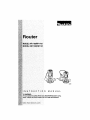
1
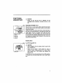
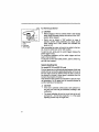
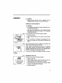
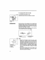
Router
MODEL RF1100/RF1101
MODEL RD1 IO0/RD1101
003_8
INSTRUCTION
MANUAL
_WARNING:
For your personal safety, READ and UNDERSTAND before using.
SAVE THESE INSTRUCTIONS FOR FUTURE REFERENCE,
www.makitatools.com
SPECIFICATIONS
Model
RFlf00! R_110,I RO_100
I AOlt0t
Collet chuck capacity
1/2" and 1/4"
ao,csdspeed(RP_l
2,,000/m*n
I9,_-2,,00_m,o
I 2,,00_m,n
t8=-2_,00_m,n
Overall height
223 turn (8-3/4")
Net weight
3.2 kg (7.1 Ibs)
I
3.6 kg (7.9 Ibs)
• Manufacturerreservesthe rightto changespecificationswithoutnotice,
• Specificationsmay differfrom countryto country.
GENERAL
SAFETY RULES
ue,0ol
2
(For All Tools)
A WARNING:
Read and understand
all instructions.
Failure to follow all
instructions listed below, may result in electric shock, fire and/or
serious personal injury.
SAVE THESE INSTRUCTIONS
Work Area
Electrical Safety
1.
Keep your work area clean and well lit.
Cluttered benches and dark areas invite accidents.
4.
2.
Do not operate
power tools
in explosive
atmospheres, such as in the presence of
flammable liquids, gases, or dust. Power
tools create sparks which may ignite the dust
or fumes.
3.
Keep bystanders,
children,
and visitors
away while operating a power tool. Distractions can cause you to lose control
Grounded tools must be plugged Into an
outlet properly installed and grounded in
accordance
with all codes
and ordi.
nancee.
Never
remove the grounding
prong or modify the plug in any way. Do
nut use any adaptor plugs. Check with a
qualified electrician ff you are in doubt as
to whether
the
outlet
is
properly
grounded. If the toots should electrically malfunction or break down, grounding provides a
low resistance path to carry electricity away
from the user.
5. Avoidbodycontact
with grounded surfaces such as pipes, rsdletom, ranges and
refrigerators. There is an increased risk of
electric shock if your body is grounded.
6.
7.
Do not expose power tools to rain or wet
conditions. Water entering a power tool will
increase the risk of electric shock.
Do not abuse the cord. Never use the cord
to carry the tools or pull the plug from an
outlet. Keep cord away from heat, o11,
sharp edges or moving parts. Replace
damaged
cords immediately.
Damaged
cords increase the risk of electric shock.
8.
When operating a power tool outside, use
an outdoor extension cord marked "W-A"
or "W". These cords are rated for outdoor
use and reduce the dsk of electric shock.
14. Use safety equipment. Always wear eye
protection.
Dust mask, non-skid safety
shoes, hard hat, or hearing protection must
be used for appropriate conditions. Ordinery
eye or sun glssses are NOT eye protection.
Tool Use and Care
15. Use clamps or other practical way to
secure and support the workpleca to s
stable platform. Holding the work by hand or
against your body is unstable end may lead
to loss of control.
16. Do not force tool. Use the correct tool for
your application. The correct tool will do the
job better and safer at the rate for which it is
designed,
17. Do not use tool if switch does not turn It
on or off. Any tool that cannot be controlled
Personal Safety
9.
Stay alert, watch what you are doing and
use common sense when operating a
power tool. Do not use tool while tired or
under the influence of drugs, alcohol, or
medication. A moment of inattention while
operating power tcols may result in serious
personal injury.
10. Dress properly. Do not wear loose clothing or jewelry. Contain long hair. Keep
your hair, ctothlng, and gloves away from
moving parts. Loose clothes, jewelry, or long
hair can be caught in moving parts,
11. Avoid accidental starting. Be sure switch
Is off before plugging in. Carrying tools with
your finger on the switch or plugging in tools
that have the switch on invites accidents.
12. Remove
adjusting
keys or wrenches
before turning the tool on. A wrench or a
key that is left attached to a rotating part of
the too[ may resul! in personal injury.
13. DO not overreach.
Keep proper footing
and balance at all times. Proper footing and
balance enables better control of the tool in
unexpected situations.
with the switch
repaired.
is dangerous and must be
18. Disconnect
the plug
source before making
from the power
any adjustments,
changing accessories, or storing the tool.
Such preventive safety measures reduce the
risk of starting the tool accidentally.
19. Store
Idle tools
out of reach of children
and other untrained persons.
Tools are
dangerous in the hands of untrained users.
20. Maintain tools with care. Keep cutting
tools sharp and clean. Propedy maintained
tools with sharp cutting edges ere less likely
to bind and are easier to control
21. Check for mlsallgnment
or binding of
moving parts, breakage of parts, and any
other condition that may affect the tools
operation. If damaged, have the tool serviced before using. Many accidents are
caused by poody maintained tools.
22. Use
only
accessories
that
are
recom-
mended by the manufacturer
for your
model. Accessories that may be suitable for
one tool, may become hazardous when used
on another tool.
3
SERVICE
23. Tool service must be performed only by
qualified repair personnel, Service or maintenance performed by unqualified personnel
could result in a risk of injury,
24. When servicing a tool, use only identical
replacement parts. Follow instructions in
the Maintenance section of this manual.
Use of unauthorized pails or failure to follow
Maintenance instructions may create a risk of
electric shock or injury,
USE PROPER EXTENSION CORD: Use only three-wire extension cords that have threeprong grounding-type plugs and three-pole receptacles that accept the tool's plug, Make
sure your extension cord is in good condition, Replace or repair damaged or worn cord
immediately. When using an extension cord, be sure to use one heavy enough to carry the
current your product wig draw. An undersized cord will cause a drop in line voltage resulting
in loss of power and overheating. Table 1 shows the correct size to use depending on cord
length and nameplate ampere rating. If in doubt, use the next heavier gage, The smaller the
gage number, the heavier the cord.
Table 1: Minimum gage for cord
Volts
Ampere Rating
120V
Total length of cord In feet
25ft.
More Than
Not More Than
0
6
18
6
10
18
10
12
16
12
16
14
I 5o.. I foo . I 1so..
AWG
16
16
16
12
16
14
14
12
14
12
Not Recommended
GROUNDINGtNSTRUC_ONS
This tool should be grounded while in use to protect the operator from electric shock. The
tool is equipped with a three-conductor cord and three-prong grounding type plug to fit the
proper grounding type receptacle. The green (or green and yellow) conductor in the cord is
the grounding wire. Never connect the green (or green and yellow) wire to a tire terminal,
Your unit is for use on 120 volts and has a plug that looks like Fig. "A",
4
An adapter Fig. "B" and "C= is available for connecting Fig. "A_ type plugs to two- prong
receptacles. The green-colored rigid ear, lug, etc., extending from the adapter must be connected to a permanent ground, such as a properly grounded outlet box.
Adapter
_Cover
of Grounde_'_
GroundingMeans
Outlet Box
Blade
Fig. A
SPECIFIC
Fig. B
SAFETY RULES
Fig, C
use013-3
DO NOT let comfort or familiarity with product (gained from
repeated use) replace strict adherence to router safety rules. If
you use this tool unsafely or incorrectly, you can suffer serious
personal injury.
1.
Hold tool by insulated gripping surfaces
when performing an operation where the
cutting tool may contact hidden wiring or
its own cord. Contact with a =live" wire will
6.
Hold the tool firmly with both hands.
7.
Keep hands away from rotating parts.
8.
Make sure the bit Is not contacting the
workplace baron= the switch is turned on.
9.
Before using the tool on an actual workpiece, let it run for a while, Watch for
vibration or wobbling that could indicate
improperly Installed bit.
make exposed metal parts of the tool "rive"
and shock the operator.
2.
Wear hearing protection
period of operation.
during extended
3.
Handle the bits very carefully.
4,
Check the bit carefully for cracks or damage before operation. Replace cracked or
damaged bit immediately.
5,
Avoid cutting
nails. Inspect
for and
remove all nails from the workplace
before operation.
10. Be careful o4=the hit rotating direction and
the feed direction.
11. Do not leave the tool running. Operate the
tool only when hand-held.
12. Always switch off and walt for the bit to
come to a complete stop before removing
the tool from workplace.
13.Donottouchthebit immediately
after
operation; it may be extremely
could burn your skin.
14. Always lead the power supply
from the tool towards the rear.
hot and
16. Draw attention to the need to use cutters
of the correct shank diameter and suitable
for the speed of the tool.
cord away
17. Some material
contains
chemicals
which
may be toxic. Take caution to prevent dust
inhalation and skin contact. Follow mate-
15. Do not smear the tool base carelessly with
dal supplier safety data.
thinner, gasoline, oil or the like. They may
cause cracks In the tool base.
SAVE THESE INSTRUCTIONS
/_ WARNING:
MISUSE
or failure to follow the safety rules stated
instruction manual may cause serious personal injury.
SYMBOLS
in this
uso,o,2
The followings
show the symbols used for tool.
V .......................
volts
_
A .......................
amperes
I"1, .................... no load speed
Hz .....................
hertz
................ alternating current
..Jmln ................ revolutions or reciprocation per
minute
FUNCTIONAL
DESCRIPTION
Ak CAUTION:
•
00365_
Always be sure that the tool is switched off and
unpluggedbefore adjustingor checkingfunction on the
tool.
Adjusting
the depth
of cut
Place the tool on a flat wood surface. Open the lock lever.
Turn the motor unit until the bit just touches the fiat surface.
Close the lock lever.
Rotate the scale ring until the zero-line is on the index line on
the motor unit. One graduation on the scale ring means the
cutting edge of the bit is exposed 1/64" below the base.
While holding up the base slightly, open the _ock lever and
turn the motor unit clockwise until the index line on the motor
unit reaches the desired depth indicated on the scale ring.
Close the lock lever firmly.
1. Motor unll housing
2. Index line
3. Scalering
4. Graduation
5. Locklever
Switch action
0C_861
For RF1100 and RF1101
,_
CAUTION:
Before plugging in the toot, always check to see that the
tool is switched off.
1. ev_tch lever
Switch can be locked in "ON" position for ease of
operator comfort during extended use. Apply caution
when locking tool in "ON" position and maintain firm
grasp on tool.
To start the tool, move the switch lever to the I (ON) position.
To stop the tool, move the switch lever to the 0 (OFF) position.
7
O03S_3
For RD1100 and RD1101
/k
•
Before plugging in the tool, always check to see that the
switch trigger actuates properly and returns to the "OFF"
position when released.
Switch can be locked in "ON" position for ease of
operator comfort during extended use. Apply caution
when locking tool in "ON" position and maintain firm
grasp on tool.
1. Motor unit cord
2. Outlet
3, Lockbutton
4. Switchtdgger
CAUTION:
After connecting the motor unit cord to the outlet in the handle, move the switch lever to the "ON" position.
To start the tool, simply pull the switch trigger. Re_ease the
switch trigger to stop.
For continuous operation, pull the switch trigger and then
push in the lock button.
To stop the tool from the locked position, pull the switch trigger fully, then release it.
Speed adjusting
dial
For model RF1101 and RD1101 only
The tool speed can be infinitely adjusted between 8,000 and
24,000 rpm by turning the speed adjusting dial on the top of
the tool. Higher speed is obtained when the dial is turned in
the direction of number 6; lower speed is obtained when it is
turned in the direction of number 1.
This allows the ideal speed to be selected for optimum material processing, i.e. the speed can be correctly adjusted to
suit the material and bit diameter.
/k CAUTION:
If the tool is operatedcontinuouslyat low speeds for a
longtime, the motorwill get overloaded,resultingin tool
malfunction.
•
The speed adjusting dial can be turned only as far as 6
and back to 1. Do not force it past 6 or 1, or the speed
adjusting function may no longer work.
ASSEMBLY
/K CAUTION:
Always be sure that the tool is switched off and
unplugged before carrying out any work on the tool.
Installing or removing the bit
,_ CAUTION:
Do not tighten the collet chuck without inserting a bit, or
the coUet chuck will break.
When using bit of bigger than 1-1/4" in diameter, install
base prate with center hole diameter 2-1/2", replacing
the original base plate.
OQ3672
First, remove the motor unit from the base as follows.
1. Open the fock lever.
2, While holding the base, turn the motor unit counterclockwise.
3. Turn it until the pin in the base is disengaged from the
groove in the motor unit. Lift the motor unit free from the
base.
Locklever
00367_
I
Insert the bit all the way into the co,et cone and tighten the
caller nut securely with the two wrenches.
These reuters accommodate the bits with 1/2" diameter
shank. When using the 1/4" diameter shank bit, replace the
equipped celiet chuck with the one for 1/4" diameter shank
bit which is provided as the standard accessory.
To remove the bit, follow the installation procedure in reverse.
1. Wrench
2. Router INt
0036?4
ReinstaLl the motor unit
Install the motor unit into the base as follows.
1. Open the lock lover.
2. While holding the base, insert the motor unit into the
base aligning the pin with the groove in the base.
Pin
3. Confirm that the pin and the groove are aligning. Rotate
the motor unit clockwise into the base.
4. Close the lock lever.
Forequippedwith switch-in-handle
®_TS For model RD1100 and RD1101 only
Connect the motor unit cord to the outlet in the handle.
1. Motor unit cord
2. Outlet
OPERATION
Set the tool base on the workpiece to be cut without the bit
making any contact. Then turn the tool on and wait until the
bit attains full speed. Move the tool forward over the workpiece surface, keeping the tool base flush and advancing
smoothly until the cutting is complete,
When doing edge cutting, the workpiece surface should be
on the _eft side of the bit in the feed direction.
001884
2
3
1, Workpiece
3. View fromthetop of the tool
2, Bit revolving direction
4. Feed direction
NOTE:
1. Feed direction
2. Bit revolving direction
3, Workp(ece
4, Straight guide
Moving the tool forward too fast may cause a poor
quality of cut, or damage to the bit or motor. Moving the
tool forward too slowly may burn and mar the cut. The
proper feed rate will depend on the bit size, the kind of
workpiece and depth of cut. Before beginning the cut on
the actual workpiece, it is advisable to make a sample
cut on a piece of scrap lumber. This will show exactly
how the cut will look as well as enable you to check
dimensions.
When using the straight guide, be sure to install it on the
right side in the feed direction. This will help to keep it
flush with the side of the workpiece.
10
.
0_78Straightguide(optionalaccessory)
Thestraight
guideis effectively used for straight
cuts when
chamfering or grooving.
_3sa2
To install the straight guide, insert the guide bars into the
holes in the tool base. Adjust the distance between the bit
and the straight guide. At the desired distance, tighten the
hex socket bolts to secure the straight guide in place.
When cutting, move the tool with the straight guide flush with
the side of the workpiece.
1. Hex socket botts
2. Guidebar
3. Straight guide
Templet
guide
(optional
accessory)
The templet guide provides a sleeve through which the bit
passes, allowing use of the tool with templet patterns.
0038B3
3
To install the templet guide, insert the templet guide in center
hole in the base plate and secure in place with the lock nut.
1. Lock nut
2. Templet guide
3, Base plate
4. Router bit
11
OO3896
Secure the templet to the workpiece.Place the tool on the
templet and move the tool with the templet guide sliding
alongthe side of the templet.
1. Router I_t
2. Base
3, Templet
4. Workplece
5, Templet guide
6. Lock nut
MAINTENANCE
A_ CAUTION:
• Always be sure that the tool is switched off and
unpluggedbefore attemptingto perform inspectionor
maintenance.
001145
Replacing carbon brushes
Remove and check the carbon brushes regularly.Replace
when they wear down to the limit mark. Keep the carbon
brushes clean and free to slip in the holders. Both carbon
brushesshouldbe replacedat the same time. Use onlyidenticalcarbon brushes.
Umitmark
OO3703
Use a screwdriver to remove the brush holder caps. Take out
the worn carbon brushes, insert the new ones and secure
the brush holder caps.
To maintain product SAFETY and RELIABILr_, repairs, any
other maintenance or adjustment should be performed by
Makita Authorized or Factory Service Centers, always using
Makita replacement parts.
Brush holder cap
Screwdriver
12
ACCESSORIES
,_, CAUTION:
• These accessoriesor attachmentsare recommendedfor
use with your Ma_ttatool specifiedin this manual. The
use of any other accessories or attachments might
presenta risk of injuryto persons.Only use accessory
or attachment for itsstatedpurpose.
If you need anyassistance for more detailsregardingthese
accessories,ask yourlocalMakita service center.
• Straight& grooveforming bits
Edge forming bits
Laminatetrimmingbits
•
Straightguide
•
Templetguides
Locknut
•
•
Clear base plate (Centerhole2-1/2")
Wrench 27
13
Memo
14
Memo
15
Memo
16
II
Makita U.S.A., Inc.
14930 Northam Street
La Mirada, CA 90638-5753
II,h,Lh,,,ll,,,,Ih h,l,,I,l,l,,,hhh,,ll,,h,II
L._
Fold .......................................................
MAIL THIS PORTION
Your answers to the following
1.This
product wn
pumhltsed
[]
Home Center
[]
Hardware,_..umber
]Tool
questions
are appreciated.
from:
3. How did you learn about this prOduCt:
[]
[]
Magazine
[]
Radio
[]
From Dealer
[]
Exhibition
[]
Newspaper
[]
From Friend
Store Disptay
[]
Previous Usage
Other(
Store
Distributor
[]
Indusb'ial SUpPly
[]
]
Constrvction Supply
[] c..talog
2. Use of the product
[]
is intended
for:
[] c,h._(
4. Most f_red
Construction Trade
[]
points
are;,
Design
[]
Repair Ser'4ce
[] In,_.t.,.I
M=i.te.,,,,==
[] Feat.r.
[] D.r_i,V
[]
Home Maintenance
[]
Size
[]
Power
[]
Hobby
[]
Price
[]
Otbsr (
5. Any comments:
DATEPURCHA_ED
MODELNO.
MONTH
DAY
_-_
YEAR
_
_'_
SERIAl_NO.
STATUS
INTL
LAST NAME I COMPANY
NAME
I
STREET
SEX
M.lU_ed SJn_e
I
M
I
ADRESS
DFFY
AREA
STATE
AGE:
BE SURE
ZIP ODDS
[_]
U_der 19
TO COMPLETE
Please
_"_
PHDNE
20-29
THE CUSTOMER'S
return
_]
3Q-39
PORTION
OF THIS
[_
40-49
FORM
CODE
_]
AND RETAIN
this portion by facsimile
FacsimiLe No: (714) 522-8133
50-60
[]
FOR YOUR
or mail.
Over 60
RECORDS.
F
FACTORY SERVICE CENTERS
1-800-4-MAKITA
RETAIN
THIS
PORTION
FOR YOUR
ARIZONA
3707 E. Em:_tdVd_
Rd, Ste 6
phoenix,AZB$040
(S02)_7-_50
FLORIDA
750 ¢.aslSam_ Road
PompanoBeth, FL.33064
(_54) 781-6333
RECORDS
MISSOURI
9E7E Ws_r_ Road
St Louil, MO 6312S-2221
(314) _
pENNSYI_VANIK
1704 I_abco(_ Ellvd.
pltlab_rgh,PA 15209
(412) 822-7370
CALIFORNIA
GEORGIA
NEBRASKA
PUERTO
411550 Chr41y St.
Fmmor_ CA 94538-5107
(510) 657-gB8_
4E,80 Rl'*_r Green padotmy NW
[:qJlulh, _ 300_3
(770047_-Bgl
1
412S S 84th St,
Omaha, N_ 68127
(402) 5_7- _J)25
_0 _ayam=
5_
Hato R_I I:_ 00917
(7B7) 250-8776
14930 NO_hLm St
La M_da,
CA _._5753
(714) 522-aOSB
g.LJNOIS
1450 Flehanvt_
NEVADi_
3375 S. Decat L;r E6vd.
TENNESSEE
1120 Elm H_
Suites. 22 • 24
_
',_gaSl N_ B_102
(7O2) 36_-_277
5ulle 170 Nuhvtlll,
(615) 248-3321
Dr,
Mt. prospect, IL 60056-6011
(847_ 2_7-3_00
1D70 Fullon A_L_e
Sacm.m_o,
CA E#387.5
RICO
TN 372
(9100 482-5197
MARYLAND
7_7 W'a_lngtc=1_o_lm._ff,
S_te 104 Elkddg_ MD 21075
(410) 796-4401
?674 Clalrs,tilont Me,l_ Blvd.
D,_go, CA 9211_
(SSal278-4471
16735 SatlcoySt, _e. 105
Van Nt,y_ CA 91_)6
(818) 782.2440
MA_S_IUSEITS
232 PreValenceHwy
_o00
MA 02090
(751) 461-9754
COLORADO
_183_ E 51st AW*.
Denver, CO 80239-2700
(_2) _1.285o
CUSTOMER'S
MIr_INF_OTA
6427 Penn A'_e So_th
RIch;i_,
MN 5$423
(812) 8,69-519_
NEW JERSEY
251 Hetrod B_.d.
Dayton.NJ 0_1_-1S3_
(609) 6S5=_2t2
NEWYORK
4817 Ger'_r_ee S_reet
C_mr_1o,_q_g_
NY 14225
(716) 685-95O3
OREGON
828 191h A,_nu|, N.W.
_d,
OR 9720_
(5O3) 222_182_
TEXAS
t2801 _mnlor_
FwySt=. 80_
Farriers Bnmch,13( 75234
(972) 243-1150
12701 Oim_tcrliOr.
Si_r._rd,33€ 7747"1-3701
(2BI 1_65-_6S5
345_ IH.35 NorlhI S_e 101
San Antonio,33(7821 g
(21O)225-0676
W_SCONS_N
Lin_tn putza ,_:_op_plng _tr.
224_ _ 10BtJl_LWe_ i_i_ W1
532_/
(414) 541-4776
RECORD
_n
_u need em'_lce: S_d
c=ndee tool(p_)to
o_e
Da_e Purchased
ofthe Maldta F_ory Service
Dealer's Name & Address
CerrtersF=_e_,or 2) _n ,e4_hofized
Maklt=Servic_Center.Be sum
toa_ch a I_e_ 00theo_d_
of
_*=e_rton detailingthepro_em
_u_ tool
_odal
No,
Serial No
19
WARNING
Some dust created by power sanding, sawing, grinding, drilling, and other
construction activities contains chemicals known to the State of California
to cause cancer, birth defects or other reproductive harm. Some examples
of these chemicals are:
• lead from lead-based paints,
• crystalline silica from bricks and cement and other masonry products, and
• arsenic and chromium from chemically-treated lumber.
Your risk from these exposures varies, depending on how often you do this
type of work. To reduce your exposure to these chemicals: work in a well
ventilated area, and work with approved safety equipment, such as those
dust masks that are specially designed to filter out microscopic particles.
MAKITA LIMITED ONE YEAR WARRANTY
Warranty Policy
Every Makita tool Is thoroughly inspected and tested before leaving the factory, it is warranted to be free of
defects from workmanship and mstedals for the period of ONE YEAR from the date of original purchase.
Should any trouble develop during this one year pedod, return the COMPLETE tobl, freight prepaid, to one of
Makita's Factory or Authorized Service Centers. if ]nspection shows the trouble is caused by defective
workmanship or msteriai, Makita will repair (or at our option, replace) without charge.
This Warranty does not apply where:
• repairs have been made or attempted
by others:
• repairs are required because of normal wear and tear:
• the tool has been abused, misused or improperly
maintained:
• aiferaif ons have been made to the tool.
iN NO EVENT SHALL MAKITA BE LIABLE FOR ANY INDIRECT, INCIDENTAL OR CONSEQUENTIAL
DAMAGES FROM THE SALE OR USE OF THE PRODUCT. THIS DISCLAIMER APPLIES BOTH DURING
ANC AFTER THE TERM OF THIS WAR RANTY.
MAKITA DISCLAIMS
"MERCHANTABILITY"
WARRANTY.
LIABILITY FOR ANY IMPLIED WARRANTIES, INCLUDING IMPLIED WARRANTIES OF
AND "FITNESS FOR A SPECIFIC PURPOSE," AFTER THE ONE YEAR TERM OF THIS
This Warranty gives you specific legal fights, and you may also have other rights which vary from state to state.
Some states do nut allow the exclusion or limitation of incidental or consequential damages, so the above
limitation or exbluaicn may nut apply to you. Some states do nut allow limitation on how long an implied
warranty lasts, so the above limitation may not apply to you.
Makita Corporation
of America
2650 Buford Hwy., Buford, GA 30518
884304C068