1
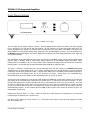
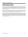
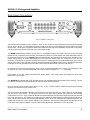
Owner’s Manual MOON Series i 5.3 Integrated Amplifier MOON i 5.3 Integrated Amplifier Important Safety Instructions 1. Read these instructions. 2. Keep these instructions. 3. Heed all warnings. 4. Follow all instructions. 5. Do not use this apparatus near water. 6. Clean only with a dry cloth. 7. Do not block ventilation openings. Install in accordance with the manufacturer’s instructions. 8. Do not install near any heat sources such as radiators, heat registers, stoves or another apparatus that produces heat. 9. Do not defeat the safety purpose of the polarized or grounding type plug. A polarized plug has two blades with one wider than the other. A grounding-type plug has two blades and a third grounding prong. The wide blade or the third prong is provided for safety. If the provided plug does not fit into the outlet, consult an electrician for replacement of the obsolete outlet. 10. Protect the power cord from being walked on or pinched, particularly at plugs, convenience receptacles, and the point where they exit from the apparatus. 11. Only use attachments and accessories specified by the manufacturer. 12. Use only with the cart, stand, tripod, bracket, or table specified by the manufacturer or sold with the apparatus. When a cart is used, use caution when moving the cart/apparatus combination to avoid injury from tip over. 13. Unplug this apparatus during lightning storms or when unused for long periods of time. 14. Refer all servicing to qualified service personnel. Servicing is required when the apparatus has been damaged in any way, such as when the power cord or plug has been damaged; liquid has been spilled or objects have fallen into the apparatus; or the apparatus has been exposed to rain or moisture, does not operate normally, or has been dropped. 15. No naked flame sources, such as candles, should be placed on the apparatus. WARNING: TO REDUCE THE RISK OF FIRE OR ELECTRIC SHOCK, DO NOT EXPOSE THIS APPLIANCE TO RAIN OR MOISTURE. ____________________________________________________________________________________ MOON i 5.3 Integrated Amplifier Important Safety Instructions (cont’d) The lightning flash with the arrowhead symbol, within an equilateral triangle, is intended to alert the user to the presence of uninsulated “dangerous voltage” within the product’s enclosure that may be of sufficient magnitude to constitute a risk of electric shock to persons. The exclamation point within an equilateral triangle is intended to alert the user to the presence of important operating and maintenance (servicing) instructions in the literature accompanying the appliance. Marking by the “CE” symbol (shown left) indicates compliance of this device with the EMC (Electromagnetic Compatibility) and LVD (Low Voltage Directive) standards of the European Community Please read all instructions and precautions carefully and completely before operating your Simaudio MOON i 5.3 Integrated Amplifier. 1. ALWAYS disconnect your entire system from the AC mains before connecting or disconnecting any cables, or when cleaning any component. 2. The MOON i 5.3 must be terminated with a three-conductor AC mains power cord which includes an earth ground connection. To prevent shock hazard, all three connections must ALWAYS be used. Connect the MOON i 5.3 only to an AC source of the proper voltage; Both the shipping box and rear panel serial number label will indicate the correct voltage. Use of any other voltage will likely damage the unit and void the warranty 3. AC extension cords are NOT recommended for use with this product. 4. NEVER use flammable or combustible chemicals for cleaning audio components. 5. NEVER operate the MOON i 5.3 with any covers removed. There are no user-serviceable parts inside. An open unit, especially if it is still connected to an AC source, presents a potentially lethal shock hazard. Refer all questions to authorized service personnel only. 6. NEVER wet the inside of the MOON i 5.3 with any liquid. If a liquid substance does enter your MOON i 5.3, immediately disconnect it from the AC mains and take it to your MOON dealer for a complete check-up. 7. NEVER spill or pour liquids directly onto the MOON i 5.3. 8. NEVER block air flow through ventilation slots or heatsinks. 9. NEVER bypass any fuse. 10. NEVER replace any fuse with a value or type other than those specified 11. NEVER attempt to repair the MOON i 5.3. If a problem occurs contact your MOON dealer. 12. NEVER expose the MOON i 5.3 to extremely high or low temperatures. 13. NEVER operate the MOON i 5.3 in an explosive atmosphere. 14. ALWAYS keep electrical equipment out of reach of children. 15. ALWAYS unplug sensitive electronic equipment during lightning storms. ____________________________________________________________________________________ MOON i 5.3 Integrated Amplifier Table of Contents Congratulations ............................................... 5 Unpacking and Warnings ................................... 5 Introduction .................................................... 6 Installation & Placement ................................... 6 Front Panel Controls ......................................... 7 Rear Panel Connections ..................................... 9 Operating the i 5.3 ..........................................10 Remote Control Operation ................................11 Specifications .................................................12 www.simaudio.com Revision no.: 20091110 ____________________________________________________________________________________ MOON i 5.3 Integrated Amplifier Congratulations! Thank you for selecting the MOON i 5.3 Integrated Amplifier as a part of your music/cinema system. This component has been designed to offer state-of-the-art high-end performance in an elegant package, while retaining all the sonic hallmarks on which Simaudio has made its reputation. We have spared no effort to ensure that it is amongst the finest two-channel Integrated Amplifier available. We have been building high-performance audio equipment for over 25s years, and the know-how gained through our cumulative experience is an important reason why MOON integrated amplifiers are so musically satisfying. The performance of your i 5.3 will continue to improve during the first 400 hours of listening. This is the result of a “break-in” period required for the numerous high quality electronic parts used throughout this integrated amplifier. Before setting up your new MOON i 5.3, we encourage you to please read this manual thoroughly to properly acquaint yourself with its features. We hope you enjoy listening to the MOON i 5.3 integrated amplifier as much as the pride we have taken in creating this fine audio product. We understand the power and emotion of music and build our products with the goal of faithfully capturing these elusive qualities. The information contained in this manual is subject to change without notice. The most current version of this manual is available on our official website at http://www.simaudio.com/manuals.htm Unpacking The MOON i 5.3 integrated amplifier should be removed from its box with care. The following accessories should be included inside the box with your integrated amplifier: 9 AC power cable 9 ‘SRM’ remote control with three ‘AAA’ batteries (USA and Canada only) 9 Four (4) pointed screw-on tips (for the Integrated Amplifier’s legs) 9 Four (4) protective flat dimpled discs to be placed under the screw-on cones 9 This owner’s manual 9 Warranty and product registration information (USA and Canada only) As soon as the integrated amplifier is safely removed from its box and placed down, perform a thorough physical inspection and report any physical damage to your dealer immediately. We suggest that you keep all of the original packaging, storing it in a safe, dry place in the event that you’re required to transport the integrated amplifier. The customized packaging is specially designed to protect the MOON i 5.3 integrated amplifier from potential damage that may occur during shipping. Please write the serial number of your new Simaudio MOON i 5.3 in the space provided below for future reference. Serial No.: ________________ ____________________________________________________________________________________ Congratulations / Unpacking 5 MOON i 5.3 Integrated Amplifier Introduction Your MOON i 5.3 integrated amplifier incorporates many significant design features to achieve its “world class” level of performance. This is an abbreviated list of the more important features: Proprietary “Advanced Renaisance” Technology which eliminates feedback. The results are as follows: Real-time amplification is achieved since interactions from the speaker back to the amplifier are virtually eliminated; More accurate musical reproduction with respect to tonality; Virtually non-existent transient intermodulation distortion (which is far more degrading to sonic perfomance than harmonic distortion); The elimination of common phase errors resulting from feedback. An oversized power supply using a custom proprietary toroidal transformer design with lower magnetic, electrical and thermal loss, yielding an improved transfer and lower regulation factor, resulting in increased current speed and better dynamics. An extremely short capacitor-free signal path measuring only fifteen inches in length, from input RCA connectors to output binding posts, for a faster transient response. Class “A” preamplifier section circuit topology. A gain section that uses a Crystal microprocessor functioning as a “shunt to ground” that doesn't degrade sonic performance regardless of the selected setting. J-FET input devices in the preamplifier section. Precision matched Bipolar output devices, in the amplifier section, which offer superb linearity throughout the entire audio frequency spectrum. IR input for external control. One single-ended audio input which functions as a “pass-through”, bypassing the gain stage to accommodate a component such as a home-theater processor, whose own volume control is used instead. Extremely rigid chassis construction to minimize the effects of external vibrations. A symmetrical circuit design with accurate matching of the very finest high quality electronic components. Pure copper circuit board tracings with extremely low impedance characteristics. Designed to be powered up at all times for optimal performance. Low operating temperature for a longer than normal life expectancy. Installation & Placement The MOON i 5.3 requires reasonable ventilation to maintain an optimum and consistent operating temperature. As a result, it should be placed in a location with empty space around it for proper heat dissipation. As well, it should be placed on a solid level surface. You should avoid placing it near a heat source or inside a closed cabinet that is not well ventilated as this could compromise this component’s performance and reliability. The i 5.3 uses a toroidal transformer; even though it is well shielded, you should not place the integrated amplifier too close to source components sensitive to EMI, such as turntables and phono preamplifiers. You should never place another component directly on top of this integrated amplifier. Once you’ve decided on a location for the i 5.3, you should install the four (4) pointed screw-on tips into the four (4) cylindrical legs of the chassis. These tips will easily scratch most surfaces, therefore it’s advisable to follow these instructions: Place your i 5.3 on a soft surface (i.e. carpet) and carefully turn it so that it rests on its side. Screw one tip into each of the four legs. Carefully move the chassis to it’s pre-determined location. In the event that the surface you have chosen isn’t perfectly level, each of the four (4) tips on your i 5.3 are height adjustable; Included with these tips is a small metal rod, intended for final adjustments (if necessary) by simply threading it through the tiny hole of each of these tips and then gently turning the tip. These adjustable screw-on tips also provide mechanical grounding of the chassis. ____________________________________________________________________________________ Introduction / Installation & Placement 6 MOON i 5.3 Integrated Amplifier Front Panel Controls Figure 1: MOON i 5.3 Front panel The front panel will look similar to Figure 1 (above). The large display window indicates the relative gain setting (ranging from ‘0’ through ‘50’) for both the left and right channels. As well, whenever you change the selected input source, it’s number will appear in the window for 3 seconds before reverting back to the gain setting. Immediately to the right of the display window is a button labeled “Display” which allows you to turn the digital display on and off. The sonic performance of the MOON i 5.3 integrated amplifier may improve slightly when the display is turned off simply because the power supply has one less task to perform. The “Standby/On” button disengages the input section from the rest of the i 5.3’s circuitry and turns off the digital display. However, when in “Standby” mode all audio circuitry remains powered up to help maintain optimal performance. When switching back from “Standby” to the “on” mode, both the ‘input’ and gain level settings will be memorized from the previous listening session. The blue pilot LED will not be illuminated when the i 5.3 is in “Stand by” mode. The “Input +” and “Input -” buttons allow you to choose which input source you wish to listen to. The MOON i 5.3 integrated amplifier has five (5) inputs labeled CD, A1, A2, A3, and A4. Assuming that you’re currently listening to a source component connected to the CD input, pressing the “Input +” selector button allows you to sequentially scroll forward through each of the possible inputs in the following order: CD, A1, A2, A3 and A4. The “Input -” button allows you to sequentially scroll backwards through each of the possible inputs in the following order; A4, A3, A2, A1 and CD. The A4 input can be configured as a ‘pass-through’ which bypasses the i 5.3’s gain control section, allowing you to control the gain setting via the connected source component’s own volume control – a home theater processor for example. In ‘passthrough’ mode, adjusting the volume on the i 5.3 will have no effect whatsoever when the A4 input is selected. To put the A4 input into ‘pass-through’ mode, simply press and hold down the “Mute” button for approximately 5 seconds; you don’t have to be on the A4 setting to do this. To reconfigure the A4 input to function like the four (4) other inputs, repeat the aforementioned procedure. As well, powering down the i 5.3 via the rear panel rocker switch will reset the the A4 to the factory default ‘normal’ mode. Holding down either the “Input +” or “Input -“ button will allow only a single change of the selected input. You must press the button again to select the next or previous input. The “Mute” button reduces the current volume to “0”. Pressing the “Mute” button a second time will reinstate the volume back to its previous level. ____________________________________________________________________________________ Front Panel Controls 7 MOON i 5.3 Integrated Amplifier Front Panel Controls (continued) The rotary “Volume” control determines the gain setting, which ranges from ‘0’ (no output) to ‘50’ (full output). This control doesn’t function like a typical volume: When you rotate the dial, either clockwise for more gain or counter-clockwise for less gain, you are actually engaging a high quality optical encoder which selects a specific gain setting on a shunt-to-ground based microprocessor circuit. This gain circuit, known as RGB-cs, doesn’t degrade the audio signal regardless of the setting, unlike all potentiometer based circuits. Since there are no actual moving parts, this proprietary gain technology has a minimum life expectancy of one million rotations. The range of fifty (50) unique gain settings is based on neither a linear nor logarithmic scale. Instead, we decided on relatively small variations for each of the lower position settings from ‘1’ to ‘35’. The variations are somewhat larger from positions ‘36’ through ‘50’. For the best possible performance, it is recommended that you don’t turn the rotary control too quickly as some gain settings will be skipped and extra rotations will be required to reach position ‘50’. Between the left and right channel gain settings indicators appearing in the display window, is a red LED which functions as a status indicator. If a problem is ever detected with the i 5.3’s internal circuitry, this LED will illuminate, even if the problem originates from the source component currently in use. In the event that the LED remains on, you should immediately power down your i 5.3 using the main power switch located on the rear panel, then contact your dealer for service. Don’t confuse this with a smaller red LED, located directly to the bottom right of the left channel’s gain setting indicator which will faintly illuminate whenever the i 5.3 receives an infra-red (IR) signal from a remote control; This simply confirms the successful reception of the IR remote signal. ____________________________________________________________________________________ Front Panel Controls 8 MOON i 5.3 Integrated Amplifier Rear Panel Connections Figure 2: MOON i 5.3 Rear panel The rear panel will look similar to Figure 2 (above). There are five (5) pairs of single-ended inputs on RCA connectors labeled CD, A1, A2, A3 and A4. The left channel inputs are located on top and the corresponding right channel inputs are located directly below. The A4 input, as previously mentioned, bypasses the gain stage and is intended to be used with a component, such as a home theater processor, that has its own volume/gain control. The MOON i 5.3 integrated amplifier has two pairs of non-amplified outputs; One single-ended pair of RCA connectors labeled ‘Pre Out’, located next to the A4 input, is designated for output to a power amplifier with single-ended RCA inputs in the event that you wish to use your MOON i 5.3 as a preamplifier only. The output level of the ‘Pre Out’ is dependant on the volume control setting. A second single-ended pair if RCA connectors labeled ‘Tape Out’, located next to the ‘Pre Out’ connectors, is intended as an input to a recording device such as a cassette tape deck or CD-Recordable Player. Keep in mind that the output level on the ‘Tape Out’ is fixed and cannot be adjusted by the i 5.3’s volume control. All RCA input and output connectors on the rear panel have been color coded: ‘white’ for the left channel and ‘red’ for the right channel. On each side of the group of RCA connectors, there is a pair of gold-plated binding posts. Connect your loudspeakers, with the cables of your choice, to these binding posts. Take care to respect the polarity (“+” , “-” ) of the output. Don’t hesitate to use high quality interconnects and speaker cables. performance of your system. Poor quality cables can degrade the overall sonic Your MOON i 5.3 is equipped with a 1/8” mini-jack input for use with aftermarket infrared remote control receivers. The “IR in” connector is located on the far left side directly above the serial number information. Finally on the right side is the main power switch (“0”=off, “1”=on), the IEC receptacle, labeled “AC Input” for the included AC power cord, and the “AC Fuse” socket cover. You will notice that all RCA input and output connectors on the rear panel have been color coded: ‘white’ for the left channel and ‘red’ for the right channel. All rear panel connectors have been chosen because they provide the best possible connections for your unit. A poor contact will degrade the signal substantially, and plugs and sockets should all look clean and free of dirt and corrosion. The easiest way to clean them is to remove the cables from their sockets and push them back in again. This procedure requires that your Integrated Amplifier and the rest of your components be completely turned off. Not heeding this warning may result in serious damage to your equipment. Special contact cleaning fluids and enhancers should not be used, as they deposit a difficult to remove residue which degrades the performance of your components. ____________________________________________________________________________________ Rear Panel Connections 9 MOON i 5.3 Integrated Amplifier Operating the i 5.3 We recommend that you leave your MOON i 5.3 Integrated Amplifier powered up at all times to maintain optimal performance. In the event that you plan to be away from your home for a few days, powering off the Integrated Amplifier may not be a bad idea. Once fully “broken-in”, please keep in mind that your i 5.3 will require several hours of playing time before it reaches its peak performance after you’ve powered it up again. Making the AC Connection Connect the supplied AC power cable to the IEC receptacle, located on the rear panel of the integrated amplifier’s chassis. Ensure that the AC wall outlet you use has a functioning ground. For the best sonic performance, it is preferable that you plug your MOON i 5.3 directly into a dedicated AC outlet and avoid using an extension cord. In order to obtain the maximum performance from your audio system, we strongly recommend that the detachable power cord not come into physical contact with any of the interconnect and speaker cables running to and from your i 5.3. In the event that this can’t be avoided, you should ensure that any cables coming into contact with each other are crossed at ninety degree angle to minimize the contact area. Turning on your MOON i 5.3 for the first time Prior to turning the integrated amplifier on for the first time, make sure that every cable is properly connected to avoid any problems. Then turn on your integrated amplifier in the following manner: 1) Flick the main rocker switch labeled “POWER” to the ‘1’ (on) position on the rear of the i 5.3. 2) Press the push button labeled “Stand by/On” on the i 5.3s front panel. The blue LED will illuminate and the digital display will indicate a gain setting of ‘0’ and the ‘CD’ as the default input. On and Off Sequence To avoid having any annoying noises (ie. “thumps” and “pops”) emanate from your speakers when powering your i 5.3 on or off, you should 1) Always power up your i 5.3 integrated amplifier after powering up your source component(s).] 2) Always power down your i 5.3 before powering down your source component(s). ____________________________________________________________________________________ Operating the i 5.3 10 MOON i 5.3 Integrated Amplifier Remote Control Operation The MOON i 5.3 Stereo integrated amplifier uses the ‘FRM-2’ full function, all aluminum remote control (figure 4). It operates on the Philips RC-5 communication protocol and can be used with other MOON components. The ‘FRM-2’ remote uses three AAA batteries (included). To install them, use the supplied Allen key to remove the three screws located on the back plate; insert the batteries in the correct direction and then screw the back plate back into place. The POWER button located on the upper left will switch the integrated amplifier to either ‘Stand by’ or ‘On’ mode. The INPUT button performs in exactly the same way as the ‘Input’ button located on the i 5.3’s front panel, sequentially cascading through each of the integrated amplifier’s inputs. The VOL+ and VOL– buttons increase and decrease, respectively, the volume level. The and buttons control channel balance; Pressing the left arrow button causes a decrease in the volume level of the right channel; pressing the right arrow button causes a decrease in the volume level of the right channel. The MUTE button, located in the middle of the volume and balance buttons, performs the identical function as the ‘Mute’ button located on the i 5.3’s front panel. Figure 3: FRM-2 Remote Control ____________________________________________________________________________________ Remote Control Operation 11 MOON i 5.3 Integrated Amplifier Specifications Configuration ......................................................... Power Supply Transformer ....................................... Power Supply Capacitance ...................................... Class Of Operation - Preamplifier .............................. Class Of Operation - Amplifier .................................. Single-ended inputs ................................................. Input Device Type - Preamplifier .............................. Input Sensitivity ..................................................... Input Impedance ................................................... Tape Output .......................................................... Preamplifier output ................................................. Output Device Type - Amplifier ................................ Output Binding Posts ............................................... Output Power @ 8Ω ................................................ Output Power @ 4Ω ................................................ Output Impedance .................................................. Damping Factor ...................................................... Gain Control ........................................................... Gain ....................................................................... Dynamic Headroom ................................................. Signal-to-noise Ratio .............................................. Maximum Output Voltage ........................................ Slew Rate ............................................................... Maximum Current – Peak ........................................ Maximum Current – Continuous .............................. Frequency Response .............................................. Crosstalk @ 1kHz ................................................... Intermodulation Distortion ...................................... THD (20Hz - 20kHz @ 1 watt) ................................ Remote Control ...................................................... AC Power Requirements ......................................... Shipping Weight ..................................................... Dimensions (W x H x D, inches) .............................. Fuse Replacement: Dual-Mono (Partial) 0.5kVA 40,000µF Class A Class A/B 5 (RCA) J-FET 370mV – 3.0V RMS 14,000Ω 1 (RCA) 1 (RCA) Bipolars – 2 per channel WBT 85 Watts per channel 130 Watts per channel 0.04Ω > 200 RGB cs – “Shunt-To-Ground” 37dB 6dB 97dB @ full power 25 Volts 20V/µs 18 amperes 10 amperes 10Hz - 70kHz +0/-3dB -50dB Unmeasureable < 0.1% All Aluminum Simple-Function (SRM) 120V / 60Hz or 240V / 50Hz 28 lbs / 13 Kgs 17 x 4 x 15 For the 120V version use a 4A fast blow (3AG size). For the 230V version use a 2A fast blow (3AG size). ____________________________________________________________________________________ Specifications 12