1
5
Máquina overlock SON 90 A1
Tagliacuci
new
Máquina overlock
Instrucciones de uso
Tagliacuci
Istruzioni per l‘uso
Máquina de costura „Overlock“
Manual de instruções
KOMPERNASS GMBH
BURGSTRASSE 21 · D-44867 BOCHUM
www.kompernass.com
ID-Nr.: SON 90 A1-01/10-V4
Overlock Sewing Machine
Operating instructions
Overlock-Nähmaschine
Bedienungsanleitung
SON 90 A1
i
o
1
p
a
r
t
z
u
s
2
d
3
4
f
5
e
w
q
6
7
8
9
0
ÍNDICE
PÁGINA
Uso conforme al previsto
3
Indicaciones de seguridad
3
Volumen de suministro
4
Datos técnicos
4
Descripción de aparatos
5
Colocar la cuchilla superior en posición de reposo
5
Informaciones de agujas
5
Aplicación lanzadera
5
Abrir tapa frontal
6
Preparativos
6
Conectar el pedal . . . . . . . . . . . . . . . . . . . . . . . . . . . . . . . . . . . . . . . . . . . . . . . . . . . . . . . . . . . . . . . . . . . . . . . . . . . . . . . . . . . . . . . . . . . . .6
Controlar la velocidad de costura . . . . . . . . . . . . . . . . . . . . . . . . . . . . . . . . . . . . . . . . . . . . . . . . . . . . . . . . . . . . . . . . . . . . . . . . . . . . . . . . .6
Interruptor de seguridad . . . . . . . . . . . . . . . . . . . . . . . . . . . . . . . . . . . . . . . . . . . . . . . . . . . . . . . . . . . . . . . . . . . . . . . . . . . . . . . . . . . . . . . .6
Colocar el depósito de residuos . . . . . . . . . . . . . . . . . . . . . . . . . . . . . . . . . . . . . . . . . . . . . . . . . . . . . . . . . . . . . . . . . . . . . . . . . . . . . . . . . .6
Retirar aguja(s) . . . . . . . . . . . . . . . . . . . . . . . . . . . . . . . . . . . . . . . . . . . . . . . . . . . . . . . . . . . . . . . . . . . . . . . . . . . . . . . . . . . . . . . . . . . . . . . .7
Insertar aguja(s) . . . . . . . . . . . . . . . . . . . . . . . . . . . . . . . . . . . . . . . . . . . . . . . . . . . . . . . . . . . . . . . . . . . . . . . . . . . . . . . . . . . . . . . . . . . . . . .7
Manejar la rueda manual . . . . . . . . . . . . . . . . . . . . . . . . . . . . . . . . . . . . . . . . . . . . . . . . . . . . . . . . . . . . . . . . . . . . . . . . . . . . . . . . . . . . . . .7
Ajuste del árbol de hilos . . . . . . . . . . . . . . . . . . . . . . . . . . . . . . . . . . . . . . . . . . . . . . . . . . . . . . . . . . . . . . . . . . . . . . . . . . . . . . . . . . . . . . . .7
Enhebrar
8
Indicaciones generales para enhebrar . . . . . . . . . . . . . . . . . . . . . . . . . . . . . . . . . . . . . . . . . . . . . . . . . . . . . . . . . . . . . . . . . . . . . . . . . . . . .8
Enhebrado áncora superior (rojo) . . . . . . . . . . . . . . . . . . . . . . . . . . . . . . . . . . . . . . . . . . . . . . . . . . . . . . . . . . . . . . . . . . . . . . . . . . . . . . . . .8
Enhebrado áncora inferior (amarillo) . . . . . . . . . . . . . . . . . . . . . . . . . . . . . . . . . . . . . . . . . . . . . . . . . . . . . . . . . . . . . . . . . . . . . . . . . . . . .10
Enhebrado de hilo para aguja derecha (verde) . . . . . . . . . . . . . . . . . . . . . . . . . . . . . . . . . . . . . . . . . . . . . . . . . . . . . . . . . . . . . . . . . . . .11
Enhebrado de hilo para aguja izquierda (azul) . . . . . . . . . . . . . . . . . . . . . . . . . . . . . . . . . . . . . . . . . . . . . . . . . . . . . . . . . . . . . . . . . . . . .13
Funcionamiento de prueba . . . . . . . . . . . . . . . . . . . . . . . . . . . . . . . . . . . . . . . . . . . . . . . . . . . . . . . . . . . . . . . . . . . . . . . . . . . . . . . . . . . . .14
Cambio de hilo (anudar)
15
Ajuste de la longitud de puntada
15
Ajuste del ancho de puntada
15
...usando la aguja derecha o bien izquierda . . . . . . . . . . . . . . . . . . . . . . . . . . . . . . . . . . . . . . . . . . . . . . . . . . . . . . . . . . . . . . . . . . . . . . .15
... girando el botón de regulación de ancho de puntada . . . . . . . . . . . . . . . . . . . . . . . . . . . . . . . . . . . . . . . . . . . . . . . . . . . . . . . . . . . . .16
Ajuste del botón de regulación de ancho de puntada . . . . . . . . . . . . . . . . . . . . . . . . . . . . . . . . . . . . . . . . . . . . . . . . . . . . . . . . . . . . . . .16
Ajuste de la presión del prensatelas
16
Transporte diferencial
17
Modo de funcionamiento . . . . . . . . . . . . . . . . . . . . . . . . . . . . . . . . . . . . . . . . . . . . . . . . . . . . . . . . . . . . . . . . . . . . . . . . . . . . . . . . . . . . . .17
Ajustes - costura Overlock fruncida . . . . . . . . . . . . . . . . . . . . . . . . . . . . . . . . . . . . . . . . . . . . . . . . . . . . . . . . . . . . . . . . . . . . . . . . . . . . . .17
Costura overlock estirada - Ajustes . . . . . . . . . . . . . . . . . . . . . . . . . . . . . . . . . . . . . . . . . . . . . . . . . . . . . . . . . . . . . . . . . . . . . . . . . . . . . . .17
Costura de brazo libre
18
Lea atentamente este manual de instrucciones antes del primer uso y consérvelo para posteriores utilizaciones. Entréguelas en caso de traspasar el
aparato a terceros.
-1-
Costuras overlock
19
Dobladillos enrrollados . . . . . . . . . . . . . . . . . . . . . . . . . . . . . . . . . . . . . . . . . . . . . . . . . . . . . . . . . . . . . . . . . . . . . . . . . . . . . . . . . . . . . . . .19
Fijar las mallas y costura de prueba . . . . . . . . . . . . . . . . . . . . . . . . . . . . . . . . . . . . . . . . . . . . . . . . . . . . . . . . . . . . . . . . . . . . . . . . . . . . . .20
Ajustes de tensado recomendados . . . . . . . . . . . . . . . . . . . . . . . . . . . . . . . . . . . . . . . . . . . . . . . . . . . . . . . . . . . . . . . . . . . . . . . . . . . . . . .20
Cadeneta de sobrehilo de 2 hilos (Overlock) . . . . . . . . . . . . . . . . . . . . . . . . . . . . . . . . . . . . . . . . . . . . . . . . . . . . . . . . . . . . . . . . . . . . . .21
Puntada overlock de 2 hilos . . . . . . . . . . . . . . . . . . . . . . . . . . . . . . . . . . . . . . . . . . . . . . . . . . . . . . . . . . . . . . . . . . . . . . . . . . . . . . . . . . . .22
Cadeneta de 3 hilos (Overlock) . . . . . . . . . . . . . . . . . . . . . . . . . . . . . . . . . . . . . . . . . . . . . . . . . . . . . . . . . . . . . . . . . . . . . . . . . . . . . . . . .23
Costura plana de 3 hilos . . . . . . . . . . . . . . . . . . . . . . . . . . . . . . . . . . . . . . . . . . . . . . . . . . . . . . . . . . . . . . . . . . . . . . . . . . . . . . . . . . . . . . .24
Cadeneta de sobrehilo de 3 hilos (Overlock) . . . . . . . . . . . . . . . . . . . . . . . . . . . . . . . . . . . . . . . . . . . . . . . . . . . . . . . . . . . . . . . . . . . . . .25
Puntada de seguridad 3 hilos, muy flexible, imitado . . . . . . . . . . . . . . . . . . . . . . . . . . . . . . . . . . . . . . . . . . . . . . . . . . . . . . . . . . . . . . . . .26
Puntada de seguridad 4 hilos, muy flexible, imitado . . . . . . . . . . . . . . . . . . . . . . . . . . . . . . . . . . . . . . . . . . . . . . . . . . . . . . . . . . . . . . . . .27
Dobladillos enrrollados
28
Dobladillo enrollado de 2 hilos . . . . . . . . . . . . . . . . . . . . . . . . . . . . . . . . . . . . . . . . . . . . . . . . . . . . . . . . . . . . . . . . . . . . . . . . . . . . . . . . .28
Dobladillo enrollado lanzadera superior Overlock 3 hilos . . . . . . . . . . . . . . . . . . . . . . . . . . . . . . . . . . . . . . . . . . . . . . . . . . . . . . . . . . . .28
Dobladillo enrollado de 2 hilos . . . . . . . . . . . . . . . . . . . . . . . . . . . . . . . . . . . . . . . . . . . . . . . . . . . . . . . . . . . . . . . . . . . . . . . . . . . . . . . . .29
Dobladillo enrollado lanzaderas inferior Overlock 2 hilos . . . . . . . . . . . . . . . . . . . . . . . . . . . . . . . . . . . . . . . . . . . . . . . . . . . . . . . . . . . .29
Costuras ornamental flatlock
30
Costura flatlock como costura de montaje . . . . . . . . . . . . . . . . . . . . . . . . . . . . . . . . . . . . . . . . . . . . . . . . . . . . . . . . . . . . . . . . . . . . . . . . .30
Costura flatlock como costura ornamental . . . . . . . . . . . . . . . . . . . . . . . . . . . . . . . . . . . . . . . . . . . . . . . . . . . . . . . . . . . . . . . . . . . . . . . . .31
Dobladillo invisible Overlock
31
Para crear vivos
31
Coser esquinas
32
Esquinas externas . . . . . . . . . . . . . . . . . . . . . . . . . . . . . . . . . . . . . . . . . . . . . . . . . . . . . . . . . . . . . . . . . . . . . . . . . . . . . . . . . . . . . . . . . . . . .32
Esquinas interiores . . . . . . . . . . . . . . . . . . . . . . . . . . . . . . . . . . . . . . . . . . . . . . . . . . . . . . . . . . . . . . . . . . . . . . . . . . . . . . . . . . . . . . . . . . . .32
Consejos y trucos
33
Insertar alfileres . . . . . . . . . . . . . . . . . . . . . . . . . . . . . . . . . . . . . . . . . . . . . . . . . . . . . . . . . . . . . . . . . . . . . . . . . . . . . . . . . . . . . . . . . . . . . .33
Asegurar cadena vacía . . . . . . . . . . . . . . . . . . . . . . . . . . . . . . . . . . . . . . . . . . . . . . . . . . . . . . . . . . . . . . . . . . . . . . . . . . . . . . . . . . . . . . . .33
Refuerzo de costura . . . . . . . . . . . . . . . . . . . . . . . . . . . . . . . . . . . . . . . . . . . . . . . . . . . . . . . . . . . . . . . . . . . . . . . . . . . . . . . . . . . . . . . . . . .33
Galones . . . . . . . . . . . . . . . . . . . . . . . . . . . . . . . . . . . . . . . . . . . . . . . . . . . . . . . . . . . . . . . . . . . . . . . . . . . . . . . . . . . . . . . . . . . . . . . . . . . .33
Mantenimiento y limpieza
34
Limpieza y engrase . . . . . . . . . . . . . . . . . . . . . . . . . . . . . . . . . . . . . . . . . . . . . . . . . . . . . . . . . . . . . . . . . . . . . . . . . . . . . . . . . . . . . . . . . . .34
Cambiar cuchilla inferior . . . . . . . . . . . . . . . . . . . . . . . . . . . . . . . . . . . . . . . . . . . . . . . . . . . . . . . . . . . . . . . . . . . . . . . . . . . . . . . . . . . . . . .34
Conservación
35
Evacuación
35
Garantía y asistencia técnica
35
Importador
35
Eliminación de fallos
36
-2-
MÁQUINA DE COSER OVERLOCK
Uso conforme al previsto
La máquina de coser Overlock está prevista...
– para su uso como aparato portátil,
– para ribetear bordes de tejidos (remallado) de textiles comunes en el
hogar y...
– sólo para uso en el ámbito privado del hogar.
La máquina de coser no está prevista...
– para una instalación fija,
– para elaborar otros materiales (por ejemplo, piel, tela de tiendas, velas y
tejidos pesados similares),
– para utilizar en los ámbitos comercial e industrial.
Indicaciones de seguridad
Advertencia contra daños personales y materiales:
Con una máquina de coser pueden sufrirse heridas e incluso peligro de
muerte como con cualquier otro aparato eléctrico. Para evitarlo y
trabajar de forma segura:
• Mantenga siempre ordenada su zona de trabajo. El desorden en la
zona de trabajo puede ser causa de accidentes.
• Durante el trabajo procure una buena ventilación.
• No lleve ropa suelta ni joyas ya que podrían ser atrapadas por piezas
móviles. Por ello también, si tiene el cabello largo, utilice una redecilla
para el pelo.
• Evite mantener una postura corporal forzada. Mantenga siempre una
posición segura y un buen equilibrio.
• El fabricante no asume ninguna responsabilidad por los accidentes que
puedan producirse debido a falta de precaución al manejar el aparato
o por no tenerse en cuenta las instrucciones de seguridad del manual.
• ¡No tape nunca las ranuras de ventilación! ¡Peligro de sobrecalentamiento!
• Mantenga alejado el aceite para máquinas de coser fuera del alcance
de los niños.
• En caso de ingestión o contacto con los ojos con el aceite para máquinas de
coser, contacte un médico de inmediato.
• Extraiga siempre la clavija de red, cuando deje sola la máquina.
De este modo evitará accidentes debido a la conexión imprevista.
• Antes de realizar cualquier trabajo de mantenimiento en la máquina de
coser, extraiga la clavija de red. De este modo evitará el peligro de
muerte por electrocución. La lámpara LED no se puede reemplazar.
• No extraiga la clavija de red de la base de enchufe tirando del cable.
Para sacarla sujete la clavija y no el cable.
• Utilice siempre la máquina de coser sólo en espacios secos.
• En caso de una clavija de red dañada o cable de red dañado, encomiende
su sustitución a personal técnico autorizado o al servicio de posventa
con el fin de evitar riesgos.
• No permita utilizar el aparato a personas (incluidos los niños) cuyas
facultades físicas, sensoriales o mentales, así como su falta de conocimientos o de experiencia, les impida hacer un uso seguro del mismo si
no están bajo vigilancia o han sido instruidos correctamente acerca del
uso del aparato.
• Vigile a los niños para asegurarse de que no juegan con el aparato.
• Nunca accione la máquina con los orificios de ventilación bloqueados.
Mantenga los orificios de ventilación de la máquina, así como el pedal,
libre de hilos, polvo y restos de tejido.
• Si está dañado el cable de conexión con el que está conectado el
pedal, deberá sustituirlo el fabricante, el servicio de atención al cliente
o una persona con cualificación similar, para así evitar peligros.
-3-
Volumen de suministro
Máquina de coser Overlock
Aceite
Depósito de residuos
Caja de accesorios
Instrucciones de uso
Cuchilla de repuesto
(abajo)
2 agujas del nº 11
4 agujas del nº 14
(2 preinstaladas en la
máquina)
4 topes de carretes
Aplicación lanzadera
Destornillador de
cabeza plana pequeño
Destornillador de
cabeza plana grande
Funda de protección
Pinza
Pincel con descosedor
integrado
El accesorio lo encontrará en la caja de accesorios en el lateral de la máquina (fig.1).
Fig. 1
Datos técnicos
Cantidad de hilos
Cantidad de agujas
Velocidad de costura
Ancho de puntada
derecha:
izquierda:
Longitud de puntada
Agujas
Consumo de potencia:
Tensión nominal:
Clase de protección:
2, 3 o 4
2o1
aprox. 1200 r.p.m.
El nivel de presión sonora en condiciones de funcionamiento normales es
de 78dB(A).
Pedal
Utilice con esta máquina de coser sólo el pedal suministrado:
- ELECTRONIC FDM Speed Controller
- Tipo KD - 2902
3,0 mm - 4,5 mm
5,2 mm - 6,7 mm
1 – 4 mm
HA x 1 nº 11-14 o
130/705 nº 75-90
Motor: 90 W
220 - 240 V ~ , 50Hz
II
-4-
Descripción de aparatos
1 Árbol de hilos
2 Aguja de carrete
3 Centrador de carretes de hilo
4 Palanca del prensatelas
5 Rueda de ajuste para la longitud de puntada
6 Rueda de mano
7 Conexión del pedal/conexión de red
8 Interruptor de red (interruptor On/Off)
9 Palanca transporte diferencial
0 Tapa frontal
q Placa de apoyo del dedo ancho de costura
w Brazo libre
e Placa de aguja
r Selector de tensión del hilo (aguja izquierda)
t Selector de tensión del hilo (aguja derecha)
z Selector de tensión del hilo (lanzadera superior)
u Selector de tensión del hilo (lanzadera inferior)
i Cuchilla superior móvil (Cuchilla superior)
o Lanzadera superior
p Lanzadera inferior
a Prensatelas
s Cuchilla inferior fija
d Interruptor de ancho de costura
f Botón de regulación de ancho de puntada
Colocar la cuchilla superior en posición de reposo
Para manejar con mayor facilidad determinados tipos de costura o bien
el botón de regulación de ancho de puntada f , colocar la cuchilla
superior i en posición de reposo.
Presione para ello la cuchilla superior i hacia la derecha y girelo
ligeramente de modo que asiente firmemente (Fig. 2 y 3).
Fig. 2
Fig. 3
Informaciones de agujas
Esta máquina usa vástagos planos de agujas de coser de uso comercial
normal para máquinas de coser. Impide la inserción incorrecta de las
agujas.Este tipo de agujas las puede adquirir en un comercio especializado.
Ancho de costura
3,5 mm
5,7 mm
Aguja utilizada
Aguja derecha
Aguja izquierda
Selector de
tensado de hilo
verde
azul
Puede insertar agujas del tamaño 11 y 14 en la máquina.
La tabla adjunta le ofrece un breve resumen de las diferencias al aplicar una
aguja (para informaciones más detalladas consulte el capítulo "ajuste del
ancho de costura“).
Aplicación lanzadera
Para determinados tipos de puntada necesite la aplicación de lanzadera
superior. Cuando la ha de insertar viene descrito en las diferentes puntadas.
Inserte el alambre pequeño desde la parte posterior en el ojal de la lanzadera superior o y el pasador de plástico en el otro extremo desde la parte delantera en el orificio de la lanzadera superior o (Fig. 4a).
Puede guardar la aplicación de la lanzadera superior en el alojamiento
situado detrás de la placa frontal 0 (Fig. 4b).
Fig.4a
-5-
Fig.4b
Abrir tapa frontal
¡Cuidado!
Desconecte la máquina siempre mediante el interruptor de red 8 al abrir
la tapa frontal 0. ¡Peligro de lesiones!
• Deslice la tapa frontal 0 hacia la derecha (A) y tire de ella hacia
usted (B) (Fig. 5). Detrás de la tapa frontal 0 puede ver la cámara de
lanzadera.
Advertencia:
¡Al coser deberá estar siempre cerrada la tapa frontal 0 !
Fig. 5
Preparativos
Coloque la máquina Overlock sobre una superficie estable y plana.
Observe que haya suficiente ventilación en su lugar de trabajo.
Conectar el pedal
• Inserte la clavija del pedal en la conexión para el pedal 7.
• Conecte la clavija de red en una base de enchufe.
Para conectar la máquina pulse el interruptor de red 8.
¡Cuidado!
Si abandona la máquina o antes de realizar trabajos de mantenimiento,
extraiga siempre la clavija de red de la base de enchufe. ¡Peligro de lesiones!
Controlar la velocidad de costura
La velocidad de costura se controla mediante el pedal. La velocidad de
costura se puede modificar aplicando más o menos presión sobre el pedal
Interruptor de seguridad
Esta máquina está equipada con un micro-interruptor de seguridad.
No puede conectar la máquina, si la 0 tapa frontal está abierta.
Cierre la tapa frontal 0 antes de empezar a coser.
Colocar el depósito de residuos
Fig. 6
El depósito de residuos recoge el material cortado durante la costura, de
modo que el puesto de trabajo permanece siempre limpio.
• Deslice primero ambos bloqueos (A) en los orificios de alojamiento
(B) (Fig. 6).
• Guíe a continuación ambos bloqueos (C) en los orificios de alojamiento
(D) (Fig. 7).
Fig. 7
• Para retirar de nuevo el depósito de residuos, tire hacia delante y
vuelquelo ligeramente a la vez (Fig. 8).
Fig. 8
-6-
Retirar aguja(s)
¡Cuidado!
Antes de cambiar las agujas, desenchufe la clavija de red. De este modo
se evita la conexión no autorizada del aparato. ¡De otro modo existe peligro
de lesiones!
¡C
Consejo!
La sustitución de las agujas es más fácil si retira previamente la tapa del
brazo libre (Fig. 9a)!
1. Gire la rueda de mano 6 hacia usted, hasta que las agujas se encuentren
en la posición más alta (Fig.9b).
Fig.9a
2. Afloje los tornillos de la aguja usando un destornillador pequeño hasta
que se suelte la aguja (Fig. 10).
3. Retire las agujas.
Insertar aguja(s)
¡Cuidado!
Antes de cambiar las agujas, desenchufe la clavija de red. De este modo
se evita la conexión no autorizada del aparato. ¡De otro modo existe
peligro de lesiones!
Fig.9b
1. Mantenga la aguja con el lado plano hacia atrás.
2. Deslice la aguja lo máximo posible dentro del portaagujas.
3. Apriete firmemente los tornillos de aguja con un destornillador pequeño
(Fig. 10).
Manejar la rueda manual
Fig. 10
Advertencia:
Gire siempre la rueda de mano 6 en su dirección (Fig. 9b).
Ajuste del árbol de hilos
• Extraiga el portaconos 1 del todo antes de enhebrar (Fig. 11).
• Gire el portaconos 1 de modo que las guías de los hilos se sitúen
justamente sobre las agujas de carretes 2.
• En la posición correcta encajan de forma audible ambas articulaciones
del portaconos 1.
Fig. 11
• Coloque el carrete de hilo sobre los centrajes de carrete.
Si no utiliza bobinas industriales, retire los centrajes de carrete. Deslice
la caperuza de bobina sobre el carrete (fig. 12). De este modo se fija
en su sitio durante el cosido.
Fig. 12
-7-
Enhebrar
Advertencia:
4 3 1 2
Cuando se suministra la máquina ya vienen enhebrados los 4 hilos. Puede
empezar a coser de inmediato. Si desea cambiar los hilos y los 4 hilos
aún no están enhebrados, proceda conforme a lo indicado en el capítulo
"Cambio de hilo (atar)“.
Si inicia un nuevo enhebrado de los hilos, proceda conforme a lo indicado
en el capítulo "Enhebrar".
Indicaciones generales para enhebrar
¡Cuidado!
Antes de enhebrar coloque el interruptor de red 8 siempre a „O“ (Off) y
desenchufe la clavija de red. De este modo se evita la conexión no autorizada del aparato. ¡De otro modo existe peligro de lesiones!
Fig. 13
Es importante que el enhebrado sea correcto para que las puntadas no
sean irregulares y no se rompan los hilos.
Detrás de la tapa frontal 0 encontrará el diagrama con las instrucciones
para enhebrar. Adicionalmente, las guías de los hilos están identificadas
con diferentes colores.
En la caja de accesorios hay unas pinzas, con las que el enhebrado es
más sencillo.
El enhebrado se realiza en este orden correlativo (Fig. 13/14):
1. Primer paso: Ancora superior (rojo)
2. Segundo paso: Ancora inferior (amarillo)
3. Tercer paso: Hilo para la aguja derecha (verde)
4. Cuarto paso: Hilo para la aguja izquierda (azul)
Fig. 14
Advertencia:
Si están enhebrados todos los hilos y se suelta la áncora inferior, proceda
del modo siguiente:
• Desenhebre ambos hilos de las agujas.
• Enhebre el hilo de áncora inferior.
• Vuelva a enhebrar primero los hilos de las dos agujas.
¡Las agujas se han de enhebrar siempre como último proceso!
Para facilitar esta actividad vienen numerados cada uno de los pasos en las
figuras.
Enhebrado áncora superior (rojo)
¡Cuidado!
Antes de enhebrar coloque el interruptor de red 8 siempre a „O“ (Off) y
desenchufe la clavija de red. De este modo se evita la conexión no autorizada del aparato. ¡De otro modo existe peligro de lesiones!
Utilice siempre como ayuda las figuras adjuntas.
La figura 15 muestra el recorrido del hilo del áncora superior. Cada uno
de los puntos de enhebrado van numerados, estos vienen descritos en detalle a continuación.
1. Abra la tapa frontal 0.
2. Guíe el hilo desde atrás hacia delante a través del portaconos 1 (1).
Fig. 15
-8-
3. Enhebre el hilo en la guía de hilos tirando del hilo hacia abajo hasta
que se deslice por debajo de la guía del hilo (2) (Fig. 16).
Fig. 16
4. Sujete el hilo con el dedo y paselo a través del disco del selector de
tensado de hilo z tirando a continuación hacia abajo (3) (Fig. 17).
Advertencia:
El hilo debe estar correctamente situado entre los dos discos del selector
de tensado del hilo z.
Fig. 17
5. Enhebre el hilo en la cámara de lanzadera conforme a las marcas rojas
(Fig. 18).
6. Tire del hilo desde la parte delantera hacia atrás a través de la lanzadera superior o.
7. Tire el hilo unos 10 cm apróx., a través de la lanzadera y coloquelo
detrás de la placa de aguja e.
Fig. 18
-9-
Enhebrado áncora inferior (amarillo)
¡Cuidado!
Antes de enhebrar coloque el interruptor de red 8 siempre a „O“ (Off) y
desenchufe la clavija de red. De este modo se evita la conexión involuntaria
del aparato. ¡De otro modo existe peligro de lesiones!
La figura 19 muestra el recorrido del hilo de la áncora inferior. Cada uno
de los puntos de enhebrado van numerados, estos vienen descritos en detalle a continuación.
Fig. 19
1. Guíe el hilo desde atrás hacia delante a través del portaconos 1 (1).
2. Enhebre el hilo en la guía de hilos tirando del hilo hacia abajo hasta
que se deslice por debajo de la guía del hilo (2) (Fig. 20).
Fig. 20
3. Sujete el hilo con el dedo y paselo a través del disco del selector de
tensado de hilo u tirando a continuación hacia abajo (3) (Fig. 21).
Advertencia:
El hilo debe estar correctamente situado entre los dos discos del selector
de tensado del hilo u.
4. Gire la rueda de mano 6 en su dirección hasta que se sitúe la lanzadera
inferior p a la derecha del todo.
Fig. 21
- 10 -
5. Enhebre el hilo en la cámara de lanzadera conforme a las marcas
amarillas (4 -8) (Fig. 22).
Fig. 22
6. Sujete fuertemente el hilo unos 4 cm apróx., delante de la guía del hilo
con la pinza (Fig. 23).
7. Guíelo a continuación con la pinza desde la izquierda ligeramente por
debajo de la guía del hilo.
8. Tire del hilo hacia arriba dentro de la guía del hilo (9).
9
8
9. Guíe el hilo hacia abajo y a través de extremo superior de la lanzadera
inferior p (10A) (Fig. 23).
10. Tire a continuación del hilo con cuidado hacia abajo de modo que se
deslice en el hueco de la lanzadera (10B) (Fig. 23). ¡Use también
para cada paso el dibujo colocado en la máquina!
11
11. Deslice el hilo a través del ojal de la lanzadera (11). El hilo deberá
transcurrir en la ranura de la lanzadera inferior p (Fig. 23).
12. Tire unos 10 cm de hilo a través de la lanzadera y coloquelo por
encima de la lanzadera superior o y placa de aguja e hacia atrás.
Fig. 23
Enhebrado de hilo para aguja derecha (verde)
¡Cuidado!
Antes de enhebrar coloque el interruptor de red 8 siempre a „O“ (Off) y
desenchufe la clavija de red. De este modo se evita la conexión no autorizada del aparato. ¡De otro modo existe peligro de lesiones!
La figura 24 muestra el recorrido del hilo de aguja derecha. Cada uno
de los puntos de enhebrado van numerados, estos vienen descritos en detalle a continuación.
1. Guíe el hilo desde atrás hacia delante a través del portaconos 1 (1).
Fig. 24
- 11 -
10
10
2. Enhebre el hilo en la guía de hilos tirando del hilo hacia abajo hasta
que se deslice por debajo de la guía del hilo (2) (Fig. 25).
Fig. 25
3. Sujete el hilo con el dedo y paselo a través del disco del selector de
tensado de hilo t tirando a continuación hacia abajo (3) (Fig. 26).
Advertencia:
El hilo debe estar correctamente situado entre los dos discos del selector
de tensado del hilo t.
Fig. 26
4. Enhebre el hilo conforme a las marcas verdes (4- 7) (Fig. 27/28).
Fig. 27
5. Guíe el hilo a través de la aguja derecha (8) (Fig. 28).
6. Coloque el hilo hacia atrás debajo del prensatelas a.
Fig. 28
- 12 -
6
5
Enhebrado de hilo para aguja izquierda (azul)
¡Cuidado!
Antes de enhebrar coloque el interruptor de red 8 siempre a „O“ (Off) y
desenchufe la clavija de red. De este modo se evita la conexión no autorizada del aparato. ¡De otro modo existe peligro de lesiones!
La figura 29 muestra el recorrido del hilo de la aguja izquierda. Cada
uno de los puntos de enhebrado van numerados, estos vienen descritos en
detalle a continuación.
1. Guíe el hilo desde atrás hacia delante a través del portaconos 1 (1).
Fig. 29
2. Enhebre el hilo en la guía de hilos tirando del hilo hacia abajo hasta
que se deslice por debajo de la guía del hilo (2) (Fig. 30).
Fig. 30
3. Sujete el hilo con el dedo y paselo a través del disco del selector de
tensado de hilo r tirando a continuación hacia abajo (3) (Fig. 31).
Advertencia:
El hilo debe estar correctamente situado entre los dos discos del selector
de tensado del hilo r.
Fig. 31
- 13 -
4. Enhebre el hilo conforme a las marcas azules (4- 6) (Fig. 32/33).
Fig. 32
5
5. Guíe el hilo a través de la aguja izquierda (7) (Fig. 33).
6. Coloque el hilo hacia atrás debajo del prensatelas a.
Fig. 33
Funcionamiento de prueba
Cuando enhebre hilo por primera vez o lo enhebre de nuevo tras una
rotura del mismo, proceda de la siguiente manera:
Levante el prensatelas a.
Sostenga los extremos del hilo con las puntas de los dedos de la mano
izquierda, gire la rueda de mano 6 lentamente dos o tres veces hacia
usted y compruebe de nuevo el hilo.
Para el funcionamiento de prueba, coloque el tejido bajo el prensatelas
a y comience a coser lentamente. El tejido avanza automáticamente.
Tras finalizar el trabajo, continúe cosiendo hasta formar una cadena de
hilo de aprox. 5 cm (2") de longitud en el borde del tejido.
Corte los hilos con unas tijeras.
- 14 -
4
Cambio de hilo (anudar)
Siguiendo este procedimiento, el cambio de hilo es muy sencillo:
1. Corte el hilo por encima de la aguja de carrete 2 (Fig. 34) e introduzca
un carrete de hilo nuevo sobre la aguja de bobina 2.
Fig. 34
2. Anude los extremos del hilo viejo y el nuevo (Fig. 35).
Fig. 35
3. Coloque el selector de tensado de hilo r/t/z/u a „0“ (Fig. 36) y
levante el prensatelas a .
4. Tire del otro extremo del hilo, hasta que los nudos pasen por debajo
del prensatelas a.
5. Al enhebrar las agujas, tire de los extremos opuestos, hasta que los nudos
lleguen a los ojos de las aguas y corte el hilo a la izquierda y derecha
de los nudos. A continuación, vuelva a enhebrar.
Fig. 36
Ajuste de la longitud de puntada
La longitud de puntada se puede ajustar en pasos de 1,0 a 4,0 mm. La
mayoría de los trabajos Overlock se realizan con una longitud de puntada
de 2,5 – 3,5 mm.
Para ajustar la longitud de puntada, gire la rueda de ajuste para la longitud
de puntada 5 (Fig. 37):
• En la mayoría de trabajos de costura se aconseja una longitud de puntada
de 3 mm.
• Para el tratamiento de textiles pesados se aconseja una longitud de
puntada de 4 mm.
• Para el tratamiento de textiles ligeros se aconseja una longitud de
puntada de 2 mm.
Fig. 37
Con estos ajustes obtendrá buenas puntada sin que se frunza el tejido.
Ajuste del ancho de puntada
El ancho de la costura puede determinarla modificando la posición de la
aguja y mediante el botón de regulación de ancho de puntada f.
...usando la aguja derecha o bien izquierda
El ancho de la costura la puede determinar usando la aguja izquierda o la
derecha.
• Usando sólo la aguja izquierda:
• Usando sólo la aguja derecha:
5,7 mm
3,5 mm
- 15 -
... girando el botón de regulación de ancho de puntada
Con el botón de regulación de ancho de puntada f se puede ajustar el
ancho de puntada dentro de los rangos abajo indicados.
• Usando sólo la aguja izquierda:
• Usando sólo la aguja derecha:
5,2 - 6,7 mm
3,0 - 4,5 mm
Ajuste del botón de regulación de ancho de puntada
¡Cuidado!
Antes de proceder a los ajustes en el botón de regulación de ancho de
puntada f coloque siempre el interruptor de red 8 „O“ (off). De esta
forma evitará una arranque involuntario de la máquina y por consiguiente
un riesgo de lesiones!
• Abra la tapa frontal 0, de esta forma podrá realizar con mayor
facilidad los ajustes.
• Gire el botón de regulación de ancho de puntada f al ancho de
costura deseado (fig. 38). Orientese en este proceso en la escala de la
placa de aguja e (fig. 39).
Fig. 39
Fig. 38
Ajuste de la presión del prensatelas
En el suministro la presión del prensatelas está ajustado para materiales
semipesados.
Si desea utilizar materiales más pesados o más ligeros, ajuste la presión
del prensatelas tal como sigue:
• Para textiles ligeros deberá reducir la presión.
• Para textiles pesados deberá aumentar la presión.
Introduzca el destornillador pequeño en el orificio en el lado superior de
la máquina (fig. 40). Aquí se encuentra el tornillo de regulación de la
presión (A). Asegurese que el destornillador agarra en la ranura del tornillo
de regulación de presión (B) (Fig. 41).
• Gire el destornillador en dirección„+“ si desea aumentar la presión.
• Gire el destornillador en dirección „-“ si desea reducir la presión.
Fig. 40
Advertencia:
Para volver ajustar la presión de prensatelas estándar de fábrica, presione
el tornillo de regulación de presión lo máximo posible en sentido
antihorario (-). Gire a continuación 6 vueltas en sentido horario (+).
Ahora ha quedado ajustada de nuevo a la presión de prensatelas estándar.
Fig. 41
- 16 -
Transporte diferencial
Modo de funcionamiento
La máquina tiene dos juegos de varillas dentadas de avance, uno delante
y otro detrás. Estos dos juegos se mueven con independencia el uno
del otro. Con el transporte diferencial, los dos juegos de varillas dentadas
se pueden mover con diferentes velocidades.
De esta forma se estira o se agrupa el material a coser según se ajuste la
diferencia de transporte entre la barra dentada de avance anterior y posterior.
Fig. 42
Con la ayuda del transporte diferencia se pueden obtener efectos
interesantes durante el cosido de puntadas Overlock en materiales flexibles
y textiles cortados oblicuos (fig. 43).
Advertencia:
Si está colocada la palanca de transporte diferencial 9 a „1.0“ corresponde a una relación de transporte diferencial de 1:1. Ambas barras dentadas de avance giran a la misma velocidad, es decir en sincronismo (fig.
42).
La palanca de transporte diferencial 9 permite un ajuste entre un rango
de 1:0,7 hasta 1:2,0
Fig. 43
Ajustes - costura Overlock fruncida
La costura Overlock fruncida es apta para el rizado de mangas, espaldas,
dobladillo etc, de materiales elásticos tales como géneros de punto y pullover.
Estas deberán estar colocadas antes de comenzar a coser cada una de
las piezas.
• Ajuste la palanca de transporte diferencial 9 a un valor superior de
1,0 (fig. 44). El ajuste exacto depende del tejido a elaborar, y del
fruncido deseado.
Para comprobar los ajustes, se aconseja realizar una costura de prueba.
Fig. 44
Costura overlock estirada - Ajustes
La costura overlock estirada es apta para crear efectos ondulados tales
como cuellos ornamentales, mangas y dobladillos en tejidos flexibles y
géneros de punto.
• Ajuste la palanca de transporte diferencial 9 a un valor inferior de 1,0
(fig. 45). El ajuste exacto depende del tejido a elaborar, y del grosor
del "efecto ondulado" deseado.
Para comprobar los ajustes, se aconseja realizar una costura de prueba.
• Mantenga ligeramente sujeta la costura delante y detrás del prensatelas a para mantener los tejidos tensados.
Fig. 45
Advertencia:
Si ha ajustado en la rueda para la longitud de puntada 5 un valor de „3“
o superior, se colocará automáticamente el ajuste de vuelta a „3“,
si coloca la palanca de transporte diferencial 9 a 2.0.
- 17 -
Costura de brazo libre
Para elaborar tejidos en forma de tubo tales como p. ej. mangas o perneras, puede retirar la tapa del brazo libre.
• Retire en caso necesario el depósito de residuos de la máquina.
• Deslice la tapa de brazo libre hacia la izquierda y tire de ella (fig. 46).
Fig. 46
• Ahora puede pasar los tejidos por encima del brazo libre w y elaborarlos (Fig. 47).
Fig. 47
• Para volver a colocar la tapa de brazo libre, deslicela sobre el brazo
libre w, hasta que encastre y quede firmemente asentada (fig. 48).
Fig. 48
- 18 -
Costuras overlock
• Abra la tapa frontal 0.
• Deslice el interruptor de ancho de costura d a la „S“, de esta forma
se empuja la guía de ancho de costura (1)(fig. 49) hacia delante.
Advertencia:
El interruptor de ancho de costura d debe deslizarse hasta el tope. De lo
contrario no se obtienen unas puntadas correctas.
Posición estándar
Fig. 49
Dobladillos enrrollados
• Abra la tapa frontal 0.
• Deslice el interruptor de ancho de costura d a la „R“, de esta forma
se empuja la guía de ancho de costura (1)(fig. 50) hacia atrás.
Advertencia:
El interruptor de ancho de costura d deberá deslizarse hasta el tope, de
lo contrario no se obtienen unas puntadas correctas.
Dobladillo
enrollado
Fig. 50
- 19 -
Fijar las mallas y costura de prueba
• Coloque todos los hilos debajo del prensatelas a hacia atrás ligeramente
hacia la izquierda sobre la placa de aguja e.
• Mantenga los hilos ligeramente estirados.
• Gire la rueda manual 6 2 hasta 3 vueltas hacia su dirección para
iniciar la formación de remalladas vacías.
• Baje el prensatelas a con la palanca del prensatelas 4.
• Mantenga la cadena vacía firmemente y accione con cuidado el pedal
hasta que la cadena vacía tenga una longitud de 5 - 7,5 cm aprox.
• Coloque los tejidos desde la parte delantera debajo del prensatelas a
y realice una puntada de pruebita (fig. 51). En este proceso no deberá
tirar nunca de los tejidos ya que doblaría las agujas e incluso pueden
partir.
• Continúe cosiendo los tejidos hasta el final unos 15 - 20 cm aprox..
• Corte la cadena vacía con la ayuda de la cuchilla de corte situada
en la parte posterior de la máquina (fig. 52).
Fig. 51
Fig. 52
Ajustes de tensado recomendados
Advertencia:
Todos los datos acerca de los ajustes de tensado para los diferentes tipos
de puntadas son meramente valores orientativos. El tensado depende del
tipo y grosor del producto a coser, grosor de la aguja, así como del
grosor, tipo y composición del hilo.
Por consiguiente es necesario obligatoriamente realizar una puntada de
prueba. Solo así podrá ver si son correctos los ajustes de tensión o bien si
se ha de modificar aún.
- 20 -
Cadeneta de sobrehilo de 2 hilos (Overlock)
El diagrama de puntada de esta puntada lo muestra la figura 53.
Esta puntada con una aguja y dos hilos se utiliza para el sobrehilado de
bordes en tejidos ligeros o flexibles. Variando la posición de aguja se obtiene una costura ancha o bien estrecha de sobrehilado (overlock).
Coloque el selector de tensado de hilo r t z u sobre los valores adecuados (véase tabla) y realice una puntada de prueba sobre el material
a utilizar.
Inserte para este tipo de puntada el inserto de lanzadera en la lanzadera
superior o.
Posición de aguja
Interruptor ancho de costura
S
Longitud de puntada
2-4
Aplicación lanzadera
Conexión
Tensión del hilo
Tejidos
azul
verde
Tejido ligero
2,0
-
Tejido semipesado
2,5
-
Tejido pesado
3,5
-
rojo
Insertar aplicación de
lanzadera
superior
Insertar aplicación de
lanzadera
superior
Insertar aplicación de
lanzadera
superior
amarillo
Tensión de hilo correcto
0
0
Hilo de la aguja
0,5
hilo de lanzadera
inferior
Lado superior
Lado inferior
Tensión del hilo
Tejidos
azul
Tejido ligero
-
verde
1,5
Tejido semipesado
-
1,5
Tejido pesado
-
3,0
rojo
Insertar aplicación de
lanzadera
superior
Insertar aplicación de
lanzadera
superior
Insertar aplicación de
lanzadera
superior
Fig. 53
amarillo
0,5
Tensión de hilo incorrecto
0,5
1,5
Hilo de la aguja
Si el hilo de lanzadera inferior está demasiado tenso o la puntada
demasiado floja (fig. 54):
• gire el selector de tensado de hilo para el hilo de lanzadera inferior u
(amarillo) a un número más bajo, o bien...
• gire el selector de tensado de hilo de la aguja (azul r o bien verde
t) a un número más alto.
Lado superior
Lado inferior
hilo de lanzadera
inferior
Fig. 54
Tensión de hilo incorrecto
Si el hilo de lanzadera inferior estuviese muy flojo (fig. 55), gire el selector
de tensado de hilo para el hilo de lanzadera inferior u (amarillo) a un
número más alto.
Hilo de la aguja
hilo de lanzadera
inferior
Lado superior
Lado inferior
Fig. 55
- 21 -
Puntada overlock de 2 hilos
El diagrama de puntada de esta puntada lo muestra la figura 56.
Esta puntada con una aguja y 2 hilos se utiliza para el sobrehilado de
tejidos normales con puntada overlock. También es ideal para las costuras
de puntada plana (costura francesa o bien a tope) y para dobladillo
invisible.
Variando la posición de aguja se obtiene una costura ancha o bien estrecha
de sobrehilado (overlock).
Coloque el selector de tensado de hilo r t z u sobre los valores adecuados (véase tabla) y realice una puntada de prueba sobre el material a
utilizar. Inserte para este tipo de puntada el inserto de lanzadera en la
lanzadera superior o.
Posición de aguja
Interruptor ancho de costura
S
Longitud de puntada
2-4
Aplicación lanzadera
Conexión
Tensión del hilo
Tejidos
Tensión de hilo correcto
azul
verde
Tejido ligero
0,5
-
Tejido semipesado
0,5
-
Tejido pesado
1,0
-
rojo
Insertar aplicación de
lanzadera
superior
Insertar aplicación de
lanzadera
superior
Insertar aplicación de
lanzadera
superior
amarillo
1,0
1,5
hilo de lanzadera
inferior
1,5
Lado superior
Hilo de la aguja
Lado inferior
Tensión del hilo
Fig. 56
Tejidos
azul
Tejido ligero
Tejido semipesado
Tejido pesado
-
-
-
verde
rojo
amarillo
1,0
Insertar aplicación de
lanzadera
superior
3,0
1,5
Insertar aplicación de
lanzadera
superior
3,5
1,5
Insertar aplicación de
lanzadera
superior
3,5
Tensión de hilo incorrecto
hilo de lanzadera
inferior
Si el hilo de lanzadera inferior apoya sobre el lado inferior de los tejidos
(fig. 57):
• gire el selector de tensado de hilo para el hilo de lanzadera inferior
u (amarillo) a un número más alto, o bien...
• gire el selector de tensado de hilo de la aguja (azul r o bien verde
t) a un número más bajo.
Hilo de la aguja
Lado superior
Lado inferior
Fig. 57
Tensión de hilo incorrecto
hilo de lanzadera
inferior
Si el hilo de coser está demasiado flojo(fig. 58):
• gire el selector de tensado de hilo de la aguja (azul r o bien verde
t) a un número más alto.
• gire el selector de tensado de hilo para el hilo de lanzadera inferior u
(amarillo) a un número más bajo.
Lado superior
Hilo de la aguja
Lado inferior
Fig. 58
- 22 -
Cadeneta de 3 hilos (Overlock)
Posición de aguja
El diagrama de puntada de la presente puntada lo muestra la figura 59.
Esta puntada con una aguja y dos hilos se utiliza para el sobrehilado
de tejidos normales con puntadas overlock.
Variando la posición de aguja se obtiene una costura ancha o bien estrecha
de sobrehilado (overlock).
Coloque el selector de tensado de hilo r t z u sobre los valores adecuados (véase tabla) y realice una puntada de prueba sobre el material
a utilizar.
Interruptor ancho de costura
S
Longitud de puntada
2-4
Aplicación lanzadera
No es necesario
Tensión del hilo
Tejidos
azul
verde
rojo
amarillo
Tejido ligero
2,0
-
2,0
1,0
Tejido semipesado
3,0
-
2,0
1,5
Tejido pesado
3,0
-
3,0
1,5
hilo de lanzadera
superior
Tensión de hilo correcto
Hilo de la aguja
Tensión del hilo
Tejidos
azul
verde
rojo
amarillo
Tejido ligero
-
2,0
7,0
2,0
Tejido semipesado
-
2,5
6,5
2,5
Tejido pesado
-
3,5
6,5
2,5
Lado superior
hilo de lanzadera
inferior
Lado inferior
Fig. 59
Tensiones de hilo incorrecto
hilo de lanzadera
superior
Si el hilo de lanzadera superior apoya sobre el lado inferior de los tejidos
(fig. 60):
• gire el selector de tensado de hilo z para el hilo de lanzadera superior
(rojo) a un número más alto, o bien...
• gire el selector de tensado de hilo para el hilo de lanzadera inferior u
(amarillo) a un número más bajo.
Hilo de la aguja
Lado superior
hilo de lanzadera
inferior
Lado inferior
Fig. 60
hilo de lanzadera
superior
Si el hilo de lanzadera superior apoya sobre el lado inferior de los
tejidos (fig. 61):
• gire el selector de tensado de hilo para el hilo de lanzadera inferior u
(amarillo) a un número más alto, o bien...
• gire el selector de selector de tensado de hilo z para el hilo de
lanzadera superior (rojo) a un número más bajo.
Hilo de la aguja
Lado superior
hilo de lanzadera
inferior
Lado inferior
Fig. 61
hilo de lanzadera
superior
Si el hilo de aguja estuviese demasiado flojo (fig. 62), gire el selector de
tensado de hilo para el hilo de aguja (azul r o bien verde t) a un
número más alto.
Hilo de la aguja
Lado superior
hilo de lanzadera
inferior
Lado inferior
Fig. 62
- 23 -
Costura plana de 3 hilos
Posición de aguja
El diagrama de puntada de esta puntada lo muestra la figura 63.
Esta puntada con una aguja y 3 hilos se utilizan para costura francesa o
bien de tope y para puntadas ornamentales con hilos decorativos. Variando
la posición de aguja se obtiene una costura ancha o bien estrecha flatlock
(costura plana).
Coloque el selector de tensado de hilo r t z u sobre los valores
adecuados (véase tabla) y realice una puntada de prueba sobre el material
a utilizar.
Tensión del hilo
Interruptor ancho de costura
S
Longitud de puntada
2-4
Aplicación lanzadera
No es necesario
Tejidos
azul
verde
rojo
amarillo
Tejido ligero
0,5
-
2,5
2,5
Tejido semipesado
0,5
-
2,0
2,0
Tejido pesado
1,0
-
3,0
3,0
Tensión de hilo correcto
Hilo de la aguja
hilo de lanzadera
superior
Tensión del hilo
Tejidos
Tejido ligero
Lado superior
azul
verde
rojo
amarillo
-
0
7,0
4,0
Hilo de la aguja
hilo de lanzadera
inferior
Lado inferior
Fig. 63
Tejido semipesado
-
0,5
7,0
4,0
Tejido pesado
-
1,0
7,0
4,0
Tensiones de hilo incorrecto
Si el hilo de lanzadera inferior está demasiado flojo (fig. 64):
• gire el selector de tensado de hilo para el hilo de lanzadera inferior u
(amarillo) a un número más alto, o bien...
• gire el selector de tensado de hilo de la aguja (azul r o bien verde
t) a un número más bajo.
Hilo de la aguja
hilo de lanzadera
superior
Lado superior
Si el hilo de lanzadera superior está demasiado flojo (fig. 65):
• gire el selector de tensado de hilo para el hilo de lanzadera superior
z (rojo) a un número más alto, o bien...
• gire el selector de tensado de hilo de la aguja (azul r o bien verde
t) a un número más bajo.
Hilo de la aguja
hilo de lanzadera
superior
Lado superior
Si el hilo de coser está demasiado flojo(fig. 66):
• gire el selector de tensado de hilo de la aguja (azul r o bien verde
t) a un número más alto.
• gire el selector de tensado de hilo para el hilo de lanzadera superior
z (rojo) a un número más bajo.
Hilo de la aguja
hilo de lanzadera
superior
Lado superior
Hilo de la aguja
hilo de lanzadera
inferior
Lado inferior
Fig. 64
Hilo de la aguja
hilo de lanzadera
inferior
Lado inferior
Fig. 65
Hilo de la aguja
hilo de lanzadera
inferior
Lado inferior
Fig. 66
- 24 -
Cadeneta de sobrehilo de 3 hilos (Overlock)
Posición de aguja
El diagrama de puntada de esta puntada lo muestra la figura 67.
Esta puntada con una aguja y 3 hilos se utiliza para coser p. ej. bordes
decorativos.
Variando la posición de aguja se obtiene una costura ancha o bien estrecha
de sobrehilado - costura remallada.
Coloque el selector de tensado de hilo r t z u sobre los valores
adecuados (véase tabla) y realice una puntada de prueba sobre el material
a utilizar.
Interruptor ancho de costura
S
Longitud de puntada
2-4
Aplicación lanzadera
No es necesario
Tensión del hilo
Tejidos
azul
verde
rojo
amarillo
Tejido ligero
2,0
-
0
4,0
Tejido semipesado
3,0
-
0,5
6,5
Tejido pesado
4,0
-
0,5
7,5
Tensión de hilo correcto
Hilo de la aguja
hilo de lanzadera
superior
Tensión del hilo
Hilo de la aguja
Tejidos
Tejido ligero
azul
verde
rojo
amarillo
-
1,5
0
5,0
hilo de lanzadera
inferior
Lado superior
Lado inferior
Fig. 67
Tejido semipesado
-
2,5
1,0
7,0
Tensión de hilo incorrecto
Tejido pesado
-
3,0
1,5
8,0
Si el hilo de lanzadera superior está demasiado flojo (fig. 68):
• gire el selector de tensado de hilo para el hilo de lanzadera superior
z (rojo) a un número más alto.
Hilo de la aguja
Hilo de la aguja
hilo de lanzadera superior
Lado superior
Si el hilo de lanzadera inferior está demasiado flojo (fig. 69):
• gire el selector de tensado de hilo para el hilo de lanzadera inferior u
(amarillo) a un número más alto, o bien...
• gire el selector de tensado de hilo para el hilo de lanzadera superior
z (rojo) a un número más bajo.
Hilo de la aguja
hilo de lanzadera
superior
Lado superior
Si el hilo de coser está demasiado flojo(fig. 70):
• gire el selector de tensado de hilo de la aguja (azul r o bien verde
t) a un número más alto.
• gire el selector de tensado de hilo para el hilo de lanzadera superior
z (rojo) a un número más bajo.
Hilo de la aguja
hilo de lanzadera
superior
Lado superior
hilo de lanzadera
inferior
Lado inferior
Fig. 68
Hilo de la aguja
hilo de lanzadera
inferior
Lado inferior
Fig. 69
Hilo de la aguja
hilo de lanzadera
Lado inferior inferior
Fig. 70
- 25 -
Puntada de seguridad 3 hilos, muy flexible, imitado
Posición de aguja
El diagrama de puntada de esta puntada lo muestra la figura 71.
Este tipo de puntada con 2 agujas y 3 hilos es ideal para tejidos ligeros
extremadamente flexibles tales como p. ej.. Tricot y Elastano.
Coloque el selector de tensado de hilo r t z u sobre los valores adecuados (véase tabla) y realice una puntada de prueba sobre el material a
utilizar.
Inserte para este tipo de puntada el inserto de lanzadera en la lanzadera
superior o.
Interruptor ancho de costura
S
Longitud de puntada
2-4
Aplicación lanzadera
Conexión
Tensión de hilo correcto
Tensión del hilo
Tejidos
azul
Tejido ligero
Tejido semipesado
Tejido pesado
2,0
3,0
4,0
verde
1,5
2,0
3,0
rojo
amarillo
Insertar aplicación de
lanzadera
superior
Insertar aplicación de
lanzadera
superior
Insertar aplicación de
lanzadera
superior
0
hilo de aguja izquierdo
hilo de aguja derecho
0,5
hilo de lanzadera
inferior
Lado superior
Lado inferior
1,0
Fig. 71
Tensión de hilo incorrecto
Si el hilo de lanzadera superior está demasiado flojo (Fig. 72):
• gire el selector de tensado de hilo para el hilo de lanzadera
inferior u (amarillo) a un número más alto.
hilo de aguja izquierdo
hilo de aguja derecho
Lado superior
Si el hilo de coser izquierdo está demasiado flojo(fig. 73):
• gire el selector de tensado de hilo para la aguja izquierda r
(azul) a un número más alto.
hilo de aguja izquierdo
hilo de aguja derecho
Lado superior
Si el hilo de coser derecho está demasiado flojo(fig. 74):
• gire el selector de tensado de hilo para la aguja derecha t
(verde) a un número más alto.
hilo de aguja izquierdo
hilo de aguja derecho
Lado superior
hilo de lanzadera
inferior
Lado inferior
Fig. 72
hilo de lanzadera
inferior
Lado inferior
Fig. 73
hilo de lanzadera
inferior
Lado inferior
Fig. 74
- 26 -
Puntada de seguridad 4 hilos, muy flexible, imitado
Posición de aguja
El diagrama de puntada de esta puntada lo muestra la figura 75.
Este tipo de puntada con 2 agujas y 4 hilos es ideal para tejidos medianos
y pesados, tejidos flexibles tales como géneros de punto doble y ropa de
natación.
Es apropiada para unir dos tejidos y sobrehilado simultáneo de los bordes.
Coloque el selector de tensado de hilo r t z u sobre los valores
adecuados (véase tabla) y realice una puntada de prueba sobre el material
a utilizar.
Interruptor ancho de costura
S
Longitud de puntada
2-4
Aplicación lanzadera
No es necesario
Tensión del hilo
Tejidos
azul
verde
rojo
Tensión de hilo correcto
amarillo
hilo de lanzadera
superior
Tejido ligero
2,5
2,0
2,5
2,0
Tejido semipesado
3,0
2,0
3,0
2,0
Tejido pesado
4,0
2,5
4,0
hilo de aguja derecho
hilo de aguja
izquierdo
Lado superior
2,5
hilo de lanzadera
inferior
Lado inferior
Fig. 75
Tensión de hilo incorrecto
hilo de lanzadera
superior
Si el hilo de lanzadera superior apoya sobre el lado inferior de los tejidos
(fig. 76):
• gire el selector de tensado de hilo para el hilo de lanzadera superior
z (rojo) a un número más alto, o bien...
• gire el selector de tensado de hilo para el hilo de lanzadera inferior u
(amarillo) a un número más bajo.
hilo de aguja derecho
hilo de aguja izquierdo
Lado superior
hilo de lanzadera
inferior
Lado inferior
Fig. 76
hilo de lanzadera
superior
Si el hilo de lanzadera superior apoya sobre el lado inferior de los tejidos
(Fig. 77):
• gire el selector de tensado de hilo para el hilo de lanzadera inferior u
(amarillo) a un número más alto, o bien...
• gire el selector de tensado de hilo para el hilo de lanzadera superior
z (rojo) a un número más bajo.
hilo de aguja derecho
hilo de aguja izquierdo
Lado superior
hilo de lanzadera
inferior
Lado inferior
Fig. 77
hilo de lanzadera
superior
Si el hilo de coser izquierdo está demasiado flojo(fig. 78):
• gire el selector de tensado de hilo para la aguja izquierda r (azul) a
un número más alto.
hilo de aguja derecho
hilo de aguja izquierdo
Lado superior
hilo de lanzadera
superior
Si el hilo de coser derecho está demasiado flojo(fig. 79):
• gire el selector de tensado de hilo para la aguja derecha t (verde) a
un número más alto.
hilo de lanzadera
inferior
Lado inferior
Fig. 78
hilo de aguja derecho
hilo de aguja izquierdo
Lado superior
- 27 -
hilo de lanzadera inferior
Lado inferior
Fig. 79
Dobladillos enrrollados
Con esta máquina se pueden coser cuatro tipos de dobladillo enrollado
diferente. Al coser dobladillos enrrollados se doble el borde a coser sobre
la cual se realiza una costura overlock.
Para este tipo de dobladillos son aptos especialmente tejidos ligeros tales
como Batista, Chiffón, Organza etc.. Los tejidos pesados y rígidos no son
aptos para dobladillos enrrollados.
• Retire la aguja izquierda.
• Coloque el interruptor de ancho de costura d en „R“ (fig. 80).
• Oriente la placa de apoyo de la guía de anchura de costura en la marca „R“ sobre la placa de aguja, girando el botón de regulación de ancho de puntada f (fig. 81).
• Coloque la rueda de ajuste para la longitud de puntada 5 en „F - 2“
(fig. 82). De esta forma se teje una costura fina.
• Use para los dobladillos enrrollados la aguja cat. Nº 14.
Nota:
Fig. 80
• Para un dobladillo enrollado pueden utilizarse diferentes combinaciones de hilos. Para crear un dobladillo enrollado especialmente bonito
(dobladillo enrollado de 3 hilos), utilice hilo texturado suave (hilo de
poliamida//Woolly Nylon mullido) como hilo de lanzadera
superior e hilos normales para aguja y lanzadera superior. Para un
dobladillo enrollado de 2 hilos utilice hilo texturado suave para el hilo
de lanzadera inferior e hilo normal para el hilo de aguja.
• Mantenga firme al iniciar la costura la cadena vacía de modo que no
se pueda enrollar en la costura.
• Tense el material ligeramente en dirección de la costura. De este modo
realizará una costura más fina.
• Antes de recortar la cadena vacía en las proximidades del tejido, aplique
unas gotas de adhesivo para textiles sobre la costura y dejelo secar.
Compruebe previamente la solidez de color sobre el tejido.
Posición de aguja
Dobladillo enrollado de 2 hilos
Interruptor ancho de costura
El diagrama de puntada de esta puntada lo muestra la figura 83.
Longitud de puntada
Hilo de lanzadera superior
azul
verde
rojo
amarillo
Poliéster
-
2,0
7,5
3,0
hilo texturado
-
2,0
2,0
2,0
Fig. 82
Fig. 81
Tensión del hilo
Aplicación lanzadera
Coloque el selector de tensado de hilo r t z u sobre los valores adecuados (véase tabla) y realice una puntada de prueba sobre el material a
utilizar.
R
F-2
No es necesario
hilo de lanzadera
superior
Hilo de la aguja
Lado superior
Dobladillo enrollado lanzadera superior Overlock 3 hilos
hilo de lanzadera
inferior
Lado inferior
Fig. 83
El diagrama de puntada de esta puntada lo muestra la figura 84. Coloque
el selector de tensado de hilo t z u a los valores adecuados (véase tabla) y realice un cosido una costura de prueba sobre el material a utilizar.
Hilo de lanzadera superior
azul
verde
rojo
amarillo
Hilo de la aguja
Poliéster
-
2,0
5,5
7,0
hilo de lanzadera
superior
hilo texturado
-
2,0
0
2,5
Tensión del hilo
Lado superior
hilo de lanzadera
inferior
Lado inferior
Fig. 84
- 28 -
Dobladillo enrollado de 2 hilos
El diagrama de puntada de esta puntada lo muestra la figura 85.
Coloque el selector de tensado de hilo t u sobre los valores
adecuados (véase tabla) y realice una puntada de prueba sobre el material
a utilizar.
Inserte para este tipo de puntada el inserto de lanzadera en la lanzadera
superior o.
Posición de aguja
R
F-2
Conexión
Interruptor ancho de costura
Longitud de puntada
Aplicación lanzadera
hilo lanzadera
inferior
azul
hilo texturado
hilo de lanzadera
inferior
Tensión del hilo
-
verde
rojo
amarillo
1,5
Insertar aplicación de
lanzadera
superior
1,5
Lado superior
Hilo de la aguja
Lado inferior
Fig. 85
Posición de aguja
Dobladillo enrollado lanzaderas inferior Overlock 2 hilos
El diagrama de puntada de esta puntada lo muestra la figura 86.
Coloque el selector de tensado de hilo t u sobre los valores
adecuados (véase tabla) y realice una puntada de prueba sobre el material
a utilizar.
R
F-2
Conexión
Interruptor ancho de costura
Longitud de puntada
Aplicación lanzadera
Inserte para este tipo de puntada el inserto de lanzadera en la lanzadera
superior o.
hilo lanzadera
inferior
Tensión del hilo
azul
verde
rojo
2,0
Insertar aplicación de lanzadera superior
1,5
Insertar aplicación de lanzadera superior
amarillo
Hilo de la aguja
Poliéster
hilo texturado
-
2,0
hilo de lanzadera
inferior
Lado superior
1,5
Lado inferior
Fig. 86
- 29 -
Costuras ornamental flatlock
Para crear costuras flatlock, coloque la tensión del hilo para una puntada
overlock de 3 hilos. Realice una costura y tire separando a continuación
del producto para alisar la costura.
La costura flatlock puede utilizarse como costura de montaje o bien como
una costura decorativa pura (fig. 87 , hilo oscuro).
Nota:
• Preste atención de disponer de la tensión de hilo correcta de modo que
el producto cosida se pueda separar bien después de coser.
• Utilice un hilo decorativo como hilo de lanzadera superior, ya que este
es el hilo más importante y el que mejor se distingue.
Fig. 87
1. Retire la aguja derecha o bien izquierda (fig. 88).
Fig. 88
2. Ajuste la regulación de tensado recomendada para una costura
overlock de 3 hilos (fig. 89).
3. Ajuste el tensado del hilo superior (verde o bien azul) menos tenso.
4. Destense ahora ligeramente la tensión de hilo de la lanzadera superior
(rojo).
5. Ajuste ahora el tensado de hilo de la lanzadera inferior (amarillo)
ligeramente más alto.
Fig. 89
Costura flatlock como costura de montaje
• Coloque ambos textiles de forma solapada en la parte izquierda y así
crear una costura decorativa en el lado derecho.
• Cosa la costura y corte el tejido excedente (fig. 90).
Fig. 90
El diagrama de puntada de esta puntada lo muestra la figura 91.
• El hilo superior (hilo de aguja) (verde o azul) tiene ahora un recorrido
en forma de V en el lado izquierdo del tejido.
• El hilo de lanzadera inferior transcurre como línea recta en el borde del
tejido.
• Separe el producto cosido por ambos lados de la costura con el fin de
que queden las puntadas planas.
Hilo de la aguja
hilo de lanzadera
superior
Lado superior
hilo de lanzadera
inferior
Lado inferior
Fig. 91
- 30 -
Costura flatlock como costura ornamental
• Coloque la cuchilla superior móvil i en posición de reposo (fig. 92).
Los textiles no se recortan con este tipo de costura.
• Pliegue los textiles de modo que queden ambos lados izquierdos uno
encima del otro.
Fig. 92
• Coloque los textiles de modo que una parte de la puntada se cosa fuera
del tejido (fig. 93).
• Cosa la costura.
• Despliegue a continuación los tejidos. Las puntadas quedan planas.
Fig. 93
Dobladillo invisible Overlock
El dobladillo invisible es el más apropiado para los géneros de punto.
Crea una limpieza de los bordes duradera y por otra parte casi no se precia
(fig. 94).
En un paso operativo se recorta el tejido excedente, se cose el dobladillo
y los bordes se aplica una costura overlock.
Fig. 94
1. Retire la aguja izquierda y ajuste la máquina para una costura overlock
estrecha de 3 hilos.
2. Ajuste la longitud de puntada a 4 mm.
3. Doble el dobladillo primero el lado izquierdo del tejido y a continuación
el derecho de modo que el borde de tejido sobresalga del primer pliegue
unos 6 mm (fig. 95).
4. Cosa con cuidado a lo largo del pliegue. En este proceso la aguja ha
de penetrar de forma recta en el pliegue.
Fig. 95
Para crear vivos
Para crear una prenda más decorativa, puede crear vivos antes de proceder
al corte (fig. 96). Vivos son costuras decorativas tal como se aprecia en
la figura 96.
1. Retire la aguja izquierda y ajuste la máquina para una costura overlock
estrecha de 3 hilos.
2. Coloque la cuchilla superior i en posición de reposo.
3. Para lograr un resultado uniforme, dibuje la cantidad de vivos con un
rotulador para textil soluble en agua o con tiza para textil sobre el tejido.
4. Despliegue el tejido en el lado izquierdo y realice el cosido.
5. Una vez cosidos todos los vivos, planchelos en todas las direcciones de
modo que asienten planos de modo uniforme.
Fig. 96
- 31 -
Coser esquinas
Esquinas externas
Línea de intersección
1. Corte delante y detrás de la esquina unos 2 cm a una distancia de la
línea de costura (fig. 97).
2. Realice una puntada más tras la marca „A“ del dibujo y detengase
(Fig. 97).
Fig. 97
3. Separe la aguja y el prensatelas a.
4. Tire del material cosido lo máximo posible hacia atrás hasta que se suelte
el hilo que sujeta la placa de aguja e. (Para mejor interpretación no
se muestra el prensatelas en el dibujo adjunto a - fig. 98).
5. Gire el material cosido y baje el prensatelas a, de modo que la
cuchilla superior i quede alineado con el borde de corte (fig. 99).
6. Tire de los hilos sueltos hacia arriba y continúe cosiendo.
Fig. 98
Fig. 99
Esquinas interiores
1. Corte el material cosido en el borde de la costura.
2. Coloque la cuchilla superior i en posición de reposo (fig. 100).
Fig. 100
3. Cosa sobre el canto cortado (fig. 101).
4. Pare de coser justo antes de llegar a la esquina.
5. Coloque el punto de esquina formando un pliegue de modo que ambos
cantos o bordes formen una línea (fig. 102).
6. Cosa el segundo borde pasando la esquina. ¡Preste atención de no coser
el pliegue!
Fig. 101
Fig. 102
- 32 -
Consejos y trucos
Insertar alfileres
Inserte los alfileres siempre a la izquierda del prensatelas a (fig. 103).
De este modo los alfileres no se encuentran en la zona de corte de la cuchilla i s y podrá retirarlos a continuación fácilmente.
¡Cuidado! ¡Daños en el aparato!
No cosa nunca por encima de alfileres u otros materiales duros. ¡La cuchilla
i s podría destrozarse de modo que no tenga reparación!
Fig. 103
Asegurar cadena vacía
Para evitar que se suelte la cadena vacía, enhebre la cadena vacía en una
aguja de coser de mano. Inserte la aguja para asegurar en el extremo de la
costura.
Refuerzo de costura
Puede reforzar la costura si cose una cinta formando sarga.
Para ello deberá pasar la cinta a través de la ranura por la parte delantera
del prensatelas a (fig. 104).
Fig. 104
Coloque la cinta debajo del prensatelas hacia atrás y cosa la costura.
De este modo la cinta queda cosida en la costura (Fig. 105).
Fig. 105
Galones
1. Coloque la cuchilla superior i en posición de reposo.
2. Retire la aguja derecha y los hilos correspondientes.
3. Tire del inserto de cuerda (hilo o cinta) a través de la ranura en la zona
delantera del prensatelas a (fig. 106).
Fig. 106
4. Coloque el inserto de cuerda debajo del prensatelas a y realice el
remallado a la longitud deseada (fig. 107).
Puede usar los galones remallados individualmente o tejer varios entre sí.
Fig. 107
- 33 -
Mantenimiento y limpieza
¡Cuidado!
Antes de proceder a la limpieza o mantenimiento de la máquina extraiga
siempre la clavija de red de la base de enchufe. De este modo se evita la
conexión no autorizada del aparato. ¡De otro modo existe peligro de
lesiones!
Limpieza y engrase
• Elimine periódicamente el polvo y las pelusas de la zona de cuchilla
y lanzadera. Para este proceso puede usar el pincel suministrado
(fig. 108).
• Limpie la máquina con un paño ligeramente húmedo.
Fig. 108
• Engrase la máquina periódicamente según los puntos de engrase mostrados en la figura 109. Utilice para ello exclusivamente l aceite para
máquinas de coser.
Fig. 109
Cambiar cuchilla inferior
¡Cuidado!
Antes de cambiar la cuchilla s extraiga siempre la clavija de red de la
base de enchufe. De este modo se evita la conexión no autorizada del
aparato. ¡De otro modo existe peligro de lesiones!
Cambie la cuchilla inferior s, al momento que aprecie que la cuchilla inferior s no corte de forma correcta o limpiamente. Orientese como ayuda
en la figura 110.
1. Abra la tapa frontal 0.
2. Coloque la cuchilla superior i en posición de reposo (A).
3. Retire el tornillo en la cuchilla inferior s (B) y retire a continuación la
cuchilla s (C) (fig. 111).
4. Deslice la cuchilla nueva s dentro del soporte y atornillelo firmemente.
5. Coloque la cuchilla superior i en posición de trabajo y cierre la tapa
frontal 0.
Fig. 110
Fig. 111
- 34 -
Conservación
Atención:
Extraiga siempre la clavija de red de la base de enchufe antes de guardar
la máquina. ¡De esta forma evitará un arranque involuntario del aparato y
por consiguiente un peligro de lesiones así como un sobrecalentamiento
de la máquina!
Si no va a utilizar la máquina, cúbrala siempre con la funda de protección.
Así la protegerá del polvo. Guarde la máquina en un lugar limpio y seco.
Transporte la maquina siempre en el asa desplegable.
Evacuación
En ningún caso deberá tirar el aparato con la basura doméstica.
Este producto está sujeto a la directiva europea 2002/96/CE.
Evacue el aparato en un centro de evacuación autorizado a través de las
instalaciones de evacuación comunitarias.
Preste atención a las normas en vigor. En caso de dudas póngase en
contacto con su centro de evacuación.
El material de embalaje debe desecharse de forma respetuosa
con el medio ambiente.
No evacue nunca el aceite para máquinas de coser en la basura doméstica
normal. No lo vierta al desagüe. Evacue el aceite en un centro de evacuación autorizado a través de las instalaciones de evacuación comunitarias.
Garantía y asistencia técnica
Con este aparato recibe usted 3 años de garantía desde la fecha de
compra. El aparato ha sido fabricado cuidadosamente y ha sido probado
antes de su entrega.
Guarde el comprobante de caja como justificante de compra. Si necesitara
hacer uso de la garantía, póngase en contacto por teléfono con su punto
de servicio habitual. Éste es el único modo de garantizar un envío gratuito.
La garantía cubre los defectos de fabricación o del material, pero no debido
a daños de transporte, piezas sujetas a desgaste y los daños sufridos por
las piezas frágiles (p. ej. el interruptor o las pilas). El producto ha sido
diseñado únicamente para el uso privado y no para el uso comercial.
En caso de manipulación indebida e incorrecta, uso de la fuerza y en caso
de abrir el aparato personas extrañas a nuestros centros de asistencia
técnica autorizados, la garantía pierde su validez. Sus derechos legales no
se ven limitados por esta garantía.
El tiempo de garantía no se prolonga debido a prestaciones de garantía.
Esto es válido también para piezas sustituidas y reparadas. Los posibles
defectos o daños detectados al desembalar el aparato se han de notificar
de inmediato o a más tardar dos días desde la fecha de compra. Todas las
reparaciones finalizado el tiempo de garantía se han de abonar.
Kompernass Service España
Tel.: 902/884663
e-mail: [email protected]
Importador
KOMPERNASS GMBH
BURGSTRASSE 21
44867 BOCHUM, (ALEMANIA)
www.kompernass.com
- 35 -
Eliminación de fallos
Problema
Motivo
Reparación
• Las agujas están torcidas, desafiladas o dañadas
• Coloque agujas nuevas.
en las puntas.
Las agujas se rompen
• Las agujas no están correctamente colocadas.
• Coloque las agujas correctamente en el soporte.
• Ha tirado del tejido con demasiada fuerza
• Guíe el tejido cuidadosamente con ambas manos.
• El hilo no está correctamente enhebrado.
• Enhebre correctamente el hilo.
• La tensión del hilo es excesiva.
• Disminuya la tensión del hilo.
• Las agujas no están correctamente colocadas.
• Coloque las agujas correctamente en el soporte.
• Las agujas están torcidas, desafiladas o
dañadas en las puntas.
• Coloque agujas nuevas.
• Las agujas no están correctamente colocadas.
• Coloque las agujas correctamente en el soporte.
• El hilo no está correctamente enhebrado.
• Compruebe el avance de cada hilo.
• La tensión del hilo no es correcta.
• Corrija la tensión del hilo.
• El hilo se atasca.
• Compruebe el avance de cada hilo.
• La tensión del hilo es excesiva.
• Vuelva a ajustar la tensión del hilo.
• El hilo no está correctamente enhebrado.
• Enhebre correctamente el hilo.
• El hilo queda atrapado.
• Compruebe el avance de cada hilo.
• Transporte diferencial no ajustado.
• Ajuste correctamente el transporte diferencial.
No se produce un corte limpio del tejido
• Las cuchillas están desafiladas o insertadas
incorrectamente.
• Cambie la cuchilla o colóquela correctamente.
Los bordes del tejido se fruncen
• Demasiado tejido en una puntada.
• Cambie el ancho de costura.
El hilo se rompe
Se omiten puntadas
Las puntadas no son regulares
Las costuras producen arrugas
- 36 -
INDICE
PAGINA
Uso conforme
39
Avvertenze di sicurezza
39
Volume di fornitura
40
Dati tecnici
40
Descrizione dell'apparecchio
41
Lama superiore in posizione di riposo
41
Informazioni sugli aghi
41
Inserto per gancio (crochet) superiore
41
Apertura dello sportello frontale
42
Preparativi
42
Connessione del pedale . . . . . . . . . . . . . . . . . . . . . . . . . . . . . . . . . . . . . . . . . . . . . . . . . . . . . . . . . . . . . . . . . . . . . . . . . . . . . . . . . . . . . . .42
Regolazione della velocità di cucitura . . . . . . . . . . . . . . . . . . . . . . . . . . . . . . . . . . . . . . . . . . . . . . . . . . . . . . . . . . . . . . . . . . . . . . . . . . . .42
Interruttore di sicurezza . . . . . . . . . . . . . . . . . . . . . . . . . . . . . . . . . . . . . . . . . . . . . . . . . . . . . . . . . . . . . . . . . . . . . . . . . . . . . . . . . . . . . . . .42
Applicazione del contenitore per scarti . . . . . . . . . . . . . . . . . . . . . . . . . . . . . . . . . . . . . . . . . . . . . . . . . . . . . . . . . . . . . . . . . . . . . . . . . . .42
Rimozione dell'ago (degli aghi) . . . . . . . . . . . . . . . . . . . . . . . . . . . . . . . . . . . . . . . . . . . . . . . . . . . . . . . . . . . . . . . . . . . . . . . . . . . . . . . . .43
Inserimento dell'ago (degli aghi) . . . . . . . . . . . . . . . . . . . . . . . . . . . . . . . . . . . . . . . . . . . . . . . . . . . . . . . . . . . . . . . . . . . . . . . . . . . . . . . .43
Uso del volantino . . . . . . . . . . . . . . . . . . . . . . . . . . . . . . . . . . . . . . . . . . . . . . . . . . . . . . . . . . . . . . . . . . . . . . . . . . . . . . . . . . . . . . . . . . . . .43
Impostazione del guidafili . . . . . . . . . . . . . . . . . . . . . . . . . . . . . . . . . . . . . . . . . . . . . . . . . . . . . . . . . . . . . . . . . . . . . . . . . . . . . . . . . . . . . .43
Infilatura
44
Avvertenze generali sull'infilatura . . . . . . . . . . . . . . . . . . . . . . . . . . . . . . . . . . . . . . . . . . . . . . . . . . . . . . . . . . . . . . . . . . . . . . . . . . . . . . . .44
Infilatura del filo del crochet superiore (rosso) . . . . . . . . . . . . . . . . . . . . . . . . . . . . . . . . . . . . . . . . . . . . . . . . . . . . . . . . . . . . . . . . . . . . . .44
Infilatura del filo del crochet inferiore (giallo) . . . . . . . . . . . . . . . . . . . . . . . . . . . . . . . . . . . . . . . . . . . . . . . . . . . . . . . . . . . . . . . . . . . . . .46
Infilatura del filo nell'ago destro (verde) . . . . . . . . . . . . . . . . . . . . . . . . . . . . . . . . . . . . . . . . . . . . . . . . . . . . . . . . . . . . . . . . . . . . . . . . . . .47
Infilatura del filo nell'ago sinistro (blu) . . . . . . . . . . . . . . . . . . . . . . . . . . . . . . . . . . . . . . . . . . . . . . . . . . . . . . . . . . . . . . . . . . . . . . . . . . . .49
Prova di cucitura . . . . . . . . . . . . . . . . . . . . . . . . . . . . . . . . . . . . . . . . . . . . . . . . . . . . . . . . . . . . . . . . . . . . . . . . . . . . . . . . . . . . . . . . . . . . .50
Sostituzione dei fili (unione)
51
Impostazione della lunghezza del punto
51
Impostazione della larghezza della cucitura
51
...con l'uso dell'ago destro o sinistro . . . . . . . . . . . . . . . . . . . . . . . . . . . . . . . . . . . . . . . . . . . . . . . . . . . . . . . . . . . . . . . . . . . . . . . . . . . . . .51
...con rotazione della manopola di impostazione della larghezza della cucitura . . . . . . . . . . . . . . . . . . . . . . . . . . . . . . . . . . . . . . . . . .52
Regolazione della manopola di impostazione della larghezza della cucitura . . . . . . . . . . . . . . . . . . . . . . . . . . . . . . . . . . . . . . . . . . . . .52
Impostazione della pressione del piedino premistoffa
52
Trasporto differenziale
53
Funzionamento . . . . . . . . . . . . . . . . . . . . . . . . . . . . . . . . . . . . . . . . . . . . . . . . . . . . . . . . . . . . . . . . . . . . . . . . . . . . . . . . . . . . . . . . . . . . . . .53
Cucitura overlock pieghettata - impostazioni . . . . . . . . . . . . . . . . . . . . . . . . . . . . . . . . . . . . . . . . . . . . . . . . . . . . . . . . . . . . . . . . . . . . . . .53
Cucitura overlock tesa - impostazioni . . . . . . . . . . . . . . . . . . . . . . . . . . . . . . . . . . . . . . . . . . . . . . . . . . . . . . . . . . . . . . . . . . . . . . . . . . . . .53
Cucitura a braccio libero
54
Leggere attentamente le istruzioni per l'uso prima del primo utilizzo e conservarle per il successivo impiego. In caso di cessione dell'apparecchio a terzi,
consegnare anche le istruzioni.
- 37 -
Cuciture a sopraggitto
55
Orli arrotolati . . . . . . . . . . . . . . . . . . . . . . . . . . . . . . . . . . . . . . . . . . . . . . . . . . . . . . . . . . . . . . . . . . . . . . . . . . . . . . . . . . . . . . . . . . . . . . . .55
Cucitura a catenella e cuciture di prova . . . . . . . . . . . . . . . . . . . . . . . . . . . . . . . . . . . . . . . . . . . . . . . . . . . . . . . . . . . . . . . . . . . . . . . . . . .56
Impostazioni di tensione consigliate . . . . . . . . . . . . . . . . . . . . . . . . . . . . . . . . . . . . . . . . . . . . . . . . . . . . . . . . . . . . . . . . . . . . . . . . . . . . . .56
Punto a catenella a sopraggitto a 2 fili (overlock) . . . . . . . . . . . . . . . . . . . . . . . . . . . . . . . . . . . . . . . . . . . . . . . . . . . . . . . . . . . . . . . . . . .57
Punto a sopraggitto a 2 fili (overlock) . . . . . . . . . . . . . . . . . . . . . . . . . . . . . . . . . . . . . . . . . . . . . . . . . . . . . . . . . . . . . . . . . . . . . . . . . . . . .58
Punto a catenella a 3 fili (overlock) . . . . . . . . . . . . . . . . . . . . . . . . . . . . . . . . . . . . . . . . . . . . . . . . . . . . . . . . . . . . . . . . . . . . . . . . . . . . . .59
Punto piatto a 3 fili . . . . . . . . . . . . . . . . . . . . . . . . . . . . . . . . . . . . . . . . . . . . . . . . . . . . . . . . . . . . . . . . . . . . . . . . . . . . . . . . . . . . . . . . . . . .60
Punto a catenella a sopraggitto a 3 fili (overlock) . . . . . . . . . . . . . . . . . . . . . . . . . . . . . . . . . . . . . . . . . . . . . . . . . . . . . . . . . . . . . . . . . . .61
Punto di sicurezza a 3 fili, molto elastico, finto . . . . . . . . . . . . . . . . . . . . . . . . . . . . . . . . . . . . . . . . . . . . . . . . . . . . . . . . . . . . . . . . . . . . . .62
Punto di sicurezza a 4 fili, molto elastico, finto . . . . . . . . . . . . . . . . . . . . . . . . . . . . . . . . . . . . . . . . . . . . . . . . . . . . . . . . . . . . . . . . . . . . . .63
Orli arrotolati
64
Orlo arrotolato a 3 fili . . . . . . . . . . . . . . . . . . . . . . . . . . . . . . . . . . . . . . . . . . . . . . . . . . . . . . . . . . . . . . . . . . . . . . . . . . . . . . . . . . . . . . . . .64
Orlo arrotolato overlock crochet superiore a 3 fili . . . . . . . . . . . . . . . . . . . . . . . . . . . . . . . . . . . . . . . . . . . . . . . . . . . . . . . . . . . . . . . . . . .64
Orlo arrotolato a 2 fili . . . . . . . . . . . . . . . . . . . . . . . . . . . . . . . . . . . . . . . . . . . . . . . . . . . . . . . . . . . . . . . . . . . . . . . . . . . . . . . . . . . . . . . . .65
Orlo arrotolato overlock crochet inferiore a 2 fili . . . . . . . . . . . . . . . . . . . . . . . . . . . . . . . . . . . . . . . . . . . . . . . . . . . . . . . . . . . . . . . . . . . .65
Cuciture decorative a punto piatto
66
Cucitura a punto piatto come cucitura di montaggio . . . . . . . . . . . . . . . . . . . . . . . . . . . . . . . . . . . . . . . . . . . . . . . . . . . . . . . . . . . . . . . . .66
Cucitura a punto piatto come cucitura decorativa . . . . . . . . . . . . . . . . . . . . . . . . . . . . . . . . . . . . . . . . . . . . . . . . . . . . . . . . . . . . . . . . . . .67
Orlo cieco overlock
67
Nervature
67
Cucitura degli angoli
68
Angoli esterni . . . . . . . . . . . . . . . . . . . . . . . . . . . . . . . . . . . . . . . . . . . . . . . . . . . . . . . . . . . . . . . . . . . . . . . . . . . . . . . . . . . . . . . . . . . . . . . .68
Angoli interni . . . . . . . . . . . . . . . . . . . . . . . . . . . . . . . . . . . . . . . . . . . . . . . . . . . . . . . . . . . . . . . . . . . . . . . . . . . . . . . . . . . . . . . . . . . . . . . .68
Consigli e suggerimenti
69
Inserimento degli spilli . . . . . . . . . . . . . . . . . . . . . . . . . . . . . . . . . . . . . . . . . . . . . . . . . . . . . . . . . . . . . . . . . . . . . . . . . . . . . . . . . . . . . . . . .69
Fissaggio della catenella . . . . . . . . . . . . . . . . . . . . . . . . . . . . . . . . . . . . . . . . . . . . . . . . . . . . . . . . . . . . . . . . . . . . . . . . . . . . . . . . . . . . . . .69
Rinforzo delle cuciture . . . . . . . . . . . . . . . . . . . . . . . . . . . . . . . . . . . . . . . . . . . . . . . . . . . . . . . . . . . . . . . . . . . . . . . . . . . . . . . . . . . . . . . . .69
Bordature . . . . . . . . . . . . . . . . . . . . . . . . . . . . . . . . . . . . . . . . . . . . . . . . . . . . . . . . . . . . . . . . . . . . . . . . . . . . . . . . . . . . . . . . . . . . . . . . . . .69
Manutenzione e pulizia
70
Pulizia e lubrificazione . . . . . . . . . . . . . . . . . . . . . . . . . . . . . . . . . . . . . . . . . . . . . . . . . . . . . . . . . . . . . . . . . . . . . . . . . . . . . . . . . . . . . . . . .70
Sostituzione della lama inferiore . . . . . . . . . . . . . . . . . . . . . . . . . . . . . . . . . . . . . . . . . . . . . . . . . . . . . . . . . . . . . . . . . . . . . . . . . . . . . . . . .70
Conservazione
71
Smaltimento
71
Garanzia e assistenza
71
Importatore
71
Guasti e possibili rimedi
72
- 38 -
TAGLIACUCI
Uso conforme
La tagliacuci è prevista...
- per l'uso in vari luoghi,
– per la rifinitura dei bordi di stoffa (catenella) di tessuti comunemente
utilizzati in ambiente domestico e ...
- solo per l'impiego in ambiente domestico privato.
La macchina da cucire non è prevista...
- per l'installazione fissa,
- per la lavorazione di altri materiali (ad es. pelle,
tessuti per tende, vele e altri materiali pesanti),
- per l'impiego in ambienti commerciali o industriali.
Avvertenze di sicurezza
Avvertenza relativa a lesioni e danni materiali:
L'apparecchio, come qualunque apparecchio elettrico, può provocare lesioni
o incidenti mortali. Per evitarli e per lavorare in sicurezza:
• Staccare sempre la spina dalla presa di corrente quando ci si allontana
dalla postazione di lavoro.
In questo modo si evita il rischio di incidenti dovuti ad un'accensione
accidentale.
• Staccare sempre la spina prima di eseguire lavori di manutenzione alla
macchina. In questo modo si evita il pericolo di subire una scossa elettrica
che potrebbe essere letale. La lampadina LED non è sostituibile.
• Non staccare la spina dalla presa tirando dal cavo. Per staccare la
spina dalla presa, afferrare sempre la spina e mai il cavo.
• Utilizzare la macchina da cucire sempre e solo in ambienti asciutti.
• Fare sostituire immediatamente la spina o il cavo di rete danneggiato
da personale specializzato autorizzato o dal centro assistenza clienti,
per evitare possibili danni.
• Questo apparecchio non è indicato per l'uso da parte di persone (inclusi
bambini) con limitate capacità fisiche, sensoriali o mentali o prive dell'esperienza e/o della conoscenza necessaria, a meno che tali persone
non vengano sorvegliate da un responsabile per la sicurezza o abbiano
ricevuto indicazioni sull'impiego dell'apparecchio.
• Sorvegliare i bambini per assicurarsi che non giochino con l'apparecchio.
• Non utilizzare mai la macchina con le aperture di ventilazione bloccate.
Mantenere le aperture di ventilazione della macchina e il pedale esenti
da fili, polvere e resti di tessuto.
• Se il cavo di connessione collegato al pedale è danneggiato, farlo sostituire
dal produttore o dal centro di assistenza o da altro personale qualificato, al
fine di evitare pericoli.
• Tenere la zona di lavoro in ordine. Il disordine nella zona di lavoro può
provocare incidenti.
• Durante il lavoro, garantire sempre una buona illuminazione!
• Non indossare ambiti ampi o gioielli, poiché potrebbero restare intrappolati nelle parti in movimento. Per tale motivo, indossare anche una
rete per capelli, in caso si portino capelli lunghi.
• Evitare posizioni innaturali. Trovare una posizione comoda, sicura e di
equilibrio.
• Il produttore non si assume alcuna responsabilità per incidenti riconducibili a scarsa cura e precisione o alla non osservanza delle avvertenze
di sicurezza contenute nelle presenti istruzioni.
• Non coprire mai le aperture di aerazione! Pericolo di surriscaldamento!
• Tenere l'olio per macchine da cucire lontano dalla portata dei bambini.
• In caso di ingestione o contatto con gli occhi dell'olio per macchine da
cucire consultare immediatamente un medico.
- 39 -
Volume di fornitura
Tagliacuci
Olio
Contenitore per scarti
Scatola per gli accessori
Istruzioni per l'uso
Lama di ricambio
(sotto)
2 aghi n. 11
4 aghi n. 14
(2 preinstallati
nella macchina)
4 cappucci delle
bobine
Inserto per gancio
(crochet) superiore
Cacciavite a
lama piccolo
Cacciavite a lama
grande
Calotta di copertura
Pinzetta
Pennello con
levapunti integrato
Gli accessori si trovano nella relativa scatola sul lato della macchina (ill.1).
Ill. 1
Dati tecnici
Numero dei fili
Numero degli aghi
Velocità di cucitura
Larghezza del punto
A destra:
A sinistra:
Lunghezza dei punti
Aghi
Potenza assorbita:
Tensione nominale:
Classe di protezione:
2, 3 o 4
2o1
ca. 1200 g/min
3,0 mm - 4,5 mm
5,2 mm - 6,7 mm
1 mm - 4 mm
HA x 1 n. 11-14 o 130/705 n. 75-90
Motore: 90 W
220 - 240 V ~ , / 50 Hz
II
Il livello di pressione acustica in normali condizioni di
esercizio è di 78 dB (A).
Pedale
Utilizzare la presente macchina solo con il pedale accluso:
- ELECTRONIC FDM Speed Controller
- Tipo KD - 2902
- 40 -
Descrizione dell'apparecchio
1 Guidafili
2 Portarocchetti
3 Centratore di rocchetti
4 Leva del piedino
5 Rotella di impostazione della lunghezza dei punti
6 Volantino
7 Connessione pedale/connessione di rete
8 Interruttore di rete (interruttore ON/OFF)
9 Leva del trasporto differenziale
0 Sportello frontale
q Piastra di appoggio della levetta per la larghezza di cucitura
w Braccio libero
e Placca ago
r Selettore di tensione del filo (ago sinistro)
t Selettore di tensione del filo (ago destro)
z Selettore di tensione del filo (crochet superiore)
u Selettore di tensione del filo (crochet inferiore)
i Lama superiore mobile (lama superiore)
o Crochet superiore
p Crochet inferiore
a Piedino premistoffa
s Lama fissa inferiore
d Selettore di larghezza della cucitura
f Manopola di impostazione della larghezza del punto
Lama superiore in posizione di riposo
Per determinati tipi di cucitura o per poter operare più facilmente la manopola di impostazione della larghezza della cucitura f, è necessario
portare la lama superiore i in posizione di riposo.
A tale scopo premere la lama superiore i verso destra e ruotarla
leggermente in modo da posizionarla saldamente (ill. 2 e 3).
Ill. 2
Ill. 3
Informazioni sugli aghi
Questa macchina utilizza i comuni aghi da cucito per macchine da cucire.
La conformazione dell'asta, piatta sul retro, impedisce di infilare gli aghi al
contrario. Questi aghi sono facilmente reperibili nei negozi specializzati.
Larghezza della
cucitura
3,5 mm
5,7 mm
Ago utilizzato
Ago destro
Ago sinistro
Selettore di tensione
del filo
Verde
Blu
Nella macchina si possono inserire aghi di dimensioni 11 e 14.
La seguente tabella fornisce una breve panoramica delle differenze nell'impiego
di un ago (per informazioni dettagliate, consultare inoltre il capitolo "Impostazione della larghezza della cucitura").
Inserto per gancio (crochet) superiore
Per alcuni tipi di punti è necessario utilizzare un inserto per gancio (crochet)
superiore. La modalità di inserimento è descritta in associazione ai singoli
tipi di punti.
Inserire il piccolo filo da dietro nell'occhiello del crochet superiore o e il
dado di plastica sull'altra estremità sul davanti nel foro del crochet superiore
o (ill. 4a).
L'inserto per il crochet superiore può essere conservato nell'apposito vano
sul retro dello sportello frontale 0 (ill. 4b).
Ill. 4a
- 41 -
Ill. 4b
Apertura dello sportello frontale
Attenzione!
Spegnere sempre la macchina da cucire dall'interruttore di rete 8 se
si apre lo sportello frontale 0. Pericolo di lesioni!
• Spingere lo sportello frontale 0 a destra (A) e tirarlo quindi verso
di sé (B) (ill. 5). Dietro lo sportello frontale 0 si trova lo spazio del
crochet.
Avvertenza:
durante la cucitura lo sportello frontale 0 dev'essere chiuso!
Ill. 5
Preparativi
Collocare la tagliacuci su una superficie stabile e piana. Assicurare
un'illuminazione sufficiente della postazione di lavoro.
Connessione del pedale
• Inserire la spina del pedale nella presa del pedale 7.
• Inserire la spina in una presa di corrente.
Per accendere la macchina, premere l'interruttore di rete 8.
Attenzione!
Prima di allontanarsi dalla macchina o prima di eseguire lavori di
manutenzione, staccare sempre la spina dalla presa. Pericolo di lesioni!
Regolazione della velocità di cucitura
La velocità di cucitura viene regolata tramite il pedale. La velocità di cucitura
può essere modificata esercitando una maggiore o minore pressione sul
pedale.
Interruttore di sicurezza
Questa macchina è dotata di un microinterruttore di sicurezza. La macchina
non può essere avviata se lo sportello frontale 0 è aperto. Chiudere lo
sportello frontale 0 prima di cominciare a cucire.
Ill. 6
Applicazione del contenitore per scarti
Il contenitore per scarti raccoglie i ritagli durate la cucitura, mantenendo
pulito il posto di lavoro.
• Spingere prima le due leve di arresto (A) nei fori di inserimento (B)
(ill. 6).
• Guidare entrambe le leve di arresto (C) nei fori di inserimento (D)
(ill. 7).
Ill. 7
• Per rimuovere il contenitore per scarti, tirarlo in avanti e ribaltarlo
(ill. 8).
Ill. 8
- 42 -
Rimozione dell'ago (degli aghi)
Attenzione!
Prima di sostituire gli aghi, staccare la spina dalla presa. Ciò impedisce
un avvio involontario dell'apparecchio. In caso contrario sussiste il rischio
di lesioni!
Sug
ggerimento
La sostituzione degli aghi è più facile se si rimuove prima il coperchio per
la cucitura a braccio libero (ill. 9a)!
1. Ruotare il volantino 6 verso di sé fino a spostare gli aghi nella posizione
più alta (ill. 9b).
Ill. 9a
2. Svitare la vite dell'ago con il cacciavite piccolo fino a poter rimuovere
l'ago (ill. 10).
3. Rimuovere gli aghi.
Inserimento dell'ago (degli aghi)
Attenzione!
Prima di sostituire gli aghi, staccare la spina dalla presa. Ciò impedisce un
avvio involontario dell'apparecchio. In caso contrario sussiste il rischio di
lesioni!
Ill. 9b
1. Tenere l'ago con la parte piatta rivolta verso il retro.
2. Spingere l'ago fino all'arresto nel portaaghi.
3. Serrare la vite dell'ago con il cacciavite piccolo (ill. 10).
Uso del volantino
Ill. 10
Avvertenza:
Ruotare il volantino 6 sempre verso di sé (ill. 9b).
Impostazione del guidafili
• Estrarre completamente il guidafili 1 prima dell'infilatura (ill. 11).
• Ruotare il guidafili 1 in modo che le vie dei fili si trovino esattamente
sopra il portarocchetti 2.
• In posizione corretta, le due parti articolate del guidafili 1 si inseriscono
udibilmente.
Ill. 11
• Impostare i rocchetti di filo sulle centrature dei rocchetti.
Se non si utilizzano rocchetti di tipo industriale, rimuovere le centrature
dei rocchetti. Spingere ogni cappuccio della bobina sui rocchetti (ill. 12).
In tal modo i rocchetti resteranno al loro posto durante la cucitura.
Ill. 12
- 43 -
Infilatura
Avvertenza:
4 3 1 2
all'atto della fornitura, tutti i 4 fili sono già stati infilati. Si può quindi cominciare subito a cucire. Se si desidera sostituire il filo e tutti i 4 fili sono ancora
infilati, procedere come descritto nel capitolo "Sostituzione dei fili (unione)".
Se si devono inserire i fili nuovamente, procedere come descritto in questo
capitolo "Infilatura".
Avvertenze generali sull'infilatura
Attenzione!
Prima dell'infilatura spostare sempre l'interruttore 8 su "O" (spento) e
staccare la spina dalla presa. Ciò impedisce un avvio involontario dell'apparecchio. In caso contrario sussiste il rischio di lesioni!
L'infilatura corretta è importante per ottenere dei punti regolari e evitare
la rottura dei fili.
Dietro lo sportello frontale 0 si trova un diagramma con le spiegazioni
per l'infilatura. Inoltre, le vie dei fili sono contrassegnate da colori diversi.
Ill. 13
Nella scatola degli accessori si trova una pinzetta con cui è più facile
eseguire l'infilatura.
L'infilatura avviene in questa sequenza (ill. 13/14):
1. Primo passaggio:
filo del crochet superiore (rosso)
2. Secondo passaggio: filo del crochet inferiore (giallo)
3. Terzo passaggio:
filo per l'ago destro (verde)
4. Quarto passaggio:
filo per l'ago sinistro (blu)
Avvertenza:
Ill. 14
dopo aver infilato tutti i fili e aver allentato il filo del crochet inferiore,
procedere come segue:
• Sfilare i due fili degli aghi.
• Infilare quindi il filo del crochet inferiore.
• Solo ora si possono reinfilare i fili in entrambi gli aghi.
Gli aghi devono essere sempre infilati per ultimi!
Per semplificare, i singoli passaggi sono numerati sulle illustrazioni.
Infilatura del filo del crochet superiore (rosso)
Attenzione!
Prima dell'infilatura spostare sempre l'interruttore 8 su "O" (spento) e
staccare la spina dalla presa. Ciò impedisce un avvio involontario dell'apparecchio. In caso contrario sussiste il rischio di lesioni!
Utilizzare sempre le figure sottostanti come ausilio.
L'illustrazione 15 mostra la disposizione dei fili del crochet superiore.
I singoli punti di infilatura sono numerati e descritti più in dettaglio di seguito.
1. Aprire lo sportello frontale 0.
2. Inserire il filo dal retro in avanti attraverso il guidafili 1 (1).
Ill. 15
- 44 -
3. Infilare il filo nella via dei fili, tirando il filo verso il basso fino a farlo
scivolare nella via dei fili (2) (ill. 16).
Ill. 16
4. Tenere saldamente il filo con le dita, guidarlo attraverso i dischi del
selettore di tensione del filo z e tirarlo quindi verso il basso (3) (ill. 17).
Avvertenza:
il filo deve rientrare correttamente fra i due dischi del selettore di tensione
dei fili z.
Ill. 17
5. Nel vano del crochet infilare il filo in base alle marcature rosse (ill. 18).
6. Tirare il filo dal davanti verso il retro attraverso il crochet superiore o.
7. Tirare ca. 10 cm di filo attraverso il crochet e collocarlo dietro la placca
dell'ago e.
Ill. 18
- 45 -
Infilatura del filo del crochet inferiore (giallo)
Attenzione!
Prima dell'infilatura spostare sempre l'interruttore 8 su "O" (spento) e
staccare la spina dalla presa. Ciò impedisce un avvio involontario dell'apparecchio. In caso contrario sussiste il rischio di lesioni!
L'illustrazione 19 mostra la disposizione dei fili del crochet inferiore.
I singoli punti di infilatura sono numerati e descritti più in dettaglio di seguito.
Ill. 19
1. Inserire il filo dal retro in avanti attraverso il guidafili 1 (1).
2. Infilare il filo nella via dei fili, tirando il filo verso il basso fino a farlo
scivolare nella via dei fili (2) (ill. 20).
Ill. 20
3. Tenere saldamente il filo con le dita, guidarlo attraverso i dischi del
selettore di tensione del filo u e tirarlo quindi verso il basso (3) (ill. 21).
Avvertenza:
Il filo deve rientrare correttamente fra i due dischi del selettore di tensione
dei fili u.
4. Ruotare il volantino 6 verso di sé fino a posizionare il crochet inferiore p
completamente a destra.
Ill. 21
- 46 -
5. Nel vano del crochet infilare il filo in base alle marcature gialle (4 - 8)
(ill. 22).
Ill. 22
6. Con la pinzetta tenere fermo il filo a circa 4 cm dalla via dei fili (ill. 23).
7. Guidarlo quindi con la pinzetta a sinistra leggermente sotto la via dei
fili.
8. Tirare il filo verso l'alto nella via dei fili (9).
9
8
9. Guidare il filo verso il retro e al di sopra dell'estremità superiore del
crochet inferiore p (10A) (ill. 23).
10. Tirare infine il filo cautamente verso il basso, per farlo scivolare nell'intaglio del crochet (10B) (ill. 23). Per questo passaggio fare anche
riferimento al disegno applicato sulla macchina!
11
11. Guidare il filo attraverso l'occhiello del crochet (11). Il filo deve
passare nella scanalatura del crochet inferiore p (ill. 23).
pra
12. Tirare circa 10 cm di filo attraverso il crochet e collocarlo al di sop
del crochet superiore o e della placca dell'ago e verso il retro.
Ill. 23
Infilatura del filo nell'ago destro (verde)
Attenzione!
Prima dell'infilatura spostare sempre l'interruttore 8 su "O" (spento) e
staccare la spina dalla presa. Ciò impedisce un avvio involontario dell'apparecchio. In caso contrario sussiste il rischio di lesioni!
L'illustrazione 24 mostra l'infilatura del filo dell'ago destro. I singoli punti
di infilatura sono numerati e descritti più in dettaglio di seguito.
1. Inserire il filo dal retro in avanti attraverso il guidafili 1 (1).
Ill. 24
- 47 -
10
10
2. Infilare il filo nella via dei fili, tirando il filo verso il basso fino a farlo
scivolare nella via dei fili (2) (ill. 25).
Ill. 25
3. Tenere saldamente il filo con le dita, guidarlo attraverso i dischi del
selettore di tensione del filo z e tirarlo quindi verso il basso (3) (ill. 26).
Avvertenza:
il filo deve rientrare correttamente fra i due dischi del selettore di tensione
dei fili z.
Ill. 26
4. Nel vano del crochet infilare il filo in base alle marcature verdi (4 - 7)
(ill. 27/28).
Ill. 27
5. Guidare il filo attraverso l'ago destro (8) (ill. 28).
6. Inserire il filo verso il retro sotto il piedino premistoffa a.
Ill. 28
- 48 -
6
5
Infilatura del filo nell'ago sinistro (blu)
Attenzione!
Prima dell'infilatura spostare sempre l'interruttore 8 su "O" (spento) e
staccare la spina dalla presa. Ciò impedisce un avvio involontario dell'apparecchio. In caso contrario sussiste il rischio di lesioni!
L'illustrazione 29 mostra l'infilatura del filo dell'ago sinistro. I singoli punti
di infilatura sono numerati e descritti più in dettaglio di seguito.
1. Inserire il filo dal retro in avanti attraverso il guidafili 1 (1).
Ill. 29
2. Infilare il filo nella via dei fili, tirando il filo verso il basso fino a farlo
scivolare nella via dei fili (2) (ill. 30).
Ill. 30
3. Tenere saldamente il filo con le dita, guidarlo attraverso i dischi del
selettore di tensione del filo t e tirarlo quindi verso il basso (3) (ill. 31).
Avvertenza:
il filo deve inserirsi correttamente fra i due dischi del selettore di tensione
del filo t.
Ill. 31
- 49 -
4. Infilare il filo in base alle marcature verdi (4 - 6) (ill. 32/33).
Ill. 32
5
5. Guidare il filo attraverso l'ago sinistro (7) (ill. 33).
6. Inserire il filo verso il retro sotto il piedino premistoffa a.
Ill. 33
Prova di cucitura
Se si è infilato il filo per la prima volta o è necessario infilarlo nuovamente
a causa della rottura del filo, procedere come segue:
sollevare il piedino premistoffa a.
Tenere con la mano sinistra le estremità dei fili fra le punte delle dita, ruotare
il volantino 6 lentamente due o tre volte verso di sé e controllare nuovamente
i fili.
Inserire la stoffa per una prova di cucitura sotto il piedino premistoffa a
e cominciare lentamente a cucire.
La stoffa viene trascinata automaticamente.
Al termine del lavoro continuare a cucire fino a formare una catenella
lunga circa 5 cm (2") all'estremità della stoffa.
Tagliare i fili con le forbici.
- 50 -
4
Sostituzione dei fili (unione)
La sostituzione dei fili è semplice, agendo in base al seguente procedimento:
1. Tagliare il filo al di sopra del portarocchetto 2 (ill. 34) e impostare i
nuovi rocchetti di filo sui portarocchetti 2.
Ill. 34
2. Annodare insieme le estremità dei fili vecchi e nuovi (ill. 35).
Ill. 35
3. Impostare il selettore di tensione dei fili r/t/z/u su "0" (ill. 36)
e sollevare il piedino premistoffa a.
4. Tirare dall'altra estremità del filo fino a fare arrivare i nodi sotto il
piedino premistoffa a.
5. Per l'infilatura negli aghi, tirare le altre estremità fino a quando i nodi
non arrivano nelle crune degli aghi e tagliare quindi il filo a sinistra
e destra dei nodi. Eseguire quindi nuovamente l'infilatura.
Ill. 36
Impostazione della lunghezza del punto
La lunghezza del punto può essere impostata in passi compresi fra 1,0
e 4,0 mm. Quasi tutti i lavori con sopraggitto vengono eseguiti con una
lunghezza di punto compresa fra 2,5 e 3,5 mm.
Ruotare la manopola di impostazione della lunghezza del punto 5
(ill. 37) per impostare la lunghezza dei punti:
• Per la maggior parte dei lavori di cucito si consiglia una lunghezza
dei punti di 3 mm.
• Per la lavorazione di tessuti pesanti si consiglia una lunghezza dei
punti di 4 mm.
• Per la lavorazione di tessuti .leggeri si consiglia una lunghezza dei
punti di 2 mm.
Ill. 37
Con questa impostazione si ottengono cuciture regolari e la stoffa non
si arriccia.
Impostazione della larghezza della cucitura
La larghezza della cucitura può essere determinata modificando la
posizione dell'ago e tramite l'azionamento del pulsante di impostazione
della larghezza della cucitura f.
...con l'uso dell'ago destro o sinistro
La larghezza della cucitura si può determinare tramite l'uso dell'ago sinistro
o dell'ago destro.
• Viene utilizzato solo l'ago sinistro:
• Viene utilizzato solo l'ago destro:
5,7 mm
3,5 mm
- 51 -
...con rotazione della manopola di impostazione della
larghezza della cucitura
Con la manopola di impostazione della larghezza della cucitura f si
può impostare la larghezza della cucitura in base agli intervalli indicati
di seguito.
• Viene utilizzato solo l'ago sinistro:
• Viene utilizzato solo l'ago destro:
5,2 - 6,7 mm
3,0 - 4,5 mm
Regolazione della manopola di impostazione della
larghezza della cucitura
Attenzione!
Prima di eseguire la regolazione della manopola di impostazione della
larghezza della cucitura f spostare sempre l'interruttore 8 su "O"
(spento). Ciò impedisce l'azionamento involontario dell'apparecchio,
eliminando il rischio di lesioni!
• Aprire lo sportello frontale 0, per eseguire l'impostazione più facilmente.
• Ruotare la manopola di impostazione della larghezza della cucitura f
per impostarla sulla larghezza di cucitura desiderata (ill. 38).
Orientarsi in base alla scala graduata sulla placca dell'ago e (ill. 39).
Ill. 39
Ill. 38
Impostazione della pressione del piedino
premistoffa
All'atto della fornitura, la pressione del piedino premistoffa è impostata
su un livello medio.
Se si utilizzano materiali più pesanti o più leggeri, impostare la pressione
del piedino premistoffa come segue:
• Per le stoffe leggere ridurre la pressione.
• Per le stoffe pesanti aumentare la pressione.
Inserire il cacciavite piccolo nel foro sul lato superiore della macchina
(ill. 40). Qui si trova la vite di impostazione della pressione (A). Assicurarsi
che il cacciavite si inserisca nell'intaglio della vite di impostazione della
pressione (B) (ill. 41).
• Ruotare il cacciavite in direzione "+" se si vuole aumentare la pressione.
• Ruotare il cacciavite in direzione "-" se si vuole ridurre la pressione.
Ill. 40
Avvertenza:
per ripristinare le impostazioni originarie della pressione del piedino
premistoffa, ruotare la vite di impostazione della pressione in senso
antiorario (-) finché è possibile. Eseguire quindi 6 giri in senso orario (+).
In tal modo si è ripristinata la pressione standard del piedino premistoffa.
Ill. 41
- 52 -
Trasporto differenziale
Funzionamento
La macchina possiede due gruppi di cremagliere di avanzamento, una
davanti e una dietro. Questi due gruppi si muovono indipendentemente
uno dall'altro. Tramite il trasporto differenziale si possono spostare i due
gruppi di cremagliere con velocità diverse.
In tal modo, il materiale da cucire viene teso o arricciato a seconda della
differenza di trasporto fra cremagliera di avanzamento anteriore e quella
posteriore.
Ill. 42
Con l'ausilio del trasporto differenziale si possono ottenere interessanti
effetti nella cucitura di orli a sopraggitto su materiali di stretch e tessuti
tagliati di sbieco (ill. 43).
Avvertenza:
se la leva del trasporto differenziale 9 è impostata su "1.0", ciò corrisponde
a un rapporto di trasporto differenziale di 1:1. Entrambe le cremagliere di
avanzamento si spostano alla stessa velocità (ill. 42).
La leva del trasporto differenziale 9 si può impostare in un intervallo
compreso fra 1:0,7 e 1:2,0.
Ill. 43
Cucitura overlock pieghettata - impostazioni
La cucitura overlock pieghettata è indicata per l'arricciatura di maniche,
pezzi spalla, orli di gonne, ecc. di materiale elastico come maglia e jersey.
Dev'essere eseguita prima della cucitura dei singoli pezzi.
• Impostare la leva del trasporto differenziale 9 su un valore superiore a
1,0 (ill. 44).
Eseguire sempre una cucitura di prova per controllare le impostazioni.
Ill. 44
Cucitura overlock tesa - impostazioni
La cucitura overlock tesa è indicata per effetti ondulati su colli decorativi,
maniche e orli di gonne, ecc., con tessuti morbidi, estensibili e maglia.
• Impostare la leva del trasporto differenziale 9 su un valore superiore a
1,0 (ill. 45). L'impostazione precisa dipende dalla stoffa da lavorare e
dallo spessore dell'"effetto ondulato" desiderato.
Eseguire sempre una cucitura di prova per controllare le impostazioni.
• Tenere leggermente tirata la cucitura davanti e dietro al piedino premistoffa a, per mantenere il tessuto sotto tensione.
Ill. 45
Avvertenza:
Se sulla manopola di impostazione per la lunghezza del punto 5 si è
impostato un valore di "3" o superiore, questa impostazione viene
riportata automaticamente a "3", impostando la leva del trasporto
differenziale 9 su 2.0.
- 53 -
Cucitura a braccio libero
Per lavorare tessuti tubolari, come ad esempio maniche o gambe di
pantaloni, è possibile rimuovere la calotta per cucitura a braccio libero.
• Se presente, rimuovere il contenitore per i residui dalla macchina.
• Spingere la calotta per cucitura a braccio libero ed estrarla (ill. 46).
Ill. 46
• Ora è possibile infilare il tessuto al di sopra del braccio libero w e
lavorarlo (ill. 47).
Ill. 47
• Per reinserire la calotta per cucitura a braccio libero, spingerla sul
braccio libero w, fino a inserirla saldamente (ill. 48).
Ill. 48
- 54 -
Cuciture a sopraggitto
• Aprire lo sportello frontale 0.
• Spostare il selettore della larghezza di cucitura d su "S" per spingere
la levetta della larghezza di cucitura (1) (ill. 49).
Avvertenza:
il selettore della larghezza di cucitura d dev'essere spostato fino all'arresto.
In caso contrario, le cuciture non saranno precise.
Posizione standard
Ill. 49
Orli arrotolati
• Aprire lo sportello frontale 0.
• Spostare il selettore della larghezza di cucitura d su "R" per spingere
indietro la levetta della larghezza di cucitura (1) (ill. 50).
Avvertenza:
il selettore della larghezza di cucitura d dev'essere spostato fino all'arresto,
altrimenti le cuciture non saranno precise.
Orlo arrotolato
Ill. 50
- 55 -
Cucitura a catenella e cuciture di prova
• Collocare tutti i fili sotto il piedino premistoffa a all'indietro, leggermente
verso sinistra, al di sopra della placca dell'ago e.
• Tenere i fili leggermente tesi.
• Fare compiere due o tre giri verso di sé al volantino 6 per cominciare
a formare la catenella vuota.
• Abbassare il piedino premistoffa a dalla relativa leva 4.
• Tenere ferma la catenella vuota e azionare cautamente il pedale fino
a ottenere una catenella lunga circa 5 - 7,5 cm.
• Collocare il tessuto dal davanti sotto il piedino premistoffa a ed eseguire
una cucitura di prova (ill. 51). Durante tale operazione, non tirare il
tessuto, poiché si potrebbero piegare o addirittura spezzare gli aghi.
• Continuare a cucire anche quando il tessuto è arrivato alla fine, per
altri 15 - 20 cm circa.
• Tagliare la catenella vuota con l'aiuto della lama che si trova sul retro
della macchina (ill. 52).
Ill. 51
Ill. 52
Impostazioni di tensione consigliate
Avvertenza:
tutti i dati relativi alle impostazioni di tensione per i vari tipi di punti sono
solo orientativi. La tensione dipende sempre dal tipo e spessore di tessuto
da cucire, dallo spessore dell'ago nonché dallo spessore, tipo e composizione del filo.
Pertanto è assolutamente indispensabile eseguire una cucitura di prova.
Solo in tal modo è possibile controllare se le impostazioni di tensione
sono corrette o devono essere modificate.
- 56 -
Punto a catenella a sopraggitto a 2 fili (overlock)
La forma di questo punto è indicata nell'illustrazione 53.
Questo punto, creato con un ago e 2 fili, viene utilizzato per rifinire stoffe
leggere o estensibili. Modificando la posizione dell'ago si ottiene una cucitura a sopraggitto stretto o largo.
Impostare i selettori di tensione del filo r t z u sui valori corretti
(v. tabella) ed eseguire una cucitura di prova sul materiale utilizzato.
Per questo tipo di punto, inserire l'inserto per il gancio (crochet) superiore
nel gancio (crochet) superiore o.
Posizione dell'ago
Tensione del filo
Selettore di larghezza
della cucitura
S
Lunghezza del punto
2-4
Inserto per gancio (crochet)
superiore
Impiego
Tessuto
Blu
Verde
Stoffa
leggera
2,0
-
Stoffa di pesantezza
media
2,5
-
Stoffa
pesante
3,5
-
Rosso
Inserimento
dell'inserto
del crochet
superiore
Inserimento
dell'inserto
del crochet
superiore
Inserimento
dell'inserto
del crochet
superiore
Giallo
Tensione del filo corretta
0
0
Filo dell'ago
0,5
Tensione del filo
Lato inferiore
Tessuto
Blu
Stoffa
leggera
-
Verde
Rosso
Giallo
1,5
Inserimento
dell'inserto
del crochet
superiore
0,5
Stoffa di pesantezza
media
-
1,5
Stoffa
pesante
-
3,0
Inserimento
dell'inserto
del crochet
superiore
Inserimento
dell'inserto
del crochet
superiore
Filo del crochet
inferiore
Lato superiore
Ill. 53
Tensione del filo errata
0,5
1,5
Filo dell'ago
Se il filo del crochet inferiore è troppo tirato o il filo dell'ago è troppo lento
(ill. 54):
• spostare il selettore di tensione del filo del crochet inferiore u (giallo)
su un numero inferiore, o...
• spostare il selettore di tensione del filo dell'ago (blu r o verde t) su
un numero superiore.
Filo del crochet
inferiore
Lato superiore
Lato inferiore
Ill. 54
Tensione del filo errata
Se il filo del crochet inferiore è troppo lento (ill. 55), spostare il selettore di
tensione del filo per il crochet inferiore u (giallo) su un numero superiore.
Filo dell'ago
Filo del crochet
inferiore
Lato superiore
Lato inferiore
Ill. 55
- 57 -
Punto a sopraggitto a 2 fili (overlock)
Posizione dell'ago
La forma di questo punto è indicata nell'illustrazione 56.
Questo punto con un ago e 2 fili viene utilizzato per rifinire stoffe
normali con punto a sopraggitto. È anche ideale per cuciture a punto
piatto (cucitura ribattuta o dei bordi) e orlo cieco.
Modificando la posizione dell'ago si ottiene una cucitura a sopraggitto
stretto o largo.
Impostare i selettori di tensione del filo r t z u sui valori corretti
(v. tabella) ed eseguire una cucitura di prova sul materiale utilizzato.
Per questo tipo di punto, inserire l'inserto per il crochet superiore nel
crochet superiore o.
Selettore di larghezza
della cucitura
S
Lunghezza del punto
2-4
Inserto per gancio (crochet)
superiore
Impiego
Tensione del filo
Tessuto
Blu
Verde
Stoffa
leggera
0,5
-
Stoffa di pesantezza
media
0,5
-
Stoffa
pesante
1,0
-
Rosso
Inserimento
dell'inserto
del crochet
superiore
Inserimento
dell'inserto
del crochet
superiore
Inserimento
dell'inserto
del crochet
superiore
Giallo
Tensione del filo corretta
1,0
1,5
Filo del crochet
inferiore
1,5
Lato superiore
Filo dell'ago
Lato inferiore
Tensione del filo
Tessuto
Ill. 56
Blu
Verde
Stoffa
leggera
-
1,0
Stoffa di pesantezza
media
-
1,5
Stoffa
pesante
-
1,5
Rosso
Inserimento
dell'inserto
del crochet
superiore
Inserimento
dell'inserto
del crochet
superiore
Inserimento
dell'inserto
del crochet
superiore
Giallo
3,0
3,5
Tensione del filo errata
3,5
Se il filo del crochet inferiore si trova sul lato inferiore del tessuto (ill. 57):
• spostare il selettore di tensione del filo del crochet inferiore u (giallo)
su un numero superiore, o...
• spostare il selettore di tensione del filo dell'ago (blu r o verde t) su
un numero inferiore.
Filo del crochet
inferiore
Filo dell'ago
Lato superiore
Lato inferiore
Ill. 57
Tensione del filo errata
Se il filo dell'ago è troppo lento (ill. 58):
• spostare il selettore di tensione del filo dell'ago (blu r o verde t) su
un numero superiore.
• spostare il selettore di tensione del filo del crochet inferiore u (giallo)
su un numero inferiore.
Filo del crochet
inferiore
Lato superiore
Filo dell'ago
Lato inferiore
Ill. 58
- 58 -
Punto a catenella a 3 fili (overlock)
Posizione dell'ago
La forma di questo punto è indicata nell'illustrazione 59.
Questo punto creato con un ago e 3 fili viene utilizzato per rifinire stoffe
normali con punto a sopraggitto.
Modificando la posizione dell'ago si ottiene una cucitura a sopraggitto
stretto o largo.
Impostare i selettori di tensione del filo r t z u sui valori corretti
(v. tabella) ed eseguire una cucitura di prova sul materiale utilizzato.
Selettore di larghezza
della cucitura
S
Lunghezza del punto
2-4
Inserto per gancio (crochet)
superiore
Superfluo
Tensione del filo
Tessuto
Stoffa
leggera
Blu
Verde
Rosso
Giallo
2,0
-
2,0
1,0
Tensione del filo corretta
Filo del crochet superiore
Stoffa di pesantezza
media
3,0
-
2,0
1,5
Stoffa
pesante
3,0
-
3,0
1,5
Filo dell'ago
Tensione del filo
Tessuto
Blu
Verde
Rosso
Giallo
Stoffa
leggera
-
2,0
7,0
2,0
Stoffa di pesantezza
media
-
2,5
6,5
2,5
Stoffa
pesante
-
3,5
6,5
2,5
Lato superiore
Filo del crochet
inferiore
Lato inferiore
Ill. 59
Tensioni dei fili errate
Filo del crochet superiore
Se il filo del crochet superiore si trova sul lato inferiore del tessuto (ill. 60):
• spostare il selettore di tensione del filo z del crochet superiore (rosso)
su un numero superiore, o...
• spostare il selettore di tensione del filo del crochet inferiore u (giallo)
su un numero inferiore.
Filo dell'ago
Lato superiore
Filo del crochet
inferiore
Lato inferiore
Ill. 60
Filo del crochet superiore
Se il filo del crochet inferiore si trova sul lato superiore del tessuto (ill. 61):
• spostare il selettore di tensione del filo del crochet inferiore u (giallo)
su un numero superiore, o...
• spostare il selettore di tensione del filo z del crochet superiore (rosso)
su un numero inferiore, o...
Filo dell'ago
Lato superiore
Filo del crochet
inferiore
Lato inferiore
Ill. 61
Filo del crochet superiore
Se il filo dell'ago appare troppo lento (ill. 62), spostare il selettore di tensione
del filo per il filo dell'ago (blu r o verde t) su un numero superiore.
Filo dell'ago
Lato superiore
Filo del crochet
inferiore
Lato inferiore
Ill. 62
- 59 -
Punto piatto a 3 fili
Posizione dell'ago
La forma di questo punto è indicata nell'illustrazione 63.
Questo punto creato con un ago e 3 fili viene utilizzato per cuciture di bordi
o cuciture ribattute e per punti decorativi con fili decorativi. Modificando
la posizione dell'ago si ottiene una cucitura a punto piatto stretto o largo
(cucitura piatta).
Impostare i selettori di tensione del filo r t z u sui valori corretti
(v. tabella) ed eseguire una cucitura di prova sul materiale utilizzato.
Tensione del filo
Selettore di larghezza
della cucitura
S
Lunghezza del punto
2-4
Inserto per gancio (crochet)
superiore
Superfluo
Tessuto
Blu
Verde
Rosso
Giallo
Stoffa
leggera
0,5
-
2,5
2,5
Stoffa di pesantezza
media
0,5
-
2,0
2,0
Stoffa
pesante
1,0
-
3,0
3,0
Tensione del filo corretta
Filo dell'ago
Filo del crochet superiore
Filo dell'ago
Tensione del filo
Tessuto
Lato superiore
Blu
Verde
Rosso
Giallo
Stoffa
leggera
-
0
7,0
4,0
Stoffa di pesantezza
media
-
0,5
7,0
4,0
Stoffa
pesante
-
1,0
7,0
4,0
Filo del crochet
inferiore
Lato inferiore
Ill. 63
Tensioni dei fili errate
Se il filo del crochet inferiore è troppo lento (ill. 64):
• spostare il selettore di tensione del filo del crochet inferiore u (giallo)
su un numero superiore, o...
• spostare il selettore di tensione del filo dell'ago (blu r o verde t) su
un numero inferiore.
Filo dell'ago
Filo del crochet superiore
Lato superiore
Se il filo del crochet superiore è troppo lento (ill. 65):
• spostare il selettore di tensione del filo z del crochet superiore (rosso)
su un numero superiore, o...
• spostare il selettore di tensione del filo dell'ago (blu r o verde t) su
un numero inferiore.
Filo dell'ago
Filo del crochet superiore
Lato superiore
Se il filo dell'ago è troppo lento (ill. 66):
• spostare il selettore di tensione del filo dell'ago (blu r o verde t) su
un numero superiore.
• spostare il selettore di tensione del filo n z del crochet superiore
(rosso) su un numero inferiore, o...
Filo dell'ago
Filo del crochet superiore
Lato superiore
Filo dell'ago
Filo del crochet
inferiore
Lato inferiore
Ill. 64
Filo dell'ago
Filo del crochet
inferiore
Lato inferiore
Ill. 65
Filo dell'ago
Filo del crochet
inferiore
Lato inferiore
Ill. 66
- 60 -
Punto a catenella a sopraggitto a 3 fili (overlock)
Posizione dell'ago
La forma di questo punto è indicata nell'illustrazione 67.
Questo punto con un ago e 3 fili viene utilizzato ad esempio per la cucitura di
orli decorativi.
Modificando la posizione dell'ago si ottiene una cucitura a catenella
sopraggitto con punto stretto o largo.
Impostare i selettori di tensione del filo r t z u sui valori corretti
(v. tabella) ed eseguire una cucitura di prova sul materiale utilizzato.
Tensione del filo
Tessuto
Blu
Verde
Rosso
Giallo
Stoffa
leggera
2,0
-
0
4,0
Stoffa di pesantezza
media
3,0
-
0,5
6,5
Stoffa
pesante
4,0
-
0,5
7,5
Rosso
Lunghezza del punto
2-4
Inserto per gancio (crochet)
superiore
Superfluo
Filo dell'ago
Filo dell'ago
Filo del crochet
superiore
Tessuto
Verde
S
Tensione del filo corretta
Tensione del filo
Blu
Selettore di larghezza
della cucitura
Filo del crochet
inferiore
Giallo
Lato superiore
Stoffa
leggera
-
1,5
0
5,0
Lato inferiore
Ill. 67
Stoffa di pesantezza
media
-
2,5
1,0
7,0
Stoffa
pesante
-
3,0
1,5
8,0
Tensione del filo errata
Se il filo del crochet superiore è troppo lento (ill. 68):
• spostare il selettore di tensione del filo n z del crochet superiore (rosso) su
un numero superiore, o...
Filo dell'ago
Filo del crochet superiore
Lato superiore
Se il filo del crochet inferiore è troppo lento (ill. 69):
• spostare il selettore di tensione del filo del crochet inferiore u (giallo)
su un numero superiore, o...
• spostare il selettore di tensione del filo n z del crochet superiore (rosso) su
un numero inferiore, o...
Filo dell'ago
Filo del crochet superiore
Lato superiore
Filo dell'ago
Filo del crochet
Lato inferiore inferiore
Ill. 68
Filo dell'ago
Filo del crochet
Lato inferiore inferiore
Ill. 69
Se il filo dell'ago è troppo lento (ill. 70):
• spostare il selettore di tensione del filo dell'ago (blu r o verde t) su
un numero superiore.
• spostare il selettore di tensione del filo n z del crochet superiore (rosso)
su un numero inferiore, o...
Filo dell'ago
Filo del crochet superiore
Lato superiore
Filo dell'ago
Filo del crochet
Lato inferiore inferiore
Ill. 70
- 61 -
Punto di sicurezza a 3 fili, molto elastico, finto
Posizione dell'ago
La forma di questo punto è indicata nell'illustrazione 71.
Questo punto con 2 aghi e 3 fili è ideale per stoffe leggere, estremamente
estensibili, come ad es. tricot ed elastan.
Impostare i selettori di tensione del filo r t z u sui valori corretti
(v. tabella) ed eseguire una cucitura di prova sul materiale utilizzato.
Per questo tipo di punto, inserire l'inserto per il crochet superiore nel crochet
superiore o.
Selettore di larghezza
della cucitura
S
Lunghezza del punto
2-4
Inserto per gancio (crochet)
superiore
Impiego
Tensione del filo corretta
Tensione del filo
Tessuto
Blu
Stoffa
leggera
Stoffa di pesantezza
media
Stoffa
pesante
2,0
3,0
4,0
Verde
1,5
2,0
3,0
Rosso
Inserimento
dell'inserto
del crochet
superiore
Inserimento
dell'inserto
del crochet
superiore
Inserimento
dell'inserto
del crochet
superiore
Giallo
0
Filo dell'ago sinistro
Filo dell'ago destro
0,5
Lato superiore
Filo del crochet
inferiore
Lato inferiore
1,0
Ill. 71
Tensione del filo errata
Se il filo del crochet superiore è troppo lento (ill. 72):
• spostare il selettore di tensione del filo del crochet inferiore u (giallo)
su un numero superiore.
Filo dell'ago sinistro
Filo dell'ago destro
Lato superiore
Lato inferiore
Filo del crochet
inferiore
Ill. 72
Se il filo dell'ago sinistro è troppo lento (ill. 73):
• spostare il selettore di tensione del filo dell'ago sinistro r (blu) su un
numero superiore.
Filo dell'ago sinistro
Filo dell'ago destro
Lato superiore
Filo del crochet
inferiore
Lato inferiore
Ill. 73
Se il filo dell'ago destro è troppo lento (ill. 74):
• spostare il selettore di tensione del filo dell'ago destro t (verde) su un
numero superiore.
Filo dell'ago sinistro
Filo dell'ago destro
Lato superiore
Filo del crochet
inferiore
Lato inferiore
Ill. 74
- 62 -
Punto di sicurezza a 4 fili, molto elastico, finto
Posizione dell'ago
La forma di questo punto è indicata nell'illustrazione 75.
Questo punto con 2 aghi e 4 fili è ideale per stoffe da medie a pesanti,
estensibili, come ad es. stoffe a doppia maglia e abbigliamento per il
nuoto.
È indicato per connettere due tessuti e nel contempo rifinirne gli orli.
Impostare i selettori di tensione del filo r t z u sui valori corretti
(v. tabella) ed eseguire una cucitura di prova sul materiale utilizzato.
Selettore di larghezza
della cucitura
S
Lunghezza del punto
2-4
Inserto per gancio (crochet)
superiore
Superfluo
Tensione del filo
Tessuto
Blu
Verde
Rosso
Tensione del filo corretta
Giallo
Filo del crochet superiore
Stoffa
leggera
2,5
2,0
2,5
2,0
Stoffa di pesantezza
media
3,0
2,0
3,0
2,0
Filo dell'ago destro
Filo dell'ago sinistro
Stoffa
pesante
4,0
2,5
4,0
2,5
Filo del crochet
inferiore
Lato superiore
Lato inferiore
Ill. 75
Tensione del filo errata
Filo del crochet superiore
Se il filo del crochet superiore si trova sul lato inferiore del tessuto (ill. 76):
• spostare il selettore di tensione del filo z del crochet superiore (rosso)
su un numero superiore, o...
• spostare il selettore di tensione del filo del crochet inferiore u (giallo)
su un numero inferiore.
Filo dell'ago destro
Filo del crochet
inferiore
Filo dell'ago sinistro
Lato
inferiore
Lato superiore
Filo del crochet superiore
Ill. 76
Se il filo del crochet inferiore si trova sul lato superiore del tessuto (ill. 77):
• spostare il selettore di tensione del filo del crochet inferiore u (giallo)
su un numero superiore, o...
• spostare il selettore di tensione del filo n z del crochet superiore (rosso)
su un numero inferiore, o...
Filo dell'ago destro
Filo del crochet
Filo dell'ago sinistro
inferiore
Lato superiore
Lato inferiore
Filo del crochet superiore
Ill. 77
Se il filo dell'ago sinistro è troppo lento (ill. 78):
• spostare il selettore di tensione del filo dell'ago sinistro r (blu) su un
numero superiore.
Filo dell'ago destro
Filo dell'ago sinistro
Lato superiore
Filo del crochet superiore
Se il filo dell'ago destro è troppo lento (ill. 79):
• spostare il selettore di tensione del filo dell'ago destro t (verde) su un
numero superiore.
Filo del crochet
inferiore
Lato inferiore
Ill. 78
Filo dell'ago destro
Filo dell'ago sinistro
Lato superiore
- 63 -
Filo del crochet
inferiore
Lato inferiore
Ill. 79
Orli arrotolati
Con questa macchina si possono eseguire vari tipi di orli arrotolati. Nella
cucitura di orli arrotolati, il bordo da cucire viene arrotolato e provvisto di
cucitura a sopraggitto. Le stoffe più adatte a questo tipo di orli sono leggere,
come ad esempio batista, chiffon, organza, ecc. Le stoffe pesanti o rigide
non sono adatte per l'esecuzione di questo tipo di orlo.
• Rimuovere l'ago sinistro.
• Impostare il selettore di larghezza della cucitura d su "R" (ill. 80).
• Dirigere la piastra di appoggio della levetta della larghezza di cucitura
sulla marcatura "R" sulla placca dell'ago ruotando la manopola di
impostazione della larghezza del punto f (ill. 81).
• Impostare la rotella di impostazione della lunghezza del punto 5
su "F - 2" (ill. 82). In tal modo si ottiene una cucitura sottile.
• Per l'orlo arrotolato utilizzare aghi di categoria n. 14.
Suggerimenti:
• Per un orlo arrotolato possono essere utilizzate varie combinazioni
di fili. Per ottenere orli arrotolati particolarmente belli (orli arrotolati
a 3 fili), utilizzare filato voluminizzato (filo in poliammide voluminizzato/
Woolly Nylon) come filo per il crochet superiore e filo normale per gli
aghi e il crochet inferiore. Per un orlo arrotolato a 2 fili utilizzare filato
voluminizzato per il filo del crochet inferiore e filo normale per gli aghi.
• All'inizio della cucitura, tenere ferma la catenella vuota per impedire
che si arrotoli nella cucitura.
• Applicare una lieve tensione al tessuto in direzione della cucitura.
In tal modo la cucitura sarà più sottile.
• Prima di tagliare la catenella vuota nei pressi del tessuto, versare una
gocciolina di colla per tessuti sulla cucitura e lasciarla asciugare.
Controllare prima la resistenza dei colori del tessuto.
Ill. 80
Ill. 82
Ill. 81
Orlo arrotolato a 3 fili
Posizione dell'ago
La forma di questo punto è indicata nell'illustrazione 83.
Filo del
crochet
superiore
Blu
Verde
Rosso
Giallo
Poliestere
-
2,0
7,5
3,0
Filo
voluminizzato
-
2,0
2,0
2,0
Tensione del filo
Impostare i selettori di tensione del filo t z u sui valori corretti
(v. tabella) ed eseguire una cucitura di prova sul materiale utilizzato.
Selettore di larghezza della cucitura
R
Lunghezza del punto
F-2
Inserto per gancio (crochet)
superiore
Superfluo
Filo del crochet
superiore
Filo dell'ago
Lato superiore
Orlo arrotolato overlock crochet superiore a 3 fili
Filo del crochet
inferiore
Lato inferiore
Ill. 83
La forma di questo punto è indicata nell'illustrazione 84. Impostare i selettori di
tensione t z u sui valori corretti (v. tabella) ed eseguire una cucitura di
prova sul materiale utilizzato.
Filo del
crochet
superiore
Blu
Verde
Rosso
Giallo
Poliestere
-
2,0
5,5
7,0
Filo
voluminizzato
-
2,0
0
2,5
Tensione del filo
Filo dell'ago
Filo del crochet superiore
Lato superiore
Filo del crochet
inferiore
Lato inferiore
Ill. 84
- 64 -
Orlo arrotolato a 2 fili
La forma di questo punto è indicata nell'illustrazione 85.
Impostare i selettori di tensione del filo t u sui valori corretti
(v. tabella) ed eseguire una cucitura di prova sul materiale utilizzato.
Per questo tipo di punto, inserire l'inserto per il crochet superiore nel crochet
superiore o.
Posizione dell'ago
Selettore di larghezza
della cucitura
R
Lunghezza del punto
F-2
Inserto per gancio (crochet)
superiore
Impiego
Filo del crochet inferiore
Filo del
crochet
inferiore
Filo
voluminizzato
Tensione del filo
Blu
-
Verde
Rosso
Giallo
1,5
Inserimento
dell'inserto
del crochet
superiore
1,5
Lato superiore
Filo dell'ago
Lato inferiore
Ill. 85
Posizione dell'ago
Orlo arrotolato overlock crochet inferiore a 2 fili
La forma di questo punto è indicata nell'illustrazione 86.
Impostare i selettori di tensione del filo t u sui valori corretti
(v. tabella) ed eseguire una cucitura di prova sul materiale utilizzato.
Per questo tipo di punto, inserire l'inserto per il crochet superiore nel crochet
superiore o.
Filo del
crochet
inferiore
Poliestere
Filo
voluminizzato
Selettore di larghezza
della cucitura
R
Lunghezza del punto
F-2
Inserto per gancio (crochet)
superiore
Impiego
Tensione del filo
Blu
-
-
Verde
2,0
1,5
Rosso
Inserimento
dell'inserto
del crochet
superiore
Inserimento
dell'inserto
del crochet
superiore
Giallo
Filo dell'ago
2,0
Lato superiore
1,5
Filo del crochet inferiore
Lato inferiore
Ill. 86
- 65 -
Cuciture decorative a punto piatto
Per ottenere delle cuciture decorative a punto piatto, impostare la tensione
del filo per un punto overlock a 3 fili. Eseguire una cucitura e quindi tirare
il tessuto cucito per appiattire la cucitura.
Il punto piatto può essere impiegato come cucitura decorativa di montaggio o
come semplice cucitura decorativa (ill. 87, filo scuro).
Suggerimenti:
• Controllare la corretta tensione dei fili per consentire che il tessuto si
possa tirare adeguatamente dopo la cucitura.
• Utilizzare un filo decorativo per il crochet superiore, perché è il filo più
importante e quello che resta visibile.
Ill. 87
1. Rimuovere l'ago destro o l'ago sinistro (ill. 88).
Ill. 88
2. Impostare l'impostazione consigliata di tensione per una cucitura overlock a 3 fili (ill. 89).
3. Impostare quindi le tensioni del crochet superiore (verde o blu) in modo
che siano molto più allentate.
4. Allentare anche un po' la tensione del filo del crochet superiore (rosso).
5. Impostare quindi la tensione del filo del crochet inferiore (giallo) in
modo che sia più elevata.
Ill. 89
Cucitura a punto piatto come cucitura di montaggio
• Collocare i due tessuti da cucire insieme sovrapposti sul lato sinistro, per
ottenere un punto decorativo sul lato destro.
• Eseguire la cucitura e tagliare via la stoffa in eccesso (ill. 90).
Ill. 90
La forma di questo punto è indicata nell'illustrazione 91.
• Il filo superiore (filo dell'ago) (verde o blu) avrà quindi un andamento
a V sul lato sinistro della stoffa.
• Il filo del crochet inferiore avrà un andamento diritto sul bordo della
stoffa.
• Tirare i due strati di tessuto, separandoli, da entrambi i lati della cucitura
per ottenere dei punti piatti.
Filo dell'ago
Filo del crochet inferiore
Filo del crochet superiore
Lato superiore
Lato inferiore
Ill. 91
- 66 -
Cucitura a punto piatto come cucitura decorativa
• Impostare la lama superiore mobile i in posizione di riposo (ill. 92).
Il tessuto non viene tagliato da questo tipo di cucitura.
• Piegare il tessuto in modo tale che entrambi i lati sinistri siano sovrapposti.
Ill. 92
• Collocare il tessuto in modo tale che una parte del punto venga cucita
al di fuori del tessuto (ill. 93).
• Eseguire la cucitura.
• Aprire quindi il tessuto. I punti si appiattiranno.
Ill. 93
Orlo cieco overlock
L'orlo cieco overlock è adatto soprattutto per i tessuti a maglia. Con esso si
ottiene una rifinitura degli orli resistente e quasi invisibile (ill. 94).
In un unico procedimento viene tagliato il tessuto in eccesso, viene rifinito
l'orlo e i bordi vengono provvisti di una cucitura overlock.
1. Rimuovere l'ago sinistro e impostare la macchina per ottenere un punto
overlock sottile a 3 fili.
2. Impostare la lunghezza dei punti su 4.
3. Piegare l'orlo prima a sinistra e poi a destra in modo che il bordo della
stoffa sopravanzi di 6 mm sulla prima piega (ill. 95).
4. Cucire cautamente vicino alla piega. In tal caso l'ago deve cucire
esattamente nell'angolo della piega.
Ill. 94
Ill. 95
Nervature
Per inserire più decorazioni sul capo di abbigliamento, prima della rifinitura
è possibile inserire delle nervature (ill. 96). Le nervature sono cuciture
decorative, come indicato dall'illustrazione 96.
1. Rimuovere l'ago sinistro e impostare la macchina per ottenere un punto
overlock sottile a 3 fili.
2. Impostare la lama superiore mobile i in posizione di riposo.
3. Per ottenere un risultato uniforme, tracciare sul tessuto il numero di
nervature desiderate con gesso per sartoria.
4. Piegare la stoffa a sinistra e cucirla.
5. Dopo aver cucito tutte le nervature, stirarle tutte in una direzione, in
modo che siano uniformemente appiattite.
Ill. 96
- 67 -
Cucitura degli angoli
Angoli esterni
Riga di taglio
1. Prima e dopo l'angolo cucire fino a circa 2 cm dalla linea di cucitura
(ill. 97).
2. Cucire un punto più avanti rispetto alla marcatura "A" del disegno e
quindi fermarsi (ill. 97).
Ill. 97
3. Sollevare ago e piedino premistoffa a.
4. Tirare il tessuto all'indietro fino ad allentare il filo che viene trattenuto
dalla levetta della placca dell'ago e. (Per un migliore riconoscimento,
il piedino premistoffa a non è raffigurato nell'illustrazione adiacente ill. 98).
5. Ruotare il tessuto da cucire e abbassare il piedino premistoffa a, in
modo che la lama superiore i sia allineata con il bordo di taglio
(ill. 99).
6. Tirare i fili liberi verso l'alto e continuare a cucire.
Ill. 98
Ill. 99
Angoli interni
1. Tagliare il tessuto al margine della cucitura.
2. Impostare la lama superiore i in posizione di riposo (ill. 100).
Ill. 100
3. Cucire sul bordo di taglio (ill. 101).
4. Arrestare la cucitura poco prima di arrivare all'angolo.
5. Eseguire una piega al punto in cui si trova l'angolo in modo che i due
bordi formino una linea (ill. 102).
6. Cucire lentamente sull'angolo lontano dal secondo bordo.
Fare attenzione a non includere la piega nella cucitura!
Ill. 101
Ill. 102
- 68 -
Consigli e suggerimenti
Inserimento degli spilli
Inserire gli spilli sempre a sinistra del piedino premistoffa a (ill. 103).
In tal modo gli spilli non si troveranno nell'area di taglio delle lame i s
e si potranno facilmente rimuovere.
Attenzione! Danni all'apparecchio!
Non cucire mai sopra gli spilli o su altri materiali duri. Le lame i s
possono danneggiarsi irreparabilmente!
Ill. 103
Fissaggio della catenella
Per evitare che la catenella si allenti, infilarla in un ago da cucito a mano.
Per bloccare la catenella, infilare l'ago all'estremità della cucitura.
Rinforzo delle cuciture
La cucitura può essere rinforzata includendovi un nastrino di tessuto spigato.
A tale scopo, guidare il nastro attraverso l'intaglio nell'area anteriore del
piedino premistoffa a (ill. 104).
Ill. 104
Inserire il nastro sotto il piedino premistoffa verso il retro ed eseguire
la cucitura. In tal modo il nastro viene incluso nella cucitura (ill. 105).
Ill. 105
Bordature
1. Impostare la lama superiore i in posizione di riposo.
2. Rimuovere l'ago destro e il relativo filo.
3. Tirare l'inserto del cordoncino (filo o nastro spigato) attraverso l'intaglio
nell'area anteriore del piedino premistoffa a (ill. 106).
Ill. 106
4. Inserire l'inserto del cordoncino sotto il piedino premistoffa a e cucire
a catenella per la lunghezza desiderata (ill. 107).
Le bordature si possono quindi utilizzare singolarmente o in combinazione.
Ill. 107
- 69 -
Manutenzione e pulizia
Attenzione!
Staccare sempre la spina dalla presa di corrente prima della pulizia o
della manutenzione. Ciò impedisce un avvio involontario dell'apparecchio.
In caso contrario sussiste il rischio di lesioni!
Pulizia e lubrificazione
• Rimuovere regolarmente polvere e residui dall'area dei crochet e delle
lame. Per farlo si può utilizzare il pennello accluso (ill. 108).
• Pulire la macchina con un panno leggermente inumidito.
Ill. 108
• Lubrificare regolarmente la macchina sui punti di lubrificazione indicati
sull'illustrazione 109. Utilizzare a tale scopo esclusivamente olio per
macchine da cucire.
Ill. 109
Sostituzione della lama inferiore
Attenzione!
Staccare sempre la spina dalla presa di corrente prima della sostituzione
della lama s. Ciò impedisce un avvio involontario dell'apparecchio.
In caso contrario sussiste il rischio di lesioni!
Sostituire la lama inferiore s non appena si nota che la lama inferiore s
non esegue più tagli corretti e precisi. Utilizzare l'illustrazione 110 come
ausilio.
1. Aprire lo sportello frontale 0.
2. Impostare la lama superiore i in posizione di riposo (A).
3. Rimuovere la vite della lama inferiore s (B) e rimuovere la lama s (C)
(ill. 111).
4. Spingere la nuova lama s nel supporto e avvitarla saldamente.
5. Impostare la lama superiore i in posizione di lavoro e chiudere lo
sportello frontale 0.
Ill. 110
Ill. 111
- 70 -
Conservazione
Attenzione:
staccare sempre la spina dalla presa prima di riporre via la macchina.
In tal modo si evita l'azionamento involontario dell'apparecchio e il conseguente pericolo di lesioni nonché il surriscaldamento dell'apparecchio
stesso!
Se non si utilizza la macchina, coprirla sempre con l'apposita calotta di
copertura. In tal modo si può proteggere la macchina dalla polvere.
Conservare la macchina in un luogo asciutto e pulito.
Trasportare sempre la macchina dalla maniglia estraibile.
Smaltimento
Non smaltire per alcun motivo l'apparecchio insieme ai
normali rifiuti domestici. Questo prodotto è soggetto alla
Direttiva Europea 2002/96/EC.
Smaltire tutto il materiale di imballaggio in modo ecocompatibile.
Non gettare l'apparecchio insieme ai normali rifiuti domestici. Non
eseguire sversamenti nello scarico della fognatura. Smaltire l'olio
attraverso un ente di smaltimento autorizzato o tramite l'ente di
smaltimento comunale.
Smaltire l'apparecchio attraverso un'azienda di smaltimento autorizzata
o attraverso l'ente di smaltimento comunale.
Rispettare le prescrizioni attualmente in vigore. In caso di dubbi mettersi in
contatto con l'ente di smaltimento competente.
Garanzia e assistenza
Questo apparecchio è garantito per tre anni a partire dalla data di acquisto.
L'apparecchio è stato prodotto con cura e debitamente collaudato prima
della consegna.
Conservare lo scontrino come prova d'acquisto. Nei casi contemplati dalla
garanzia, mettersi in comunicazione telefonicamente con il centro di assistenza più vicino. Solo in tal modo è possibile garantire una spedizione
gratuita della merce.
La garanzia copre solo i difetti del materiale o di fabbricazione, ma non
i danni derivanti dal trasporto, danni alle parti fragili o soggette a usura,
come ad es. interruttori o accumulatori. Il prodotto è destinato esclusivamente all'uso domestico e non a quello commerciale.
La garanzia decade in caso di impiego improprio o manomissione, uso
della forza e interventi non eseguiti dalla nostra filiale di assistenza autorizzata. Questa garanzia non costituisce alcun limite ai diritti legali del
consumatore.
Il periodo di garanzia non viene prolungato da interventi in garanzia. Ciò
vale anche per le parti sostituite e riparate. I danni e difetti eventualmente
presenti già al momento dell'acquisto devono essere segnalati subito dopo
il disimballaggio, e comunque entro e non oltre due giorni dalla data di
acquisto. Le riparazioni eseguite al termine del periodo di garanzia sono
a pagamento.
Kompernass Service Italia
Tel.: 199 400 441 (0,12 EUR/Min.)
e-mail: [email protected]
Importatore
KOMPERNASS GMBH
BURGSTRASSE 21
44867 BOCHUM, GERMANY
www.kompernass.com
- 71 -
Guasti e possibili rimedi
Problema
Causa
Risoluzione
• Gli aghi sono piegati, spuntati o danneggiati
alla punta.
• Inserire nuovi aghi.
• Gli aghi non sono stati inseriti correttamente.
• Inserire correttamente gli aghi nell'apposito
supporto.
• La stoffa è stata tirata eccessivamente
• Guidare cautamente la stoffa con entrambe le
mani.
• Il filo non è stato infilato correttamente.
• Infilare il filo correttamente.
• La tensione del filo è troppo alta.
• Ridurre la tensione del filo.
• Gli aghi non sono stati inseriti correttamente.
• Inserire correttamente gli aghi nell'apposito
supporto.
• Gli aghi sono piegati, spuntati o danneggiati
alla punta.
• Inserire nuovi aghi.
• Gli aghi non sono stati inseriti correttamente.
• Inserire correttamente gli aghi nell'apposito
supporto.
• Il filo non è stato infilato correttamente.
• Controllare l'andamento dei singoli fili.
• La tensione del filo è errata.
• Correggere la tensione del filo.
• Il filo non si sposta.
• Controllare l'andamento dei singoli fili.
• La tensione del filo è troppo alta.
• Regolare la tensione del filo.
• Il filo non è stato infilato correttamente.
• Infilare il filo correttamente.
• Il filo si impiglia.
• Controllare l'andamento dei singoli fili.
• Trasporto differenziale non impostato.
• Impostare correttamente il trasporto differenziale.
La stoffa non viene tagliata in modo
preciso
• Le lame sono poco affilate o installate erroneamente.
• Sostituire la lama o installarla correttamente.
I bordi della stoffa si arricciano
• Troppa stoffa su un punto.
• Modifica della larghezza della cucitura.
Rottura degli aghi
Il filo si spezza
I punti vengono saltati
I punti sono irregolari
Le cuciture formano pieghe
- 72 -
ÍNDICE:
PÁGINA
Utilização correcta
75
Indicações de segurança
75
Volume de fornecimento
76
Dados técnicos
76
Descrição do aparelho
77
Colocar a lâmina superior na posição de descanso
77
Informações sobre as agulhas
77
Unidade do calcador
77
Abrir a tampa da frente
78
Preparações
78
Ligar o pedal . . . . . . . . . . . . . . . . . . . . . . . . . . . . . . . . . . . . . . . . . . . . . . . . . . . . . . . . . . . . . . . . . . . . . . . . . . . . . . . . . . . . . . . . . . . . . . . .78
Controlo da velocidade de costura . . . . . . . . . . . . . . . . . . . . . . . . . . . . . . . . . . . . . . . . . . . . . . . . . . . . . . . . . . . . . . . . . . . . . . . . . . . . . .78
Interruptor de segurança . . . . . . . . . . . . . . . . . . . . . . . . . . . . . . . . . . . . . . . . . . . . . . . . . . . . . . . . . . . . . . . . . . . . . . . . . . . . . . . . . . . . . . .78
Colocação do recipiente para resíduos . . . . . . . . . . . . . . . . . . . . . . . . . . . . . . . . . . . . . . . . . . . . . . . . . . . . . . . . . . . . . . . . . . . . . . . . . . .78
Remover a(s) agulha(s) . . . . . . . . . . . . . . . . . . . . . . . . . . . . . . . . . . . . . . . . . . . . . . . . . . . . . . . . . . . . . . . . . . . . . . . . . . . . . . . . . . . . . . . .79
Colocar a(s) agulha(s) . . . . . . . . . . . . . . . . . . . . . . . . . . . . . . . . . . . . . . . . . . . . . . . . . . . . . . . . . . . . . . . . . . . . . . . . . . . . . . . . . . . . . . . . .79
Utilizar a roda manual . . . . . . . . . . . . . . . . . . . . . . . . . . . . . . . . . . . . . . . . . . . . . . . . . . . . . . . . . . . . . . . . . . . . . . . . . . . . . . . . . . . . . . . . .79
Ajuste do passador de linhas . . . . . . . . . . . . . . . . . . . . . . . . . . . . . . . . . . . . . . . . . . . . . . . . . . . . . . . . . . . . . . . . . . . . . . . . . . . . . . . . . . .79
Enfiamento da linha
80
Indicações gerais sobre o enfiamento da linha . . . . . . . . . . . . . . . . . . . . . . . . . . . . . . . . . . . . . . . . . . . . . . . . . . . . . . . . . . . . . . . . . . . . .80
Enfiar a linha da lançadeira superior (vermelha) . . . . . . . . . . . . . . . . . . . . . . . . . . . . . . . . . . . . . . . . . . . . . . . . . . . . . . . . . . . . . . . . . . . .80
Enfiar a linha da lançadeira inferior (amarela) . . . . . . . . . . . . . . . . . . . . . . . . . . . . . . . . . . . . . . . . . . . . . . . . . . . . . . . . . . . . . . . . . . . . .82
Enfiar a linha da agulha direita (verde) . . . . . . . . . . . . . . . . . . . . . . . . . . . . . . . . . . . . . . . . . . . . . . . . . . . . . . . . . . . . . . . . . . . . . . . . . . .83
Enfiar a linha da agulha esquerda (azul) . . . . . . . . . . . . . . . . . . . . . . . . . . . . . . . . . . . . . . . . . . . . . . . . . . . . . . . . . . . . . . . . . . . . . . . . . .85
Ensaio . . . . . . . . . . . . . . . . . . . . . . . . . . . . . . . . . . . . . . . . . . . . . . . . . . . . . . . . . . . . . . . . . . . . . . . . . . . . . . . . . . . . . . . . . . . . . . . . . . . . . .86
Mudança da linha (união)
87
Ajuste do comprimento do ponto
87
Ajuste da largura da costura
87
...através da utilização da agulha direita ou esquerda . . . . . . . . . . . . . . . . . . . . . . . . . . . . . . . . . . . . . . . . . . . . . . . . . . . . . . . . . . . . . . .87
...através da rotação do botão de ajuste da largura da costura . . . . . . . . . . . . . . . . . . . . . . . . . . . . . . . . . . . . . . . . . . . . . . . . . . . . . . .88
Ajuste do botão de ajuste da largura da costura . . . . . . . . . . . . . . . . . . . . . . . . . . . . . . . . . . . . . . . . . . . . . . . . . . . . . . . . . . . . . . . . . . . .88
Ajuste a pressão do calcador
88
Transporte diferencial
89
Modo de funcionamento . . . . . . . . . . . . . . . . . . . . . . . . . . . . . . . . . . . . . . . . . . . . . . . . . . . . . . . . . . . . . . . . . . . . . . . . . . . . . . . . . . . . . . .89
Costura tipo overlock dobrada - ajustes . . . . . . . . . . . . . . . . . . . . . . . . . . . . . . . . . . . . . . . . . . . . . . . . . . . . . . . . . . . . . . . . . . . . . . . . . . .89
Costura tipo overlock esticada - ajustes . . . . . . . . . . . . . . . . . . . . . . . . . . . . . . . . . . . . . . . . . . . . . . . . . . . . . . . . . . . . . . . . . . . . . . . . . . .89
Costura de braço livre
90
Leia atentamente o manual de instruções antes da primeira utilização e conserve-o para consulta posterior. Ao entregar o aparelho a terceiros entregue
também o manual.
- 73 -
Costuras tipo overlock
91
Bainhas enroladas . . . . . . . . . . . . . . . . . . . . . . . . . . . . . . . . . . . . . . . . . . . . . . . . . . . . . . . . . . . . . . . . . . . . . . . . . . . . . . . . . . . . . . . . . . . .91
Desemalhar e costura de ensaio . . . . . . . . . . . . . . . . . . . . . . . . . . . . . . . . . . . . . . . . . . . . . . . . . . . . . . . . . . . . . . . . . . . . . . . . . . . . . . . . .92
Ajustes recomendados da tensão . . . . . . . . . . . . . . . . . . . . . . . . . . . . . . . . . . . . . . . . . . . . . . . . . . . . . . . . . . . . . . . . . . . . . . . . . . . . . . . .92
Ponto de corrente remalhado de 2 linhas (Overlock) . . . . . . . . . . . . . . . . . . . . . . . . . . . . . . . . . . . . . . . . . . . . . . . . . . . . . . . . . . . . . . . .93
Ponto de luva oblíquo de 2 linhas . . . . . . . . . . . . . . . . . . . . . . . . . . . . . . . . . . . . . . . . . . . . . . . . . . . . . . . . . . . . . . . . . . . . . . . . . . . . . . .94
Ponto de corrente de 3 linhas (Overlock) . . . . . . . . . . . . . . . . . . . . . . . . . . . . . . . . . . . . . . . . . . . . . . . . . . . . . . . . . . . . . . . . . . . . . . . . . .95
Costura plana de 3 linhas . . . . . . . . . . . . . . . . . . . . . . . . . . . . . . . . . . . . . . . . . . . . . . . . . . . . . . . . . . . . . . . . . . . . . . . . . . . . . . . . . . . . . .96
Ponto de corrente remalhado de 3 linhas (Overlock) . . . . . . . . . . . . . . . . . . . . . . . . . . . . . . . . . . . . . . . . . . . . . . . . . . . . . . . . . . . . . . . .97
Ponto de segurança de 3 linhas, altamente elástico, imitado . . . . . . . . . . . . . . . . . . . . . . . . . . . . . . . . . . . . . . . . . . . . . . . . . . . . . . . . . .98
Ponto de segurança de 4 linhas, altamente elástico, imitado . . . . . . . . . . . . . . . . . . . . . . . . . . . . . . . . . . . . . . . . . . . . . . . . . . . . . . . . . .99
Bainhas enroladas
100
Bainha enrolada de 3 linhas . . . . . . . . . . . . . . . . . . . . . . . . . . . . . . . . . . . . . . . . . . . . . . . . . . . . . . . . . . . . . . . . . . . . . . . . . . . . . . . . . .100
Bainha enrolada de 3 linhas com ponto de luva com lançadeira superior . . . . . . . . . . . . . . . . . . . . . . . . . . . . . . . . . . . . . . . . . . . . . .100
Bainha enrolada de 2 linhas . . . . . . . . . . . . . . . . . . . . . . . . . . . . . . . . . . . . . . . . . . . . . . . . . . . . . . . . . . . . . . . . . . . . . . . . . . . . . . . . . .101
Bainha enrolada de 2 linhas com ponto de luva com lançadeira inferior . . . . . . . . . . . . . . . . . . . . . . . . . . . . . . . . . . . . . . . . . . . . . . .101
Costuras decorativas planas
102
Costura plana como costura de montagem . . . . . . . . . . . . . . . . . . . . . . . . . . . . . . . . . . . . . . . . . . . . . . . . . . . . . . . . . . . . . . . . . . . . . . .102
Costura plana como costura decorativa . . . . . . . . . . . . . . . . . . . . . . . . . . . . . . . . . . . . . . . . . . . . . . . . . . . . . . . . . . . . . . . . . . . . . . . . .103
Bainhas invisíveis tipo overlock
103
Nervuras
103
Costurar cantos
104
Cantos exteriores . . . . . . . . . . . . . . . . . . . . . . . . . . . . . . . . . . . . . . . . . . . . . . . . . . . . . . . . . . . . . . . . . . . . . . . . . . . . . . . . . . . . . . . . . . . .104
Cantos interiores . . . . . . . . . . . . . . . . . . . . . . . . . . . . . . . . . . . . . . . . . . . . . . . . . . . . . . . . . . . . . . . . . . . . . . . . . . . . . . . . . . . . . . . . . . . .104
Dicas e truques
105
Espetar alfinetes . . . . . . . . . . . . . . . . . . . . . . . . . . . . . . . . . . . . . . . . . . . . . . . . . . . . . . . . . . . . . . . . . . . . . . . . . . . . . . . . . . . . . . . . . . . . .105
Segurar a corrente de linha . . . . . . . . . . . . . . . . . . . . . . . . . . . . . . . . . . . . . . . . . . . . . . . . . . . . . . . . . . . . . . . . . . . . . . . . . . . . . . . . . . .105
Reforço de costura . . . . . . . . . . . . . . . . . . . . . . . . . . . . . . . . . . . . . . . . . . . . . . . . . . . . . . . . . . . . . . . . . . . . . . . . . . . . . . . . . . . . . . . . . . .105
Ourelas . . . . . . . . . . . . . . . . . . . . . . . . . . . . . . . . . . . . . . . . . . . . . . . . . . . . . . . . . . . . . . . . . . . . . . . . . . . . . . . . . . . . . . . . . . . . . . . . . . .105
Manutenção e limpeza
106
Limpeza e lubrificação . . . . . . . . . . . . . . . . . . . . . . . . . . . . . . . . . . . . . . . . . . . . . . . . . . . . . . . . . . . . . . . . . . . . . . . . . . . . . . . . . . . . . . .106
Substituir a lâmina inferior . . . . . . . . . . . . . . . . . . . . . . . . . . . . . . . . . . . . . . . . . . . . . . . . . . . . . . . . . . . . . . . . . . . . . . . . . . . . . . . . . . . . .106
Armazenamento
107
Eliminação
107
Garantia e assistência técnica
107
Importador
107
Resolução de problemas
108
- 74 -
MÁQUINA DE COSTURA OVERLOCK
Utilização correcta
A máquina de costura Overlock destina-se ...
– a ser utilizada como aparelho móvel,
– a debruar as orlas do tecido (chulear) de têxteis convencionais e ...
– apenas ao uso doméstico privado.
A máquina de costura não se destina ...
– a uma instalação permanente,
– à transformação de outros materiais (p. ex. pele, lonas e tecidos pesados semelhantes),
– ao uso comercial ou industrial.
Indicações de segurança
Aviso: perigo de ferimentos e danos materiais:
Tal como em qualquer aparelho eléctrico, também se pode ferir numa máquina de costura e colocar a sua vida em perigo. Para o evitar e para
trabalhar de forma segura:
• Retire a ficha da tomada, antes de deixar a máquina sem vigilância.
Desta forma, evita acidentes provocados por ligações inadvertidas.
• Antes de realizar trabalhos de manutenção na máquina, retire a ficha
da tomada. Assim, não coloca a sua vida em perigo por choque eléctrico. O LED não é substituível.
• Não retire a ficha da tomada puxando pelo cabo. Agarre a ficha e não
o cabo para a retirar.
• Utilize a máquina de costura sempre em espaços secos.
• No caso de danos, a ficha ou o cabo de rede devem ser imediatamente
substituídos por técnicos autorizados ou pela Assistência Técnica, de
modo a evitar perigos.
• Este aparelho não deve ser utilizado por pessoas (incluindo crianças)
com capacidades físicas, sensoriais ou mentais limitadas ou falta de experiência e/ou de conhecimento, a não ser que estas sejam supervisionadas por uma pessoa responsável pela sua segurança ou que desta
recebam instruções acerca do funcionamento do aparelho.
• As crianças devem ser supervisionadas, de modo a garantir que não
brincam com o aparelho.
• Nunca utilize a máquina com as aberturas para ventilação bloqueadas.
Mantenha as aberturas para ventilação da máquina, bem como o pedal, limpos de cotão, pó e pedaços de tecido.
• Se o cabo de ligação, unido ao pedal, estiver danificado, deve ser substituído pelo fabricante ou por um serviço de apoio ao cliente ou outra
pessoa com qualificação semelhante, de forma a evitar eventuais perigos.
• Mantenha o seu local de trabalho organizado. A desordem no local
de trabalho pode provocar acidentes.
• Procure trabalhar com uma boa iluminação!
• Não use vestuário largo ou acessórios, porque estes podem ficar presos em peças em movimento. Deste modo, utilize também uma rede
para o cabelo em caso de cabelos longos.
• Evite uma postura corporal anormal. Garanta uma paragem segura e
um equilíbrio contínuo.
• Caso ocorram acidentes por descuido no manuseamento do aparelho
ou por inobservância das indicações de segurança no manual, o fabricante não se responsabiliza por tais danos.
• Nunca cubra as aberturas para ventilação! Perigo de sobreaquecimento!
• Mantenha o óleo da máquina de costura longe do alcance das crianças.
• Em caso de ingestão de óleo ou contacto com os olhos, consultar de
imediato um médico.
- 75 -
Volume de fornecimento
Máquina de costura Overlock
Óleo
Recipiente para resíduos
Caixa de acessórios
Manual de instruções
Lâmina de substituição
(inferior)
2 agulhas n.º 11
4 agulhas n.º 14
(2 pré-instaladas na
máquina)
4 tampas de carreto
Unidade do calcador
Chave de fendas pequena
Chave de fendas grande
Capa de protecção
Pinça
Pincel com dispositivo
para abrir casas
Os acessórios encontram-se na caixa de acessórios ao lado da máquina (fig.1).
Fig.1
Dados técnicos
Número de linhas
Número de agulhas
Velocidade de costura
Largura do ponto
à direita:
à esquerda:
Comprimento do ponto
Agulhas
Consumo de energia :
Tensão nominal:
Classe de protecção:
2, 3 ou 4
2 ou 1
aprox. 1200 rpm
3,0 mm - 4,5 mm
5,2 mm - 6,7 mm
1 – 4 mm
HA x 1 n.º 11-14 ou
130/705 n.º 75-90
Motor: 90 W
220 - 240 V ~ , 50Hz
II
O nível de intensidade de ruído sob condições normais de funcionamento
é de 78dB(A).
Pedal
Com esta máquina de costura utilize apenas o pedal fornecido:
- ELECTRONIC FDM Speed Controller
- Tipo KD - 2902
- 76 -
Descrição do aparelho
1 Passador de linhas
2 Pino do carreto
3 Centrador dos carrinhos de linhas
4 Alavanca do calcador
5 Roda de ajuste do comprimento do ponto
6 Roda manual
7 Ligação do pedal/ligação à rede eléctrica
8 Interruptor de rede (interruptor On/Off)
9 Alavanca de transporte diferencial
0 Tampa da frente
q Placa de suporte da lingueta da largura da costura
w Braço livre
e Placa de costura
r Selector da tensão da linha (agulha esquerda)
t Selector da tensão da linha (agulha direita)
z Selector da tensão da linha (lançadeira superior)
u Selector da tensão da linha (lançadeira inferior)
i Lâmina superior móvel (lançadeira superior)
o Lançadeira superior
p Lançadeira inferior
a Calcador
s Lâmina inferior fixa
d Botão da largura da costura
f Botão de ajuste da largura da costura
Colocar a lâmina superior na posição de descanso
Para determinados tipos de costura, ou para manusear mais facilmente o
botão de ajuste da largura da costura f, terá de colocar a lâmina
superior i na posição de descanso.
Para tal, pressione a lâmina superior i para a direita e rode-a um
pouco de forma que fique presa (fig. 2 e 3).
Fig.2
Fig.3
Informações sobre as agulhas
Esta máquina utiliza agulhas de costura planas para máquinas de costura.
Tal impede que as agulhas sejam colocadas viradas ao contrário. Podem
adquirir estas agulhas numa loja especializada.
Largura da costura
3,5 mm
5,7 mm
Agulha utilizada
Agulha direita
Agulha esquerda
Selector da tensão da
linha
verde
azul
Pode colocar na máquina agulhas de tamanho 11 e 14.
A tabela seguinte apresenta-lhe uma breve abordagem das diferenças na utilização de uma agulha (para informações detalhadas, ver o capítulo "Ajuste
da largura da costura").
Unidade do calcador
Para alguns tipos de ponto, utilize a unidade do calcador. Em cada um dos
pontos, é indicado o momento de inserção daquele.
Insira o fio pequeno no olhal da lançadeira superior a partir de trás o e o
perno de plástico da outra extremidade no orifício da lançadeira superior
a partir da frente o (fig. 4a).
Pode guardar a unidade do calcador no encaixe situado atrás da tampa
da frente 0 (fig. 4b).
Fig.4a
- 77 -
Fig.4b
Abrir a tampa da frente
Atenção!
Desligue a máquina no interruptor de rede 8 sempre que abrir a tampa
da frente 0. Perigo de ferimentos!
• Deslize a tampa da frente 0 para a direita (A) e puxe-a para si (B)
(fig. 5). Atrás da tampa da frente 0 pode ver o espaço para a lançadeira.
Nota:
Durante a costura, a tampa da frente 0 tem de estar fechada!
Fig.5
Preparações
Coloque a máquina Overlock sobre uma superfície estável e plana. Assegure a existência de suficiente iluminação no seu local de trabalho.
Ligar o pedal
• Insira a ficha do pedal na ligação do pedal 7.
• Insira a ficha de rede numa tomada.
Para ligar a máquina, pressione o interruptor de rede 8.
Atenção!
Ao abandonar a máquina ou antes de efectuar trabalhos de manutenção,
desligue sempre a ficha da tomada. Perigo de ferimentos!
Controlo da velocidade de costura
A velocidade de costura é controlada através do pedal. A velocidade de
costura pode ser alterada exercendo-se mais ou menos pressão sobre o
pedal.
Interruptor de segurança
Esta máquina está equipada com um micro-interruptor de segurança. Não
pode ligar a máquina quando a tampa da frente 0 se encontra aberta.
Feche a tampa da frente 0 antes de começar a costurar.
Fig.6
Colocação do recipiente para resíduos
O recipiente para resíduos recolhe os restos de tecido enquanto cose,
para que o seu local de trabalho se mantenha sempre limpo.
• Em primeiro lugar, desloque ambos os travões (A) para os orifícios de
posicionamento (B) (fig. 6).
• Desloque, em seguida, ambos os travões (C) para os orifícios de posicionamento (D) (fig. 7).
Fig.7
• Para remover novamente o recipiente para resíduos, puxe-o para a
frente e vire-o um pouco (fig. 8).
Fig.8
- 78 -
Remover a(s) agulha(s)
Atenção!
Antes de mudar as agulhas desligue a ficha de rede. Isto impede um arranque inadvertido do aparelho. Caso contrário, existe perigo de
ferimentos!
Sug
gestão
A substituição das agulhas é mais fácil se retirar primeiro a tampa do braço livre (fig. 9a)!
1. Gire a roda manual 6 para si, até as agulhas se encontrarem na posição superior (fig. 9b).
Fig.9a
2. Desaperte os parafusos da agulha com a chave de parafusos pequena
até que a agulha fique solta (fig. 10).
3. Remova as agulhas.
Colocar a(s) agulha(s)
Atenção!
Antes de mudar as agulhas desligue a ficha de rede. Isto impede um arranque inadvertido do aparelho. Caso contrário, existe perigo de
ferimentos!
Fig.9b
1. Segure na agulha com o lado plano virado para trás.
2. Desloque a agulha para o suporte até ao limite.
3. Aperte os parafusos com a chave de parafusos pequena (fig. 10).
Utilizar a roda manual
Fig.10
Nota:
Gire a roda manual 6 sempre para si (fig. 9b).
Ajuste do passador de linhas
• Retire por completo o passador de linhas 1 antes do enfiamento da
linha (fig. 11).
• Rode o passador de linhas 1 de forma a que as guias das linhas fiquem exactamente por cima dos pinos dos carretos 2.
• Na posição correcta, ambas as peças articuladas do passador de linhas 1 encaixam de forma audível.
Fig.11
• Coloque os carrinhos de linhas nos centradores dos mesmos.
Se não estiver a utilizar bobinas industriais, retire os centradores dos
carrinhos de linhas. Tape cada um dos carrinhos de linhas com uma
tampa de carreto (fig. 12). Deste modo, estes mantêm-se no seu lugar
durante a costura.
Fig.12
- 79 -
Enfiamento da linha
Nota:
4 3 1 2
Aquando da entrega, as 4 linhas estão já enfiadas. Pode começar imediatamente a costurar. Se desejar trocar os fios, e as 4 linhas ainda estiverem
enfiadas, proceda conforme descrito no capítulo "Substituição da linha
(união)".
Se tiver de enfiar as linhas por completo, proceda conforme descrito no
capítulo "Enfiamento da linha".
Indicações gerais sobre o enfiamento da linha
Atenção!
Antes do enfiamento, coloque o interruptor de rede 8 sempre em "O"
(desligado) e retire a ficha eléctrica. Isto impede um arranque inadvertido
do aparelho. Caso contrário, existe perigo de ferimentos!
Fig.13
É importante enfiar correctamente a linha para garantir a uniformidade do
ponto e evitar que a linha se parta.
Atrás da tampa da frente 0 encontra-se um diagrama com instruções sobre o enfiamento. Além disso, as guias de linha estão identificadas com
cores diferentes.
Na caixa de acessórios encontra-se uma pinça que facilita o enfiar da linha.
O enfiamento da linha é realizado pela seguinte sequência (fig. 13/14):
1. Primeiro passo: Linha da lançadeira superior (vermelha)
2. Segundo passo:
Linha da lançadeira inferior (amarela)
3. Terceiro passo: Linha da agulha direita (verde)
4. Quarto passo: Linha da agulha esquerda (azul)
Fig.14
Nota:
Quando todas as linhas estiverem enfiadas, e a linha da lançadeira inferior se soltar, proceda do seguinte modo:
• Desenfie ambas as linhas das agulhas.
• Enfie, em seguida, a linha da lançadeira inferior.
• Só depois enfie novamente as linhas de ambas as agulhas.
As agulhas têm de ser sempre as últimas a serem enfiadas!
Para simplificar, os vários passos das figuras estão numerados.
Enfiar a linha da lançadeira superior (vermelha)
Atenção!
Antes do enfiamento, coloque o interruptor de rede 8 sempre em "O"
(desligado) e retire a ficha eléctrica. Isto impede um arranque inadvertido
do aparelho. Caso contrário existe perigo de ferimentos!
Consulte sempre as figuras seguintes em caso de dúvida.
A figura 15 demonstra o curso da linha da lançadeira superior. Os vários
pontos de enfiamento encontram-se numerados e descritos mais pormenorizadamente a seguir.
1. Abra a tampa da frente 0.
2. Passe a linha de trás para a frente pelo passador de linhas 1 (1).
Fig.15
- 80 -
3. Enfie a linha na guia, puxando a linha para baixo até que esta deslize
por baixo da guia (2) (fig. 16).
Fig.16
4. Segure a linha com os dedos, passe-a ao longo dos discos do selector
da tensão da linha z e puxe-a para baixo (3) (fig. 17).
Nota:
A linha deve passar correctamente entre os dois discos do selector da tensão da linha z.
Fig.17
5. Enfie a linha no espaço para a lançadeira de acordo com as marcações vermelhas (fig. 18).
6. Puxe a linha de frente para trás, passando-a pela lançadeira superior
o.
7. Passe cerca de 10 cm de linha pela lançadeira e coloque atrás da placa de costura e.
Fig.18
- 81 -
Enfiar a linha da lançadeira inferior (amarela)
Atenção!
Antes do enfiamento, coloque o interruptor de rede 8 sempre em "O"
(desligado) e retire a ficha eléctrica. Isto impede um arranque inadvertido
do aparelho. Caso contrário, existe perigo de ferimentos!
A figura 19 demonstra o curso da linha da lançadeira inferior. Os vários
pontos de enfiamento encontram-se numerados e descritos mais pormenorizadamente a seguir.
Fig.19
1. Passe a linha de trás para a frente pelo passador de linhas 1 (1).
2. Enfie a linha na guia, puxando a linha para baixo até que esta deslize
por baixo da guia (2) (fig. 20).
Fig.20
3. Segure a linha com os dedos, passe-a ao longo dos discos do selector
da tensão da linha u e puxe-a para baixo (3) (fig. 21).
Nota:
A linha deve passar correctamente entre os dois discos do selector da tensão da linha u.
4. Gire a roda manual 6 para si até que a lançadeira inferior p se encontre totalmente à direita.
Fig.21
- 82 -
5. Enfie a linha no espaço para a lançadeira de acordo com as marcações amarelas (4 - 8) (fig. 22).
Fig.22
6. Segure a linha com a pinça afastada da guia aprox. 4 cm (fig. 23).
7. Agora, com a pinça, passe-a da esquerda ligeiramente por baixo da
guia da linha.
8. Puxe a linha para cima, para a guia da linha (9).
9
8
9. Passe a linha para trás e sobre a extremidade superior da lançadeira
inferior p (10A) (fig. 23).
10. Em seguida, puxe a linha cuidadosamente para baixo, de modo a
que esta deslize no entalhe da lançadeira (10B) (fig. 23). Para este
passo, consulte também o desenho na máquina!
11
11. Enfie a linha no olhal da lançadeira (11). A linha deverá correr pela
ranhura da lançadeira inferior p (fig. 23).
12. Passe cerca de 10 cm de linha pela lançadeira e coloque atrás, passando pela lançadeira superior o e pela placa de costura e.
Fig.23
Enfiar a linha da agulha direita (verde)
Atenção!
Antes do enfiamento, coloque o interruptor de rede 8 sempre em "O"
(desligado) e retire a ficha eléctrica. Isto impede um arranque inadvertido
do aparelho. Caso contrário existe perigo de ferimentos!
A figura 24 demonstra o curso da linha da agulha direita. Os vários pontos de enfiamento encontram-se numerados e descritos mais pormenorizadamente a seguir.
1. Passe a linha de trás para a frente pelo passador de linhas 1 (1).
Fig.24
- 83 -
10
10
2. Enfie a linha na guia, puxando a linha para baixo até que esta deslize
por baixo da guia (2) (fig. 25).
Fig.25
3. Segure a linha com os dedos, passe-a ao longo dos discos do selector
da tensão da linha t e puxe-a para baixo (3) (fig. 26).
Nota:
A linha deve passar correctamente entre os dois discos do selector da tensão da linha t.
Fig.26
4. Enfie a linha de acordo com as marcações verdes (4 - 7) (fig. 27/28).
Fig.27
5. Enfie a linha na agulha direita (8) (fig. 28).
6. Passe a linha para trás, por baixo do calcador a.
Fig.28
- 84 -
6
5
Enfiar a linha da agulha esquerda (azul)
Atenção!
Antes do enfiamento, coloque o interruptor de rede 8 sempre em "O"
(desligado) e retire a ficha eléctrica. Isto impede um arranque inadvertido
do aparelho. Caso contrário, existe perigo de ferimentos!
A figura 29 demonstra o curso da linha da agulha esquerda. Os vários
pontos de enfiamento encontram-se numerados e descritos mais pormenorizadamente a seguir.
1. Passe a linha de trás para a frente pelo passador de linhas 1 (1).
Fig.29
2. Enfie a linha na guia, puxando a linha para baixo até que esta deslize
por baixo da guia (2) (fig. 30).
Fig.30
3. Segure a linha com os dedos, passe-a ao longo dos discos do selector
da tensão da linha r e puxe-a para baixo (3) (fig. 31).
Nota:
A linha deve passar correctamente entre os dois discos do selector da tensão da linha r.
Fig.31
- 85 -
4. Enfie a linha de acordo com as marcações azuis (4 - 6) (fig. 32/33).
Fig.32
5
5. Enfie a linha na agulha esquerda (7) (fig. 33).
6. Passe a linha para trás, por baixo do calcador a.
Fig.33
Ensaio
Quando enfiar linha pela primeira vez ou voltar enfiar linha após o fio ter
rompido, proceda da seguinte forma:
Levante o calcador a.
Mantenha a extremidade da linha entre as pontas dos dedos da mão
esquerda, gire a roda manual 6 lentamente duas ou três vezes na sua direcção e verifique se é possível puxar a linha.
Coloque o tecido sob o calcador a para efectuar um ensaio e comece a
coser lentamente.
O tecido avança automaticamente.
Após terminar o trabalho, continue a coser até se formar um cordão de linha com aprox. 5 cm de comprimento na extremidade do tecido.
Corte as linhas com uma tesoura.
- 86 -
4
Mudança da linha (união)
De acordo com o seguinte procedimento, a mudança de linha é muito simples:
1. Corte a linha sobre o pino do carreto 2 (fig. 34) e coloque os carrinhos de linhas novos nos pinos do carreto 2.
Fig.34
2. Junte as extremidades da linha antiga e da nova, dando-lhes um nó
(fig. 35).
Fig.35
3. Coloque o selector da tensão da linha r/t/z/u em "0" (fig. 36) e
levante o calcador a.
4. Puxe a outra extremidade da linha, até os nós ficarem posicionados
sob o calcador a.
5. Ao enfiar a linha nas agulhas, puxe a outra extremidade até os nós
chegarem aos orifícios das agulhas e corte o fio à direita e à esquerda
do nó. De seguida volte a enfiar a linha.
Fig.36
Ajuste do comprimento do ponto
O comprimento do ponto pode ser ajustado em intervalos de 1,0 a 4,0
mm. Quase todos os trabalhos Overlock são executados com um comprimento de ponto entre 2,5 e 3,5 mm.
Gire a roda de ajuste interior para o comprimento do ponto 5 (fig. 37)
para ajustar o comprimento do ponto:
• Para a maioria dos trabalhos de costura, recomenda-se um comprimento do ponto de 3 mm.
• Para o trabalho com tecidos pesados, recomenda-se um comprimento
do ponto de 4 mm.
• Para o trabalho com tecidos leves, recomenda-se um comprimento do
ponto de 2 mm.
Fig.37
Com estes ajustes, consegue costuras regulares e o tecido não fica franzido.
Ajuste da largura da costura
A largura das costuras pode ser determinada com a alteração da posição
da agulha e através do botão de ajuste da largura da costura f.
...através da utilização da agulha direita ou esquerda
A largura da costura pode ser determinada com a utilização da agulha
esquerda ou direita.
• Se for utilizada somente a agulha esquerda:
• Se for utilizada somente a agulha direita:
5,7 mm
3,5 mm
- 87 -
...através da rotação do botão de ajuste da largura da
costura
Com o botão de ajuste da largura da costura f, esta pode ser ajustada
com os valores indicados seguidamente.
• Se for utilizada somente a agulha esquerda:
• Se for utilizada somente a agulha direita:
5,2 - 6,7 mm
3,0 - 4,5 mm
Ajuste do botão de ajuste da largura da costura
Atenção!
Antes dos ajustes com o botão de ajuste da largura da costura f, colocar
o interruptor de rede sempre 8 em "O" (desligado). Tal impede um arranque acidental da máquina e, deste modo, o perigo de ferimentos!
• Abra a tampa da frente 0, deste modo, torna-se mais fácil realizar
este ajuste.
• Rode o botão de ajuste da largura da costura f para a largura pretendida (fig. 38). Oriente-se pela escala da placa de costura e (fig.
39).
Fig.39
Fig.38
Ajuste a pressão do calcador
Aquando da entrega, a pressão do calcador está ajustada para materiais
com um peso médio.
Se utilizar materiais mais pesados ou mais leves, ajuste a pressão do calcador do seguinte modo:
• Para tecidos leves, terá de diminuir a pressão.
• Para tecidos pesados, terá de aumentar a pressão.
Introduza a chave de parafusos pequena no orifício do lado superior da
máquina (fig. 40). Aqui situa-se o parafuso de ajuste da pressão (A). Certifique-se de que a chave de parafusos encaixa na fenda do parafuso de
ajuste da pressão (B) (fig. 41).
• Rode a chave de parafusos no sentido "+" para aumentar a pressão.
• Rode a chave de parafusos no sentido "-" para reduzir a pressão.
Fig.40
Nota:
Para repor a pressão padrão do calcador, ajustada de fábrica, rode o parafuso de ajuste da pressão até ao limite no sentido oposto ao dos ponteiros do relógio (-). Depois, dê 6 voltas no sentido dos ponteiros do relógio
(+).
A pressão padrão do calcador está novamente ajustada.
Fig.41
- 88 -
Transporte diferencial
Modo de funcionamento
A máquina possui dois conjuntos de barras denteadas de avanço, uma à
frente e outra atrás. Estes dois conjuntos deslocam-se independentemente
entre si. Através do transporte do diferencial é possível mover os dois conjuntos de barras denteadas a diferentes velocidades.
Deste modo, o tecido é esticado ou encolhido em função da diferença de
transporte ajustada entre as barras denteadas de avanço dianteira e traseira.
Fig.42
Com a ajuda do transporte diferencial, é possível criar efeitos interessantes
em costuras Overlock de materiais elásticos e tecidos cortados obliquamente (fig. 43).
Nota:
Se a alavanca do transporte diferencial 9 estiver em "1.0", tal corresponde a uma relação de transporte diferencial de 1:1. As duas barras denteadas de avanço movimentam-se à mesma velocidade (fig. 42).
A alavanca de transporte diferencial 9 pode ser ajustada com os valores
de 1:0,7 a 1:2,0.
Fig.43
Costura tipo overlock dobrada - ajustes
A costura tipo overlock dobrada é adequada para franzir mangas, ombros, bainhas de saias, etc. de materiais elásticos, como malha ou jersey.
Deve ser utilizada antes da união de todas as partes.
• Ajuste a alavanca do transporte diferencial 9 para um valor superior
a 1,0 (fig. 44). O ajuste preciso depende do tecido a ser trabalhado e
do franzido desejado.
Por isso, faça sempre um teste para verificar os ajustes.
Fig.44
Costura tipo overlock esticada - ajustes
A costura tipo overlock esticada é adequada para criar efeitos de
ondulação em colarinhos, mangas, bainhas de saias, etc. e tecidos
macios, extensíveis e malhas.
• Ajuste a alavanca do transporte diferencial 9 para um valor inferior a
1,0 (fig. 45). O ajuste preciso depende do tecido a ser trabalhado e
do "efeito de ondulação" desejado.
Por isso, faça sempre um teste para verificar os ajustes.
• Segure ligeiramente a costura à frente e atrás do calcador a para
manter o tecido esticado.
Fig.45
Nota:
Se tiver ajustado na roda de ajuste do comprimento do ponto 5 um valor
de "3" ou superior, esta configuração é automaticamente reposta
para "3" quando colocar a alavanca de transporte diferencial 9 em 2.0.
- 89 -
Costura de braço livre
Para trabalhar tecidos em forma de tubo, como mangas ou pernas de calças, pode remover a tampa do braço livre.
• Se existente, retire o recipiente de resíduos da máquina.
• Desloque a tampa do braço livre para a esquerda e remova-a (fig.
46).
Fig.46
• Pode agora puxar o tecido sobre o braço livre w e trabalhá-lo (fig.
47).
Fig.47
• Para colocar novamente a tampa do braço livre, desloque-a sobre o
braço livre w até que encaixe e fique assente (fig. 48).
Fig.48
- 90 -
Costuras tipo overlock
• Abra a tampa da frente 0.
• Desloque o botão da largura da costura d para "S" para que a lingueta da largura da costura seja avançada (1) (fig. 49).
Nota:
O botão da largura da costura d tem de ser deslocado até ao limite.
Caso contrário, as costuras não ficam precisas.
Posição padrão
Fig.49
Bainhas enroladas
• Abra a tampa da frente 0.
• Desloque o botão da largura da costura d para "R" para que a lingueta da largura da costura seja recuada (1) (fig. 50).
Nota:
O botão da largura da costura d tem de ser deslocado até ao limite,
caso contrário, as costuras não ficam precisas.
Bainha enrolada
Fig.50
- 91 -
Desemalhar e costura de ensaio
• Coloque todas as linhas sob o calcador a para trás, ligeiramente para
a esquerda, sobre a placa de costura e.
• Segure as linhas esticando-as ligeiramente.
• Gire a roda manual 6 2 a 3 vezes para si para iniciar a formação da
corrente de linha.
• Baixe o calcador a com a alavanca do calcador 4.
• Segure novamente na corrente de linha e accione com cuidado o pedal até que a corrente de linha tenha aprox. 5 - 7,5 cm de comprimento.
• Partindo da frente, coloque o tecido sob o calcador a e realize uma
costura de ensaio (fig. 51). Jamais puxe o tecido, caso contrário a agulha dobra-se ou parte-se mesmo.
• Continue a costurar por mais cerca de 15 - 20 cm depois de terminado
o tecido.
• Corte a corrente de linha com a ajuda da lâmina de corte existente na
parte traseira da máquina (fig. 52).
Fig.51
Fig.52
Ajustes recomendados da tensão
Nota:
Todos os dados relativos aos ajustes da tensão dos diferentes tipos de ponto são meros valores de referência. A tensão depende sempre do tipo e
espessura do tecido, da espessura da agulha, bem como da espessura, do
tipo e da composição da linha.
Por isso, é imprescindível realizar uma costura de ensaio. Só assim é possível verificar se os ajustes da tensão está correctos ou se necessitam ainda
de ser alterados.
- 92 -
Ponto de corrente remalhado de 2 linhas (Overlock)
A figura 53 mostra-lhe o aspecto deste ponto.
Este ponto com uma agulha e 2 linhas é utilizado para a sobrecostura de
extremidades de tecidos leves ou elásticos.Com a alteração da posição da
agulha, consegue-se uma costura de luva mais estreita ou mais larga.
Ajuste o selector da tensão da linha r t z u aos valores adequados
(ver tabela) e realize uma costura de ensaio no material utilizado.
Para este tipo de ponto, insira a unidade do calcador na lançadeira superior o.
Posição da agulha
Botão da largura da costura
S
Comprimento do ponto
2-4
Unidade do calcador
tecido
Tensão da linha
Tecido
azul
verde
vermelho
amarelo
Tecido leve
2,0
-
Aplicar a unidade do calcador
0
Tecido médio
2,5
-
Aplicar a unidade do calcador
0
-
Aplicar a unidade do calcador
Tecido pesado
3,5
Tensão correcta da linha
Linha da agulha
0,5
Lado superior
Tensão da linha
Linha da lançadeira inferior
Tecido
azul
verde
vermelho
amarelo
Tecido leve
-
1,5
Aplicar a unidade do calcador
0,5
Tecido médio
-
1,5
Aplicar a unidade do calcador
0,5
3,0
Aplicar a unidade do calcador
Tecido pesado
-
Lado inferior
Fig.53
Tensão incorrecta da linha
1,5
Se a linha da lançadeira inferior parecer demasiado esticada ou a linha
da agulha demasiado solta (fig. 54):
• rode o selector da tensão da linha da lançadeira inferior u (amarela)
para o número inferior, ou...
• rode o selector da tensão da linha da agulha (azul r ou verde t)
para um número superior.
Linha da agulha
Linha da lançadeira inferior
Lado superior
Lado inferior
Fig.54
Se a linha da lançadeira inferior parecer demasiado solta (fig. 55), rode o
selector da lançadeira inferior u (amarela) para um número superior.
Tensão incorrecta da linha
Linha da agulha
Linha da lançadeira inferior
Lado superior
Lado inferior
Fig.55
- 93 -
Ponto de luva oblíquo de 2 linhas
Posição da agulha
A figura 56 mostra-lhe o aspecto deste ponto.
Este ponto com uma agulha e 2 linhas é utilizado para a sobrecostura de
tecidos normais com ponto de luva. É também perfeito para costuras planas (costuras encostadas ou sobrepostas) e ponto invisível.
Com a alteração da posição da agulha, consegue-se uma costura de luva
mais estreita ou mais larga.
Ajuste o selector da tensão da linha r t z u aos valores adequados
(ver tabela) e realize uma costura de ensaio no material utilizado.
Para este tipo de ponto, insira a unidade do calcador na lançadeira superior o.
Botão da largura da costura
S
Comprimento do ponto
2-4
Unidade do calcador
aplicar
Tensão da linha
Tecido
azul
verde
vermelho
amarelo
Tecido leve
0,5
-
Aplicar a unidade do calcador
1,0
Tecido médio
0,5
-
Aplicar a unidade do calcador
1,5
-
Aplicar a unidade do calcador
1,5
Tecido pesado
1,0
Tensão correcta da linha
Linha da lançadeira inferior
Lado superior
Linha da agulha
Tensão da linha
Lado inferior
Tecido
azul
verde
vermelho
amarelo
Tecido leve
-
1,0
Aplicar a unidade do calcador
3,0
Tecido médio
-
1,5
Aplicar a unidade do calcador
3,5
Tecido pesado
-
1,5
Aplicar a unidade do calcador
3,5
Fig.56
Tensão incorrecta da linha
Se a linha da lançadeira inferior se encontrar no lado inferior do tecido
(fig. 57):
• rode o selector da tensão da linha da lançadeira inferior u (amarela)
para um número inferior, ou...
• rode o selector da tensão da linha da agulha (azul r ou verde t)
para um número inferior.
Linha da lançadeira
inferior
Linha da agulha
Lado superior
Lado inferior
Fig.57
Tensão incorrecta da linha
Se a linha da agulha estiver demasiado solta (fig. 58):
• rode o selector da tensão da linha da agulha (azul r ou verde t)
para um número superior.
• rode o selector da tensão da linha da lançadeira inferior u (amarela)
para o número inferior.
Linha da lançadeira
inferior
Lado superior
Linha da agulha
Lado inferior
Fig.58
- 94 -
Ponto de corrente de 3 linhas (Overlock)
Posição da agulha
A figura 59 mostra-lhe o aspecto deste ponto.
Este ponto com uma agulha e 3 linhas é utilizado para a sobrecostura em
tecidos normais com ponto de luva.
Com a alteração da posição da agulha, consegue-se uma costura de luva
mais estreita ou mais larga.
Botão da largura da costura
S
Comprimento do ponto
2-4
Unidade do calcador
desnecessária
Ajuste o selector da tensão da linha r t z u aos valores adequados
(ver tabela) e realize uma costura de ensaio no material utilizado.
Tensão da linha
Tecido
Tecido leve
azul
verde
vermelho
amarelo
2,0
-
2,0
1,0
Tensão correcta da linha
Linha da lançadeira superior
Tecido médio
3,0
-
2,0
1,5
Tecido pesado
3,0
-
3,0
1,5
Linha da agulha
Tensão da linha
Tecido
azul
verde
vermelho
amarelo
-
2,0
7,0
2,0
Tecido médio
-
2,5
6,5
2,5
Tecido pesado
-
3,5
6,5
2,5
Tecido leve
Lado superior
Linha da lançadeira inferior
Lado inferior
Fig.59
Tensão incorrecta das linhas
Linha da lançadeira superior
Se a linha da lançadeira superior se encontrar no lado inferior do tecido
(fig. 60):
• rode o selector da tensão da linha z da lançadeira superior (vermelha) para um número superior, ou...
• rode o selector da tensão da linha da lançadeira inferior u (amarela)
para o número inferior.
Linha da lançadeira inferior
Linha da agulha
Lado superior
Lado inferior
Fig.60
Linha da lançadeira superior
Se a linha da lançadeira inferior se encontrar no lado superior do tecido
(fig. 61):
• rode o selector da tensão da linha da lançadeira inferior u (amarela)
para um número superior, ou...
• rode o selector da tensão da linha z da lançadeira superior (vermelha) para um número inferior.
Linha da lançadeira inferior
Linha da agulha
Lado superior
Lado inferior
Fig.61
Linha da lançadeira superior
Se a linha da agulha parecer demasiado solta (fig. 62), rode o selector da
lançadeira da linha da agulha (azul r ou verde t) para um número
superior.
Linha da lançadeira inferior
Linha da agulha
Lado superior
Lado inferior
Fig.62
- 95 -
Costura plana de 3 linhas
Posição da agulha
A figura 63 mostra-lhe o aspecto deste ponto.
Este ponto com uma agulha e 3 linhas é utilizado para costuras encostadas ou sobrepostas e para pontos decorativos com linhas decorativas.
Com a alteração da posição da agulha, consegue-se uma costura lisa
mais estreita ou mais larga.
Ajuste o selector da tensão da linha r t z u aos valores adequados
(ver tabela) e realize uma costura de ensaio no material utilizado.
Tensão da linha
Botão da largura da costura
S
Comprimento do ponto
2-4
Unidade do calcador
desnecessária
Tecido
Tecido leve
azul
verde
vermelho
amarelo
0,5
-
2,5
2,5
Tensão correcta da linha
Tecido médio
0,5
-
2,0
2,0
Tecido pesado
1,0
-
3,0
3,0
Linha da agulha
Linha da lançadeira superior
Tensão da linha
Linha da agulha
Tecido
Tecido leve
azul
verde
vermelho
amarelo
-
0
7,0
4,0
Lado superior
Linha da lançadeira inferior
Lado inferior
Fig.63
Tecido médio
-
0,5
7,0
4,0
Tecido pesado
-
1,0
7,0
4,0
Tensão incorrecta das linhas
Se a linha da lançadeira inferior estiver demasiado solta (fig. 64):
• rode o selector da tensão da linha da lançadeira inferior u (amarela)
para um número superior, ou...
• rode o selector da tensão da linha da agulha (azul r ou verde t)
para um número inferior.
Linha da agulha
Linha da lançadeira superior
Lado superior
Se a linha da lançadeira superior estiver demasiado solta (fig. 65):
• rode o selector da tensão da linha da lançadeira superior z (vermelha) para um número superior, ou...
• rode o selector da tensão da linha da agulha (azul r ou verde t)
para um número inferior.
Linha da agulha
Linha da lançadeira
superior
Lado superior
Se a linha da agulha estiver demasiado solta (fig. 66):
• rode o selector da tensão da linha da agulha (azul r ou verde t)
para um número superior.
• rode o selector da tensão da linha da lançadeira superior z (vermelha) para um número inferior.
Linha da agulha
Linha da lançadeira superior
Lado superior
Linha da agulha
Linha da lançadeira inferior
Lado inferior
Fig.64
Linha da agulha
Linha da lançadeira inferior
Lado inferior
Fig.65
Linha da agulha
Linha da lançadeira inferior
Lado inferior
Fig.66
- 96 -
Ponto de corrente remalhado de 3 linhas (Overlock)
Posição da agulha
A figura 67 mostra-lhe o aspecto deste ponto.
Este ponto com uma agulha e 3 linhas é utilizado, por exemplo, para costurar extremidades decorativas.
Com a alteração da posição da agulha, consegue-se uma costura de corrente de luva mais estreita ou mais larga.
Ajuste o selector da tensão da linha r t z u aos valores adequados
(ver tabela) e realize uma costura de ensaio no material utilizado.
Tensão da linha
Botão da largura da costura
S
Comprimento do ponto
2-4
Unidade do calcador
desnecessária
Tecido
azul
verde
vermelho
amarelo
Tecido leve
2,0
-
0
4,0
Tecido médio
3,0
-
0,5
6,5
Tecido pesado
4,0
-
0,5
7,5
Tensão correcta da linha
Linha da agulha
Tensão da linha
Linha da agulha
Linha da lançadeira superior
Tecido
azul
verde
vermelho
amarelo
Linha da lançadeira
inferior
Lado superior
Tecido leve
-
1,5
0
5,0
Lado inferior
Fig.67
Tecido médio
-
2,5
1,0
7,0
Tecido pesado
-
3,0
1,5
8,0
Tensão incorrecta da linha
Se a linha da lançadeira superior estiver demasiado solta (fig. 68):
• rode o selector da tensão da linha da lançadeira superior z (vermelha) para um número superior.
Linha da agulha
Linha da lançadeira
superior
Lado superior
Se a linha da lançadeira inferior estiver demasiado solta (fig. 69):
• rode o selector da tensão da linha da lançadeira inferior u (amarela)
para um número superior, ou...
• rode o selector da tensão da linha da lançadeira superior z (vermelha) para um número inferior.
Linha da agulha
Linha da lançadeira
superior
Lado superior
Se a linha da agulha estiver demasiado solta (fig. 70):
• rode o selector da tensão da linha da agulha (azul r ou verde t)
para um número superior.
• rode o selector da tensão da linha da lançadeira superior z (vermelha) para um número inferior.
Linha da agulha
Linha da agulha
Linha da lançadeira inferior
Lado inferior
Fig.68
Linha da agulha
Linha da lançadeira inferior
Lado inferior
Fig.69
Linha da agulha
Linha da lançadeira superior
Lado superior
Linha da lançadeira
Lado inferior inferior
Fig.70
- 97 -
Ponto de segurança de 3 linhas, altamente elástico,
imitado
Posição da agulha
A figura 71 mostra-lhe o aspecto deste ponto.
Este ponto com 2 agulhas e 3 linhas é perfeito para tecidos elásticos leves
e extremamente elásticos, como tricô e elastano.
Botão da largura da costura
S
Ajuste o selector da tensão da linha r t z u aos valores adequados
(ver tabela) e realize uma costura de ensaio no material utilizado.
Comprimento do ponto
2-4
Para este tipo de ponto, insira a unidade do calcador na lançadeira superior o.
Unidade do calcador
da linha
Ajustar a tensão correcta
Tensão da linha
Tecido
Tecido leve
Tecido médio
azul
verde
vermelho
amarelo
2,0
1,5
Aplicar a unidade do calcador
0
Aplicar a unidade do calcador
0,5
3,0
2,0
Linha da agulha esquerda
Linha da agulha direita
Lado superior
Tecido pesado
4,0
3,0
Aplicar a unidade do calcador
Linha da lançadeira inferior
Lado inferior
1,0
Fig.71
Tensão incorrecta da linha
Se a linha da lançadeira superior estiver demasiado solta (fig. 72):
• rode o selector da tensão da linha da lançadeira inferior u (amarela)
para um número superior.
Linha da agulha esquerda
Linha da agulha direita
Lado superior
Se a linha da agulha esquerda estiver demasiado solta (fig. 73):
• rode o selector da tensão da linha da agulha esquerda r (azul) para
um número superior.
Linha da lançadeira
inferior
Lado inferior
Fig.72
Linha da agulha esquerda
Linha da lançadeira inferior
Linha da agulha direita
Lado superior
Se a linha da agulha direita estiver demasiado solta (fig. 74):
• rode o selector da tensão da linha da agulha direita r (verde) para
um número superior.
Lado inferior
Fig.73
Linha da agulha esquerda
Linha da lançadeira inferior
Linha da agulha direita
Lado superior
Lado inferior
Fig.74
- 98 -
Ponto de segurança de 4 linhas, altamente elástico,
imitado
Posição da agulha
A figura 75 mostra-lhe o aspecto deste ponto.
Este ponto com 2 agulhas e 4 linhas é perfeito para tecidos elásticos médios e pesados, como tecidos de malha dupla e vestuário de natação.
É adequado para unir dois tecidos e, em simultâneo, sobrecosturar as extremidades.
Ajuste o selector da tensão da linha r t z u aos valores adequados
(ver tabela) e realize uma costura de ensaio no material utilizado.
Botão da largura da costura
S
Comprimento do ponto
2-4
Unidade do calcador
desnecessária
Tensão da linha
Tecido
azul
verde
vermelho
Tensão correcta da linha
amarelo
Linha da lançadeira superior
Tecido leve
2,5
2,0
2,5
2,0
Tecido médio
3,0
2,0
3,0
2,0
Linha da agulha direita
Linha da agulha esquerda
Tecido pesado
4,0
2,5
4,0
2,5
Linha da lançadeira inferior
Lado superior
Lado inferior
Fig.75
Tensão incorrecta da linha
Linha da lançadeira superior
Se a linha da lançadeira superior se encontrar no lado inferior do tecido
(fig. 76):
• rode o selector da tensão da linha da lançadeira superior z (vermelha) para um número superior, ou...
• rode o selector da tensão da linha da lançadeira inferior u (amarela)
para o número inferior.
Linha da agulha direita
Linha da lançadeira inferior
Linha da agulha esquerda
Lado inferior
Lado superior
Linha da lançadeira superior
Fig.76
Se a linha da lançadeira inferior se encontrar no lado superior do tecido
(fig. 77):
• rode o selector da tensão da linha da lançadeira inferior u (amarela)
para um número superior, ou...
• rode o selector da tensão da linha da lançadeira superior z (vermelha) para um número inferior.
Linha da agulha direita
Linha da agulha esquerda
Lado superior
Linha da lançadeira superior
Se a linha da agulha esquerda estiver demasiado solta (fig. 78):
• rode o selector da tensão da linha da agulha esquerda t (azul) para
um número superior.
Linha da lançadeira inferior
Lado inferior
Fig.77
Linha da agulha direita
Linha da lançadeira inferior
Linha da agulha esquerda
Lado inferior
Lado superior
Fig.78
Linha da lançadeira superior
Se a linha da agulha direita estiver demasiado solta (fig. 79):
• rode o selector da tensão da linha da agulha direita r (verde) para
um número superior.
Linha da agulha direita
Linha da agulha esquerda
Lado superior
- 99 -
Linha da lançadeira inferior
Lado inferior
Fig.79
Bainhas enroladas
Com esta máquina é possível costurar quatro tipos de bainha diferentes.
Na costura de bainhas enroladas, a extremidade do tecido é virada e é
efectuada uma costura tipo overlock. A este tipo de bainha adequam-se
sobretudo tecidos leves, como cambraia, chiffon, organza, etc. Tecidos pesados ou rígidos não são adequados a bainhas enroladas.
• Remova a agulha esquerda.
• Coloque o botão da largura da costura d em "R" (fig. 80).
• Alinhe a placa de suporte da lingueta da largura da costura com a
marcação "R" da placa de costura, rodando o botão de ajuste da largura da costura f (fig. 81).
• Regule a roda de ajuste para o comprimento do ponto 5 "F - 2" (fig.
82). Deste modo, obtém-se uma costura precisa.
• Para bainhas enroladas, use a agulha da cat. n.º 14.
Indicações:
• Para uma bainha enrolada, podem ser usadas diferentes combinações
de linhas. Para criar um bainha enrolada particularmente bonita (bainha enrolada de 3 linhas), utilize fio tecido (fio de poliamida/Wooly
Nylon) como linha da lançadeira superior e linha normal para a agulha e a lançadeira inferior. Para uma bainha enrolada de 2 linhas, utilize fio tecido para a linha da lançadeira inferior e linha normal para a
agulha.
• Segure bem a corrente de linha no início da costura para que a costura não possa ficar enrolada.
• Estique ligeiramente o material no sentido da costura. Deste modo, a
costura fica mais precisa.
• Antes de cortar a corrente de linha junto ao tecido, aplique um pouco
de cola para tecidos na costura e deixe secar. Verifique previamente se
o tecido não tinge.
Fig.80
Fig.82
Fig.81
Posição da agulha
Bainha enrolada de 3 linhas
A figura 83 mostra-lhe o aspecto deste ponto.
Botão da largura da costura
Linha da lançadeira superior
azul
verde
vermelho
amarelo
Poliéster
-
2,0
7,5
3,0
Fio tecido
-
2,0
2,0
2,0
Tensão da linha
Comprimento do ponto
Unidade do calcador
Ajuste o selector da tensão da linha t z u aos valores adequados (ver
tabela) e realize uma costura de ensaio no material utilizado.
Linha da lançadeira superior
Linha da agulha
Lado superior
Bainha enrolada de 3 linhas com ponto de luva com
lançadeira superior
R
F-2
desnecessária
Linha da lançadeira inferior
Lado inferior
Fig.83
A figura 84 mostra-lhe o aspecto deste ponto. Ajuste o selector da tensão
da linha t z u aos valores adequados (ver tabela) e realize uma costura de ensaio no material utilizado.
Linha da lançadeira superior
azul
verde
vermelho
amarelo
Linha da agulha
Poliéster
-
2,0
5,5
7,0
Linha da lançadeira
superior
Fio tecido
-
2,0
0
2,5
Tensão da linha
Linha da lançadeira inferior
Lado superior
Lado inferior
Fig.84
- 100 -
Bainha enrolada de 2 linhas
A figura 85 mostra-lhe o aspecto deste ponto.
Ajuste o selector da tensão da linha t u aos valores adequados (ver tabela) e realize uma costura de ensaio no material utilizado.
Para este tipo de ponto, insira a unidade do calcador na lançadeira superior o.
Posição da agulha
R
F-2
inferior
Botão da largura da costura
Comprimento do ponto
Unidade do calcador
Linha da lançadeira inferior
Colocar a
linha da lançadeira
azul
verde
vermelho
amarelo
Fio tecido
-
1,5
Aplicar a unidade do calcador
1,5
Tensão da linha
Lado superior
Linha da agulha
Lado inferior
Fig.85
Bainha enrolada de 2 linhas com ponto de luva com
lançadeira inferior
Posição da agulha
A figura 86 mostra-lhe o aspecto deste ponto.
Ajuste o selector da tensão da linha t u aos valores adequados (ver tabela) e realize uma costura de ensaio no material utilizado.
Para este tipo de ponto, insira a unidade do calcador na lançadeira superior o.
Colocar a
linha da lançadeira
azul
verde
Poliéster
-
2,0
Fio tecido
-
1,5
R
F-2
inferior
Botão da largura da costura
Comprimento do ponto
Unidade do calcador
Tensão da linha
vermelho
Aplicar a unidade do calcador
Aplicar a unidade do calcador
amarelo
Linha da agulha
2,0
1,5
Lado superior
Linha da lançadeira inferior
Lado inferior
Fig.86
- 101 -
Costuras decorativas planas
Para criar costuras planas, ajuste a tensão da linha a um ponto tipo overlock de 3 linhas. Efectue uma costura e, em seguida, abra o tecido para
alisar a costura.
A costura lisa pode ser utilizada como costura de montagem decorativa
ou como uma simples costura decorativa (fig. 87, linha escura).
Indicações:
• Certifique-se de que a tensão da linha está correcta para que o tecido
possa ser facilmente separado após a costura.
• Utilize uma linha decorativa como linha da lançadeira superior, pois
esta é a linha mais importante e mais visível.
Fig.87
1. Retire a agulha direita ou esquerda (fig. 88).
Fig.88
2. Ajuste a tensão recomendada para uma costura tipo overlock de 3 linhas (fig. 89).
3. Solte substancialmente as linhas superiores (verde ou azul).
4. Agora, reduza também um pouco a tensão da linha da lançadeira
superior (vermelha).
5. Estique substancialmente a linha da lançadeira inferior (amarela).
Fig.89
Costura plana como costura de montagem
• Sobreponha ambos os tecidos a costurar avesso com avesso para criar
uma costura decorativa do lado direito.
• Realize a costura e corte o tecido que ficar saliente (fig. 90).
Fig.90
A figura 91 mostra-lhe o aspecto deste ponto.
• A linha superior (linha da agulha) (verde ou azul) corre então em forma de V no avesso do tecido.
• A linha da lançadeira inferior corre em linha recta na extremidade do
tecido.
• Abra o tecido para ambos os lados da costura para que os pontos fiquem lisos.
Linha da agulha
Linha da lançadeira inferior
Linha da lançadeira superior
Lado superior
Lado inferior
Fig.91
- 102 -
Costura plana como costura decorativa
• Coloque a lâmina superior móvel i na posição de descanso (fig. 92).
Com este tipo de costura, o tecido não é cortado.
• Dobre o tecido de forma que ambos os avessos fiquem encostados.
Fig.92
• Coloque o tecido de forma que uma parte do ponto seja efectuada
fora do tecido (fig. 93).
• Realize a costura.
• Desdobre o tecido. Os pontos ficam então planos.
Fig.93
Bainhas invisíveis tipo overlock
A bainha invisível tipo overlock é adequada, sobretudo, para malhas. Cria
uma sobrecostura da extremidade firme e quase não se vê (fig. 94).
Num único passo de trabalho, o tecido saliente é cortado, a bainha efectuada e as extremidades costuradas com uma costura tipo overlock.
1. Retire a agulha esquerda e ajuste a máquina para uma costura de 3
linhas estreita tipo overlock.
2. Ajuste o comprimento do ponto para 4.
3. Dobre a bainha primeiro para o lado avesso do tecido e depois para
o lado direito, de modo a que 6 mm da extremidade do tecido fiquem
sobre a primeira dobra (fig. 95).
4. Costure cuidadosamente sobre a dobra. Aqui, a agulha tem de ser
espetada na extremidade da dobra.
Fig.94
Fig.95
Nervuras
Para ornamentar a sua peça de vestuário, antes do corte, pode realizar
nervuras (fig. 96). As nervuras são costuras decorativas conforme apresentado na figura 96.
1. Retire a agulha esquerda e ajuste a máquina para uma costura de 3
linhas estreita tipo overlock.
2. Coloque a lâmina superior i na posição de descanso.
3. Para obter um resultado uniforme, desenhe no tecido, com um marcador ou giz para tecidos lavável, o número de nervuras desejado.
4. Dobre o tecido do avesso e costure.
5. Quando todas as nervuras estiverem criadas, engome-as todas no mesmo sentido para que fiquem igualmente planas.
Fig.96
- 103 -
Costurar cantos
Cantos exteriores
Linha de corte
1. Corte aprox. 2 cm antes e depois do canto até à linha da costura (fig.
97).
2. Continue a costurar até à marcação "A" do desenho e pare (fig. 97).
Fig.97
3. Levante a agulha e o calcador a.
4. Puxe o tecido para trás de forma a que a linha segurada pela placa de
costura e se solte. (Para uma maior clareza, no desenho seguinte, o
calcador a não se encontra representado - fig. 98).
5. Rode o tecido e baixe o calcador a, de modo a que a lâmina superior i fique alinhada com a extremidade cortada (fig. 99).
6. Puxe para cima as linhas soltas e continue a costurar.
Fig.98
Fig.99
Cantos interiores
1. Corte o tecido na borda da costura.
2. Coloque a lâmina superior i na posição de descanso (fig. 100).
Fig.100
3. Costure a extremidade cortada (fig. 101).
4. Pare a costura pouco antes de atingir o canto.
5. Dobre o canto de forma a que ambas as extremidades formem uma linha (fig. 102).
6. Costure lentamente a segunda extremidade, passando pelo canto. Tenha atenção para não apanhar a dobra!
Fig.101
Fig.102
- 104 -
Dicas e truques
Espetar alfinetes
Espete os alfinetes sempre à esquerda do calcador a (fig. 103).
Deste modo, aqueles não ficam situados na zona de corte da lâmina i
s e são fáceis de retirar posteriormente.
Atenção! Danos no aparelho!
Nunca costure sobre alfinetes ou outros materiais duros. As lâminas i s
podem ficar danificadas permanentemente!
Fig.103
Segurar a corrente de linha
Para evitar que a corrente de linha se solte, enfie-a numa agulha manual.
Para segurar, espete a agulha na extremidade da costura.
Reforço de costura
A costura pode ser reforçada se coser um fita juntamente.
Para tal, insira a fita na ranhura na zona frontal do calcador a (fig. 104).
Coloque a fita para trás, por baixo do calcador, e efectue a costura. Deste
modo, a fita é cosida juntamente com a costura (fig. 105).
Fig.104
Fig.105
Ourelas
1. Coloque a lâmina superior i na posição de descanso.
2. Retire a agulha esquerda e as respectivas linhas.
3. Insira o reforço (fio ou fita) na ranhura na zona frontal do calcador a
(fig. 106).
4. Coloque o reforço por baixo do calcador a e una o comprimento desejado (fig. 107).
Fig.106
Pode utilizar as ourelas unidas individualmente ou entrelaçá-las.
Fig.107
- 105 -
Manutenção e limpeza
Atenção!
Antes da limpeza ou manutenção, retire sempre a ficha da tomada.
Isto impede um arranque inadvertido do aparelho. Caso contrário, existe
perigo de ferimentos!
Limpeza e lubrificação
• Limpe regularmente o pó e cotão da zona das lançadeiras e das lâminas. Para tal, pode utilizar o pincel fornecido (fig. 108).
• Limpe a máquina com um pano ligeiramente humedecido.
Fig.108
• Lubrifique a máquina regularmente através dos pontos de lubrificação
indicados na figura 109. Para tal, utilize exclusivamente óleo para máquinas de costura.
Fig.109
Substituir a lâmina inferior
Atenção!
Antes de substituir a lâmina s, retire sempre a ficha da tomada. Isto impede um arranque inadvertido do aparelho. Caso contrário, existe perigo de
ferimentos!
Substitua a lâmina inferior s assim que notar que esta s já não corta
correctamente e com precisão. Consulte a figura 110.
1. Abra a tampa da frente 0.
2. Coloque a lâmina superior i na posição de descanso (A).
3. Remova o parafuso da lâmina inferior s (B) e retire a lâmina s (C)
(fig. 111).
4. Desloque a lâmina s para o suporte e aparafuse-a.
5. Coloque a lâmina superior i na posição de trabalho e fecha a tampa
da frente 0.
Fig.110
Fig.111
- 106 -
Armazenamento
Atenção:
Antes de guardar a máquina, retire sempre a ficha da tomada. Tal impede
um arranque acidental da máquina e consequente perigo de ferimentos e
sobreaquecimento da máquina!
Quando não utilizar a máquina, tape-a sempre com a cobertura. Desta
forma protege a máquina contra o pó. Guarde a máquina num local seco
e limpo.
Transporte a máquina sempre pela pega articulada.
Eliminação
Nunca deposite o aparelho no lixo doméstico comum. Este
produto está em conformidade com a Directiva Europeia
2002/96/CE.
Elimine todos os materiais da embalagem de forma ecológica.
Elimine o aparelho através de uma instituição de recolha de resíduos autorizada ou através da instituição de recolha do seu município.
Tenha atenção aos regulamentos actualmente em vigor. Em caso de dúvida, entre em contacto com a entidade de eliminação de resíduos.
Em caso algum, elimine o óleo da máquina de costura juntamente com o
lixo doméstico. Não o despeje na canalização. Entregue o óleo numa entidade de recolha de resíduos autorizada ou à do seu município.
Garantia e assistência técnica
Este aparelho tem 3 anos de garantia a partir da data de compra. Este
aparelho foi fabricado com o maior cuidado e testado escrupulosamente
antes da sua distribuição.
Guarde o talão como comprovativo da compra. Em caso de reclamação
de garantia, entre em contacto com o seu ponto de assistência técnica por
telefone. Apenas deste modo pode ser garantido um envio gratuito do seu
produto.
A garantia abrange apenas defeitos de material e de fabrico, mas não danos de transporte, peças de desgaste ou danos em peças frágeis, por ex.
interruptores ou baterias. O produto foi concebido apenas para uso privado e não para uso comercial.
A garantia extingue-se no caso de utilização incorrecta e de intervenções
que não foram efectuadas pelo nossa filial de assistência técnica autorizada. Os seus direitos legais não são limitados por esta garantia.
O período de garantia não é prolongado após a reparação. O mesmo se
aplica a peças substituídas e reparadas. Danos e falhas eventualmente já
existentes aquando da compra têm de ser comunicados imediatamente
após o desembalamento, o mais tardar dois dias após a compra. Reparações efectuadas depois do período de garantia estão sujeitas a custos.
Kompernass Service Portugal
Tel.: 707 780 707 (0,12 EUR por minuto)
e-mail: [email protected]
Importador
KOMPERNASS GMBH
BURGSTRASSE 21
44867 BOCHUM, GERMANY
www.kompernass.com
- 107 -
Resolução de problemas
Problema
Causa
Resolução
• As agulhas estão tortas, rombas ou danificadas
• Coloque agulhas novas.
nas pontas.
As agulhas partem-se
A linha parte-se
• As agulhas não estão correctamente colocadas. • Coloque as agulhas correctamente no suporte.
• Puxou o tecido com demasiada força
• Guie o tecido cuidadosamente com ambas as
mãos.
• A linha não está correctamente enfiada.
• Enfie a linha correctamente.
• A linha está demasiado esticada.
• Diminua a tensão da linha.
• As agulhas não estão correctamente colocadas. • Coloque as agulhas correctamente no suporte.
• As agulhas estão tortas, rombas ou danificadas
• Coloque agulhas novas.
nas pontas.
Falham pontos
• As agulhas não estão correctamente colocadas. • Coloque as agulhas correctamente no suporte.
• A linha não está enfiada correctamente.
• Verifique o curso de cada linha.
• A tensão da linha não está correcta.
• Corrija a tensão da linha.
• A linha fica presa.
• Verifique o curso de cada linha.
• A linha está demasiado esticada.
• Reajuste a tensão da linha.
• A linha não está bem enfiada.
• Enfie a linha correctamente.
• A linha fica presa.
• Verifique o curso de cada linha.
• O transporte de tecido não está ajustado.
• Ajuste correctamente o transporte diferencial.
Os pontos são irregulares
As costuras ficam franzidas
O tecido não é cortado de forma preci- • As lâminas estão rombas ou colocadas incorrec• Substitua a lâmina ou coloque-a correctamente.
sa
tamente.
As extremidades do tecido franzem
• Demasiado tecido num ponto.
- 108 -
• Altere a largura da costura.
INDEX
PAGE
Intended Usage
111
Safety instructions
111
Items supplied
112
Technical Data
112
Description of the appliance
113
Bringing the upper blade into a rest position
113
Needle Information
113
Upper looper element
113
Opening the front flap
114
Preparation
114
Connecting the foot pedal . . . . . . . . . . . . . . . . . . . . . . . . . . . . . . . . . . . . . . . . . . . . . . . . . . . . . . . . . . . . . . . . . . . . . . . . . . . . . . . . . . . .114
Controlling the sewing speed . . . . . . . . . . . . . . . . . . . . . . . . . . . . . . . . . . . . . . . . . . . . . . . . . . . . . . . . . . . . . . . . . . . . . . . . . . . . . . . . . .114
Safety switch . . . . . . . . . . . . . . . . . . . . . . . . . . . . . . . . . . . . . . . . . . . . . . . . . . . . . . . . . . . . . . . . . . . . . . . . . . . . . . . . . . . . . . . . . . . . . . .114
Fitting the waste container . . . . . . . . . . . . . . . . . . . . . . . . . . . . . . . . . . . . . . . . . . . . . . . . . . . . . . . . . . . . . . . . . . . . . . . . . . . . . . . . . . . . .114
Removing needle(s) . . . . . . . . . . . . . . . . . . . . . . . . . . . . . . . . . . . . . . . . . . . . . . . . . . . . . . . . . . . . . . . . . . . . . . . . . . . . . . . . . . . . . . . . . .115
Inserting needle(s) . . . . . . . . . . . . . . . . . . . . . . . . . . . . . . . . . . . . . . . . . . . . . . . . . . . . . . . . . . . . . . . . . . . . . . . . . . . . . . . . . . . . . . . . . . .115
Operating the handwheel . . . . . . . . . . . . . . . . . . . . . . . . . . . . . . . . . . . . . . . . . . . . . . . . . . . . . . . . . . . . . . . . . . . . . . . . . . . . . . . . . . . . .115
Adjusting the thread tree . . . . . . . . . . . . . . . . . . . . . . . . . . . . . . . . . . . . . . . . . . . . . . . . . . . . . . . . . . . . . . . . . . . . . . . . . . . . . . . . . . . . . .115
Threading
116
General instructions for threading . . . . . . . . . . . . . . . . . . . . . . . . . . . . . . . . . . . . . . . . . . . . . . . . . . . . . . . . . . . . . . . . . . . . . . . . . . . . . . .116
Threading the upper looper thread (red) . . . . . . . . . . . . . . . . . . . . . . . . . . . . . . . . . . . . . . . . . . . . . . . . . . . . . . . . . . . . . . . . . . . . . . . . .116
Threading the lower looper thread (yellow) . . . . . . . . . . . . . . . . . . . . . . . . . . . . . . . . . . . . . . . . . . . . . . . . . . . . . . . . . . . . . . . . . . . . . . .118
Threading yarn for the right needle (green) . . . . . . . . . . . . . . . . . . . . . . . . . . . . . . . . . . . . . . . . . . . . . . . . . . . . . . . . . . . . . . . . . . . . . . .119
Threading yarn for the left needle (blue) . . . . . . . . . . . . . . . . . . . . . . . . . . . . . . . . . . . . . . . . . . . . . . . . . . . . . . . . . . . . . . . . . . . . . . . . .121
Trial run . . . . . . . . . . . . . . . . . . . . . . . . . . . . . . . . . . . . . . . . . . . . . . . . . . . . . . . . . . . . . . . . . . . . . . . . . . . . . . . . . . . . . . . . . . . . . . . . . . .122
Changing threads (binding together)
123
Set the stitch length
123
Setting the seam width
123
... by using the right or left needle . . . . . . . . . . . . . . . . . . . . . . . . . . . . . . . . . . . . . . . . . . . . . . . . . . . . . . . . . . . . . . . . . . . . . . . . . . . . . .123
... by turning the seam width adjustment knob . . . . . . . . . . . . . . . . . . . . . . . . . . . . . . . . . . . . . . . . . . . . . . . . . . . . . . . . . . . . . . . . . . . . .124
Setting the seam width adjustment knob . . . . . . . . . . . . . . . . . . . . . . . . . . . . . . . . . . . . . . . . . . . . . . . . . . . . . . . . . . . . . . . . . . . . . . . . . .124
Adjust sewing foot pressure
124
Differential transport
125
Manner of operation . . . . . . . . . . . . . . . . . . . . . . . . . . . . . . . . . . . . . . . . . . . . . . . . . . . . . . . . . . . . . . . . . . . . . . . . . . . . . . . . . . . . . . . . .125
Gathered overlock seam - Settings . . . . . . . . . . . . . . . . . . . . . . . . . . . . . . . . . . . . . . . . . . . . . . . . . . . . . . . . . . . . . . . . . . . . . . . . . . . . . .125
Stretched overlock seam - Settings . . . . . . . . . . . . . . . . . . . . . . . . . . . . . . . . . . . . . . . . . . . . . . . . . . . . . . . . . . . . . . . . . . . . . . . . . . . . . .125
Free arm sewing
126
Read these operating instructions carefully before using the appliance for the first time and preserve this booklet for later reference. Pass this booklet on to
whoever might acquire the appliance at a future date.
- 109 -
Overlock seams
127
Roll hemmings . . . . . . . . . . . . . . . . . . . . . . . . . . . . . . . . . . . . . . . . . . . . . . . . . . . . . . . . . . . . . . . . . . . . . . . . . . . . . . . . . . . . . . . . . . . . . .127
Binding-off and sample sewing . . . . . . . . . . . . . . . . . . . . . . . . . . . . . . . . . . . . . . . . . . . . . . . . . . . . . . . . . . . . . . . . . . . . . . . . . . . . . . . . .128
Recommended tension settings . . . . . . . . . . . . . . . . . . . . . . . . . . . . . . . . . . . . . . . . . . . . . . . . . . . . . . . . . . . . . . . . . . . . . . . . . . . . . . . . .128
2-thread overcast chain stitch (overlock) . . . . . . . . . . . . . . . . . . . . . . . . . . . . . . . . . . . . . . . . . . . . . . . . . . . . . . . . . . . . . . . . . . . . . . . . . .129
2-thread-overcast-stitch . . . . . . . . . . . . . . . . . . . . . . . . . . . . . . . . . . . . . . . . . . . . . . . . . . . . . . . . . . . . . . . . . . . . . . . . . . . . . . . . . . . . . . . .130
3-thread chain stitch (overlock) . . . . . . . . . . . . . . . . . . . . . . . . . . . . . . . . . . . . . . . . . . . . . . . . . . . . . . . . . . . . . . . . . . . . . . . . . . . . . . . . .131
3 - thread - flatlock seam . . . . . . . . . . . . . . . . . . . . . . . . . . . . . . . . . . . . . . . . . . . . . . . . . . . . . . . . . . . . . . . . . . . . . . . . . . . . . . . . . . . . . .132
3-thread overcast chain stitch (overlock) . . . . . . . . . . . . . . . . . . . . . . . . . . . . . . . . . . . . . . . . . . . . . . . . . . . . . . . . . . . . . . . . . . . . . . . . . .133
3-thread safety stitch, highly elastic, imitated . . . . . . . . . . . . . . . . . . . . . . . . . . . . . . . . . . . . . . . . . . . . . . . . . . . . . . . . . . . . . . . . . . . . . .134
4-thread safety stitch, highly elastic, imitated . . . . . . . . . . . . . . . . . . . . . . . . . . . . . . . . . . . . . . . . . . . . . . . . . . . . . . . . . . . . . . . . . . . . . .135
Roll hemmings
136
3-thread rolled hem . . . . . . . . . . . . . . . . . . . . . . . . . . . . . . . . . . . . . . . . . . . . . . . . . . . . . . . . . . . . . . . . . . . . . . . . . . . . . . . . . . . . . . . . . .136
3-thread upper looper overcast rolled hem . . . . . . . . . . . . . . . . . . . . . . . . . . . . . . . . . . . . . . . . . . . . . . . . . . . . . . . . . . . . . . . . . . . . . . .136
2-thread rolled hem . . . . . . . . . . . . . . . . . . . . . . . . . . . . . . . . . . . . . . . . . . . . . . . . . . . . . . . . . . . . . . . . . . . . . . . . . . . . . . . . . . . . . . . . . .137
2-thread lower looper overcast rolled hem . . . . . . . . . . . . . . . . . . . . . . . . . . . . . . . . . . . . . . . . . . . . . . . . . . . . . . . . . . . . . . . . . . . . . . . .137
Flatlock decorative seams
138
Flatlock seam as assembly seam . . . . . . . . . . . . . . . . . . . . . . . . . . . . . . . . . . . . . . . . . . . . . . . . . . . . . . . . . . . . . . . . . . . . . . . . . . . . . . .138
Flatlock seam as decorative seam . . . . . . . . . . . . . . . . . . . . . . . . . . . . . . . . . . . . . . . . . . . . . . . . . . . . . . . . . . . . . . . . . . . . . . . . . . . . . .139
Overlock blind hems
139
Pin tucks
139
Sewing corners
140
Outer corners . . . . . . . . . . . . . . . . . . . . . . . . . . . . . . . . . . . . . . . . . . . . . . . . . . . . . . . . . . . . . . . . . . . . . . . . . . . . . . . . . . . . . . . . . . . . . . .140
Inner corners . . . . . . . . . . . . . . . . . . . . . . . . . . . . . . . . . . . . . . . . . . . . . . . . . . . . . . . . . . . . . . . . . . . . . . . . . . . . . . . . . . . . . . . . . . . . . . .140
Tips and Tricks
141
Using pins . . . . . . . . . . . . . . . . . . . . . . . . . . . . . . . . . . . . . . . . . . . . . . . . . . . . . . . . . . . . . . . . . . . . . . . . . . . . . . . . . . . . . . . . . . . . . . . . .141
Secure empty threads . . . . . . . . . . . . . . . . . . . . . . . . . . . . . . . . . . . . . . . . . . . . . . . . . . . . . . . . . . . . . . . . . . . . . . . . . . . . . . . . . . . . . . . .141
Seam reinforcement . . . . . . . . . . . . . . . . . . . . . . . . . . . . . . . . . . . . . . . . . . . . . . . . . . . . . . . . . . . . . . . . . . . . . . . . . . . . . . . . . . . . . . . . . .141
Edging . . . . . . . . . . . . . . . . . . . . . . . . . . . . . . . . . . . . . . . . . . . . . . . . . . . . . . . . . . . . . . . . . . . . . . . . . . . . . . . . . . . . . . . . . . . . . . . . . . . .141
Maintenance and Cleaning
142
Cleaning and lubrication . . . . . . . . . . . . . . . . . . . . . . . . . . . . . . . . . . . . . . . . . . . . . . . . . . . . . . . . . . . . . . . . . . . . . . . . . . . . . . . . . . . . . .142
Exchanging the lower blade . . . . . . . . . . . . . . . . . . . . . . . . . . . . . . . . . . . . . . . . . . . . . . . . . . . . . . . . . . . . . . . . . . . . . . . . . . . . . . . . . . .142
Storage
143
Disposal
143
Warranty and Service
143
Importer
143
Troubleshooting
144
- 110 -
OVERLOCK SEWING MACHINE
Intended Usage
This overlock sewing machine is intended ...
- for use as a portable machine,
– for the trimming of material edges (sewing) of typical household
textiles, and ...
– only for domestic household use.
This overlock sewing machine is not intended ...
- to be installed at a permanent location,
– for the processing of other materials (e.g. leather, canvas, sailcloth
and other heavy materials),
- for commercial or industrial use.
Safety instructions
Like any other electrical device, a sewing machine can cause serious, even
life-threatening injuries. To avoid these, and to work safely:
• Always disconnect the power supply when leaving the machine unattended.
This will prevent the risk of accidents if the machine is switched on
accidentally.
• Always first disconnect the power plug before carrying out maintenance
work on the machine. This will prevent possibly life-threatening electric
shocks. The LED light is not exchangeable.
• Do not pull the plug out of the wall socket by the lead. When pulling
out the plug, always hold the plug, not the lead.
• Only use the sewing machine in dry rooms.
• Arrange for defective power plugs and/or cables to be replaced at
once by qualified technicians or our Customer Service Department.
• This appliance is not intended for use by individuals (including children) with
restricted physical, physiological or intellectual abilities or deficiences in
experience and/or knowledge unless they are supervised by a person
responsible for their safety or receive from this person instruction in how
the appliance is to be used.
• Children should be supervised to ensure that they do not play with
the appliance.
• Never use the machine when the ventilation apertures are blocked.
Keep the ventilation apertures of the machine and the foot switch free
from fluff, dust and waste material.
• Should the cable connected to the foot pedal become damaged,
to avoid potential risks it must be replaced by the manufacturer, his
customers services or a similarly qualified person.
Warning about injuries and material damages:
• Keep your work space tidy. An untidy workplace can lead to accidents.
• Provide adequate lighting when working!
• Do not wear loose clothing or jewellery, as these can be caught in
moving parts. You should also wear a hair net if you have long hair.
• Avoid adopting an unusual posture. Remain steady and in a well-balanced
position at all times.
• If accidents occur as a result of handling the machine with insufficient
care, or failure to follow the safety instructions in this manual, then the
manufacturer cannot accept liability.
• Never cover the ventilation slots! Risk of overheating!
• Keep the sewing machine oil well away from children.
• If swallowed, or should eye contact be made with the sewing machine
oil, consult a doctor immediately.
- 111 -
Items supplied
Overlock Sewing Machine
Oil
Waste container
Accessory box
Operating instructions
Replacement knife (bottom)
2 Needles Nr. 11
4 Needles Nr. 14
(2 in the machine,
pre-installed)
4 Bobbin caps
Upper looper element
Screwdriver small
Screwdriver large
Covering hood
Tweezers
Brush with integrated
unstitcher
The accessories are to be found in the accessory box on the side of the machine (Fig.1.).
Fig. 1
Technical Data
Number of threads
Number of needles
Sewing speed
Stitch width
right:
left:
Stitch length
Needles
Power consumption :
Rated voltage:
Protection class:
2, 3 or 4
2 or 1
approx. 1200 rpm
3.0 mm - 4.5 mm
5.2 mm - 6.7 mm
1 – 4 mm
HA x 1 Nr. 11-14 or 130/705 Nr. 75-90
Motor: 90 W
220 - 240 V ~ , 50Hz
II
The sound intensity level under normal operating conditions amounts to
78dB(A).
Foot pedal
Use only the foot pedal originally supplied with this sewing machine:
- ELECTRONIC FDM Speed Controller
- Type KD - 2902
- 112 -
Description of the appliance
1 Thread tree
2 Spool support
3 Thread roll centerer
4 Sewing foot lever
5 Adjustment wheel for stitch length
6 Handwheel
7 Connection Footpedal/Power supply
8 Power switch (On/Off switch)
9 Differential transport lever
0 Front flap
q Support plate of the seam width finger
w Free arm
e Stitch plate
r Thread tension selector (left needle)
t Thread tension selector (right needle)
z Thread tension selector (upper looper)
u Thread tension selector (lower looper)
i movable upper blade (Upper blade)
o Upper looper
p Lower looper
a Sewing foot
s Fixed lower blade
d Seam width switch
f Seam width adjustment knob
Bringing the upper blade into a rest position
To make certain types of seam, or to more easily operate the adjustment
wheel for cutting width f, you must bring the upper blade i into a
rest position.
For this, press the upper blade i to the right and rotate it a little, so
that it is firmly seated (Fig. 2 and 3).
Fig. 2
Fig. 3
Needle Information
This machine uses standard commercial flat-shaft needles for sewing machines.
These prevent the incorrect insertion of the needle. You can purchase these
needles in any specialist shop.
Seam width
3.5 mm
5.7 mm
Employed needle
right needle
left needle
Thread tension selector
green
blue
You can use needles of the sizes 11 and 14 in this machine.
The adjoining table gives you a brief overview of the differences when using a
needle (for detailed information, see "Setting the seam width).
Upper looper element
For some kinds of stitches you will need to use the upper looper element.
When you need to insert it is described in the individual stitches.
Insert the small wire from behind in the eyelet of the upper looper o and
the plastic bolt, on the other end and from the front, in the hole in the upper
looper o (Fig. 4a).
You can store the upper looper ready for use in the slot behind the front
flap 0 (Fig. 4b).
Fig.4a
- 113 -
Fig.4b
Opening the front flap
Attention!
Always switch the machine off with the power switch 8 when you open
the front flap 0. Risk of Injury!
• Slide the front flap 0 to the right (A) and then pull it towards you (B)
(Fig. 5).You will see the upper looper behind the front flap 0.
Note:
While sewing, the front flap 0 must be kept closed!
Fig. 5
Preparation
Place the overlock sewing machine on a stable and level surface.
Ensure there is sufficient illumination at your workplace.
Connecting the foot pedal
• Insert the plug of the foot pedal into the socket for the foot pedal 7.
• Insert the plug into a power socket.
To switch the machine on, press the power switch 8.
Attention!
During absences from the machine or when doing maintenance work,
always remove the plug from the mains power socket. Risk of Injury!
Controlling the sewing speed
The sewing speed is controlled by means of the footpedal. The sewing
speed is changed by applying more or less pressure to the footpedal.
Safety switch
This machine is fitted with a micro safety switch. You cannot start the machine
if the front flap 0 is open. Close the front flap 0 before you start to sew.
Fitting the waste container
The waste container collects remnants during sewing, so that your workplace
stays tidy.
• First push the two restraints (A) into the receiving holes (B) (Fig. 6).
Fig. 6
• Then guide the two restraints (C) into the receiving holes (D) (Fig. 7).
Fig. 7
• To remove the waste container, pull it forward and then tilt it slightly
(Fig. 8).
Fig. 8
- 114 -
Removing needle(s)
Attention!
Before exchanging the needles, remove the power plug. This prevents an
unintended starting of the machine. If you do not, you run a risk of serious
injury!
Tip!
An exchange of the needles is easier if you first remove the free arm cover
(Fig. 9a)!
1. Turn the handwheel 6 towards yourself until the needles are in the
highest position (Fig. 9b)
Fig.9a
2. Loosen the needle retaining screws with the small screwdriver until the
needles are free (Fig. 10).
3. Remove the needles.
Inserting needle(s)
Attention!
Before exchanging the needles, remove the power plug. This prevents an
unintended starting of the machine. If you do not, you run a risk of serious
injury!
Fig.9b
1. Hold the needle with the flattened side to the rear.
2. Push the needle as far as it will go into the needle holder.
3. Firmly tighten the needle screws with the small screwdriver (Fig. 10).
Operating the handwheel
Fig.10
Note:
Always turn the handwheel 6 only towards yourself (Fig. 9b).
Adjusting the thread tree
• Completely remove the thread tree 1 before threading (Fig. 11).
• Turn the thread tree 1 so that the thread guides stand exactly above
the spool supports 2.
• In the correct position, the two jointed parts of the thread tree 1 snap
audibly into position.
• Place the thread rolls on the thread roll centrings.
If you do not use industrial coils, remove the thread roll centrings. Slide
a spool cap onto each of the thread rolls (Fig. 12). This will hold them in
place when sewing.
Fig. 11
Fig. 12
- 115 -
Threading
Note:
4 3 1 2
On delivery, all 4 threads are already threaded. You can begin sewing immediately. Should you wish to change the thread, and all 4 threads are still
threaded, then proceed as described in the chapter "Changing threads
(binding together)“.
Should you need to rethread all threads from scratch, then proceed as
described in this chapter, "Threading“.
General instructions for threading
Attention!
Before threading, ALWAYS place the power switch 8 at "O" (Off) and
remove the plug from the mains power socket. This prevents an unintended
starting of the machine. If you do not, you run a risk of serious injury!
Fig. 13
Correct threading is important, so that the stitches are not irregular and that
the yarn does not break.
Behind the front flap 0 there is a diagram with instructions for threading.
Additionally, the thread guides are marked in various colours.
In the accessory box you will find tweezers, the use of which helps make
threading easier.
Threading is done in this order (Fig. 13/14):
1. First step:
Upper looper (red)
2. Second step: Lower looper (yellow)
3. Third step:
Thread for the right needle (green)
4. Fourth step:
Thread for the left needle (blue)
Note:
Fig. 14
When all threads are threaded, and the lower looper thread loosens itself,
proceed as follows:
• Unthread the two threads of the needles.
• Then thread the lower looper thread.
• First then rethread the threads of the two needles again.
The needles must always be the last to be threaded!
For simplification, the individual steps are numbered on the drawings.
Threading the upper looper thread (red)
Attention!
Before threading, ALWAYS place the power switch 8 at "O" (Off) and
remove the plug from the mains power socket. This prevents an unintended
starting of the machine. If you do not, you run a risk of serious injury!
Always use the accompanying drawings for assistance.
Figure 15 shows the thread path of the upper looper thread. The individual
threading positions are numbered and described in detail in the following.
1. Open the front flap 0.
2. Guide the yarn from back to front through the thread tree 1 (1).
Fig. 15
- 116 -
3. Thread the yarn into the thread guide in that you pull the thread down
until it slips under the thread guide (2) (Fig. 16).
Fig. 16
4. Firmly hold the yarn with your fingers, guide it between and through
the discs of the thread tension selector z and then pull it down (3)
(Fig. 17).
Note:
The yarn must lie correctly between the two discs of the thread tension
selector z.
Fig. 17
5. Thread the yarn in the looper area as per the red markings (Fig. 18).
6. Pull the thread from back to front through the upper looper o.
7. Pull around 10 cm of thread through the looper and place it behind
the stitch plate e.
Fig. 18
- 117 -
Threading the lower looper thread (yellow)
Attention!
Before threading, ALWAYS place the power switch 8 at "O" (Off) and
remove the plug from the mains power socket. This prevents an unintended
starting of the machine. If you do not, you run a risk of serious injury!
Figure 19 shows the thread path of the lower looper thread. The individual
threading positions are numbered and described in detail in the following.
Fig. 19
1. Guide the yarn from back to front through the thread tree 1 (1).
2. Thread the yarn into the thread guide in that you pull the thread down
until it slips under the thread guide (2) (Fig. 20).
Fig. 20
3. Firmly hold the yarn with your fingers, guide it between and through
the discs of the thread tension selector u and then pull it down (3)
(Fig. 21).
Note:
The yarn must lie correctly between the two discs of the thread tension
selector u.
4. Turn the handwheel 6 to yourself until the lower looper p is at the
far right.
Fig. 21
- 118 -
5. Thread the yarn in the looper area as per the yellow markings (4 - 8)
(Fig. 22).
Fig. 22
6. Firmly hold the yarn with the tweezers about 4 cm from the thread
guide (Fig. 23).
7. Now guide it lightly, from the left and with the tweezers, under the
thread guide.
8. Pull the yarn upwards into the thread guide (9).
9
8
9. Lead the yarn to the rear and over the upper end of the lower looper p
(10A) (Fig. 23).
10. Then, carefully pull the yarn down so that it slides into the recess of
the looper (10B) (Fig. 23). For this step also use the drawing which
is attached to the machine!
11
11. Guide the thread through the looper eyelet (11). The yarn should run
in the groove of the lower looper p (Fig. 23).
12. Draw around 10 cm of yarn through the looper and place it to the
rear over the upper looper o and the stitch plate e.
Fig. 23
Threading yarn for the right needle (green)
Attention!
Before threading, ALWAYS place the power switch 8 at "O" (Off) and
remove the plug from the mains power socket. This prevents an unintended
starting of the machine. If you do not, you run a risk of serious injury!
Figure 24 shows the thread path of the right needle thread. The individual
threading positions are numbered and described in detail in the following.
1. Guide the yarn from back to front through the thread tree 1 (1).
Fig. 24
- 119 -
10
10
2. Thread the yarn into the thread guide in that you pull the thread down
until it slips under the thread guide (2) (Fig. 25).
Fig. 25
3. Firmly hold the yarn with your fingers, guide it between and through
the discs of the thread tension selector t and then pull it down (3)
(Fig. 26).
Note:
The yarn must lie correctly between the two discs of the thread tension
selector t.
Fig. 26
4. Thread the yarn as per the green markings (4- 7) (Fig. 27/28).
6
5. Thread the yarn through the right needle (8) (Fig. 28).
6. Lay the yarn to the rear under the sewing foot a.
Fig. 27
Fig. 28
- 120 -
5
Threading yarn for the left needle (blue)
Attention!
Before threading, ALWAYS place the power switch 8 at "O" (Off) and
remove the plug from the mains power socket. This prevents an unintended
starting of the machine. If you do not, you run a risk of serious injury!
Figure 29 shows the thread path of the left needle thread. The individual
threading positions are numbered and described in detail in the following.
1. Guide the yarn from back to front through the thread tree 1 (1).
Fig. 29
2. Thread the yarn into the thread guide in that you pull the thread down
until it slips under the thread guide (2) (Fig. 30).
Fig. 30
3. Firmly hold the yarn with your fingers, guide it between and through
the discs of the thread tension selector r and then pull it down (3)
(Fig. 31).
Note:
The yarn must lie correctly between the two discs of the thread tension
selector r.
Fig. 31
- 121 -
4. Thread the yarn as per the blue markings (4 - 6) (Fig. 32/33).
Fig. 32
5
5. Thread the yarn through the left needle (7) (Fig. 33).
6. Lay the yarn to the rear under the sewing foot a.
Fig. 33
Trial run
When yarn has been threaded for the first time, or after a yarn breakage
it must be rethreaded, proceed as follows:
Lift the sewing foot a.
Hold the ends of the threads between the fingertips of your left hand, slowly turn the handwheel 6 two or three times towards yourself and
then check the threads once again.
Lay the material for a trial run under the sewing foot a and slowly start
to sew.
The material will be automatically fed through.
When the task is complete, continue sewing until an approximately
5cm (2") long length of threads has formed at the end of the material.
Cut through the threads with scissors.
- 122 -
4
Changing threads (binding together)
Changing threads is quite simple with the following procedure:
1. Cut the yarn above the spool support 2 (Fig. 34) and place the new
roll of thread on the spool support 2.
Fig. 34
2. Tie the ends of the new and the old thread together (Fig. 35).
Fig. 35
3. Place the thread tension selector r/t/z/u at "0" (Fig. 36) and lift
the sewing foot a.
4. Pull on the other end of the yarn until the knot passes under the sewing
foot a.
5. For threading it in the needle, pull on the other end until the knot is in
the eye of the needle and then cut the yarn to the left and right of the
knot. Then carry out the rethreading.
Fig. 36
Set the stitch length
The stitch length can be adjusted from 1.0 to 4.0 mm. Almost all overlock
work is carried out with a stitch length of 2.5 – 3.5 mm.
Turn on the adjustment wheel for stitch length 5 (Fig. 37) to adjust the
stitch length:
• A stitch length of 3 mm is recommended for most sewing.
• For the working of heavy fabrics, a stitch length of 4 mm is to be recommended.
• For the working of light fabrics, a stitch length of 2 mm is to be recommended..
Fig. 37
With these settings you will produce respectable seams and the fabric
will not be crimped.
Setting the seam width
The width of seams can be determined both by changing the needle position
and via the seam width adjustment knob f.
... by using the right or left needle
The width of the seam can be determined by using the left or the right
needle.
• Only the left needle is used:
• Only the right needle is used:
5.7 mm
3.5 mm
- 123 -
... by turning the seam width adjustment knob
By using the seam width adjustment knob f, seam width can be adjusted
within the ranges indicated below.
• Only the left needle is used:
• Only the right needle is used:
5.2 - 6.7 mm
3.0 - 4.5 mm
Setting the seam width adjustment knob
Attention!
Before making adjustments with the seam width adjustment knob f
always place the mains switch 8 at the position "O" (Off). This prevents
an accidental start of the appliance and thus the risk of injury!
• Open the front flap 0, this can make the adjustment easier to carry out.
• Turn the seam width adjustment knob f to the desired seam width
(Fig. 38). Orientate yourself on the scale on the stitch plate e
(Fig. 39).
Fig. 38
Adjust sewing foot pressure
Upon delivery, the sewing foot pressure is set for medium-weight materials.
If you wish to use heavier or lighter materials, adjust the sewing foot pressure
as follows:
• For lighter fabrics, you need to reduce the pressure.
• For heavier fabrics, you need to increase the pressure.
Insert the small screwdriver into the hole on the upper side of the machine
(Fig. 40). The pressure adjustment screw is located here (A). Ensure that the
screwdriver slips into the slot of the pressure adjustment screw (B) (Fig. 41).
• Turn the screwdriver in the direction "+" if you want to increase the pressure.
• Turn the screwdriver in the direction "-" if you want to reduce the pressure.
Note:
To return to the factory-set default sewing foot pressure, turn the pressure
adjustment screw as far as it will go anti-clockwise (-). Then turn it 6 rotations in
a clockwise (+) direction.
The standard sewing foot pressure is reset.
Fig. 40
Fig. 41
- 124 -
Fig. 39
Differential transport
Manner of operation
The machine has two sets of toothed rack feeders, one to the front and one
to the rear. Both sets move independant of each other. Through the differential
feed motion both toothed rack sets can move themselves at various speeds.
With this, the fabric is stretched or gathered, depending on which transport
differential has been set between the front and rear rack feeders.
Fig. 42
With the aid of the differential transport, interesting effects can be achieved when sewing overlock seams on stretch materials and diagonally cut
fabrics (Fig. 43).
Note:
When the differential transport lever 9 stands at "1.0", that corresponds
to a differential transport ratio of 1:1. Both toothed feed racks move at the
same rate (Fig. 42).
The differential transport lever 9 can be adjusted in a range from 1:0.7
to 1:2.0.
Fig. 43
Gathered overlock seam - Settings
The gathered overlock seam is suitable for the ruffling of sleeves, back
upper parts, skirt seams etc.made of elastic materials such as knitwear
and jersey. The individual parts should be brought together before sewing.
• Adjust the differential transport lever 9 to a value higher than 1.0
(Fig. 44). The exact setting depends on the material to be processed
and the desired level of ruffling or gathering.
Therefore always do a sample stitching to test the settings.
Fig. 44
Stretched overlock seam - Settings
The stretched overlock seam is suitable for the manufacture of ruffles at the
collar, cuffs and skirt edges etc. in soft, stretchy fabric and knitwear.
• Adjust the differential transport lever 9 to a value lower than 1.0 (Fig.
45). The exact setting depends on the material to be processed, and
on the strength of the desired "ruffle effect".
Therefore always do a sample stitching to test the settings.
• Hold the seam down with slight firmness before and behind the sewing
foot a so as to keep the textile under tension.
Fig. 45
Note:
If you have set a value of "3" or higher on the adjustment wheel for the
stitch length 5, this setting will automatically return to "3" when you set the
differential transport lever 9 to 2.0.
- 125 -
Free arm sewing
To work tubular-shaped fabrics, such as sleeves or trouser legs, you can
remove the free arm cover.
• If appropriate, remove the waste container from the machine.
• Slide the free arm cover to the left and pull it off (Fig. 46)..
Fig. 46
• You can now pull the textiles over the free arm w and work them
(Fig. 47).
• To replace the free arm cover, push it onto the free arm w until it clicks
into place and is firmly seated (Fig. 48).
Fig. 47
Fig. 48
- 126 -
Overlock seams
• Open the front flap 0.
• Slide the seam width switch d to "S", so that the seam width finger is
pushed forward (1) (Fig. 49).
Note:
The seam width switch d must be pushed until it can go no further.
Otherwise, the seams will be untidy.
Standard position
Fig. 49
Roll hemmings
• Open the front flap 0.
• Slide the seam width switch d to "R", so that the seam width finger is
pushed backward (1) (Fig. 50).
Note:
The seam width switch d must be pushed until it can go no further,
otherwise the seams will be untidy.
Roll hem
Fig. 50
- 127 -
Binding-off and sample sewing
• Lay all yarns under the sewing foot a, to the rear, slightly to the left
and over the stitch plate e.
• Firmly hold the yarns under a slight tension.
• Turn the handwheel 6 2 to 3 revolutions onto itself to begin empty
chainstitch formation.
• Lower the sewing foot a with the sewing foot lever 4.
• Hold the empty chainstitch again firmly and carefully activate the foot
pedal until the empty chainstatch is approximately 5 - 7.5 cm long.
• Place the fabric from the front under the sewing foot a and sew a test
seam (Fig. 51). Under no circumstances should you pull on the textile,
otherwise the needle will be bent or could even break off.
• Continue sewing even after the textile is finished for about 15 to 20 cm.
• Cut the empty chainstitch by using the blade at the rear of the machine
(Fig. 52).
Fig. 51
Fig. 52
Recommended tension settings
Note:
All information about tension settings for the different kinds of stitches are
purely guiding values. The thread tension itself is always dependant
on the type and thickness of the fabric, as well as needle strength and
the strength, type and material composition of the yarn.
It is therefore absolutely necessary to sew a test seam. It is the only way
you can find out if the tension settings are correct, or if they need to be
changed.
- 128 -
2-thread overcast chain stitch (overlock)
Figure 53 shows you the stitch pattern for this stitch.
This stitch with a needle and 2 threads is used for tidying the edges of
light or stretchy fabrics. By changing the needle position you can obtain a
narrow or a wide overcast seam.
Adjust the thread tension selectors r t z u to the appropriate values
(see table) then sew a test seam on the material being used.
For this type of stitch insert the upper looper element in the upper looper o.
Needle position
Seam width switch
S
Stitch length
2-4
Upper looper element
insert
Should the lower looper yarn appear to be too tight or the needle thread
too loose (Fig. 54) :
Tensioning the thread
Textiles
blue
green
red
yellow
light
material
2.0
-
Inserting the
upper looper
element
0
mediumweight
material
2.5
-
Inserting the
upper looper
element
0
-
Inserting the
upper looper
element
heavy
material
3.5
Correct thread tension
needle thread
0.5
Top
Tensioning the thread
lower looper thread
Textiles
blue
green
red
yellow
light material
-
1.5
Inserting the
upper looper
element
0.5
mediumweight
material
-
1.5
Inserting the
upper looper
element
0.5
3.0
Inserting the
upper looper
element
heavy
material
-
Underside
Fig. 53
Incorrect thread tension
1.5
• turn the thread tension selector for the lower looper thread u (yellow)
to a lower number, or ...
• turn the thread tension selector for the needle (blue r or green t) to
a higher number.
needle thread
lower looper thread
Top
Underside
Fig. 54
Should the lower looper yarn appear to be too loose (Fig. 55), turn the
thread tension selector for the lower looper thread u (yellow) to a higher
number.
Incorrect thread tension
needle thread
lower looper thread
Top
Underside
Fig. 55
- 129 -
2-thread-overcast-stitch
Needle position
Figure 56 shows you the stitch pattern for this stitch.
This stitch with a needle and 2 threads is used for tidying normal fabrics
with an overcast stitch. It is also ideal for flat stitch seams (fell or butt seams)
and blind hemming.
By changing the needle position you can obtain a narrow or a wide overcast
seam.
Adjust the thread tension selectors r t z u to the appropriate values
(see table) then sew a test seam on the material being used.
For this type of stitch insert the upper looper element in the upper looper o.
Seam width switch
S
Stitch length
2-4
Upper looper element
insert
Tensioning the thread
Textiles
blue
green
red
yellow
light
material
0.5
-
Inserting the
upper looper
element
1.0
mediumweight
material
0.5
-
Inserting the
upper looper
element
1.5
heavy
material
1.0
-
Inserting the
upper looper
element
1.5
Correct thread tension
lower looper thread
Top
needle thread
Underside
Tensioning the thread
Textiles
Fig. 56
blue
green
red
yellow
light
material
-
1.0
Inserting the
upper looper
element
3.0
mediumweight
material
-
1.5
Inserting the
upper looper
element
3.5
heavy
material
-
1.5
Inserting the
upper looper
element
3.5
Incorrect thread tension
Should the lower looper yarn lie on the underside of the textile (Fig. 57):
• turn the thread tension selector for the lower looper thread u (yellow)
to a higher number, or ...
• turn the thread tension selector for the needle (blue r or green t) to a
lower number.
lower looper thread
needle thread
Top
Underside
Fig. 57
Incorrect thread tension
Should the needle yarn be too loose (Fig. 58):
• turn the thread tension selector for the needle (blue r or green t) to a
higher number.
• turn the thread tension selector for the lower looper thread u (yellow)
to a lower number.
lower looper thread
Top
needle thread
Underside
Fig. 58
- 130 -
3-thread chain stitch (overlock)
Needle position
Figure 59 shows you the stitch pattern for this stitch.
This stitch with a needle and 3 threads is used for tidying of normal fabrics
with an overcast stitch.
By changing the needle position you can obtain a narrow or a wide overcast
seam.
Seam width switch
S
Stitch length
2-4
Upper looper element
not necessary
Adjust the thread tension selectors r t z u to the appropriate values
(see table) then sew a test seam on the material being used.
Tensioning the thread
Textiles
light
material
blue
green
red
yellow
2.0
-
2.0
1.0
Correct thread tension
upper looper thread
mediumweight
material
3.0
-
2.0
1.5
heavy
material
3.0
-
3.0
1.5
needle thread
Tensioning the thread
Textiles
blue
green
red
yellow
light
material
-
2.0
7.0
2.0
mediumweight
material
-
2.5
6.5
2.5
heavy
material
-
3.5
6.5
2.5
Top
lower looper thread
Underside
Fig. 59
Incorrect thread tensions
upper looper thread
Should the upper looper yarn lie on the underside of the textile (Fig. 60):
• turn the thread tension selector z for the upper looper thread (red) to a
higher number, or ...
• turn the thread tension selector for the lower looper thread u (yellow)
to a lower number.
lower looper thread
needle thread
Top
Underside
Fig. 60
upper looper thread
Should the lower looper yarn lie on the upperside of the textile (Fig. 61):
• turn the thread tension selector for the lower looper thread u (yellow)
to a higher number, or ...
• turn the thread tension selector z for the upper looper thread (red) to a
lower number.
lower looper thread
needle thread
Top
Underside
Fig. 61
upper looper thread
Should the needle thread appear to be too loose (Fig. 62), turn the thread
tension selector for the needle thread (blue r or green t) to a higher
number.
lower looper thread
needle thread
Top
Underside
Fig. 62
- 131 -
3 - thread - flatlock seam
Needle position
Figure 63 shows you the stitch pattern for this stitch.
This stitch with a needle and 3 threads is used for fell or butt seams and for
ornamental stitches with decorative thread. By changing the needle position
you can obtain a narrow or a wide flatlock seam (flatlock).
Adjust the thread tension selectors r t z u to the appropriate values
(see table) then sew a test seam on the material being used.
Tensioning the thread
Seam width switch
S
Stitch length
2-4
Upper looper element
not necessary
Textiles
blue
green
red
yellow
light
material
0.5
-
2.5
2.5
mediumweight
material
0.5
-
2.0
2.0
heavy
material
1.0
-
3.0
3.0
Correct thread tension
needle thread
upper looper thread
needle thread
Tensioning the thread
Textiles
Top
blue
green
red
yellow
light
material
-
0
7.0
4.0
mediumweight
material
-
0.5
7.0
4.0
heavy
material
-
1.0
7.0
4.0
lower looper thread
Underside
Fig. 63
Incorrect thread tensions
Should the lower looper yarn be too loose (Fig. 64):
• turn the thread tension selector for the lower looper thread u (yellow)
to a higher number, or ...
• turn the thread tension selector for the needle (blue r or green t) to a
lower number.
Should the upper looper yarn be too loose (Fig. 65):
• turn the thread tension selector for the upper looper thread z (red) to a
higher number, or ...
• turn the thread tension selector for the needle (blue r or green t) to a
lower number.
needle thread
upper looper thread
Top
needle thread
upper looper thread
Top
Should the needle yarn be too loose (Fig. 66):
• turn the thread tension selector for the needle (blue r or green t) to a
higher number.
• turn the thread tension selector for the upper looper thread z (red) to a
lower number.
needle thread
upper looper thread
Top
needle thread
lower looper thread
Underside
Fig. 64
needle thread
lower looper thread
Underside
Fig. 65
needle thread
lower looper thread
Underside
Fig. 66
- 132 -
3-thread overcast chain stitch (overlock)
Needle position
Figure 67 shows you the stitch pattern for this stitch.
This stitch with a needle and 3 threads is used for sewing, for example,
decorative edges.
By changing the needle position you can obtain a narrow or a wide overcast
chain seam.
Adjust the thread tension selectors r t z u to the appropriate values
(see table) then sew a test seam on the material being used.
Seam width switch
S
Stitch length
2-4
Upper looper element
not necessary
Tensioning the thread
Textiles
blue
green
red
yellow
light
material
2.0
-
0
4.0
mediumweight
material
3.0
-
0.5
6.5
heavy
material
4.0
-
0.5
7.5
Correct thread tension
needle thread
needle thread
upper looper thread
Tensioning the thread
Textiles
blue
green
red
yellow
light
material
-
1.5
0
5.0
mediumweight
material
-
lower looper thread
Top
Underside
Fig. 67
2.5
1.0
7.0
Incorrect thread tension
heavy
material
-
3.0
1.5
8.0
Should the upper looper yarn be too loose (Fig. 68):
• turn the thread tension selector for the upper looper thread z (red) to a
higher number.
needle thread
needle thread
upper looper thread
lower looper thread
Underside
Top
Should the lower looper yarn be too loose (Fig. 69):
• turn the thread tension selector for the lower looper thread u (yellow)
to a higher number, or ...
• turn the thread tension selector for the upper looper thread z (red) to a
lower number.
Should the needle yarn be too loose (Fig. 70):
• turn the thread tension selector for the needle (blue r or green t) to a
higher number.
• turn the thread tension selector for the upper looper thread z (red) to a
lower number.
Fig. 68
needle thread
needle thread
upper looper thread
Top
lower looper thread
Underside
Fig. 69
needle thread
needle thread
upper looper thread
Top
lower looper thread
Underside
Fig. 70
- 133 -
3-thread safety stitch, highly elastic, imitated
Needle position
Figure 71 shows you the stitch pattern for this stitch.
This stitch with 2 needles and 3 threads is ideal for lightweight, extremely
stretchy fabrics such as jersey and spandex.
Seam width switch
S
Adjust the thread tension selectors r t z u to the appropriate values
(see table) then sew a test seam on the material being used.
Stitch length
2-4
Upper looper element
insert
For this type of stitch insert the upper looper element in the upper looper o.
Correct thread tension
Tensioning the thread
Textiles
light
material
mediumweight
material
blue
green
red
yellow
2.0
1.5
Inserting the
upper looper
element
0
Inserting the
upper looper
element
0.5
3.0
2.0
Left needle thread
Right needle thread
lower looper thread
Top
heavy
material
4.0
3.0
Inserting the
upper looper
element
Underside
1,0
Fig. 71
Incorrect thread tension
Should the upper looper yarn be too loose (Fig. 72):
• turn the thread tension selector for the lower looper thread u (yellow)
to a higher number.
Left needle thread
lower looper thread
Right needle thread
Underside
Top
Should the left needle yarn be too loose (Fig. 73):
• turn the thread tension selector for the left needle r (blue) to a higher
number.
Left needle thread
Fig. 72
lower looper thread
Right needle thread
Top
Left needle thread
Should the right needle yarn be too loose (Fig. 74):
• turn the thread tension selector for the right needle t (green) to a higher
number.
Underside
Fig. 73
lower looper thread
Right needle thread
Top
Underside
Fig. 74
- 134 -
4-thread safety stitch, highly elastic, imitated
Needle position
Figure 75 shows you the stitch pattern for this stitch.
This stitch with 2 needles and 4 threads is ideal for medium to heavy,
stretchy fabrics such as double-knitted materials and swimwear.
It is suitable for combining two materials and neatening the edges at the
same time.
Seam width switch
S
Stitch length
2-4
Upper looper element
not necessary
Adjust the thread tension selectors r t z u to the appropriate values
(see table) then sew a test seam on the material being used.
Tensioning the thread
Textiles
blue
green
red
Correct thread tension
yellow
upper looper thread
light material
2.5
2.0
2.5
2.0
mediumweight
material
3.0
2.0
3.0
2.0
Right needle thread
Left needle thread
heavy
material
4.0
2.5
4.0
2.5
lower looper thread
Top
Underside
Fig. 75
Incorrect thread tension
upper looper thread
Should the upper looper yarn lie on the underside of the textile (Fig. 76):
• turn the thread tension selector for the upper looper thread z (red) to a
higher number, or ...
• turn the thread tension selector for the lower looper thread u (yellow)
to a lower number.
Should the lower looper yarn lie on the upperside of the textile (Fig. 77):
• turn the thread tension selector for the lower looper thread u (yellow) to a
higher number, or ...
• turn the thread tension selector for the upper looper thread z (red) to
a lower number.
Should the left needle yarn be too loose (Fig. 78):
• turn the thread tension selector for the left needle r (blue) to a higher
number.
Right needle thread
Left needle thread
Top
upper looper thread
Right needle thread
Left needle thread
Top
upper looper thread
Right needle thread
Left needle thread
Top
upper looper thread
Should the right needle yarn be too loose (Fig. 79):
• turn the thread tension selector for the right needle t (green) to a higher
number.
lower looper thread
Underside
Fig. 76
lower looper thread
Underside
Fig. 77
lower looper thread
Underside
Fig. 78
Right needle thread
Left needle thread
Top
- 135 -
lower looper thread
Underside
Fig. 79
Roll hemmings
With this machine you can sew four different roll hemming types. When
sewing roll hemmings, the fabric edge is folded over and provided with an
overlock seam. Lightweight fabrics such as batiste, chiffon, organza and
so on are best for these kinds of seams. Heavy fabrics or stiff materials are
not suitable for roll hemmings.
• Remove the left needle.
• Set the seam width switch d at "R" (Fig. 80).
• Align the support plate of the seam width finger on the marking "R"
on the stitch plate by turning out the seam width adjustment knob f
(Fig. 81).
• Place the dial for the stitch length 5 at "F - 2" (Fig. 82). With this a fine
seam is sewn.
• For roll hemmings use a needle with specification Nr. 14.
Tips:
• For a rolled hem many different combinations of yarn can be used. To
create a particularly beautiful rolled hem (3-thread rolled hem), use a
bushy yarn (bushy polyamid thread/woolly nylon) as the upper looper
yarn and normal yarn for the needle and lower looper. For a 2-thread
rolled hem use bushy yarn for the lower looper thread and normal yarn
for the needle thread.
• At the start of sewing hold the empty thread chain firmly so that they
cannot roll into the seam.
• Subject the material to slight tension in the sewing direction. This will
make the seam more delicate.
• Before cutting the thread chain close to the textile, apply a small drop
of fabric glue to the seam and allow it to dry. Check for colourfastness
on the textile prior to this.
3-thread rolled hem
Fig. 82
Fig. 81
Needle position
Figure 83 shows you the stitch pattern for this stitch.
Adjust the thread tension selectors t z u to the appropriate values
(see table) then sew a test seam on the material being used.
Upper looper
thread
Fig. 80
R
F-2
not necessary
Seam width switch
Stitch length
Tensioning the thread
Upper looper element
blue
green
red
yellow
Polyester
-
2.0
7.5
3.0
Bushy yarn
-
2.0
2.0
2.0
upper looper thread
needle thread
3-thread upper looper overcast rolled hem
Top
Figure 84 shows you the stitch pattern for this stitch. Adjust the thread tension
selectors t z u to the appropriate values (see table) then sew a test
seam on the material being used.
Upper looper
thread
lower looper thread
Underside
Fig. 83
Tensioning the thread
blue
green
red
yellow
Polyester
-
2.0
5.5
7.0
Bushy yarn
-
2.0
0
2.5
needle thread
upper looper thread
lower looper thread
Top
Underside
Fig. 84
- 136 -
2-thread rolled hem
Figure 85 shows you the stitch pattern for this stitch.
Adjust the thread tension selectors t u to the appropriate values (see
table) then sew a test seam on the material being used.
For this type of stitch insert the upper looper element in the upper looper o.
Needle position
R
F-2
insert
Seam width switch
Stitch length
Upper looper element
lower looper thread
Lower looper
thread
Bushy yarn
Tensioning the thread
blue
green
red
yellow
-
1.5
Inserting the
upper looper
element
1.5
Top
needle thread
Underside
Fig. 85
2-thread lower looper overcast rolled hem
Figure 86 shows you the stitch pattern for this stitch..
Adjust the thread tension selectors t u to the appropriate values (see
table) then sew a test seam on the material being used.
Needle position
R
F-2
insert
Seam width switch
For this type of stitch insert the upper looper element in the upper looper o.
Stitch length
Upper looper element
Lower looper
thread
Tensioning the thread
blue
green
Polyester
-
2.0
Bushy yarn
-
1.5
red
Inserting the
upper looper
element
Inserting the
upper looper
element
yellow
needle thread
2.0
1.5
lower looper thread
Top
Underside
Fig. 86
- 137 -
Flatlock decorative seams
To produce flatlock seams, set up the thread tensions for a 3-thread overlock
stitch. Sew a seam and then pull the fabric apart to smooth the seam.
The flatlock seam can be used as a decorative assembly seam or as pure
ornamental stitching (Fig. 87, dark thread).
Tips:
• Pay attention to proper tension, so that the workpiece can be pulled
well apart after sewing.
• Use a decorative thread as the upper looper thread, since this is the
most important thread and will be clearly visible.
Fig. 87
1. Remove the right or the left needle (Fig. 88).
Fig. 88
2. Set up the recommended tension settings for a 3-thread overlock seam
(Fig. 89).
3. Then readjust the upper thread tensions (green or blue) so that they are
much looser.
4. Now also release the thread tension of the upper looper (red) somewhat.
5. Then adjust the thread tension of the lower looper (yellow) considerably
tighter.
Fig. 89
Flatlock seam as assembly seam
• Place the two fabrics to be sewn inside out to each other, so as to create
a decorative seam on the front side.
• Sew the seam and while doing this cut away the excess fabric (Fig. 90).
Fig. 90
Figure 91 shows you the stitch pattern for this stitch.
• The upper thread (needle thread) (green or blue) then has a V-shaped
pattern on the inside of the fabric.
• The lower looper thread runs as a straight line along the fabric edge.
• Pull the fabric apart on both sides of the seam, so that the stitches lie
flat.
needle thread
lower looper thread
upper looper thread
Top
Underside
Fig. 91
- 138 -
Flatlock seam as decorative seam
• Adjust the movable upper blade i into a rest position (Fig. 92).
The textile is not trimmed in this type of seam.
• Fold the textile so that the two inside sides lie on each other.
Fig. 92
• Place the textile so that a portion of the stitch is sewn outside of the
textile (Fig. 93).
• Sew the seam.
• Then fold the textiles apart. The stitches will then lie flat.
Fig. 93
Overlock blind hems
The overlock blind hem is best suited for knitwear. It creates a durable
edgetidying and is hardly noticeable (Fig. 94).
In one operation the protruding material is cut away, the hem is sewn and
the edges are provided with an overlock seam.
1. Remove the left needle and set the machine up for a narrow 3-thread
overlock seam.
2. Set the stitch length to 4 mm.
3. Fold the hem, first to the inside and then to the outside of the fabric, so
that the fabric edge stands 6 mm above the first fold (Fig. 95).
4. Sew carefully on the fold. Thereby, the needle must pierce straight into
the edge of the fold.
Fig. 94
Fig. 95
Pin tucks
To render your decorative garment as more creative, it can be provided
with pin tucks before trimming (Fig. 96). Pin tucks are ornamental seams, as
shown in the figure 96.
1. Remove the left needle and set the machine up for a narrow 3-thread overlock seam.
2. Adjust the upper blade i into the rest position.
3. To achieve a uniform result, mark the desired number of pin-tucks on the
fabric with water-soluble fabric pen or fabric chalk.
4. Fold the fabric inside out and sew it.
5. When all of the tucks are sewn, iron them all in one direction so that
they lie evenly flat.
Fig. 96
- 139 -
Sewing corners
Outer corners
Cutting line
1. Cut away, before and after the corner, about 2 cm to the seam line
(Fig. 97).
2. Sew a stitch further than to the marking "A" on the drawing and then
stop (Fig. 97).
Fig. 97
3. Lift the needle and sewing foot a.
4. Pull the fabric to the rear, such that the yarn being held by the finger of
the stitch plate e is released. (For better recognition, on the drawing
opposite the sewing foot a is not shown - Figure 98).
5. Rotate the workpiece and lower the sewing foot a so that the upper
blade i lies in a line with the cutting edge (Fig. 99).
6. Pull the loose threads up and continue to sew.
Fig. 98
Fig. 99
Inner corners
1. Cut the fabric away from the seam edge.
2. Adjust the upper blade i into the rest position (Fig. 100).
Fig. 100
3.
4.
5.
6.
Sew on the cutting edge (Fig. 101).
Stop sewing just before reaching the corner.
Place a fold on the corner, so that the two edges form a line (Fig. 102).
Sew slowly over the corner and along the second edge. Ensure that you do
not include the fold!
Fig. 101
Fig. 102
- 140 -
Tips and Tricks
Using pins
Always insert pins to the left of the sewing foot a (Fig. 103).
The pins are thus not in the cutting area of the blade i s and they can
be easily removed afterwards.
Attention! Appliance Damage!
NEVER sew over pins or other hard materials. The blade i s could be
irreparably damaged!
Fig. 103
Secure empty threads
To prevent the loosening of an empty thread chain, you should thread the
empty thread chain into a hand-sewing needle. For security, insert the
needle into the end of the seam.
Seam reinforcement
The seam can be strengthened if it is sewn with a reinforcing strip.
To do this, guide the strip through the slot in the front area of the sewing
foot a (Fig. 104).
Fig. 104
Place the strip under the foot and to the rear and then sew the seam.
Thus the strip is sewn into the seam (Fig. 105).
Fig. 105
Edging
1. Adjust the upper blade i into the rest position.
2. Remove the right needle and its thread.
3. Pull the cord inlay (yarn or reinforcing strip) through the slot in the front
of the sewing foot a (Fig. 106).
Fig. 106
4. Lay the cord inlay under the sewing foot a and chainstitch the desired
length (Fig. 107).
You can use the chainstitched edgings individually or weave several together.
Fig. 107
- 141 -
Maintenance and Cleaning
Attention!
Before cleaning or carrying out maintenance, ALWAYS remove the plug
from the mains power socket. This prevents an unintended starting of the
machine. If you do not, you run a risk of serious injury!
Cleaning and lubrication
• Regularly remove dust and lint from the looper and blade areas.
For this you can use the supplied brush (Fig. 108).
• Wipe the machine with a lightly moistened cloth.
Fig. 108
• Lubricate the machine regularly at the lubrication points shown on
Figure 109. For this use exclusively sewing machine oil.
Fig. 109
Exchanging the lower blade
Attention!
Before changing the blade s ALWAYS remove the plug from the mains
power socket. This prevents an unintended starting of the machine. If you
do not, you run a risk of serious injury!
Change the lower blade s as soon as you notice that the lower blade s
no longer provides accurate and clean cuts. Use Figure 110 for assistance.
1. Open the front flap 0.
2. Adjust the upper blade i into the rest position (A).
3. Remove the screw on the lower blade s (B) and remove the blade s
(C) (Fig. 111).
4. Slide the new blade s into the retainer and then tighten it with the
screws.
5. Place the upper blade i in the work position and close the front flap 0.
Fig. 110
Fig. 111
- 142 -
Storage
IMPORTANT:
ALWAYS remove the plug from the mains power socket before putting the
machine into storage. This prevents an unintentional starting of the appliance,
and thus the risk of injury, as well as an overheating of it!
When the machine is not in use, always cover it with the hood. This will
protect the machine from dust. Store the machine at a clean and dry
location.
Always transport the machine with the fold-out handle.
Disposal
Do not dispose of the appliance in your normal domestic
waste. This product is subject to the provisions of European
Directive 2002/96/EC.
Dispose of the packaging materials in an environmentally
responsible manner.
Under no circumstances should you dispose of the sewing machine oil with
household waste. Do not pour it down the drain. Dispose of the machine oil
through an approved disposal centre or at your community waste facility.
Dispose of the appliance through an approved disposal centre or at your
community waste facility.
Observe the currently applicable regulations. In case of doubt, please
contact your waste disposal centre.
Warranty and Service
You receive a 3-year warranty for this appliance as of the purchase date.
This appliance has been manufactured with care and meticulously examined
before delivery.
Please retain your receipt as proof of purchase. In the case of a warranty
claim, please make contact by telephone with our service department.
Only in this way can a post-free despatch for your goods be assured.
The warranty covers only claims for material and maufacturing defects, not
for transport damage, wearing parts or for damage to fragile components,
e.g. buttons or batteries. This product is for private use only and is not intended
for commercial applications.
In the event of misuse and improper handling, use of force and interference
not carried out by our authorized service branch, the warranty will become
void.. Your statutory rights are not restricted in any way by this warranty.
The warranty is not extended by repairs made under warranty. This also applies to replaced and repaired parts. Damages and defects extant on purchase must be reported immediately after unpacking, at latest by two days
after the purchase date. Repairs carried out after expiry of the
warranty period are subject to charge.
DES UK LTD
Tel.: 0871 5000 700 (£ 0.10 / minute)
e-mail: [email protected]
Kompernass Service Ireland
Tel.: 1850 930 412 (0,082 EUR/Min.)
Standard call rates apply. Mobile operators may vary.
e-mail: [email protected]
CY Kompernass Service Cyprus
Tel.: 800 9 44 01
e-mail: [email protected]
Importer
KOMPERNASS GMBH
BURGSTRASSE 21
44867 BOCHUM, GERMANY
www.kompernass.com
- 143 -
Troubleshooting
Problem
Cause
Solution
• Needles are bent, blunt or damaged at the
points.
• Fit new needles.
• Needles are not correctly inserted.
• Insert the needles into the retainers correctly.
• You have pulled the material too heftily.
• Carefully guide the material with both hands.
• Yarn has not been correctly threaded.
• Thread the yarn correctly.
• Thread tension is too high.
• Reduce the thread tension.
• Needles are not correctly inserted.
• Insert the needles into the retainers correctly.
• Needles are bent, blunt or damaged at the
points.
• Fit new needles.
• Needles are not correctly inserted.
• Insert the needles into the retainers correctly.
• Yarn has not been correctly threaded.
• Check the course of the individual threads.
• Thread tension is not correct.
• Correct the thread tension.
• Thread is trapped.
• Check the course of the individual threads.
• Thread tension is too high.
• Adjust the thread tension.
• Yarn has not been correctly threaded.
• Thread the yarn correctly.
• Thread is blocked.
• Check the course of the individual threads.
• Differential feed motion not adjusted.
• Correctly adjust the differential transport.
Material is not cut off cleanly
• Blades are blunt or improperly fitted.
• Exchange the blade or reinsert it correctly.
Material edges ruffle themselves
• Too much material in a stitch.
• Altering the seam width.
Needles break
Thread breaks
Stitches are omitted
Stitches are irregular
Seams cause wrinkles
- 144 -
Inhaltsverzeichnis
Seite
Bestimmungsgemäßer Gebrauch
147
Sicherheitshinweise
147
Lieferumfang
148
Technische Daten
148
Gerätebeschreibung
149
Obermesser in Ruhestellung bringen
149
Nadelinformationen
149
Obergreifereinsatz
149
Frontklappe öffnen
150
Vorbereitungen
150
Fußpedal anschließen . . . . . . . . . . . . . . . . . . . . . . . . . . . . . . . . . . . . . . . . . . . . . . . . . . . . . . . . . . . . . . . . . . . . . . . . . . . . . . . . . . . . . . . .150
Steuern der Nähgeschwindigkeit . . . . . . . . . . . . . . . . . . . . . . . . . . . . . . . . . . . . . . . . . . . . . . . . . . . . . . . . . . . . . . . . . . . . . . . . . . . . . . .150
Sicherheitsschalter . . . . . . . . . . . . . . . . . . . . . . . . . . . . . . . . . . . . . . . . . . . . . . . . . . . . . . . . . . . . . . . . . . . . . . . . . . . . . . . . . . . . . . . . . . .150
Anbringen des Abfallbehälters . . . . . . . . . . . . . . . . . . . . . . . . . . . . . . . . . . . . . . . . . . . . . . . . . . . . . . . . . . . . . . . . . . . . . . . . . . . . . . . . .150
Nadel(n) entfernen . . . . . . . . . . . . . . . . . . . . . . . . . . . . . . . . . . . . . . . . . . . . . . . . . . . . . . . . . . . . . . . . . . . . . . . . . . . . . . . . . . . . . . . . . .151
Nadel(n) einsetzen . . . . . . . . . . . . . . . . . . . . . . . . . . . . . . . . . . . . . . . . . . . . . . . . . . . . . . . . . . . . . . . . . . . . . . . . . . . . . . . . . . . . . . . . . .151
Handrad bedienen . . . . . . . . . . . . . . . . . . . . . . . . . . . . . . . . . . . . . . . . . . . . . . . . . . . . . . . . . . . . . . . . . . . . . . . . . . . . . . . . . . . . . . . . . .151
Einstellung des Fadenbaums . . . . . . . . . . . . . . . . . . . . . . . . . . . . . . . . . . . . . . . . . . . . . . . . . . . . . . . . . . . . . . . . . . . . . . . . . . . . . . . . . . .151
Einfädeln
152
Allgemeine Hinweise zum Einfädeln . . . . . . . . . . . . . . . . . . . . . . . . . . . . . . . . . . . . . . . . . . . . . . . . . . . . . . . . . . . . . . . . . . . . . . . . . . . . .152
Oberen Greiferfaden einfädeln (rot) . . . . . . . . . . . . . . . . . . . . . . . . . . . . . . . . . . . . . . . . . . . . . . . . . . . . . . . . . . . . . . . . . . . . . . . . . . . .152
Unteren Greiferfaden einfädeln (gelb) . . . . . . . . . . . . . . . . . . . . . . . . . . . . . . . . . . . . . . . . . . . . . . . . . . . . . . . . . . . . . . . . . . . . . . . . . . .154
Faden für rechte Nadel einfädeln (grün) . . . . . . . . . . . . . . . . . . . . . . . . . . . . . . . . . . . . . . . . . . . . . . . . . . . . . . . . . . . . . . . . . . . . . . . . .155
Faden für linke Nadel einfädeln (blau) . . . . . . . . . . . . . . . . . . . . . . . . . . . . . . . . . . . . . . . . . . . . . . . . . . . . . . . . . . . . . . . . . . . . . . . . . .157
Probelauf . . . . . . . . . . . . . . . . . . . . . . . . . . . . . . . . . . . . . . . . . . . . . . . . . . . . . . . . . . . . . . . . . . . . . . . . . . . . . . . . . . . . . . . . . . . . . . . . . .158
Fadenwechsel (zusammenbinden)
159
Einstellen der Stichlänge
159
Einstellen der Nahtbreite
159
...durch Benutzen der rechten oder linken Nadel . . . . . . . . . . . . . . . . . . . . . . . . . . . . . . . . . . . . . . . . . . . . . . . . . . . . . . . . . . . . . . . . . . .159
... durch Drehen des Nahtbreiteneinstellknopfes . . . . . . . . . . . . . . . . . . . . . . . . . . . . . . . . . . . . . . . . . . . . . . . . . . . . . . . . . . . . . . . . . . .160
Einstellen des Nahtbreiteneinstellknopfs . . . . . . . . . . . . . . . . . . . . . . . . . . . . . . . . . . . . . . . . . . . . . . . . . . . . . . . . . . . . . . . . . . . . . . . . . .160
Nähfußdruck einstellen
160
Differentialtransport
161
Funktionsweise . . . . . . . . . . . . . . . . . . . . . . . . . . . . . . . . . . . . . . . . . . . . . . . . . . . . . . . . . . . . . . . . . . . . . . . . . . . . . . . . . . . . . . . . . . . . . .161
Geraffte Overlocknaht - Einstellungen . . . . . . . . . . . . . . . . . . . . . . . . . . . . . . . . . . . . . . . . . . . . . . . . . . . . . . . . . . . . . . . . . . . . . . . . . . .161
Gedehnte Overlocknaht - Einstellungen . . . . . . . . . . . . . . . . . . . . . . . . . . . . . . . . . . . . . . . . . . . . . . . . . . . . . . . . . . . . . . . . . . . . . . . . . .161
Freiarmnähen
162
Lesen Sie die Bedienungsanleitung vor der ersten Verwendung aufmerksam durch und heben Sie diese für den späteren Gebrauch auf. Händigen Sie bei
Weitergabe des Gerätes an Dritte auch die Anleitung aus.
- 145 -
Overlocknähte
163
Rollsäume . . . . . . . . . . . . . . . . . . . . . . . . . . . . . . . . . . . . . . . . . . . . . . . . . . . . . . . . . . . . . . . . . . . . . . . . . . . . . . . . . . . . . . . . . . . . . . . . . .163
Abketteln und Probenähen . . . . . . . . . . . . . . . . . . . . . . . . . . . . . . . . . . . . . . . . . . . . . . . . . . . . . . . . . . . . . . . . . . . . . . . . . . . . . . . . . . . .164
Empfohlene Spannungseinstellungen . . . . . . . . . . . . . . . . . . . . . . . . . . . . . . . . . . . . . . . . . . . . . . . . . . . . . . . . . . . . . . . . . . . . . . . . . . . .164
2-Faden-Überwendlings-Kettelstich (Overlock) . . . . . . . . . . . . . . . . . . . . . . . . . . . . . . . . . . . . . . . . . . . . . . . . . . . . . . . . . . . . . . . . . . . . .165
2-Faden-Überwendlings-Stich . . . . . . . . . . . . . . . . . . . . . . . . . . . . . . . . . . . . . . . . . . . . . . . . . . . . . . . . . . . . . . . . . . . . . . . . . . . . . . . . . .166
3-Faden-Kettelstich (Overlock) . . . . . . . . . . . . . . . . . . . . . . . . . . . . . . . . . . . . . . . . . . . . . . . . . . . . . . . . . . . . . . . . . . . . . . . . . . . . . . . . . .167
3-Faden-Flatlocknaht . . . . . . . . . . . . . . . . . . . . . . . . . . . . . . . . . . . . . . . . . . . . . . . . . . . . . . . . . . . . . . . . . . . . . . . . . . . . . . . . . . . . . . . . .168
3-Faden-Überwendlings-Kettelstich (Overlock) . . . . . . . . . . . . . . . . . . . . . . . . . . . . . . . . . . . . . . . . . . . . . . . . . . . . . . . . . . . . . . . . . . . . .169
3-Faden-Sicherheitsstich, stark dehnbar, imitiert . . . . . . . . . . . . . . . . . . . . . . . . . . . . . . . . . . . . . . . . . . . . . . . . . . . . . . . . . . . . . . . . . . . .170
4-Faden-Sicherheitsstich, stark dehnbar, imitiert . . . . . . . . . . . . . . . . . . . . . . . . . . . . . . . . . . . . . . . . . . . . . . . . . . . . . . . . . . . . . . . . . . . .171
Rollsäume
172
3-Faden-Rollsaum . . . . . . . . . . . . . . . . . . . . . . . . . . . . . . . . . . . . . . . . . . . . . . . . . . . . . . . . . . . . . . . . . . . . . . . . . . . . . . . . . . . . . . . . . . . .172
3-Faden-Obergreifer-Überwendlings-Rollsaum . . . . . . . . . . . . . . . . . . . . . . . . . . . . . . . . . . . . . . . . . . . . . . . . . . . . . . . . . . . . . . . . . . . . .172
2-Faden-Rollsaum . . . . . . . . . . . . . . . . . . . . . . . . . . . . . . . . . . . . . . . . . . . . . . . . . . . . . . . . . . . . . . . . . . . . . . . . . . . . . . . . . . . . . . . . . . . .173
2-Faden-Untergreifer-Überwendlings-Rollsaum . . . . . . . . . . . . . . . . . . . . . . . . . . . . . . . . . . . . . . . . . . . . . . . . . . . . . . . . . . . . . . . . . . . . .173
Flatlock-Ziernähte
174
Flatlocknaht als Montagenaht . . . . . . . . . . . . . . . . . . . . . . . . . . . . . . . . . . . . . . . . . . . . . . . . . . . . . . . . . . . . . . . . . . . . . . . . . . . . . . . . . .174
Flatlocknaht als Ziernaht . . . . . . . . . . . . . . . . . . . . . . . . . . . . . . . . . . . . . . . . . . . . . . . . . . . . . . . . . . . . . . . . . . . . . . . . . . . . . . . . . . . . . .175
Overlock-Blindsäume
175
Haarbiesen
175
Ecken nähen
176
Außenecken . . . . . . . . . . . . . . . . . . . . . . . . . . . . . . . . . . . . . . . . . . . . . . . . . . . . . . . . . . . . . . . . . . . . . . . . . . . . . . . . . . . . . . . . . . . . . . . .176
Innenecken . . . . . . . . . . . . . . . . . . . . . . . . . . . . . . . . . . . . . . . . . . . . . . . . . . . . . . . . . . . . . . . . . . . . . . . . . . . . . . . . . . . . . . . . . . . . . . . . .176
Tipps und Tricks
177
Stecknadeln einstecken . . . . . . . . . . . . . . . . . . . . . . . . . . . . . . . . . . . . . . . . . . . . . . . . . . . . . . . . . . . . . . . . . . . . . . . . . . . . . . . . . . . . . . .177
Leerkette sichern . . . . . . . . . . . . . . . . . . . . . . . . . . . . . . . . . . . . . . . . . . . . . . . . . . . . . . . . . . . . . . . . . . . . . . . . . . . . . . . . . . . . . . . . . . . .177
Nahtverstärkung . . . . . . . . . . . . . . . . . . . . . . . . . . . . . . . . . . . . . . . . . . . . . . . . . . . . . . . . . . . . . . . . . . . . . . . . . . . . . . . . . . . . . . . . . . . .177
Borten . . . . . . . . . . . . . . . . . . . . . . . . . . . . . . . . . . . . . . . . . . . . . . . . . . . . . . . . . . . . . . . . . . . . . . . . . . . . . . . . . . . . . . . . . . . . . . . . . . . . .177
Wartung und Reinigung
178
Reinigen und Schmieren . . . . . . . . . . . . . . . . . . . . . . . . . . . . . . . . . . . . . . . . . . . . . . . . . . . . . . . . . . . . . . . . . . . . . . . . . . . . . . . . . . . . . .178
Unteres Messer wechseln . . . . . . . . . . . . . . . . . . . . . . . . . . . . . . . . . . . . . . . . . . . . . . . . . . . . . . . . . . . . . . . . . . . . . . . . . . . . . . . . . . . . .178
Aufbewahren
179
Entsorgen
179
Garantie und Service
179
Importeur
179
Fehlerbehebung
180
- 146 -
OVERLOCK-NÄHMASCHINE
Bestimmungsgemäßer Gebrauch
Die Overlock-Nähmaschine ist vorgesehen ...
– zur Verwendung als ortsveränderliches Gerät,
– zum Einfassen von Stoffrändern (Ketteln) von haushaltsüblichen Textilien
und ...
– nur zur Verwendung im privaten Hausgebrauch.
Die Nähmaschine ist nicht vorgesehen ...
– zur ortsfesten Aufstellung,
– zur Verarbeitung von anderen Materialien (z. B. Leder, Zelt-, Segel- und
ähnlich schwere Stoffe),
– für eine Verwendung in gewerblichen oder industriellen Bereichen.
Sicherheitshinweise
Warnung vor Verletzungen und Sachschäden:
Bei einer Nähmaschine kann man sich wie mit jedem anderen Elektrogerät
verletzen und in Lebensgefahr geraten. Um dies zu vermeiden und um
sicher zu arbeiten:
• Ziehen Sie stets den Netzstecker, wenn Sie die Maschine verlassen. Damit verhindern Sie Unfallgefahr durch versehentliches Einschalten.
• Ziehen Sie erst den Netzstecker, bevor Sie Wartungsarbeiten an der
Maschine vornehmen. Damit verhindern Sie Lebensgefahr durch elektrischen Schlag. Die LED-Leuchte ist nicht wechselbar.
• Ziehen Sie den Netzstecker nicht am Kabel aus der Steckdose. Fassen
Sie beim Herausziehen den Stecker und nicht das Kabel an.
• Verwenden Sie die Nähmaschine immer nur in trockenen Räumen.
• Lassen Sie beschädigte Netzstecker oder Netzkabel sofort von autorisiertem Fachpersonal oder dem Kundenservice austauschen, um Gefährdungen zu vermeiden.
• Dieses Gerät ist nicht dafür bestimmt, durch Personen (einschließlich Kinder) mit eingeschränkten physischen, sensorischen oder geistigen Fähigkeiten oder mangels Erfahrung und/oder mangels Wissen benutzt zu
werden, es sei denn, sie werden durch eine für ihre Sicherheit zuständige Person beaufsichtigt oder erhielten von ihr Anweisungen, wie das Gerät zu benutzen ist.
• Kinder sollten beaufsichtigt werden, um sicherzustellen, dass sie nicht mit
dem Gerät spielen.
• Betreiben Sie die Maschine niemals mit blockierten Belüftungsöffnungen.
Halten Sie die Belüftungsöffnungen der Maschine sowie das Fußpedal
frei von Fusseln, Staub und Stoffabfällen.
• Wenn die Anschlussleitung, die mit dem Fußpedal verbunden ist, beschädigt ist, muss sie durch den Hersteller oder seinen Kundendienst oder
eine ähnliche qualifizierte Person ersetzt werden, um Gefährdungen zu
vermeiden.
• Halten Sie Ihren Arbeitsbereich in Ordnung. Unordnung im Arbeitsbereich kann Unfälle zur Folge haben.
• Sorgen Sie für gute Beleuchtung beim Arbeiten!
• Tragen Sie keine weite Kleidung oder Schmuck, weil diese von beweglichen Teilen erfasst werden können. Tragen Sie deshalb bei langen
Haaren auch ein Haarnetz.
• Vermeiden Sie eine unnormale Körperhaltung. Sorgen Sie für sicheren
Halt und jederzeitiges Gleichgewicht.
• Wenn Unfälle auf mangelnde Sorgfalt im Umgang mit dem Gerät zurück zu führen sind oder die Sicherheitshinweise in der Anleitung nicht
beachtet wurden, haftet der Hersteller nicht für solche Schäden.
• Verdecken Sie niemals die Belüftungsöffnungen! Überhitzungsgefahr!
• Halten Sie das Nähmaschinenöl von Kindern fern.
• Bei Verschlucken oder Augenkontakt mit dem Nähmaschinenöl sofort einen Arzt aufsuchen.
- 147 -
Lieferumfang
Overlock-Nähmaschine
Öl
Abfallbehälter
Zubehörbox
Bedienungsanleitung
Ersatzmesser (unten)
2 Nadeln Nr. 11
4 Nadeln Nr. 14
(2 in der Maschine vorinstalliert)
4 Spulenkappen
Obergreifereinsatz
Schlitzschraubendreher
klein
Schlitzschraubendreher
groß
Abdeckhaube
Pinzette
Pinsel mit integriertem
Auftrenner
Das Zubehör finden Sie in der Zubehörbox an der Seite der Maschine (Abb.1).
Abb.1
Technische Daten
Anzahl der Fäden
Anzahl der Nadeln
Nähgeschwindigkeit
Stichbreite
rechts:
links:
Stichlänge
Nadeln
Leistungsaufnahme:
Nennspannung:
Schutzklasse:
2, 3 oder 4
2 oder 1
ca. 1200 U/min
3,0 mm - 4,5 mm
5,2 mm - 6,7 mm
1 – 4 mm
HA x 1 Nr. 11-14 oder
130/705 Nr. 75-90
Motor: 90 W
220 - 240 V ~ , 50Hz
II
Der Schalldruckpegel unter normalen Betriebsbedingungen beträgt
78dB(A).
Fußpedal
Benutzen Sie mit dieser Nähmaschine nur das mitgelieferte Fußpedal:
- ELECTRONIC FDM Speed Controller
- Typ KD-2902
- 148 -
Gerätebeschreibung
1 Fadenbaum
2 Spulennadel
3 Garnrollenzentrierer
4 Nähfußhebel
5 Einstellrad für die Stichlänge
6 Handrad
7 Anschluss Fußpedal/Netzanschluss
8 Netzschalter (On-/Off-Schalter)
9 Differentialtransporthebel
0 Frontklappe
q Stützplatte des Nahtbreitenfingers
w Freiarm
e Stichplatte
r Fadenspannungswähler (linke Nadel)
t Fadenspannungswähler (rechte Nadel)
z Fadenspannungswähler (oberer Greifer)
u Fadenspannungswähler (unterer Greifer)
i bewegliches oberes Messer (Obermesser)
o Obergreifer
p Untergreifer
a Nähfuß
s feststehendes unteres Messer
d Nahtbreitenschalter
f Nahtbreiteneinstellknopf
Obermesser in Ruhestellung bringen
Sie müssen für bestimmte Nahtarten, oder um den Nahtbreiteneinstellknopf
f leichter zu bedienen, das Obermesser i in Ruhestellung bringen.
Drücken Sie hierfür das Obermesser i nach rechts und drehen Sie es
ein wenig, so dass es fest sitzt (Abb. 2 und 3).
Abb.2
Abb.3
Nadelinformationen
Diese Maschine nutzt handelsübliche Flachschaft-Nähnadeln für Nähmaschinen. Diese verhindern das Einsetzen der Nadeln falsch herum. Sie können diese Nadeln im Fachhandel beziehen.
Naht-Breite
3,5 mm
5,7 mm
Verwendete Nadel
rechte Nadel
linke Nadel
Fadenspannungswähler
grün
blau
Sie können Nadeln der Größe 11 und 14 in die Maschine einsetzen.
Die nebenstehende Tabelle gibt Ihnen eine kurze Übersicht über die Unterschiede bei Verwendung einer Nadel (ausführliche Informationen dazu siehe
Kapitel „Einstellen der Nahtbreite“).
Obergreifereinsatz
Bei einigen Sticharten benötigen Sie den Obergreifereinsatz. Wann Sie ihn
einstecken müssen ist bei den einzelnen Sticharten beschrieben.
Stecken Sie den kleinen Draht von hinten in die Öse des Obergreifers o
und den Plastik-Bolzen am anderen Ende von vorne in das Loch im Obergreifer o (Abb. 4a).
Sie können den Obergreifereinsatz in dem Steckplatz hinter der Frontklappe 0 aufbewahren (Abb. 4b).
Abb.4a
- 149 -
Abb.4b
Frontklappe öffnen
Achtung!
Stellen Sie die Maschine immer am Netzschalter 8 aus, wenn Sie die
Frontklappe 0 öffnen. Verletzungsgefahr!
• Schieben Sie die Frontklappe 0 nach rechts (A) und ziehen Sie sie
dann zu sich hin (B) (Abb. 5). Hinter der Frontklappe 0 sehen Sie
den Greiferraum.
Hinweis:
Während des Nähens muss die Frontklappe 0 geschlossen sein!
Abb.5
Vorbereitungen
Stellen Sie die Overlock-Maschine auf eine stabile, ebene Oberfläche.
Achten Sie auf ausreichende Beleuchtung an Ihrem Arbeitsplatz.
Fußpedal anschließen
• Stecken Sie den Stecker des Fußpedals in den Anschluss für das Fußpedal 7.
• Stecken Sie den Netzstecker in eine Netzsteckdose.
Um die Maschine einzuschalten, drücken Sie den Netzschalter 8.
Achtung!
Beim Verlassen der Maschine oder vor Wartungsarbeiten, ziehen Sie immer den Netzstecker aus der Steckdose heraus. Verletzungsgefahr!
Steuern der Nähgeschwindigkeit
Die Nähgeschwindigkeit wird über das Fußpedal gesteuert. Die Nähgeschwindigkeit kann dadurch verändert werden, dass man mehr oder weniger Druck auf das Fußpedal ausübt.
Sicherheitsschalter
Diese Maschine ist mit einem Mikro-Sicherheitsschalter ausgestattet. Sie
können die Maschine nicht starten, wenn die Frontklappe 0 offen steht.
Schließen Sie die Frontklappe 0, bevor Sie zu nähen beginnen.
Abb.6
Anbringen des Abfallbehälters
Der Abfallbehälter fängt beim Nähen Schnittgut auf, so dass lhr Arbeitsplatz sauber bleibt.
• Schieben Sie zuerst die beiden Arretierungen (A) in die Aufnahmelöcher (B) (Abb. 6).
• Führen Sie dann die beiden Arretierungen (C) in die Aufnahmelöcher
(D) (Abb. 7).
Abb.7
• Um den Abfallbehälter wieder abzunehmen, ziehen Sie ihn nach vorne
und kippen Sie ihn dabei ein wenig (Abb. 8).
Abb.8
- 150 -
Nadel(n) entfernen
Achtung!
Ziehen Sie vor dem Wechseln der Nadeln den Netzstecker. Dies verhindert unbeabsichtigtes Starten des Gerätes. Ansonsten besteht Verletzungsgefahr!
Tipp
p
Das Austauschen der Nadeln ist leichter, wenn Sie den Freiarmdeckel vorher abnehmen (Abb. 9a)!
1. Drehen Sie das Handrad 6 zu sich hin, bis sich die Nadeln in oberster
Stellung befinden (Abb. 9b).
Abb.9a
2. Lösen Sie die Nadelschrauben mit dem kleinen Schraubendreher soweit, dass sich die Nadel löst (Abb. 10).
3. Entfernen Sie die Nadeln.
Nadel(n) einsetzen
Achtung!
Ziehen Sie vor dem Wechseln der Nadeln den Netzstecker. Dies verhindert unbeabsichtigtes Starten des Gerätes. Ansonsten besteht Verletzungsgefahr!
Abb.9b
1. Halten Sie die Nadel mit der abgeflachten Seite nach hinten.
2. Schieben Sie die Nadel soweit es geht in den Nadelhalter.
3. Ziehen Sie die Nadelschrauben mit dem kleinen Schraubendreher fest
(Abb. 10).
Handrad bedienen
Abb.10
Hinweis:
Drehen Sie das Handrad 6 immer nur zu sich hin (Abb. 9b).
Einstellung des Fadenbaums
• Ziehen Sie den Fadenbaum 1 vor dem Einfädeln ganz heraus
(Abb. 11).
• Drehen Sie den Fadenbaum 1 so, dass die Fadenführungen genau
über den Spulennadeln 2 stehen.
• In korrekter Stellung rasten die beiden Gelenkteile des Fadenbaumes
1 hörbar ein.
Abb.11
• Setzen Sie die Garnrollen auf die Garnrollenzentrierungen.
Wenn Sie keine Industriespulen verwenden, nehmen Sie die Garnrollenzentrierungen ab. Schieben Sie je eine Spulenkappe über die Garnrolle
(Abb. 12). So wird diese beim Nähen an ihrem Platz gehalten.
Abb.12
- 151 -
Einfädeln
Hinweis:
4 3 1 2
Bei Lieferung sind alle 4 Fäden schon eingefädelt. Sie können sofort mit
dem Nähen beginnen. Wenn Sie die Garne wechseln möchten, und alle 4
Fäden sind noch eingefädelt, dann gehen Sie vor, wie im Kapitel „Fadenwechsel (zusammenbinden)“ beschrieben.
Wenn Sie die Fäden komplett neu einfädeln müssen, gehen Sie vor, wie in
diesem Kapitel „Einfädeln“ beschrieben.
Allgemeine Hinweise zum Einfädeln
Achtung!
Stellen Sie vor dem Einfädeln den Netzschalter 8 immer auf „O“ (aus)
und ziehen Sie den Netzstecker. Dies verhindert ein unbeabsichtigtes Starten des Gerätes. Ansonsten besteht Verletzungsgefahr!
Abb.13
Richtiges Einfädeln ist wichtig, damit die Stiche nicht unregelmäßig werden
und der Faden nicht abreißt.
Hinter der Frontklappe 0 befindet sich ein Diagramm mit einer Anleitung
zum Einfädeln. Zusätzlich sind die Fadenführungen verschiedenfarbig gekennzeichnet.
In der Zubehörbox befindet sich eine Pinzette, mit der das Einfädeln einfacher geht.
Das Einfädeln geschieht in dieser Reihenfolge (Abb. 13/14):
1. Erster Schritt: Oberer Greiferfaden (rot)
2. Zweiter Schritt: Unterer Greiferfaden (gelb)
3. Dritter Schritt: Faden für die rechte Nadel (grün)
4. Vierter Schritt: Faden für die linke Nadel (blau)
Abb.14
Hinweis:
Wenn alle Fäden eingefädelt sind, und es löst sich der untere Greiferfaden,
gehen Sie folgendermaßen vor:
• Fädeln Sie die beiden Fäden der Nadeln aus.
• Fädeln Sie dann den unteren Greiferfaden ein.
• Fädeln Sie erst dann die Fäden der beiden Nadeln wieder ein.
Die Nadeln müssen immer als letztes eingefädelt werden!
Zur Vereinfachung sind die einzelnen Schritte auf den Abbildungen nummeriert.
Oberen Greiferfaden einfädeln (rot)
Achtung!
Stellen Sie vor dem Einfädeln den Netzschalter 8 immer auf „O“ (aus)
und ziehen Sie den Netzstecker. Dies verhindert ein unbeabsichtigtes Starten des Gerätes. Ansonsten besteht Verletzungsgefahr!
Nehmen Sie immer die nebenstehenden Bilder zur Hilfe.
Abbildung 15 zeigt den Fadenverlauf des Oberen Greiferfadens. Die einzelnen Einfädel-Stellen sind nummeriert und im Folgenden näher beschrieben.
1. Öffnen Sie Frontklappe 0.
2. Führen Sie den Faden von hinten nach vorne durch den Fadenbaum 1
(1).
Abb.15
- 152 -
3. Fädeln Sie den Faden in die Fadenführung ein, indem Sie den Faden
nach unten ziehen, bis er unter die Fadenführung rutscht (2) (Abb. 16).
Abb.16
4. Halten Sie den Faden mit den Fingern fest, führen Sie ihn zwischen den
Scheiben des Fadenspannungswählers z hindurch und ziehen Sie ihn
dann nach unten (3) (Abb. 17).
Hinweis:
Der Faden muss korrekt zwischen den beiden Scheiben des Fadenspannungswählers z liegen.
Abb.17
5. Fädeln Sie im Greiferraum gemäß der roten Markierungen den Faden
ein (Abb. 18).
6. Ziehen Sie den Faden von vorne nach hinten durch den Obergreifer o.
7. Ziehen Sie ca. 10 cm Faden durch den Greifer und legen Sie ihn hinter
die Stichplatte e.
Abb.18
- 153 -
Unteren Greiferfaden einfädeln (gelb)
Achtung!
Stellen Sie vor dem Einfädeln den Netzschalter 8 immer auf „O“ (aus)
und ziehen Sie den Netzstecker. Dies verhindert ein unbeabsichtigtes Starten des Gerätes. Ansonsten besteht Verletzungsgefahr!
Abbildung 19 zeigt den Fadenverlauf des Unteren Greiferfadens. Die einzelnen Einfädel-Stellen sind nummeriert und im Folgenden näher beschrieben.
Abb.19
1. Führen Sie den Faden von hinten nach vorne durch den Fadenbaum 1
(1).
2. Fädeln Sie den Faden in die Fadenführung ein, indem Sie den Faden
nach unten ziehen, bis er unter die Fadenführung rutscht (2) (Abb. 20).
Abb.20
3. Halten Sie den Faden mit den Fingern fest, führen Sie ihn zwischen den
Scheiben des Fadenspannungswählers u hindurch und ziehen Sie ihn
dann nach unten (3) (Abb. 21).
Hinweis:
Der Faden muss korrekt zwischen den beiden Scheiben des Fadenspannungswählers u liegen.
4. Drehen Sie das Handrad 6 zu sich hin, bis der Untergreifer p ganz
rechts steht.
Abb.21
- 154 -
5. Fädeln Sie im Greiferraum gemäß der gelben Markierungen den Faden
ein (4 - 8) (Abb. 22).
Abb.22
6. Halten Sie den Faden ca. 4 cm von der Fadenführung mit der Pinzette
fest (Abb. 23).
7. Führen Sie ihn nun mit der Pinzette von links leicht unter die Fadenführung.
8. Ziehen Sie den Faden nach oben in die Fadenführung (9).
9
8
9. Führen Sie den Faden nach hinten und über das obere Ende des Untergreifers p (10A) (Abb. 23).
10. Ziehen Sie den Faden anschließend vorsichtig nach unten, so dass er
in die Aussparung des Greifers rutscht (10B) (Abb. 23). Nutzen Sie
für diesen Schritt auch die Zeichnung, die an der Maschine angebracht ist!
11
11. Führen Sie den Faden durch die Greiferöse (11). Der Faden sollte in
der Rille des Untergreifers p verlaufen (Abb. 23).
12. Ziehen Sie ca. 10 cm Faden durch den Greifer und legen Sie ihn
über Obergreifer o und Stichplatte e nach hinten.
Abb.23
Faden für rechte Nadel einfädeln (grün)
Achtung!
Stellen Sie vor dem Einfädeln den Netzschalter 8 immer auf „O“ (aus)
und ziehen Sie den Netzstecker. Dies verhindert ein unbeabsichtigtes Starten des Gerätes. Ansonsten besteht Verletzungsgefahr!
Abbildung 24 zeigt den Fadenverlauf des rechten Nadelfadens. Die einzelnen Einfädel-Stellen sind nummeriert und im Folgenden näher beschrieben.
1. Führen Sie den Faden von hinten nach vorne durch den Fadenbaum 1
(1).
Abb.24
- 155 -
10
10
2. Fädeln Sie den Faden in die Fadenführung ein, indem Sie den Faden
nach unten ziehen, bis er unter die Fadenführung rutscht (2) (Abb. 25).
Abb.25
3. Halten Sie den Faden mit den Fingern fest, führen Sie ihn zwischen den
Scheiben des Fadenspannungswählers t hindurch und ziehen Sie ihn
dann nach unten (3) (Abb. 26).
Hinweis:
Der Faden muss korrekt zwischen den beiden Scheiben des Fadenspannungswählers t liegen.
Abb.26
4. Fädeln Sie den Faden gemäß der grünen Markierungen ein (4- 7)
(Abb. 27/28).
Abb.27
5. Führen Sie den Faden durch die rechte Nadel (8) (Abb. 28).
6. Legen Sie den Faden nach hinten unter den Nähfuß a.
Abb.28
- 156 -
6
5
Faden für linke Nadel einfädeln (blau)
Achtung!
Stellen Sie vor dem Einfädeln den Netzschalter 8 immer auf „O“ (aus)
und ziehen Sie den Netzstecker. Dies verhindert ein unbeabsichtigtes Starten des Gerätes. Ansonsten besteht Verletzungsgefahr!
Abbildung 29 zeigt den Fadenverlauf des linken Nadelfadens. Die einzelnen Einfädel-Stellen sind nummeriert und im Folgenden näher beschrieben.
1. Führen Sie den Faden von hinten nach vorne durch den Fadenbaum 1
(1).
Abb.29
2. Fädeln Sie den Faden in die Fadenführung ein, indem Sie den Faden
nach unten ziehen, bis er unter die Fadenführung rutscht (2) (Abb. 30).
Abb.30
3. Halten Sie den Faden mit den Fingern fest, führen Sie ihn zwischen den
Scheiben des Fadenspannungswählers r hindurch und ziehen Sie ihn
dann nach unten (3) (Abb. 31).
Hinweis:
Der Faden muss korrekt zwischen den beiden Scheiben des Fadenspannungswählers r liegen.
Abb.31
- 157 -
4. Fädeln Sie den Faden gemäß der blauen Markierungen ein (4 - 6)
(Abb. 32/33).
Abb.32
5
5. Führen Sie den Faden durch die linke Nadel (7) (Abb. 33).
6. Legen Sie den Faden nach hinten unter den Nähfuß a.
Abb.33
Probelauf
Wenn zum ersten Mal Garn eingefädelt wird oder nach einem Fadenriss
Garn neu eingefädelt werden muss, gehen Sie wie folgt vor:
Heben Sie den Nähfuß a an.
Halten Sie die Fadenenden zwischen den Fingerspitzen der linken Hand,
drehen Sie das Handrad 6 langsam zwei-oder dreimal zu sich hin und
prüfen Sie den Faden erneut.
Legen Sie den Stoff für einen Probelauf unter den Nähfuß a und beginnen
Sie langsam zu nähen.
Der Stoff wird automatisch zugeführt.
Nach beendeter Arbeit nähen Sie weiter, bis sich eine etwa 5cm (2") lange
Fadenkette am Ende des Stoffes gebildet hat.
Durchschneiden Sie die Fäden mit einer Schere.
- 158 -
4
Fadenwechsel (zusammenbinden)
Nach der folgenden Vorgehensweise ist der Fadenwechsel ganz einfach:
1. Schneiden Sie das Garn über der Spulennadel 2 ab (Abb. 34) und
setzen Sie die neuen Garnrollen auf die Spulennadeln 2.
Abb.34
2. Knoten Sie die Enden von altem und neuem Faden zusammen
(Abb. 35).
Abb.35
3. Stellen Sie die Fadenspannungswähler r/t/z/u auf „0“
(Abb. 36) und heben Sie den Nähfuß a an.
4. Ziehen Sie am anderen Ende des Garns, bis die Knoten unter dem
Nähfuß a durchkommen.
5. Beim Einfädeln in die Nadeln ziehen Sie die anderen Enden, bis die
Knoten in den Nadelöhren sind und schneiden Sie das Garn links und
rechts der Knoten ab. Fädeln Sie dann neu ein.
Abb.36
Einstellen der Stichlänge
Die Stichlänge kann in Schritten von 1,0 bis 4,0 mm eingestellt werden.
Fast alle Overlock-Arbeiten werden mit einer Stichlänge von
2,5 – 3,5 mm ausgeführt.
Drehen Sie am Einstellrad für die Stichlänge 5 (Abb. 37) um die Stichlänge einzustellen:
• Für die meisten Näharbeiten ist eine Stichlänge von 3 mm zu empfehlen.
• Für die Verarbeitung von schweren Stoffen ist eine Stichlänge von 4 mm
zu empfehlen.
• Für die Verarbeitung von leichten Stoffen ist eine Stichlänge von 2 mm
zu empfehlen.
Mit diesen Einstellungen erhalten Sie ordentliche Nähte und der Stoff wird
nicht gekräuselt.
Einstellen der Nahtbreite
Die Breite der Nähte kann durch Verändern der Nadelposition und mittels
des Nahtbreiteneinstellknopfes f bestimmt werden.
...durch Benutzen der rechten oder linken Nadel
Die Breite der Naht lässt sich durch das Benutzen der linken oder der rechten Nadel bestimmen.
• Nur die linke Nadel wird benutzt:
• Nur die rechte Nadel wird benutzt:
5,7 mm
3,5 mm
- 159 -
Abb.37
... durch Drehen des Nahtbreiteneinstellknopfes
Mit dem Nahtbreiteneinstellknopf f kann die Nahtbreite innerhalb der unten angegebenen Bereiche eingestellt werden.
• Nur die linke Nadel wird benutzt:
• Nur die rechte Nadel wird benutzt:
5,2 - 6,7 mm
3,0 - 4,5 mm
Einstellen des Nahtbreiteneinstellknopfs
Achtung!
Stellen Sie vor den Einstellungen am Nahtbreiteneinstellknopf f den Netzschalter 8 immer auf „O“ (aus). Das Verhindert unbeabsichtigtes Starten
des Gerätes und somit Verletzungsgefahr!
• Öffnen Sie die Frontklappe 0, dadurch lässt sich die Einstellung leichter vornehmen.
• Drehen Sie den Nahtbreiteneinstellknopf f auf die gewünschte Nahtbreite (Abb. 38). Richten Sie sich dabei nach der Skala auf der Stichplatte e (Abb. 39).
Abb.39
Abb.38
Nähfußdruck einstellen
Bei Auslieferung ist der Nähfußdruck für mittelschwere Materialien eingestellt.
Wenn Sie schwerere oder leichtere Materialien verwenden, stellen Sie den
Nähfußdruck wie folgt ein:
• Für leichte Stoffe müssen Sie den Druck vermindern.
• Für schwere Stoffe müssen Sie den Druck erhöhen.
Führen Sie den kleinen Schraubendreher in das Loch auf der Oberseite der
Maschine (Abb. 40). Hier befindet sich die Druckeinstellschraube (A). Stellen Sie sicher, dass der Schraubendreher in den Schlitz der Druckeinstellschraube (B) greift (Abb. 41).
• Drehen Sie den Schraubendreher in Richtung „+“ wenn Sie den Druck
erhöhen wollen.
• Drehen Sie den Schraubendreher in Richtung „-“ wenn Sie den Druck
verringern wollen.
Abb.40
Hinweis:
Um den werksseitig eingestellten Standard-Nähfußdruck wieder einzustellen, drehen Sie die Druckeinstellschraube soweit wie es geht gegen den
Uhrzeigersinn (-). Drehen Sie dann 6 Umdrehungen im Uhrzeigersinn (+).
Der Standard-Nähfußdruck ist wieder eingestellt.
Abb.41
- 160 -
Differentialtransport
Funktionsweise
Die Maschine hat zwei Sätze von Vorschubzahnstangen, einen vorne und
einen hinten. Diese beiden Sätze bewegen sich unabhängig voneinander.
Durch den Differentialtransport können die beiden Zahnstangensätze sich
mit verschiedenen Geschwindigkeiten bewegen.
Dadurch wird das Nähgut gedehnt oder gerafft, je nachdem, welche
Transportdifferenz zwischen den vorderen und den hinteren Vorschubzahnstangen eingestellt ist.
Abb.42
Mit Hilfe des Differentialtransportes lassen sich interessante Effekte beim
Nähen von Overlocknähten an Stretchmaterialien und schräg geschnittenen Textilien erzielen (Abb. 43).
Hinweis:
Wenn der Differentialtransporthebel 9 auf „1.0“ steht, entspricht das
einem Differentialtransportverhältnis von 1:1. Beide Vorschubzahnstangen
bewegen sich gleich schnell (Abb. 42).
Der Differentialtransporthebel 9 lässt sich in einem Bereich von 1:0,7 bis
1:2,0 einstellen.
Abb.43
Geraffte Overlocknaht - Einstellungen
Die geraffte Overlocknaht eignet sich zum Kräuseln von Ärmeln, Rückenoberteilen, Rocksäumen usw. aus elastischen Materialien wie Strickwaren
und Jersey. Sie sollte vor dem Zusammennähen der einzelnen Teile angebracht werden.
• Stellen Sie den Differentialtransporthebel 9 auf einen höheren Wert
als 1,0 (Abb. 44). Die genaue Einstellung hängt von dem zu verarbeitenden Stoff, und von der gewünschten Raffung ab.
Machen Sie daher immer eine Probenaht, um die Einstellungen zu testen.
Abb.44
Gedehnte Overlocknaht - Einstellungen
Die gedehnte Overlocknaht eignet sich für Welleneffekte an Zierkrägen,
Ärmeln und Rocksäumen etc. bei weichem, dehnbarem Gewebe und bei
Strickwaren.
• Stellen Sie den Differentialtransporthebel 9 auf einen niedrigeren Wert
als 1,0 (Abb. 45). Die genaue Einstellung hängt von dem zu verarbeitenden Stoff, und von der Stärke des gewünschten “Welleneffektes” ab.
Machen Sie daher immer eine Probenaht, um die Einstellungen zu testen.
• Halten Sie die Naht vor und hinter dem Nähfuß a leicht fest, um die
Textilie auf Spannung zu halten.
Hinweis:
Falls Sie am Einstellrad für die Stichlänge 5 einen Wert von „3“ oder höher
eingestellt haben, so wird diese Einstellung automatisch zurück auf „3“
gesetzt, wenn Sie den Differentialtransporthebel 9 auf 2.0 stellen.
- 161 -
Abb.45
Freiarmnähen
Um schlauchförmige Textilien, wie zum Beispiel Ärmel oder Hosenbeine zu
bearbeiten, können Sie den Freiarmdeckel entfernen.
• Nehmen Sie, falls angebracht, den Abfallbehälter von der Maschine
ab.
• Schieben Sie den Freiarmdeckel nach links und ziehen Sie ihn ab
(Abb. 46).
Abb.46
• Sie können nun die Textilie über den Freiarm w ziehen und diese bearbeiten (Abb. 47).
Abb.47
• Um den Freiarmdeckel wieder aufzusetzen, schieben Sie ihn soweit auf
den Freiarm w, bis er einrastet und fest sitzt (Abb. 48).
Abb.48
- 162 -
Overlocknähte
• Öffnen Sie die Frontklappe 0.
• Schieben Sie den Nahtbreitenschalter d auf „S“, damit der Nahtbreitenfinger vorgeschoben wird (1)(Abb. 49).
Hinweis:
Der Nahtbreitenschalter d muss bis zum Anschlag geschoben werden.
Ansonsten werden die Nähte unsauber.
Standard-Position
Abb.49
Rollsäume
• Öffnen Sie die Frontklappe 0.
• Schieben Sie den Nahtbreitenschalter d auf „R“, damit der Nahtbreitenfinger zurückgeschoben wird (1) (Abb. 50).
Hinweis:
Der Nahtbreitenschalter d muss bis zum Anschlag geschoben werden. ansonsten werden die Nähte unsauber.
Rollsaum
Abb.50
- 163 -
Abketteln und Probenähen
• Legen Sie alle Fäden unter dem Nähfuß a nach hinten, leicht nach
links, über die Stichplatte e.
• Halten Sie die Fäden unter leichter Spannung fest.
• Drehen Sie das Handrad 6 2 bis 3 Umdrehungen zu sich hin, um die
Leerkettenbildung zu beginnen.
• Senken Sie den Nähfuß a am Nähfußhebel 4.
• Halten Sie die Leerkette wieder fest und betätigen Sie vorsichtig das
Fußpedal, bis die Leerkette ca. 5 - 7,5 cm lang ist.
• Legen Sie die Textilie von vorne unter den Nähfuß a und nähen Sie
eine Probenaht (Abb. 51). Ziehen Sie dabei keinesfalls an der Textilie,
da sonst die Nadel verbogen wird oder sogar abbricht.
• Nähen Sie auch nachdem die Textilie zuende ist für ca. 15 - 20 cm weiter.
• Schneiden Sie die Leerkette mit Hilfe des Schneidmessers hinten an der
Maschine ab (Abb. 52).
Abb.51
Abb.52
Empfohlene Spannungseinstellungen
Hinweis:
Alle Angaben über die Spannungseinstellungen für die verschiedenen
Sticharten sind lediglich Richtwerte. Die Spannung ist immer abhängig von
Art und Stärke des Nähgutes, Nadelstärke, sowie der Stärke, Art und Materialzusammensetzung des Fadens.
Daher ist es unbedingt erforderlich eine Probenaht zu nähen. Nur so können Sie sehen, ob die Spannungseinstellungen korrekt sind, oder noch verändert werden müssen.
- 164 -
2-Faden-Überwendlings-Kettelstich (Overlock)
Das Stichbild dieses Stiches zeigt Ihnen die Abbildung 53.
Dieser Stich mit einer Nadel und 2 Fäden wird für das Versäubern von
Kanten bei leichten oder dehnbaren Stoffen verwendet. Durch Verändern
der Nadelposition erhält man eine schmale oder breite Kettelnaht.
Stellen Sie die Fadenspannungswähler r t z u auf die passenden
Werte (siehe Tabelle) und nähen Sie eine Probenaht auf dem verwendeten
Material.
Stecken Sie für diese Stichart den Obergreifereinsatz in den Oberen Greifer o.
Nadel-Position
Nahtbreitenschalter
S
Stichlänge
2-4
Obergreifereinsatz
einsetzen
Fadenspannung
Textilie
blau
grün
rot
gelb
leichter Stoff
2,0
-
Obergreifereinsatz
einsetzen
0
mittelschwerer
Stoff
2,5
-
Obergreifereinsatz
einsetzen
0
-
Obergreifereinsatz
einsetzen
schwerer Stoff
3,5
Korrekte Fadenspannung
Nadelfaden
0,5
Oberseite
Fadenspannung
Unterer Greiferfaden
Textilie
blau
grün
rot
gelb
leichter Stoff
-
1,5
Obergreifereinsatz
einsetzen
0,5
mittelschwerer
Stoff
-
1,5
Obergreifereinsatz
einsetzen
0,5
3,0
Obergreifereinsatz
einsetzen
schwerer Stoff
-
Unterseite
Abb.53
Falsche Fadenspannung
1,5
Erscheint der Untergreiferfaden zu fest oder der Nadelfaden zu locker
(Abb. 54):
• drehen Sie den Fadenspannungswähler für den Untergreiferfaden u
(gelb) auf eine niedrigere Nummer, oder...
• drehen Sie den Fadenspannungswähler der Nadel (blau r oder grün
t) auf eine höhere Nummer.
Nadelfaden
Unterer Greiferfaden
Oberseite
Unterseite
Abb.54
Falsche Fadenspannung
Erscheint der Untergreiferfaden zu locker (Abb. 55), drehen Sie den Fadenspannungswähler für den Untergreiferfaden u (gelb) auf eine höhere
Nummer.
Nadelfaden
Unterer Greiferfaden
Oberseite
Unterseite
Abb.55
- 165 -
2-Faden-Überwendlings-Stich
Nadel-Position
Das Stichbild dieses Stiches zeigt Ihnen die Abbildung 56.
Dieser Stich mit einer Nadel und 2 Fäden wird zum Versäubern normaler
Stoffe mit Überwendlingsstich verwendet. Er ist auch ideal für Flachstichnähte (Kapp- oder Stoßnähte) und den Blindsaum.
Durch Verändern der Nadelposition erhält man eine schmale oder breite
Überwendlingsnaht.
Stellen Sie die Fadenspannungswähler r t z u auf die passenden
Werte (siehe Tabelle) und nähen Sie eine Probenaht auf dem verwendeten
Material.
Stecken Sie für diese Stichart den Obergreifereinsatz in den Oberen Greifer o.
Nahtbreitenschalter
S
Stichlänge
2-4
Obergreifereinsatz
einsetzen
Fadenspannung
Textilie
blau
grün
rot
gelb
leichter Stoff
0,5
-
Obergreifereinsatz
einsetzen
1,0
mittelschwerer
Stoff
0,5
-
Obergreifereinsatz
einsetzen
1,5
schwerer Stoff
1,0
-
Obergreifereinsatz
einsetzen
1,5
Korrekte Fadenspannung
Unterer Greiferfaden
Oberseite
Nadelfaden
Unterseite
Fadenspannung
Textilie
Abb.56
blau
grün
rot
gelb
leichter Stoff
-
1,0
Obergreifereinsatz
einsetzen
3,0
mittelschwerer
Stoff
-
1,5
Obergreifereinsatz
einsetzen
3,5
schwerer Stoff
-
1,5
Obergreifereinsatz
einsetzen
3,5
Falsche Fadenspannung
Wenn der Untergreiferfaden auf der Unterseite der Textilie liegt (Abb. 57):
• drehen Sie den Fadenspannungswähler für den Untergreiferfaden u
(gelb) auf eine höhere Nummer, oder...
• drehen Sie den Fadenspannungswähler der Nadel (blau r oder grün
t) auf eine niedrigere Nummer.
Unterer Greiferfaden
Nadelfaden
Oberseite
Unterseite
Abb.57
Falsche Fadenspannung
Wenn der Nadelfaden zu locker ist (Abb. 58):
• drehen Sie den Fadenspannungswähler der Nadel (blau r oder grün
t) auf eine höhere Nummer.
• drehen Sie den Fadenspannungswähler für den Untergreiferfaden u
(gelb) auf eine niedrigere Nummer.
Unterer Greiferfaden
Oberseite
Nadelfaden
Unterseite
Abb.58
- 166 -
3-Faden-Kettelstich (Overlock)
Nadel-Position
Das Stichbild dieses Stiches zeigt Ihnen die Abbildung 59.
Dieser Stich mit einer Nadel und 3 Fäden wird für das Versäubern bei normalen Stoffen mit Überwendlingsstich verwendet.
Durch Verändern der Nadelposition erhält man eine 3,5 mm oder 5,7 mm
breite Kettelnaht.
Stellen Sie die Fadenspannungswähler r t z u auf die passenden
Werte (siehe Tabelle) und nähen Sie eine Probenaht auf dem verwendeten
Material.
Nahtbreitenschalter
S
Stichlänge
2-4
Obergreifereinsatz
nicht nötig
Fadenspannung
Textilie
leichter Stoff
blau
grün
rot
gelb
2,0
-
2,0
1,0
Korrekte Fadenspannung
Oberer Greiferfaden
mittelschwerer
Stoff
3,0
-
2,0
1,5
schwerer Stoff
3,0
-
3,0
1,5
Nadelfaden
Fadenspannung
Textilie
blau
grün
rot
gelb
leichter Stoff
-
2,0
7,0
2,0
mittelschwerer
Stoff
-
2,5
6,5
2,5
schwerer Stoff
-
3,5
6,5
2,5
Oberseite
Unterer Greiferfaden
Unterseite
Abb.59
Falsche Fadenspannungen
Oberer Greiferfaden
Wenn der Obergreiferfaden auf der Unterseite der Textilie liegt (Abb. 60):
• drehen Sie den Fadenspannungswähler z für den Obergreiferfaden
(rot) auf eine höhere Nummer, oder...
• drehen Sie den Fadenspannungswähler für den Untergreiferfaden u
(gelb) auf eine niedrigere Nummer.
Unterer Greiferfaden
Nadelfaden
Oberseite
Unterseite
Abb.60
Oberer Greiferfaden
Wenn der Untergreiferfaden auf der Oberseite der Textilie liegt (Abb. 61):
• drehen Sie den Fadenspannungswähler für den Untergreiferfaden u
(gelb) auf eine höhere Nummer, oder...
• drehen Sie den Fadenspannungswähler z für den Obergreiferfaden
(rot) auf eine niedrigere Nummer.
Unterer Greiferfaden
Nadelfaden
Oberseite
Unterseite
Abb.61
Oberer Greiferfaden
Wenn der Nadelfaden zu locker erscheint (Abb. 62), drehen Sie den Fadenspannungswähler für den Nadelfaden (blau r oder grün t) auf eine
höhere Nummer.
Unterer Greiferfaden
Nadelfaden
Oberseite
Unterseite
Abb.62
- 167 -
3-Faden-Flatlocknaht
Nadel-Position
Das Stichbild dieses Stiches zeigt Ihnen die Abbildung 63.
Dieser Stich mit einer Nadel und 3 Fäden wird für Stoß- oder Kappnähte
und für Zierstiche mit dekorativem Faden verwendet . Durch Verändern der
Nadelposition erhält man eine schmale oder breite Flatlocknaht (Flachnaht).
Stellen Sie die Fadenspannungswähler r t z u auf die passenden
Werte (siehe Tabelle) und nähen Sie eine Probenaht auf dem verwendeten
Material.
Fadenspannung
Nahtbreitenschalter
S
Stichlänge
2-4
Obergreifereinsatz
nicht nötig
Textilie
blau
grün
rot
gelb
leichter Stoff
0,5
-
2,5
2,5
mittelschwerer
Stoff
0,5
-
2,0
2,0
schwerer Stoff
1,0
-
3,0
3,0
Korrekte Fadenspannung
Nadelfaden
Oberer Greiferfaden
Nadelfaden
Fadenspannung
Textilie
leichter Stoff
Oberseite
blau
grün
rot
gelb
-
0
7,0
4,0
Unterer Greiferfaden
Unterseite
Abb.63
mittelschwerer
Stoff
-
0,5
7,0
4,0
schwerer Stoff
-
1,0
7,0
4,0
Falsche Fadenspannungen
Wenn der Untergreiferfaden zu locker ist (Abb. 64):
• drehen Sie den Fadenspannungswähler für den Untergreiferfaden u
(gelb) auf eine höhere Nummer, oder...
• drehen Sie den Fadenspannungswähler der Nadel (blau r oder grün
t) auf eine niedrigere Nummer.
Nadelfaden
Oberer Greiferfaden
Oberseite
Wenn der Obergreiferfaden zu locker ist (Abb. 65):
• drehen Sie den Fadenspannungswähler für den Obergreiferfaden z
(rot) auf eine höhere Nummer, oder...
• drehen Sie den Fadenspannungswähler der Nadel (blau r oder grün
t) auf eine niedrigere Nummer.
Nadelfaden
Oberer Greiferfaden
Oberseite
Wenn der Nadelfaden zu locker ist (Abb. 66):
• drehen Sie den Fadenspannungswähler der Nadel (blau r oder grün
t) auf eine höhere Nummer.
• drehen Sie den Fadenspannungswähler für den Obergreiferfaden z
(rot) auf eine niedrigere Nummer.
Nadelfaden
Oberer Greiferfaden
Oberseite
Nadelfaden
Unterer Greiferfaden
Unterseite
Abb.64
Nadelfaden
Unterer Greiferfaden
Unterseite
Abb.65
Nadelfaden
Unterer Greiferfaden
Unterseite
Abb.66
- 168 -
3-Faden-Überwendlings-Kettelstich (Overlock)
Nadel-Position
Das Stichbild dieses Stiches zeigt Ihnen die Abbildung 67.
Dieser Stich mit einer Nadel und 3 Fäden wird zum Beispiel zum Nähen
von Zierkanten verwendet.
Durch Verändern der Nadelposition erhält man eine schmale oder breite
Überwendlings-Kettelnaht.
Stellen Sie die Fadenspannungswähler r t z u auf die passenden
Werte (siehe Tabelle) und nähen Sie eine Probenaht auf dem verwendeten
Material.
Nahtbreitenschalter
S
Stichlänge
2-4
Obergreifereinsatz
nicht nötig
Fadenspannung
Textilie
blau
grün
rot
gelb
leichter Stoff
2,0
-
0
4,0
mittelschwerer
Stoff
3,0
-
0,5
6,5
schwerer Stoff
4,0
-
0,5
7,5
Korrekte Fadenspannung
Nadelfaden
Nadelfaden
Oberer Greiferfaden
Fadenspannung
Textilie
leichter Stoff
blau
grün
rot
gelb
-
1,5
0
5,0
Unterer Greiferfaden
Oberseite
Unterseite
Abb.67
mittelschwerer
Stoff
-
2,5
1,0
7,0
Falsche Fadenspannung
schwerer Stoff
-
3,0
1,5
8,0
Wenn der Obergreiferfaden zu locker ist (Abb. 68):
• drehen Sie den Fadenspannungswähler für den Obergreiferfaden z
(rot) auf eine höhere Nummer.
Nadelfaden
Nadelfaden
Oberer Greiferfaden
Oberseite
Wenn der Untergreiferfaden zu locker ist (Abb. 69):
• drehen Sie den Fadenspannungswähler für den Untergreiferfaden u
(gelb) auf eine höhere Nummer, oder...
• drehen Sie den Fadenspannungswähler für den Obergreiferfaden z
(rot) auf eine niedrigere Nummer.
Nadelfaden
Unterer Greiferfaden
Unterseite
Abb.68
Nadelfaden
Oberer Greiferfaden
Oberseite
Wenn der Nadelfaden zu locker ist (Abb. 70):
• drehen Sie den Fadenspannungswähler der Nadel (blau r oder grün
t) auf eine höhere Nummer.
• drehen Sie den Fadenspannungswähler für den Obergreiferfaden z
(rot) auf eine niedrigere Nummer.
Nadelfaden
Unterer Greiferfaden
Unterseite
Abb.69
Nadelfaden
Oberer Greiferfaden
Oberseite
Unterer Greiferfaden
Unterseite
Abb.70
- 169 -
3-Faden-Sicherheitsstich, stark dehnbar, imitiert
Nadel-Position
Das Stichbild dieses Stiches zeigt Ihnen die Abbildung 71.
Dieser Stich mit 2 Nadeln und 3 Fäden ist ideal für leichte, extrem dehnbare Stoffe wie z. B. Trikot und Elastan.
Stellen Sie die Fadenspannungswähler r t z u auf die passenden
Werte (siehe Tabelle) und nähen Sie eine Probenaht auf dem verwendeten
Material.
Stecken Sie für diese Stichart den Obergreifereinsatz in den Oberen Greifer o.
Nahtbreitenschalter
S
Stichlänge
2-4
Obergreifereinsatz
einsetzen
Korrekte Fadenspannung
Fadenspannung
Textilie
leichter Stoff
mittelschwerer
Stoff
blau
grün
rot
gelb
2,0
1,5
Obergreifereinsatz
einsetzen
0
Obergreifereinsatz
einsetzen
0,5
3,0
2,0
Linker Nadelfaden
Rechter Nadelfaden
Unterer Greiferfaden
Oberseite
schwerer Stoff
4,0
3,0
Obergreifereinsatz
einsetzen
Unterseite
1,0
Abb.71
Falsche Fadenspannung
Wenn der Obergreiferfaden zu locker ist (Abb. 72):
• drehen Sie den Fadenspannungswähler für den Untergreiferfaden u
(gelb) auf eine höhere Nummer.
Linker Nadelfaden
Rechter Nadelfaden
Oberseite
Wenn der linke Nadelfaden zu locker ist (Abb. 73):
• drehen Sie den Fadenspannungswähler für die linke Nadel r (blau)
auf eine höhere Nummer.
Linker Nadelfaden
Unterer Greiferfaden
Unterseite
Abb.72
Unterer Greiferfaden
Rechter Nadelfaden
Oberseite
Wenn der rechte Nadelfaden zu locker ist (Abb. 74):
• drehen Sie den Fadenspannungswähler für die rechte Nadel t (grün)
auf eine höhere Nummer.
Linker Nadelfaden
Unterseite
Abb.73
Unterer Greiferfaden
Rechter Nadelfaden
Oberseite
Unterseite
Abb.74
- 170 -
4-Faden-Sicherheitsstich, stark dehnbar, imitiert
Nadel-Position
Das Stichbild dieses Stiches zeigt Ihnen die Abbildung 75.
Dieser Stich mit 2 Nadeln und 4 Fäden ist ideal für mittlere bis schwere,
dehnbare Stoffe wie z. B. Doppelstrickstoffe und Schwimmbekleidung.
Er ist dafür geeignet zwei Stoffe zu verbinden und gleichzeitig die Kanten
zu versäubern.
Stellen Sie die Fadenspannungswähler r t z u auf die passenden
Werte (siehe Tabelle) und nähen Sie eine Probenaht auf dem verwendeten
Material.
Nahtbreitenschalter
S
Stichlänge
2-4
Obergreifereinsatz
nicht nötig
Fadenspannung
Textilie
blau
grün
rot
Korrekte Fadenspannung
gelb
Oberer Greiferfaden
leichter Stoff
2,5
2,0
2,5
2,0
mittelschwerer
Stoff
3,0
2,0
3,0
2,0
Rechter Nadelfaden
Linker Nadelfaden
schwerer Stoff
4,0
2,5
4,0
2,5
Unterer Greiferfaden
Oberseite
Unterseite
Abb.75
Falsche Fadenspannung
Oberer Greiferfaden
Wenn der Obergreiferfaden auf der Unterseite der Textilie liegt (Abb. 76):
• drehen Sie den Fadenspannungswähler für den Obergreiferfaden z
(rot) auf eine höhere Nummer, oder...
• drehen Sie den Fadenspannungswähler für den Untergreiferfaden u
(gelb) auf eine niedrigere Nummer.
Wenn der Untergreiferfaden auf der Oberseite der Textilie liegt (Abb. 77):
• drehen Sie den Fadenspannungswähler für den Untergreiferfaden u
(gelb) auf eine höhere Nummer, oder..
• drehen Sie den Fadenspannungswähler für den Obergreiferfaden z
(rot) auf eine niedrigere Nummer.
Rechter Nadelfaden
Linker Nadelfaden
Oberseite
Oberer Greiferfaden
Rechter Nadelfaden
Linker Nadelfaden
Oberseite
Oberer Greiferfaden
Unterer Greiferfaden
Unterseite
Abb.76
Unterer Greiferfaden
Unterseite
Abb.77
Wenn der linke Nadelfaden zu locker ist (Abb. 78):
• drehen Sie den Fadenspannungswähler für die linke Nadel r (blau)
auf eine höhere Nummer.
Rechter Nadelfaden
Linker Nadelfaden
Oberseite
Oberer Greiferfaden
Unterer Greiferfaden
Unterseite
Abb.78
Wenn der rechte Nadelfaden zu locker ist (Abb. 79):
• drehen Sie den Fadenspannungswähler für die rechte Nadel t (grün)
auf eine höhere Nummer.
Rechter Nadelfaden
Linker Nadelfaden
Oberseite
- 171 -
Unterer Greiferfaden
Unterseite
Abb.79
Rollsäume
Mit dieser Maschine lassen sich vier verschiedene Rollsaumtypen nähen.
Beim Nähen von Rollsäumen wird die Nähgutkante umgelegt und mit einer
Overlocknaht versehen. Für diese Art von Säumen eignen sich am besten
leichte Stoffe wie Batist, Chiffon, Organza usw.. Schwere Stoffe oder steife
Gewebe eignen sich nicht für Rollsäume.
• Entfernen Sie die linke Nadel.
• Stellen Sie den Nahtbreitenschalter d auf „R“ (Abb. 80).
• Richten Sie die Stützplatte des Nahtbreitenfingers an der Markierung
„R“ auf der Stichplatte durch Drehen des Nahtbreiteneinstellknopfes f
aus (Abb. 81).
• Stellen Sie das Einstellrad für die Stichlänge 5 auf „F - 2“ (Abb. 82).
Dadurch wird eine feine Naht genäht.
• Nutzen Sie für Rollsäume die Nadel Kat. Nr. 14.
Hinweise:
• Für einen Rollsaum können viele verschiedene Fadenkombinationen benutzt werden. Um einen besonders schönen Rollsaum (3-Faden-Rollsaum) zu erzeugen, verwenden Sie Bauschgarn (bauschiges Polyamidgarn/Woolly Nylon) als Obergreiferfaden und normalen Faden für die
Nadel und den Untergreifer. Für einen 2-Faden-Rollsaum verwenden
Sie Bauschgarn für den Untergreiferfaden und normalen Faden für den
Nadelfaden.
• Halten Sie bei Nähbeginn die Leerkette fest, damit sie sich nicht in die
Naht einrollen kann.
• Setzen Sie das Material einer leichten Spannung in Nährichtung aus.
Dadurch wird die Naht feiner.
• Bevor Sie die Leerkette nahe an der Textilie abschneiden, geben Sie einen kleinen Tropfen Textilkleber auf die Naht und lassen ihn trocknen.
Prüfen Sie vorher auf Farbechtheit auf der Textilie.
Abb.82
Abb.81
Nadel-Position
3-Faden-Rollsaum
Das Stichbild dieses Stiches zeigt Ihnen die Abbildung 83.
ObergreiferFaden
Abb.80
R
F-2
nicht nötig
Nahtbreitenschalter
Fadenspannung
Stichlänge
blau
grün
rot
gelb
Polyester
-
2,0
7,5
3,0
Bauschgarn
-
2,0
2,0
2,0
Obergreifereinsatz
Stellen Sie die Fadenspannungswähler t z u auf die passenden Werte
(siehe Tabelle) und nähen Sie eine Probenaht auf dem verwendeten Material.
Oberer Greiferfaden
Nadelfaden
Oberseite
3-Faden-Obergreifer-Überwendlings-Rollsaum
Unterer Greiferfaden
Unterseite
Abb.83
Das Stichbild dieses Stiches zeigt Ihnen die Abbildung 84. Stellen Sie die
Fadenspannungswähler t z u auf die passenden Werte (siehe Tabelle)
und nähen Sie eine Probenaht auf dem verwendeten Material.
ObergreiferFaden
Fadenspannung
blau
grün
rot
gelb
Polyester
-
2,0
5,5
7,0
Bauschgarn
-
2,0
0
2,5
Nadelfaden
Oberer Greiferfaden
Unterer Greiferfaden
Oberseite
Unterseite
Abb.84
- 172 -
2-Faden-Rollsaum
Das Stichbild dieses Stiches zeigt Ihnen die Abbildung 85.
Stellen Sie die Fadenspannungswähler t u auf die passenden Werte
(siehe Tabelle) und nähen Sie eine Probenaht auf dem verwendeten Material.
Stecken Sie für diese Stichart den Obergreifereinsatz in den Oberen Greifer o.
Nadel-Position
R
F-2
einsetzen
Nahtbreitenschalter
Stichlänge
Obergreifereinsatz
Unterer Greiferfaden
UntergreiferFaden
Bauschgarn
Fadenspannung
blau
grün
rot
gelb
-
1,5
Obergreifereinsatz
einsetzen
1,5
Oberseite
Nadelfaden
Unterseite
Abb.85
Nadel-Position
2-Faden-Untergreifer-Überwendlings-Rollsaum
Das Stichbild dieses Stiches zeigt Ihnen die Abbildung 86.
Stellen Sie die Fadenspannungswähler t u auf die passenden Werte
(siehe Tabelle) und nähen Sie eine Probenaht auf dem verwendeten Material.
R
F-2
einsetzen
Nahtbreitenschalter
Stichlänge
Obergreifereinsatz
Stecken Sie für diese Stichart den Obergreifereinsatz in den Oberen Greifer o.
UntergreiferFaden
Fadenspannung
blau
grün
Polyester
-
2,0
Bauschgarn
-
1,5
rot
Obergreifereinsatz
einsetzen
Obergreifereinsatz
einsetzen
gelb
Nadelfaden
2,0
1,5
Oberseite
Unterer Greiferfaden
Unterseite
Abb.86
- 173 -
Flatlock-Ziernähte
Um Flatlock-Nähte herzustellen, stellen Sie die Fadenspannung für einen
3-Faden-Overlockstich ein. Nähen Sie eine Naht und ziehen Sie das Nähgut anschließend auseinander, um die Naht zu glätten.
Die Flatlocknaht kann als dekorative Montagenaht oder als reine Ziernaht
eingesetzt werden (Abb. 87 , dunkler Faden).
Hinweise:
• Achten Sie auf die korrekte Fadenspannung, damit sich das Nähgut
nach dem Nähen gut auseinander ziehen lässt.
• Verwenden Sie einen dekorativen Faden als Obergreiferfaden, denn
dieser ist der wichtigste Faden und gut zu sehen.
Abb.87
1. Entfernen Sie die rechte bzw. die linke Nadel (Abb. 88).
Abb.88
2. Stellen Sie die empfohlene Spannungseinstellung für eine 3-FadenOverlocknaht ein (Abb. 89).
3. Stellen Sie dann die Oberfadenspannungen (grün bzw. blau) wesentlich lockerer ein.
4. Lassen Sie nun auch die Fadenspannung des Obergreifers (rot) etwas
nach.
5. Stellen Sie dann die Fadenspannung des Untergreifers (gelb) wesentlich fester ein.
Abb.89
Flatlocknaht als Montagenaht
• Legen Sie die beiden zu nähenden Textilien links auf links aufeinander,
um eine dekorative Naht auf der rechten Seite zu erzeugen.
• Nähen Sie die Naht und schneiden Sie dabei den überstehenden Stoff
weg (Abb. 90).
Abb.90
Das Stichbild dieses Stiches zeigt Ihnen die Abbildung 91.
• Der Oberfaden (Nadelfaden) (grün oder blau) hat dann einen V-Förmigen Verlauf auf der linken Stoffseite.
• Der Untergreiferfaden verläuft als grade Linie an der Stoffkante.
• Ziehen Sie das Nähgut zu beiden Seiten der Naht auseinander, damit
sich die Stiche flachlegen.
Nadelfaden
Unterer Greiferfaden
Oberer Greiferfaden
Oberseite
Unterseite
Abb.91
- 174 -
Flatlocknaht als Ziernaht
• Stellen Sie das bewegliche Obermesser i in Ruhestellung (Abb. 92).
Die Textilie wird nicht beschnitten bei dieser Art von Naht.
• Falten Sie die Textilie so, dass die beiden linken Seiten aufeinander liegen.
Abb.92
• Legen Sie die Textilie so, dass ein Teil des Stiches außerhalb der Textilie
genäht wird (Abb. 93).
• Nähen Sie die Naht.
• Falten Sie danach die Textilie auseinander. Die Stiche legen sich dann
flach.
Abb.93
Overlock-Blindsäume
Der Overlock-Blindsaum eignet sich am besten für Strickwaren. Er erzeugt
eine haltbare Kantenversäuberung und ist dabei fast nicht zu sehen (Abb.
94).
Es werden in einem Arbeitsgang das überstehende Nahtgut abgeschnitten,
der Saum genäht und die Kanten mit einer Overlocknaht versehen.
Abb.94
1. Entfernen Sie die linke Nadel und stellen Sie die Maschine für eine
schmale 3-Faden-Overlocknaht ein.
2. Stellen Sie die Stichlänge auf 4 ein.
3. Falten Sie den Saum erst so zur linken und dann zur rechten Stoffseite,
dass die Stoffkante 6 mm über die erste Falte übersteht (Abb. 95).
4. Nähen Sie vorsichtig auf dem Falz. Dabei muss die Nadel gerade in
die Kante des Falzes einstechen.
Abb.95
Haarbiesen
Um Ihr Kleidungsstück dekorativer zu gestalten, können Sie es vor dem Zuschneiden mit Haarbiesen versehen werden (Abb. 96). Haarbiesen sind
Schmucknähte, wie auf der Abbildung 96 gezeigt.
1. Entfernen Sie die linke Nadel und stellen Sie die Maschine für eine
schmale 3-Faden-Overlocknaht ein.
2. Stellen Sie das Obermesser i in die Ruhestellung.
3. Um ein gleichmäßiges Ergebnis zu erzielen, zeichnen Sie die gewünschte Anzahl von Haarbiesen mit wasserlöslichem Textilstift oder
Textilkreide auf dem Stoff an.
4. Falten Sie den Stoff auf links zusammen und nähen Sie.
5. Wenn alle Biesen genäht sind, bügeln Sie sie alle in eine Richtung, damit sie gleichmäßig flach anliegen.
Abb.96
- 175 -
Ecken nähen
Außenecken
1. Schneiden Sie vor und nach der Ecke ca. 2 cm bis zur Nahtlinie weg
(Abb. 97).
2. Nähen Sie einen Stich weiter als bis zur Markierung „A“ auf der Zeichnung und stoppen Sie dann (Abb. 97).
3. Lüften Sie Nadel und Nähfuß a.
4. Ziehen Sie das Nähgut soweit nach hinten, dass sich der Faden löst,
der vom Finger der Stichplatte e gehalten wird. (Zur besseren Erkennbarkeit ist auf der nebenstehenden Zeichnung der Nähfuß a nicht dargestellt - Abb. 98).
5. Drehen Sie das Nähgut und senken Sie den Nähfuß a, so dass das
Obermesser i auf einer Linie mit der Schnittkante liegt (Abb. 99).
6. Ziehen Sie die losen Fäden nach oben und nähen Sie weiter.
Innenecken
1. Schneiden Sie das Nähgut am Nahtrand ab.
2. Stellen Sie das Obermesser i in Ruhestellung (Abb. 100).
Abb.100
3. Nähen Sie auf der Schnittkante (Abb. 101).
4. Stoppen Sie das Nähen kurz vor Erreichen der Ecke.
5. Legen Sie am Eckpunkt eine Falte, so dass die beiden Kanten eine Linie
bilden (Abb. 102).
6. Nähen Sie langsam über die Ecke hinweg die zweite Kante. Achten Sie
dabei darauf, dass Sie nicht die Falte mitfassen!
Abb.101
Abb.102
- 176 -
Tipps und Tricks
Stecknadeln einstecken
Stecken Sie Stecknadeln immer links vom Nähfuß a ein (Abb. 103). So
befinden sich die Stecknaden nicht im Schneidbereich der Messer i s
und sie lassen sich danach wieder leicht entfernen.
Achtung! Geräteschäden!
Nähen Sie niemals über Stecknadeln oder andere harte Materialien. Die
Messer i s können dabei irreparabel beschädigt werden!
Abb.103
Leerkette sichern
Um ein Lösen der Leerkette zu verhindern, fädeln Sie die Leerkette in eine
Handnähnadel ein. Stechen Sie die Nadel zum Sichern in das Ende der
Naht.
Nahtverstärkung
Die Naht kann verstärkt werden, wenn Sie ein Köperband mit einnähen.
Führen Sie hierzu das Band durch den Schlitz im vorderen Bereich des
Nähfußes a zu (Abb. 104).
Abb.104
Legen Sie das Band unter den Fuß nach hinten und nähen Sie die Naht.
Dadurch wird das Band mit der Naht angenäht (Abb. 105).
Abb.105
Borten
1. Stellen Sie das Obermesser i in Ruhestellung.
2. Entfernen Sie die rechte Nadel und den dazugehörigen Faden.
3. Ziehen Sie die Kordeleinlage (Garn oder Köperband) durch den Schlitz
in vorderen Bereich des Nähfußes a (Abb. 106).
Abb.106
4. Legen Sie die Kordeleinlage unter den Nähfuß a und ketteln Sie die
gewünschte Länge ab (Abb. 107).
Sie können die abgekettelten Borten einzelnd verwenden oder mehrere ineinander flechten.
Abb.107
- 177 -
Wartung und Reinigung
Achtung!
Ziehen Sie immer vor dem Reinigen oder Warten den Netzstecker aus der
Netzsteckdose. Dies verhindert ein unbeabsichtigtes Starten des Gerätes.
Ansonsten besteht Verletzungsgefahr!
Reinigen und Schmieren
• Entfernen Sie regelmäßig Staub und Flusen aus dem Greifer- und Messerbereich. Sie können dafür den mitgelieferten Pinsel benutzen
(Abb. 108).
• Wischen Sie die Maschine mit einem leicht angefeuchteten Tuch ab.
Abb.108
• Schmieren Sie die Maschine regelmäßig an den auf der Abbildung
109 gezeigten Schmierpunkten. Verwenden Sie hierzu ausschließlich
Nähmaschinenöl.
Abb.109
Unteres Messer wechseln
Achtung!
Ziehen Sie immer vor dem Wechseln des Messers s den Netzstecker aus
der Netzsteckdose. Dies verhindert ein unbeabsichtigtes Starten des Gerätes. Ansonsten besteht Verletzungsgefahr!
Wechseln Sie das Untermesser s, sobald Sie bemerken, dass das Untermesser s nicht mehr richtig und sauber schneidet. Nehmen Sie die Abbildung 110 zur Hilfe.
1. Öffnen Sie die Frontklappe 0.
2. Stellen Sie das obere Messer i in die Ruhestellung (A).
3. Entfernen Sie die Schraube am unteren Messer s (B) und entfernen Sie
das Messer s (C) (Abb. 111).
4. Schieben Sie das neue Messer s in die Halterung und schrauben Sie
es fest.
5. Stellen Sie das obere Messer i in Arbeitsstellung und schließen Sie
die Frontklappe 0.
Abb.110
Abb.111
- 178 -
Aufbewahren
Achtung:
Ziehen Sie immer den Netzstecker aus der Steckdose bevor Sie die Maschine verstauen. Dies verhindert unbeabsichtigtes Starten des Gerätes und
somit Verletzungsgefahr sowie Überhitzung des Gerätes!
Wenn Sie die Maschine nicht verwenden, decken Sie sie immer mit der Abdeckhaube ab. So schützen Sie die Maschine vor Staub. Bewahren Sie die
Maschine an einem sauberen und trockenem Ort auf.
Transportieren Sie die Maschine immer am ausklappbaren Griff.
Entsorgen
Werfen Sie das Gerät keinesfalls in den normalen Hausmüll.
Dieses Produkt unterliegt der europäischen Richtlinie
2002/96/EC.
Entsorgen Sie das Gerät über einen zugelassenen Entsorgungsbetrieb oder
über Ihre kommunale Entsorgungseinrichtung.
Beachten Sie die aktuell geltenden Vorschriften. Setzen Sie sich im Zweifelsfall mit Ihrer Entsorgungseinrichtung in Verbindung.
Führen Sie alle Verpackungsmaterialien einer umweltgerechten Entsorgung zu.
Entsorgen Sie das Nähmaschinenöl keinesfalls im normalen Hausmüll.
Schütten Sie es nicht in den Abfluss. Entsorgen Sie das Öl über einen zugelassenen Entsorgungsbetrieb oder über Ihre kommunale Entsorgungseinrichtung.
Garantie und Service
Sie erhalten auf dieses Gerät 3 Jahre Garantie ab Kaufdatum. Das Gerät
wurde sorgfältig produziert und vor Anlieferung gewissenhaft geprüft.
Bitte bewahren Sie den Kassenbon als Nachweis für den Kauf auf. Bitte setzen Sie sich im Garantiefall mit Ihrer Servicestelle telefonisch in Verbindung.
Nur so kann eine kostenlose Einsendung Ihrer Ware gewährleistet werden.
Die Garantieleistung gilt nur für Material- oder Fabrikationsfehler, nicht aber
für Transportschäden, Verschleißteile oder für Beschädigungen an zerbrechlichen Teilen, z. B. Schalter oder Akkus. Das Produkt ist lediglich für den privaten und nicht für den gewerblichen Gebrauch bestimmt.
Bei missbräuchlicher und unsachgemäßer Behandlung, Gewaltanwendung
und bei Eingriffen, die nicht von unserer autorisierten Service-Niederlassung
vorgenommen wurden, erlischt die Garantie. Ihre gesetzlichen Rechte werden durch diese Garantie nicht eingeschränkt.
Die Garantiezeit wird durch die Gewährleistung nicht verlängert. Dies gilt
auch für ersetzte und reparierte Teile. Eventuell schon beim Kauf vorhandene Schäden und Mängel müssen sofort nach dem Auspacken gemeldet
werden, spätestens aber zwei Tage nach Kaufdatum. Nach Ablauf der Garantiezeit anfallende Reparaturen sind kostenpflichtig.
Schraven
Service- und Dienstleistungs GmbH
Tel.: +49 (0) 180 5 008107
(0,14 EUR/Min. aus dem dt. Festnetz, Mobilfunk max. 0,42 EUR/Min.)
Fax: +49 (0) 2832 3532
e-mail: [email protected]
Kompernaß Service Österreich
Tel.: 0820 899 913 (0,20 EUR/Min.)
e-mail: [email protected]
Kompernaß Service Switzerland
Tel.: 0848 000 525 (max. 0,0807 CHF/Min.)
e-mail: [email protected]
Importeur
KOMPERNASS GMBH
BURGSTRASSE 21
44867 BOCHUM, GERMANY
www.kompernass.com
- 179 -
IB_SON 90 A1_49425_LB5
24.06.2010
15:15 Uhr
Seite 180
Fehlerbehebung
Problem
Ursache
Behebung
• Nadeln sind verbogen, stumpf oder an den
Spitzen beschädigt.
• Setzen Sie neue Nadeln ein.
• Nadeln sind nicht richtig eingelegt.
• Setzen Sie die Nadeln richtig in die Halterung ein.
• Sie haben zu heftig am Stoff gezogen
• Führen Sie den Stoff behutsam mit beiden Händen.
• Garn ist nicht richtig eingefädelt.
• Fädeln Sie das Garn richtig ein.
• Fadenspannung ist zu hoch.
• Verringern Sie die Fadenspannung.
• Nadeln sind nicht richtig
eingelegt.
• Setzen Sie die Nadeln richtig in die Halterung ein.
• Nadeln sind verbogen, stumpf oder an den
Spitzen beschädigt.
• Setzen Sie neue Nadeln ein.
• Nadeln sind nicht richtig eingelegt.
• Setzen Sie die Nadeln richtig in die Halterung ein.
• Garn ist nicht richtig eingefädelt.
• Prüfen Sie den Verlauf der einzelnen Fäden.
• Fadenspannung ist nicht
korrekt.
• Korrigieren Sie die Fadenspannung.
• Faden sitzt fest.
• Prüfen Sie den Verlauf der einzelnen Fäden.
• Fadenspannung ist zu hoch.
• Stellen Sie die Fadenspannung nach.
• Garn ist nicht richtig eingefädelt.
• Fädeln Sie das Garn richtig ein.
• Garn hängt fest.
• Prüfen Sie den Verlauf der einzelnen Fäden.
• Differentialtransport nicht eingestellt.
• Stellen Sie den Differentialtransport richtig ein.
Stoff wird nicht sauber
abgeschnitten
• Messer sind stumpf oder falsch eingesetzt.
• Wechseln Sie das Messer aus oder setzen Sie es
richtig ein.
Stoffkanten kräuseln sich
• Zuviel Stoff auf einen Stich.
• Ändern Sie die Nahtbreite.
Nadeln brechen
Faden reißt ab
Stiche werden ausgelassen
Stiche sind unregelmäßig
Nähte werfen Falten
- 180 -


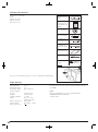
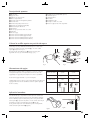
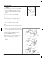

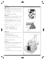


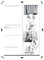
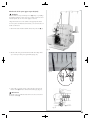

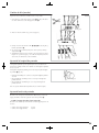


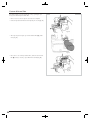


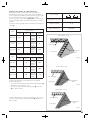

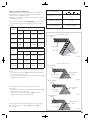
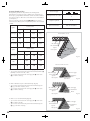

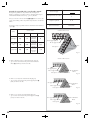

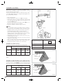
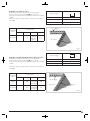


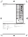
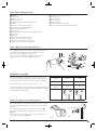
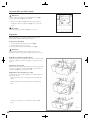
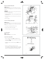


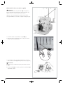


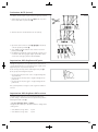

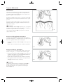
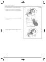

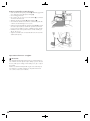
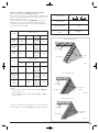
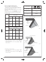


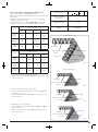
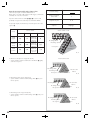
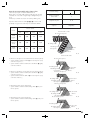
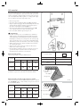


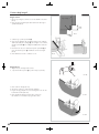
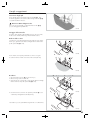
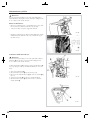


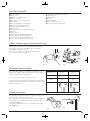


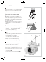
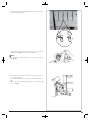


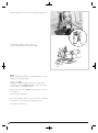
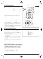

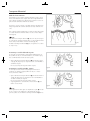
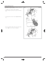
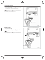

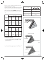
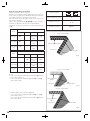

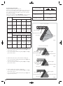


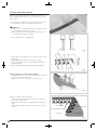
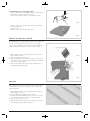


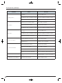

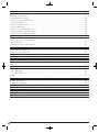


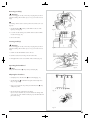
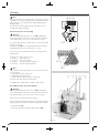

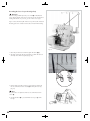
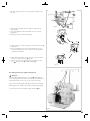
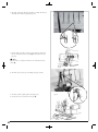


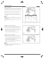


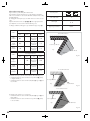
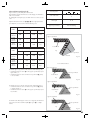

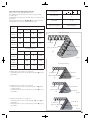
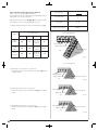
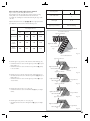
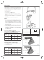


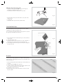
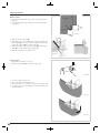


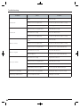


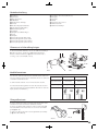
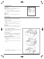
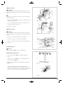


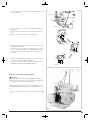
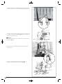

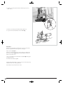
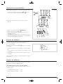

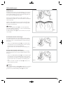


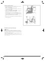

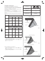

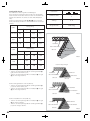
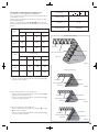

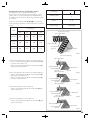


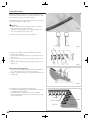
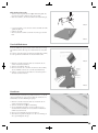
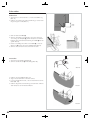
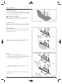
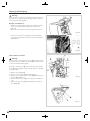
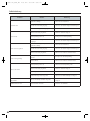


![[ES] Smart Energy Control Manual de Instrucciones y de Uso](http://vs1.manualzilla.com/store/data/006255326_1-bcb3ba9c27cbad56c6ef2fe6103a1f45-150x150.png)