1
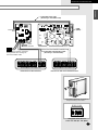
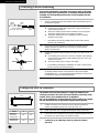
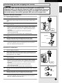
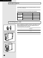
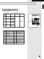
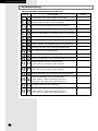
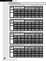
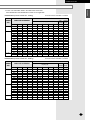
ENGLISH ESPAÑOL RUSSIAN E§§HNIKA åÌÓ„ÓÙÛÌ͈ËÓ̇θÌ˚È ÇÓÁ‰Û¯Ì˚È äÓ̉ˈËÓÌ ë‚Ó·Ó‰ÌÓ„Ó ëÓ‰ËÌÂÌËfl (éı·ʉÂÌËÂ Ë é·Ó„‚) DEUTSCH Free Joint Multi Air Conditioner (Cool and Heat) Acondicionador de aire libre del empalme multi (Refrigeración y Calefacción) Climatiseur Free Joint Multi (Refroidissement et Chauffage) Aria condizionata Free Joint Multi (Raffreddamento e Riscaldamento) Free Joint Multi ar condicionado (Refrigeração e Aquecimento) Free Joint Multi Klimaanlage (Kühlen und Wärmen) ¶ÔÏÏ·Ïfi ∫ÏÈÌ·ÙÈÛÙÈÎfi ªË¯¿ÓËÌ· ∂χıÂÚ˘ ŒÓˆÛ˘ (æ‡Í˘ - £¤ÚÌ·ÓÛ˘) PORTUGUÊS ITALIANO MH18VP2X MH19VP2X MH052FXEA2 MH068FXEA4 MH080FXEA4 FRANÇAIS INSTALLATION MANUAL MANUAL DE INSTALACIÓN MANUEL D’INSTALLATION MANUALE D’INSTALLZIONE MANUAL DE INSTALAÇÃO INSTALLATIONS-HANDBUCH E°XEIPI¢IO E°KATA™TA™H™ àçëíêìäñàü èé ìëíÄçéÇäÖ E S F I P D G R DB98-20237A(3) Safety Precautions The following safety precautions must be taken when using your air conditioner. WARNING INSTALLING THE UNIT Risk of electric shock. • Can cause injury or death. • Disconnect all remote electric power supplies before servicing, installing or cleaning. • This must be done by the manufacturer or its service agent or a similar qualified person in order to avoid a hazard. ◆ The unit should not be installed by the user. Ask the dealer or authorized company to install the units except room air conditioners for the U.S.A and Canada area. ◆ If the unit is installed improperly, water leakage, electric shock or fire may result. ◆ The air conditioner must be installed in accordance with national wiring regulations and safety regulations wherever applicable. ◆ Mount with the lowest moving parts at least 2.5 m above the floor or grade level. (If applicable) ◆ The manufacturer does not assume responsibility for accidents or injury caused by an incorrectly installed air conditioner. If you are unsure about installation, contact an installation specialist. ◆ When installing the built-in type air conditioner, keep all electrical cables such as the power cable and the connection cord in pipe, ducts, cable channels e.t.c to protect them against liquids, outside impacts and so on. POWER SUPPLY LINE, FUSE OR CIRCUIT BREAKER ◆ If the power cord of this air conditioner is damaged, it must be replaced by the manufacturer, its service agent or similarly qualified persons in order to avoid a hazard. ◆ The unit must be plugged into an independent circuit if applicable or connect the power cable to the auxiliary circuit breaker. An all pole disconnection from the power supply must be incorporated in the fixed wiring with a contact opening of >3mm. ◆ Do not use an extension cord with this product. ◆ If the unit is equipped with a power supply cord and a plug, the plug must be accessible after installation. ◆ This appliance must be installed accordance with the national wiring regulations. E-2 ENGLISH Contents ◆ PREPARING THE INSTALLATION ■ Deciding on Where to Install the Air Conditioner .......................................... ■ Air Conditioner and Accessories ................................................................... 4 8 ◆ INSTALLING THE INDOOR UNIT ■ Installing and Connecting the Outdoor Unit Drain Hose ............................... ■ Cutting/Extending the Piping ........................................................................ 8 9 ◆ INSTALLING THE OUTDOOR UNIT ■ Connecting the Cables to the Outdoor Unit .................................................. ■ Transmitter Installation (Optional) ................................................................. ■ Checking Correct Earthing ............................................................................ ■ Fixing the Unit in Position ............................................................................ 10 13 16 16 ◆ COMPLETING THE INSTALLATION ■ Connecting Up and Purging the Circuit......................................................... ■ Adding Refrigerant ........................................................................................ ■ Performing Leak Tests ................................................................................. ■ Pipe Installation with Indoor Units ................................................................. ■ Switch Setting and Testing Operation .......................................................... ■ Troubleshooting ............................................................................................ ■ Explaining Operations to the Owner ............................................................. 17 18 18 19 20 24 25 ◆ COMBINATION TABLE E-3 PREPARING THE INSTALLATION Deciding on Where to Install the Air Conditioner When deciding on the location of the air conditioner with the owner, the following restrictions must be taken into account. General Do NOT install the air conditioner in a location where it will come into contact with the following elements: ◆ Combustible gases ◆ Saline air ◆ Machine oil ◆ Sulphide gas ◆ Special environmental conditions If you must install the unit in such conditions, first consult your dealer. Outdoor Unit ◆ The outdoor unit must NEVER be placed on its side or upside down, as the compressor lubrication oil will run into the cooling circuit and seriously damage the unit. ◆ Choose a location that is dry and sunny, but not exposed to direct sunlight or strong winds. ◆ Do not block any passageways or thoroughfares. ◆ Choose a location where the noise of the air conditioner when running and the discharged air do not disturb any neighbours. ◆ Choose a position that enables the piping and cables to be easily connected to the indoor unit and the recommended length of 7.5 metres to be respected. (1 Unit) ◆ Install the outdoor unit on a flat, stable surface that can support its weight and does not generate any unnecessary noise and vibration. ◆ Position the outdoor unit so that the air flow is directed towards the outside, as indicated by the arrows on the top of the unit. ◆ Maintain sufficient clearance around the outdoor unit, as indicated in the diagram on the page opposite. ◆ If the outdoor unit is installed at a height, ensure that its base is firmly fixed in position; the maximum height is 7 metres. ◆ Make sure that the water dripping from the drain hose runs away correctly and safely. CAUTION ◆ You have just purchased a Free Joint Multi air conditioner and it has been installed by your installation specialist. ◆ This device must be installed according to the national electrical rules. ◆ Max input power & current is measured according to IEC standard and input power & current is measured according to ISO standard. E-4 ENGLISH PREPARING THE INSTALLATION ◆ MH18VP2X ◆ MH19VP2X Indoor unit Outdoor unit Power supply Ø, V, Hz MH18VP2-09 MH18VP2X 1,220-240~,50 Indoor unit Outdoor unit Power supply Ø, V, Hz MH19VP2X 1,220-240~,50 MH19VP2-07 MH19VP2-12 Respect the clearances and maximum lengths indicated in the diagram below when installing the unit. B-unit 200 mm or more A-unit 100 mm or more (h) 160 mm or more (H) 600 mm minimum A B 300 mm minimum 300 mm minimum 600 mm minimum Main power switch ◗ Piping length and the height Dimension Composition 1 Room max length 20 m A, B 2 Room total max Max height between length indoor unit & outdoor unit 40 m 15 m A+B (H) Max height between indoor units 3m (h) ◗ Piping outside diameter Unit Outer Diameter Liquid Gas MH18VP2-09 MH19VP2-07 1/4” 3/8” MH19VP2-12 E-5 PREPARING THE INSTALLATION Deciding on Where to Install the Air Conditioner (Continued) ◆ MH052FXEA2 ❊ The split type, 1-way cassette indoor units can be installed together. ◗ Piping outside diameter Outside diameter Liquid Gas Indoor unit Outdoor unit Power supply Ø, V, Hz Unit ✴✴20/26/35✴✴ MH052FXEA2 1, 220-240, 50 ✴✴20/26/35✴✴ 1/4” 3/8” 200 mm or more 100 mm or more 160 mm or more (h) 600 mm minimum 300 mm minimum 300 mm minimum A B 600 mm minimum Main power switch ◗ Piping length and the height Dimension Composition E-6 1 Room max length 20 m A, B 2 Room total max Max height between length indoor unit & outdoor unit 40 m 15 m A+B (H) Max height between indoor units 3m (h) (H) ENGLISH PREPARING THE INSTALLATION ◆ MH068FXEA4 / MH080FXEA4 ❊ The split type, 1-way cassette, duct type indoor units can be installed together. ◗ Piping outside diameter Indoor unit Outdoor unit Power supply Ø, V, Hz ✴✴23/26/35/52✴✴ MH068FXEA4 MH080FXEA4 1, 220-240, 50 Outside diameter Liquid Gas 1/4” 3/8” 1/4” 1/2” Unit ✴✴23/26/35✴✴ ✴✴52✴✴ 200 mm or more 100 mm or more 160 mm or more (h) (H) 600 mm minimum 300 mm minimum 300 mm minimum A B C D 600 mm minimum Main power switch ◗ Piping length and the height Dimension Composition 1 Room max length 25 m A, B, C, D 2 Room total max 3 Room total max 4 Room total max Max height between length length length indoor unit & outdoor unit 30 m 45 m 70 m 15 m A+B A+B+C A+B+C+D (H) Max height between indoor units 3m (h) E-7 PREPARING THE INSTALLATION Air Conditioner and Accessories The following accessories are supplied with the air conditioner. Accessories in the Outdoor Unit Case ◆ MH18VP2X / MH19VP2X / MH052FXEA2 3-wire Power Cable (option) Drain Plug 2-wire Assembly Cable (option) Rubber Leg Flare Nuts, 6.35mm outer pipe diameter Transmitter power cable Flare Nuts, 9.52mm outer pipe diameter Energy Label Installation Manual TIONS OWNER'S INSTRUC CIONES MANUAL DE INSTRUC L'USO ISTRUZIONI PER ÕES MANUAL DE INSTRUÇ TION MANUEL D'UTILISA EISUNG GEBRAUCHSANW EISUNG GEBRAUCHSANW EISUNG GEBRAUCHSANW Air ConditionerSplit Splut-type Room doméstico sistema ad unità Separate Aire acondicionado d'aria per ambienti Condizionatorede ar condicionado tipo Split Aparelho type séparé Climatiseur de Geteilte raumklimaanlage Geteilte raumklimaanlage ❋ Attach Energy Label to the outdoor unit properly when installing. ◆ MH068FXEA4 / MH080FXEA4 3-wire Power Cable (option) Drain Plug 2-wire Assembly Cable (option) Transmitter power cable Installation Manual TIONS OWNER'S INSTRUC CIONES MANUAL DE INSTRUC L'USO ISTRUZIONI PER ÕES MANUAL DE INSTRUÇ TION MANUEL D'UTILISA EISUNG GEBRAUCHSANW EISUNG GEBRAUCHSANW EISUNG GEBRAUCHSANW Air ConditionerSplit Splut-type Room doméstico sistema ad unità Separate Aire acondicionado d'aria per ambienti Condizionatorede ar condicionado tipo Split Aparelho type séparé Climatiseur de Geteilte raumklimaanlage Geteilte raumklimaanlage Rubber Leg Flare Nuts, 6.35mm outer pipe diameter Flare Nuts, 9.52mm outer pipe diameter Flare Bolt (Nut 1/2”, Bolt 3/8” ) Energy Label ❋ Attach Energy Label to the outdoor unit properly when installing. ➢ The 3-wire power cable and the 2-wire assembly cable are optional. If these cables are not supplied, use the standard cable approved by IEC standard. The specification for cables : Use AWG Cross sectional area (mm2) 3-wire power cable for main power supply 13 or fewer 2.5 or more 3-wire power cable for indoor power supply 16 or fewer 1.5 or more 2-wire assembly cable for communication 16 or fewer 1.5 or more Installing and Connecting the Outdoor Unit Drain Hose Drain hole E-8 When using the air conditioner in the heating mode, ice may accumulate. During de-icing, the condensed water must be drained off safely. Consequently, you must install a drain hose on the outdoor unit, following the instructions below. 1 Insert the drain plug into the drain hole on the underside of the outdoor unit. 2 Connect the drain hose to the drain plug. 3 Ensure that the drained water runs off correctly and safely. INSTALLING THE INDOOR UNIT ENGLISH Cutting/Extending the Piping 1 Make sure that you have the required tools available (pipe cutter, reamer, flaring tool and pipe holder). 2 If you wish to shorten the piping, cut it using a pipe cutter, taking care to ensure that the cut edge remains at a 90° angle with the side of the pipe, and referring to the illustrations below for examples of edges cut correctly and incorrectly. Oblique O 90 O Rough x Burr x x 3 To prevent any gas from leaking out, remove all burrs at the cut end of the pipe, using a reamer. 4 Slide a flare nut on to the pipe and modify the flare. Outer Diameter(D) 6.35 mm 9.52 mm 12.70 mm 5 Check that the flaring is correct, referring to the illustrations below for examples of incorrect flaring. x x Inclined 6 Damaged Surface x x Cracked Uneven Thickness Align the pipes to be connected and tighten the flare nuts first manually and then with a torque wrench, applying the following torque. Outer Diameter 6.35 mm 9.52 mm 12.70 mm 7 Depth(A) 1.3 mm 1.8 mm 2.0 mm Torque(kgf•cm) 140~170 250~280 380~420 For further details on how to connect up to the outdoor unit and purge the circuit, refer to page 17. E-9 INSTALLING THE OUTDOOR UNIT Connecting the Cables to the Outdoor Unit 2 electric cables must be connected to the outdoor unit: ◆ The assembly cable connecting the indoor unit to the outdoor unit. ◆ The power cable connecting the auxiliary circuit breaker to the outdoor unit. 1 Remove the terminal board cover on the side of the outdoor unit. 2 Connect the assembly cable with the power cable such as figure. ➢ ➢ 3 Each wire is labelled with the corresponding terminal number. Ensure the wire number of the indoor unit and the terminal number of the outdoor unit. Connect the earth wires to the earth terminals. ➢ Refer to the page 16 for further details on how to check that earthing is correct. 4 Fix the cables with cable clamps near terminal blocks to protect the wire connection to the terminals from force on the wire. 5 Replace the terminal board cover, carefully tightening the screw. 6 Connect the power cable to the auxiliary circuit breaker. ❊ The designs and shape are subject to change according to the model. ◆ MH18VP2X / MH19VP2X / MH052FXEA2 A-unit 1(L) 2(N) B-unit Indoor unit F1 F2 1(L) 2(N) F1 F2 Assembly cable 1 2 E 1 F1 F2 2 E Earth terminal 1 2 F1 F2 Earth terminal B C B E F1 F2 1 Earth terminal C 2 E F1 F2 Earth terminal Outdoor unit 1(L) 2(N) 1(L) 2(N) A L N 1 2 B Power cable to indoor units A Cable Type: A B Cable Type: B A F1 F2 F1 F2 Main Power supply cable A B E Earth terminal Communication cable to indoor units C Cable Type: C The specification for cables : Type E-10 AWG Cross sectional area (mm2) A Main Power Supply 3-wire power cable 13 or fewer 2.5 or more B Indoor Power Supply 3-wire power cable 16 or fewer 1.5 or more C 2-wire assembly cable 16 or fewer 1.5 or more Use ENGLISH INSTALLING THE OUTDOOR UNIT ◆ MH068FXEA4 / MH080FXEA4 A-unit 1(L) 2(N) B-unit F1 F2 2 E 1 1(L) 2(N) F1 F2 1 1 2 E F2 1(L) 2(N) F1 F2 Assembly cable 1 F1 F2 1 Earth terminal 2 D-unit F1 F2 2 E Earth terminal C B F1 2 E Earth terminal C-unit Indoor unit 1(L) 2(N) F1 F2 1 2 E Earth terminal B C B E F1 F2 1 Earth terminal F2 F1 F2 Earth terminal C E 2 F1 F1 F2 1 Earth terminal 2 B C E F1 F2 Earth terminal Outdoor unit 1(L) 2(N) 1(L) 2(N) 1(L) 2(N) 1(L) 2(N) A B C L N Main Power supply cable 1 2 E D Power cable to indoor units Earth terminal A Cable Type: A B Cable Type: B A F1 F2 F1 F2 A B C D Communication cable to indoor units C Cable Type: C The specification for cables : Type Use AWG Cross sectional area (mm2) A Main Power Supply 3-wire power cable 13 or fewer 2.5 or more B Indoor Power Supply 3-wire power cable 16 or fewer 1.5 or more C 2-wire assembly cable 16 or fewer 1.5 or more E-11 INSTALLING THE OUTDOOR UNIT Connecting the Cables to the Outdoor Unit (Continued) Preparation of cables for outdoor unit terminal block 1 2 E ◗ Main power supply cable : L(mm) L (mm) Cable of indoor unit 1 2 E Main Power 20 20 90 ◗ Power cable to indoor units : L(mm) Cable of indoor unit 1 2 E A 60 60 80 B 60 60 80 C 70 70 110 ✴✴068 / 080✴✴ D 90 90 90 ✴✴068 / 080✴✴ Remark For only For only ◗ Communication cable to indoor units : L(mm) ❊ The designs and shape are subject to change according to the model. Cable of indoor unit 1 2 15 15 Remark A B E-12 For C ✴✴068 / 080✴✴ D ✴✴068 / 080✴✴ only For only INSTALLING THE OUTDOOR UNIT ENGLISH Transmitter Installation (Optional) ◆ MH18VP2X / MH19VP2X / MH052FXEA2 Accessories (Transmitter) Transmitter Transmitter power cable Transmitter communication cable Installation Manual Case Cable-tie TIONS OWNER'S INSTRUC CIONES MANUAL DE INSTRUC L'USO ISTRUZIONI PER ÕES MANUAL DE INSTRUÇ TION MANUEL D'UTILISA EISUNG GEBRAUCHSANW EISUNG GEBRAUCHSANW EISUNG GEBRAUCHSANW Air ConditionerSplit Splut-type Room doméstico sistema ad unità Separate Aire acondicionado d'aria per ambienti Condizionatorede ar condicionado tipo Split Aparelho type séparé Climatiseur de Geteilte raumklimaanlage Geteilte raumklimaanlage Accessories (Outdoor Unit) 3-wire Power Cable (option) 2-wire Assembly Cable (option) Drain Plug Transmitter power cable Rubber Leg Flare Nuts, 6.35mm outer pipe diameter Flare Nuts, 9.52mm outer pipe diameter Energy Label 1 Fix the case at 3 hinges on the side of the control box in the outdoor unit. (See the picture) 2 Attach the transmitter PCB to the case in the control box in the outdoor unit, then connect the power and the communication cable between the transmitter and the outdoor unit; refer to the figure of page 15. 3 If you install a transmitter to an outdoor unit, every indoor unit which is connected to an outdoor unit can be controlled simultaneously. 4 Each outdoor unit connected to the same centralized controller has its own transmitter. 7seg. LED Display side Fix the case with hinges (Control Box in the outdoor unit) E-13 INSTALLING THE OUTDOOR UNIT Transmitter Installation (Optional) (Continued) ◆ MH068FXEA4 / MH080FXEA4 Accessories (Transmitter) Transmitter Transmitter communication cable Transmitter power cable Installation Manual Case Cable-tie TIONS OWNER'S INSTRUC CIONES MANUAL DE INSTRUC L'USO ISTRUZIONI PER ÕES MANUAL DE INSTRUÇ TION MANUEL D'UTILISA EISUNG GEBRAUCHSANW EISUNG GEBRAUCHSANW EISUNG GEBRAUCHSANW Air ConditionerSplit Splut-type Room doméstico sistema ad unità Separate Aire acondicionado d'aria per ambienti Condizionatorede ar condicionado tipo Split Aparelho type séparé Climatiseur de Geteilte raumklimaanlage Geteilte raumklimaanlage Accessories (Outdoor Unit) 3-wire Power Cable (option) 2-wire Assembly Cable (option) Drain Plug Energy Label Rubber Leg Flare Nuts, 6.35mm outer pipe diameter Flare Nuts, 9.52mm outer pipe diameter Flare Bolt (Nut 1/2”, Bolt 3/8” ) 7seg. LED Display side Transmitter 1 Fix the case with bolts on the control box in the outdoor unit. (See the picture) Terminal side 2 Attach the transmitter PCB to the case in the control box in the outdoor unit, then connect the power and the communication cable between the transmitter and the outdoor unit; refer to the figure of page 15. 3 If you install a transmitter to an outdoor unit, every indoor unit which is connected to an outdoor unit can be controlled simultaneously. 4 Each outdoor unit connected to the same centralized controller has its own transmitter. Bolts spec. M4 Fix the case with bolts (Control Box in the outdoor unit) E-14 Transmitter power cable ENGLISH INSTALLING THE OUTDOOR UNIT Transmitter power cable (Accessory in the outdoor unit) Transmitter PCB CN59 (White) CN03 (Blue) Center Controller One housing is used for connection although there are 2 housings on the communication cable. Outdoor unit PCB Transmitter communication cable (Accessory in the transmitter) Terminal Block in the outdoor unit Terminal Block in the outdoor unit MH068FXEA4/MH080FXEA4 MH18VP2X/MH19VP2X/MH052FXEA2 ❊ The designs and shape are subject to change according to the model. K1 K2 K3 K4 Change DIP switch-K2 in all indoor units PCB (K2 : ON → OFF) E-15 INSTALLING THE OUTDOOR UNIT Checking Correct Earthing If the power distribution circuit does not have an earth or the earth does not comply with specifications, an earthing electrode must be installed. The corresponding accessories are not supplied with the air conditioner. Carbon plastic Steel core PVC-insulated green/ yellow wire, 2mm2 x 3.5 m To earthing screw 1 Select an earthing electrode that complies with the specifications given in the illustration opposite. 2 Determine a suitable location for the earthing electrode: ◆ In damp hard soil rather than loose sandy or gravel soil that has a higher earthing resistance ◆ Away from underground structures or facilities, such as gas pipes, water pipes, telephone lines and underground cables ◆ At least two meters away from a lightening conductor earthing electrode and its cable ➢ 3 Dig a hole of the size indicated in the illustration opposite, drive the earthing electrode into position and cover the top of the electrode with the excavated soil. 4 Install a green/yellow insulated earthing wire (Ø1.6 mm, section 2 mm2 or greater): ◆ If the earthing wire is too short, connect an extension lead, soldering the connection and wrapping it with insulating tape (do not bury the soldered connection) ◆ Secure the earthing wire in position with staples 30 cm 50 cm The earthing wire for the telephone line cannot be used to earth the air conditioner. ➢ If the earthing electrode is installed in an area of heavy traffic, its wire must be connected securely. 5 Carefully check the installation, by measuring the earthing resistance with an earthing resistance tester. If the resistance is above the required level(Example:100Ω), drive the earthing electrode deeper into the ground or increase the number of earthing electrodes. 6 Connect the earthing wire to the earthing screw on the air conditioner. Fixing the Unit in Position The outdoor unit must be installed on a rigid and stable base to avoid any increase in the noise level and vibration, particularly if the outdoor unit is to be installed close to a neighbour. ‘X’ mm ‘Y’ mm If it is to be installed in a location exposed to strong winds or at a height, the unit must be fixed to an appropriate support (wall or ground). Rubber leg Model X Y MH18VP2X MH19VP2X MH052FXEA2 660 330 MH068FXEA4 MH080FXEA4 660 350 E-16 1 Position the outdoor unit so that the air flow is directed towards the outside, as indicated by the arrows on the top of the unit. 2 Attach the outdoor unit to the appropriate support using anchor bolts. 3 If the outdoor unit is exposed to strong winds, install shield plates around the outdoor unit, so that the fan can operate correctly. ➢ Certainly fix up its rubber leg in order to prevent its vibration and noise. COMPLETING THE INSTALLATION Connecting Up and Purging the Circuit ENGLISH CAUTION The air in the indoor unit and in the pipe must be purged. If air remains in the refrigeration pipes, it will affect the compressor, reduce to cooling/heating capacity and could lead to a malfuction. Refrigerant for air purging is not charged in the outdoor unit. Use Vacuum Pump as shown at the right figure. Each unit must be purged in turn. ◆ MH18VP2X / MH19VP2X / MH052FXEA2 1 Check the piping connections. 2 Connect the charging hose of low pressure side of manifold gauge to the packed valve having a service port (3/8” service valve) as shown at the figure. 3 Open the valve of the low pressure side of manifold gauge counter-clockwise. 4 Purge the air from the system using vacuum pump for about 10 minutes. - Close the valve of the low pressure side of manifold gauge clockwise. - Make sure that pressure gauge show -0.1MPa(-76cmHg) after about 10 minutes. This procedure is very important in order to avoid gas leak. - Turn off the vacuum pump - Remove the hose of the low pressure side of manifold gauge. 5 Set valve cork of both liquid side and gas side of packed valve to the open position. 6 Mount the valve stem nuts and the service port cap to the valve, and tighten them at the torque of 183kgf•cm with a torque wrench. 7 Check for gas leakage. - At this time, especially check for gas leakage from the 3-way valve’s stem nuts, and from the service port cap. Indoor A-unit Indoor B-unit Vacuum Pump Valve stem Stem cap Service port ◆ MH068FXEA4 / MH080FXEA4 1 Check the piping connections. 2 Connect the charging hose of low pressure side of manifold gauge to the packed valve having a service port (5/8” Packed valve) as shown at the figure (Value stem: 1/2” - 20UNF). 3 Open the valve of the low pressure side of manifold gauge counter clockwise. 4 Purge the air from the system using vacuum pump for about 30 minutes. - Close the valve of the low pressure side of manifold gauge clockwise. - Make sure that pressure gauge show -0.1MPa(-76cmHg) after about 30 minutes. This procedure is very important in order to avoid gas leak. - Turn off the vacuum pump. - Remove the hose of the low pressure side of manifold gauge. 5 Set valve cork of both liquid side and gas side of packed valve to the open position. 6 Mount the valve stem nuts and the service port cap to the valve, and tighten them at the torque of 183kgf•cm with a torque wrench. 7 Check for gas leakage. - At this time, especially check for gas leakage from the 3-way valve’s stem nuts, and from the service port cap. A B C D Vacuum Pump Valve stem Stem cap Service port E-17 COMPLETING THE INSTALLATION Adding Refrigerant If you install the excessive length of pipe, add additional refrigerant as 15g per unit meter ; refer to the table below. Refer to the Service Manual for more details on this operation. Model Total connecting pipe length(L) Adding refrigerant MH18VP2X MH19VP2X MH052FXEA2 LT ≤ 20 m Chargeless LT > 20 m (LT - 20 m) x15g LT ≤ 40 m Chargeless LT > 40 m (LT - 40 m) x15g MH068FXEA4 MH080FXEA4 Performing Leak Tests C D Before completing the installation (insulation of the cables, hose and piping and fixing of the indoor unit to the installation plate), you must check that there are no gas leaks. To check for gas leaks on the... Then, using a leak detector, check the... Indoor unit Flare nuts at the end of sections C and D. Outdoor unit Valves on sections A and B. MH18VP2X / MH19VP2X / MH052FXEA2 A MH068FXEA4 / MH080FXEA4 A B E-18 COMPLETING THE INSTALLATION ENGLISH Pipe Installation with Indoor Units ◆ MH068FXEA4 / MH080FXEA4 Follow different orders depending on the capacity of indoor units. MH026/035F✴EA OUTDOOR UNIT Install pipes between indoor and outdoor units orderly as [A → B → C → D]. ◆ MH052F✴EA Install pipes between indoor and outdoor units orderly as [D → C]. ◆ A unit B unit Examples ◆ 2Rooms : MH035FPEA + MH052FPEA A MH035FPEA A B B C C D MH052FPEA B MH052FPEA D unit MH035FPEA D (o) A C unit (x) MH035FPEA MH052FPEA C D ❊ The pinch pipe is installed initially on the part A. (x) ◆ 3Rooms : MH026FPEA + MH035FPEA + MH052FPEA A B MH026FPEA MH035FPEA C D A B C MH052FPEA (o) MH052FPEA MH035FPEA MH026FPEA Flare nut D (x) ❊ If the pinch pipe is not installed, please screw the part A using the flare nut of the part B, C, or D. E-19 COMPLETING THE INSTALLATION Switch Setting and Testing Operation ◆ MH18VP2X / MH19VP2X / MH052FXEA2 To complete the installation, perform the following checks and tests to ensure that the air conditioner is operating correctly. Step 1 Review all the following elements in the installation: OUTDOOR UNIT A unit ◆ Installation site strength ◆ Piping connection tightness to detect any gas leakage ◆ Connection wiring ◆ Heat-resistant insulation of the piping ◆ Drainage ◆ Earthing wire connection Step 2 Check the room select switch in the indoor unit and in the outdoor unit. Set the switch properly as below. (For example: 2 Rooms) B unit Indoor unit A unit B unit Manual Addressing (For example: 2 Rooms) SW02 SW02 Auto Addressing (For example: 2 Rooms) SW02 SW02 Outdoor unit SW 01 SW 02 Manual Addressing (For example: 2 Rooms) Auto Addressing (For example: 2 Rooms) ◆ ◆ ◆ The liquid and gas refrigerant pipes should not be crossed with each other. The switch for the indoor unit address setting is in each indoor unit PCB. The manual addressing number of the indoor unit must be set as above. (A unit ➝ 0, B unit ➝ 1) Step 3 Automated checking of pipe connection (Auto addressing option) ◆ Apply the power to the outdoor unit. ◆ Push the [K2] button 4 times in the outdoor PCB display. Button [K2] 4 times DIS 01 DIS 02 Display SW02 [DIS 01] is flickering on the setting time. SW01 Outdoor Temperature Time duration (OFF) DIS01 K1 DIS02 K2 K3 K4 Outdoor PCB Display E-20 15°C or more Less than 15°C (Cool mode) (Heat mode) 3 min ~ 5 min 20 min ~ 30 min ◆ ◆ ◆ It could take more time depending on the indoor and outdoor temperature. If the checking is finished, outdoor unit stops automatically. [DIS 02] shows the indoor unit under searching. ◆ Function of Step 3 Mode Function Auto Addressing Checking the connection & addressing Manual Addressing Checking the connection only ENGLISH COMPLETING THE INSTALLATION ◆ MH068FXEA4 / MH080FXEA4 To complete the installation, perform the following checks and tests to ensure that the air conditioner is operating correctly. Step 1 Review all the following elements in the installation: OUTDOOR UNIT ◆ Installation site strength ◆ Piping connection tightness to detect any gas leakage ◆ Connection wiring ◆ Heat-resistant insulation of the piping ◆ Drainage ◆ Earthing wire connection A unit B unit Step 2 Check the room select switch in the indoor unit and in the outdoor unit. Set the switch properly as below. (For example : 4Rooms) Indoor unit A unit B unit C unit D unit C unit Manual Addressing (For example: 4 Rooms) SW02 SW02 SW02 SW02 D unit Auto Addressing (For example: 4 Rooms) SW02 SW02 SW02 SW02 Outdoor unit SW 01 SW 02 Manual Addressing (For example: 4 Rooms) Auto Addressing (For example: 4 Rooms) ◆ ◆ ◆ The liquid and gas refrigerant pipes should not be crossed with each other. The switch for the indoor unit address setting is in each indoor unit PCB. The manual addressing number of the indoor unit must be set as above. (A unit ➝ 0, B unit ➝ 1, C unit ➝ 2, D unit ➝ 3) Step 3 Automated checking of pipe connection (Auto addressing option) ◆ Apply the power to the outdoor unit. ◆ Push the [K2] button 4 times in the outdoor PCB display. Button [K2] 4 times DIS 01 DIS 02 Display [DIS 01] is flickering on the setting time. SW02 SW01 Outdoor Temperature Time duration 15°C or more Less than 15°C (Cool mode) (Heat mode) 5 min ~ 10 min 20 min ~ 50 min ◆ ◆ ◆ It could take more time depending on the indoor and outdoor temperature. If the checking is finished, outdoor unit stops automatically. [DIS 02] shows the indoor unit under searching. ◆ Function of Step 3 Mode Function Auto Addressing Checking the connection & addressing Manual Addressing Checking the connection only (OFF) DIS01 K1 DIS02 K2 K3 K4 Outdoor PCB Display E-21 COMPLETING THE INSTALLATION Switch Setting and Testing Operation (Continued) Step 4 Testing operation (Indoor unit) Press the Result: button. ◆ The indicator lights on the indoor unit flash at half-second intervals. ◆ While the indoor unit opens, the indoor unit fan runs to start. Press the Result: button. The outdoor unit operates in cooling or heating mode as following the room temperature. Air flow direction ➢ Press the button and check that the air flow blades work properly. It could take maximum 60 minutes to operate for the protection of the compressor if the outdoor temperature is below -5°C. Ampere Limit Setting & Changing Procedure ❊ The designs and shape are subject to change according to the model. WARNING ◆ Do not adjust the "Ampere Limit Switch", because it needs to meet HDB requirement or Local authorities. ◆ "Ampere Limit Switch" is initially set to the default value (table below). ◆ "Ampere Limit Switch" is on the PCB of outdoor unit. ◆ Contact the authorized service technician or dealer for setting and changing the "Ampere Limit Switch". ◆ Before changing the "Ampere Limit Switch", turn off the main power of the system. ◆ Please refer to the lower figure and table. Ampere SW02 Switch SW01 MH18VP2X MH19VP2X MH052FXEA2 MH068FXEA4 MH080FXEA4 13.0A (Default) 17.0A (Default) 12.0A 14.0A Switch Selection Switch 3 4 ON ON ON OFF OFF ON OFF OFF (OFF) DIS01 DIS02 Indoor unit address K1 K2 K3 K4 (OFF) (OFF) View data display 10.0A 11.0A Outdoor PCB Display (OFF) 8.0A 10.0A (OFF) E-22 ENGLISH COMPLETING THE INSTALLATION Settings of PCB Display of the Outdoor unit ◆ Key Options of PCB Display - K1 : Test button - K3 : Reset button Key - K2 : Function button - K4 : View mode change button K1 K2 K3 1 Heat mode Try-run (Display: ) Refrigerant Charging (Display: ) 2 - Cool mode Try-run (Display: ) K4 Push 3 - Pump down (Display: ) - Checking of pipe connection (Display: ) SW02 Switch (OFF) DIS01 Reset View mode change DIS02 Indoor unit address K1 4 SW01 K2 K3 K4 View data display Outdoor PCB Display ◆ K4 View mode Display changes Push Display Explanation Push Display Explanation 8 Discharge temperature 9 OLP temperature 10 Condenser temperature EEV0 current step 11 Outdoor temperature 4 EEV1 current step 12 First current 5 EEV2 current step 13 6 EEV3 current step 14 Target Discharge temperature Total capacity of the indoor units 7 Fan RPM (H: high, L: low, Blank: off) 15 Safety control 2 Present Compressor Frequency Target Compressor Frequency Order Compressor Frequency 3 0 1 E-23 COMPLETING THE INSTALLATION Troubleshooting The error indicated on the PCB display of outdoor unit DISPLAY EXPLANATION Communication error (indoor unable to receive data) Outdoor unit communication error (Abnormal data from indoor unit over 60 packet) Indoor unit room temperature sensor error (Open/Short) Indoor unit heat exchanger in temperature sensor error (Open/Short) Indoor unit heat exchanger out temperature sensor error (Open/Short) Indoor unit sensor error-Evaporator pipe in sensor Indoor unit sensor error-Evaporator pipe out sensor Indoor unit sensor error-Evaporator pipe in and out sensor all More than two indoor units cool and heat simultaneously The number of Indoor unit mismatched Communication error between the outdoor and indoor unit Outdoor communication error between main PCB and sub PCB Outside temperature sensor error (Short/Open) - Error level: over 4.9V(-50°C) under 0.4V(93°C) Condenser temperature sensor error(Short/Open) - Error level: over 4.9V(-50°C) under 0.4V(93°C) Outdoor unit sensor error - Condenser out sensor (Short/Open) Compressor discharge sensor error (Short/Open) - Error condition : outdoor temperature under -10°C - Error level : over 4.95V(-30°C) under 0.5V(151°C) Compressor discharge sensor detached Compressor OLP sensor error (Short/Open) - Error condition : outdoor temperature under -20°C - Error level : over 4.95V(-30°C) under 0.5V(151°C) E-24 REMARK COMPLETING THE INSTALLATION Troubleshooting (Continued) DISPLAY EXPLANATION Outdoor unit freezing (Compressor stop) ENGLISH The error indicated on the PCB display of outdoor unit REMARK ✴ Outdoor unit overload - Safety control(Compressor stop) Outdoor unit high discharge temperature - Safety control (Compressor stop) ✴ Outdoor unit EEV open - Self diagnosis Outdoor unit EEV close - Self diagnosis High temperature (over 30°C) of outdoor as heating mode Low temperature (under -5°C) of indoor as cooling mode Communication cable mismatched between indoor and outdoor unit Inverter compressor starting failure (5 times) Compressor trip by input current control mode Compressor trip by OLP temperature control mode DC peak error Full ampere compressor trip (Over 30A) DC link error (under 150V, over 410V) Abnormal compressor running Current sensor error DC link sensor error Compressor trip (over input current 24A, under minimum running frequency) EEPROM read / write failure Inverter micom zero-crossing error Leak on outdoor unit under self diagnosis Remark ✴: Check the pipe connections with the address of the indoor units. Explaining Operations to the Owner Before leaving the premises on which you have installed the air conditioner, you should explain the following operations to the owner, making reference to the appropriate pages in the owner’s instruction booklet. 1 How to start and stop the air conditioner. 2 How to select the operating mode and adjust the temperature and fan settings. 3 How to adjust the air flow direction. 4 How to set the timers. 5 How to remove and clean the filters. ➢ Once the owner is happy with the basic operations, hand over the owner’s instruction booklet and this installation manual for storage in a handy and safe place. E-25 COMBINATION TABLE Combination Table MH052FXEA2 (Current Limited 10A - Cooling) Conversion formula: kW=Btu/h x 0.000293 Current Limited 10A Outdoor unit Indoor unit combination A 1 Unit 2 Unit B 2000 2600 3500 2000 2000 2600 ✽1) 2000 ✽2) 2600 3500 2000 2600 2600 ✽1) 3500 ✽2) 3500 3500 Total 2000 2600 3500 4000 4600 5200 ✽1) 5500 ✽2) 6100 7000 Capacity (W) B A 2000 2600 3500 2000 2000 2600 ✽1) 2500 ✽2) 2800 3250 - MH18VP2X model is applicable for ✽1) in the table above. Outdoor unit 2 Unit 2200 2900 3800 2200 2200 2900 2200 2900 3800 B ✽1) ✽2) 2200 2900 2900 ✽1) 3800 ✽2) 3800 3800 Total 2200 2900 3800 4400 5100 5800 ✽1) 6000 ✽2) 6700 7600 A Total Operating Current (W) (A) 2200 2900 2900 ✽1) 3500 ✽2) 3670 3650 2200 2900 3800 4400 5100 5800 ✽1) 6000 ✽2) 6570 7300 MH19VP2X model is applicable for 850 1150 1560 1600 1760 1805 ✽1) 1850 ✽2) 2190 2190 ✽2) A Power Consumption Operating Current (W) (A) Total B MH052FXEA2 (Full Load Ampere - Heating) B Total ✽2) 3.6 3.8 4.7 6.2 6.4 6.7 ✽1) 7.1 ✽2) 8.7 9.5 in the table above. Full Load Ampere Capacity (W) A B Total 2200 2200 2200 2200 2900 2900 2900 2900 3800 3800 3800 3800 4400 2 Unit 2200 2200 4400 2200 2200 5100 2900 2900 5100 2200 2200 5800 ✽1) 2900 ✽1) 2900 ✽1) 5800 ✽1) 2900✽1) 2900 ✽1) 6000 ✽2) 3800 ✽2) 3500 ✽2) 6000 ✽2) 2500✽2) 2200 ✽2) 6570 3800 3670 6700 2900 2900 7300 3800 3650 7600 3650 3800 - MH18VP2X model is applicable for ✽1) in the table above. MH19VP2X model is applicable for E-26 770 800 1000 1350 1410 1500 ✽1) 1600 ✽2) 1950 2160 Conversion formula: kW=Btu/h x 0.000293 Indoor unit combination A in the table above. Full Load Ampere Capacity (W) 2000 2000 2000 2000 2600 2600 2600 2600 3500 3500 3500 3500 4000 2 Unit 2000 2000 4000 2000 2000 4600 2600 2600 4600 2000 2000 5200 ✽1) 2600 ✽1) 2600 ✽1) 5200 ✽1) 2600✽1) 2600 ✽1) 5500 ✽2) 3500 ✽2) 3000 ✽2) 5500 ✽2) 2500✽2) 2000 ✽2) 5900 3500 3100 6100 2800 2600 6500 3500 3250 7000 3250 3500 - MH18VP2X model is applicable for ✽1) in the table above. MH19VP2X model is applicable for 1 Unit 3.9 5.3 7.0 7.1 7.8 8.2 ✽1) 8.5 ✽2) 9.7 9.7 Conversion formula: kW=Btu/h x 0.000293 1 Unit Outdoor unit in the table above. Power Consumption Total B 2200 2900 3800 2200 2200 2900 ✽1) 2500 ✽2) 2900 3650 Indoor unit combination B ✽2) 3.6 3.8 4.7 6.2 6.4 6.7 ✽1) 7.1 ✽2) 8.7 9.5 Current Limited 10A Capacity (W) MH052FXEA2 (Full Load Ampere - Cooling) A (A) 770 800 1000 1350 1410 1500 ✽1) 1600 ✽2) 1950 2160 Conversion formula: kW=Btu/h x 0.000293 - MH18VP2X model is applicable for ✽1) in the table above. Outdoor unit (W) 2000 2600 3500 4000 4600 5200 ✽1) 5500 ✽2) 5900 6500 MH19VP2X model is applicable for Indoor unit combination A 1 Unit Operating Current Total 2000 2600 2600 ✽1) 3000 ✽2) 3100 3250 MH052FXEA2 (Current Limited 10A - Heating) Power Consumption Power Consumption Operating Current (W) (A) 850 3.9 1150 5.3 1560 7.0 1600 7.1 1760 7.8 1805 ✽1) 8.2 ✽1) 1850 ✽2) 8.5 ✽2) 2190 9.7 2420 10.7 ✽2) in the table above. COMBINATION TABLE MH068FXEA4 (Current Limited 10A - Cooling) ENGLISH ✴ Indoor unit combination 2600 in the table below means that both MH023FPEA and MH026FPEA models can be applicable. Conversion formula: kW=Btu/h x 0.000293 Current Limited 10A Indoor unit combination Outdoor unit A 1 Unit 2 Unit 3 Unit 4 Unit B 2600 3500 5200 2600 2600 2600 3500 3500 5200 2600 2600 2600 2600 2600 3500 3500 2600 2600 2600 3500 5200 3500 5200 5200 2600 2600 2600 3500 3500 3500 3500 2600 2600 C 2600 3500 5200 3500 5200 3500 5200 2600 2600 Power Operating Consumption Current Capacity (W) D A 2600 3500 2600 3500 5200 2600 2600 2489 3412 2962 3761 2508 2248 1881 2037 1757 2512 2222 1881 1757 B 2600 3500 4978 3412 4401 3761 2508 2248 1881 2742 2365 2512 2222 1881 1757 MH068FXEA4 (Current Limited 10A - Heating) C 2508 3027 3761 2742 3513 2512 3301 1881 1757 D Total (W) 1881 2365 2600 3500 5200 5200 6100 7467 6824 7363 7522 7524 7523 7522 7522 7635 7535 7745 7522 7635 830 1115 1550 1408 1645 2140 1910 2154 2157 2147 2150 2147 2151 2144 2152 2141 2137 2134 (A) 3.9 5.2 7.0 6.3 7.4 9.4 8.5 9.5 9.4 9.5 9.5 9.3 9.4 9.3 9.4 9.3 9.3 9.3 Conversion formula: kW=Btu/h x 0.000293 Current Limited 10A Indoor unit combination Outdoor unit A 1 Unit 2 Unit 3 Unit 4 Unit 2900 3800 5600 2900 2900 2900 3800 3800 5600 2900 2900 2900 2900 2900 3800 3800 2900 2900 B 2900 3800 5600 3800 5600 5600 2900 2900 2900 3800 3800 3800 3800 2900 2900 C 2900 3800 5600 3800 5600 3800 5600 2900 2900 Power Operating Consumption Current Capacity (W) D A 2900 3800 2900 3800 5385 2599 2544 2437 3262 2985 3933 2398 2246 2014 2120 1851 2639 2331 1975 1835 B 2599 3333 4706 3262 4399 3933 2398 2246 2014 2779 2425 2639 2331 1975 1835 C 2398 2944 3889 2779 3574 2639 3436 1975 1835 D 1975 2404 Total 2900 3800 5385 5197 5877 7143 6524 7385 7866 7195 7436 7917 7678 7850 7917 8099 7899 7909 (W) 1230 1615 2162 2189 2177 2144 2163 2135 2110 2133 2123 2098 2113 2123 2103 2125 2095 2115 (A) 5.6 7.2 9.7 9.6 9.6 9.5 9.6 9.5 9.4 9.5 9.3 9.3 9.4 9.3 9.4 9.3 9.3 9.3 E-27 COMBINATION TABLE Combination Table (Continued) MH068FXEA4 (Full Load Ampere - Cooling) Conversion formula: kW=Btu/h x 0.000293 Full Load Ampere Indoor unit combination Outdoor unit A 1 Unit 2 Unit 3 Unit 4 Unit B 2600 3500 5200 2600 2600 2600 3500 3500 5200 2600 2600 2600 2600 2600 3500 3500 2600 2600 2600 3500 5200 3500 5200 5200 2600 2600 2600 3500 3500 3500 3500 2600 2600 C 2600 3500 5200 3500 5200 3500 5200 2600 2600 Power Operating Consumption Current Capacity (W) D A 2600 3500 2600 3500 5200 2600 2600 2489 3412 3295 4250 2556 2378 2125 2233 2003 2841 2555 2125 2003 B 2600 3500 4978 3412 4895 4250 2556 2378 2125 3005 2696 2841 2555 2125 2003 MH068FXEA4 (Full Load Ampere - Heating) C 2556 3201 4250 3005 4006 2841 3790 2125 2003 D Total (W) (A) 2125 2696 2600 3500 5200 5200 6100 7467 6824 8190 8500 7668 7956 8500 8243 8706 8523 8900 8500 8706 830 1115 1550 1408 1645 2140 1910 2405 2450 2190 2279 2440 2367 2461 2448 2470 2430 2451 3.9 5.2 7.0 6.3 7.4 9.4 8.5 10.6 10.7 9.7 10.0 10.6 10.4 10.7 10.7 10.8 10.6 10.7 Conversion formula: kW=Btu/h x 0.000293 Full Load Ampere Indoor unit combination Outdoor unit A 1 Unit 2 Unit 3 Unit 4 Unit E-28 2900 3800 5600 2900 2900 2900 3800 3800 5600 2900 2900 2900 2900 2900 3800 3800 2900 2900 B 2900 3800 5600 3800 5600 5600 2900 2900 2900 3800 3800 3800 3800 2900 2900 C 2900 3800 5600 3800 5600 3800 5600 2900 2900 Power Operating Consumption Current Capacity (W) D A 2900 3800 2900 3800 5600 2900 2900 2900 3800 3561 4716 2856 2682 2417 2538 2351 3167 2970 2401 1968 B 2900 3800 5600 3800 5249 4716 2856 2682 2417 3326 3081 3167 2970 2401 1968 C 2856 3515 4667 3326 4541 3167 4360 2401 1968 D Total (W) (A) 2401 2579 2900 3800 5600 5800 6700 8500 7600 8810 9431 8569 8879 9500 9190 9973 9500 10300 9605 8483 1230 1615 2250 2450 2491 2567 2531 2563 2550 2557 2553 2540 2549 2705 2545 2705 2573 2018 5.6 7.2 10.1 10.8 11.0 11.4 11.3 11.4 11.4 11.4 11.4 11.3 11.4 11.9 11.4 11.9 11.4 8.4 MH080FXEA4 (Current Limited 10A - Cooling) ENGLISH COMBINATION TABLE Conversion formula: kW=Btu/h x 0.000293 Current Limited 10A Indoor unit combination Outdoor unit A 1 Unit 2 Unit 3 Unit 4 Unit B 2600 3500 5200 2600 2600 2600 3500 3500 5200 2600 2600 2600 2600 2600 2600 3500 3500 3500 2600 2600 2600 2600 2600 2600 2600 3500 5200 3500 5200 5200 2600 2600 2600 3500 3500 5200 3500 3500 5200 2600 2600 2600 2600 2600 3500 C 2600 3500 5200 3500 5200 5200 3500 5200 5200 2600 2600 2600 3500 3500 3500 Power Operating Consumption Current Capacity (W) D A 2600 3500 5200 3500 5200 3500 2600 3500 5200 2600 2600 2489 3412 2962 3761 2508 2248 1881 2037 1757 1568 2512 2222 2001 1881 1757 1568 1651 1487 1559 B 2600 3500 4978 3412 4401 3761 2508 2248 1881 2742 2365 3137 2512 2222 2974 1881 1757 1568 1651 1487 2098 MH080FXEA4 (Current Limited 10A - Heating) C 2508 3027 3761 2742 3513 3137 2512 3301 2974 1881 1757 1568 2222 2001 2098 D Total (W) 1881 2365 3137 2222 2974 2098 2600 3500 5200 5200 6100 7467 6824 7363 7522 7524 7523 7522 7522 7635 7842 7535 7745 7949 7522 7635 7842 7745 7949 7853 830 1115 1550 1408 1645 2140 1910 2154 2157 2147 2150 2147 2151 2144 2133 2152 2141 2130 2137 2134 2123 2131 2120 2128 (A) 3.9 5.2 7.0 6.3 7.4 9.4 8.5 9.5 9.4 9.5 9.5 9.3 9.4 9.3 9.2 9.4 9.3 9.2 9.3 9.3 9.2 9.3 9.2 9.3 Conversion formula: kW=Btu/h x 0.000293 Current Limited 10A Indoor unit combination Outdoor unit A 1 Unit 2 Unit 3 Unit 4 Unit 2900 3800 5600 2900 2900 2900 3800 3800 5600 2900 2900 2900 2900 2900 2900 3800 3800 3800 2900 2900 2900 2900 2900 2900 B 2900 3800 5600 3800 5600 5600 2900 2900 2900 3800 5600 3800 3800 3800 5600 2900 2900 2900 2900 2900 3800 C 2900 3800 5600 3800 5600 5600 3800 5600 5600 2900 2900 2900 3800 3800 3800 Power Operating Consumption Current Capacity (W) D A 2900 3800 5600 3800 5600 3800 2900 3800 5385 2599 2544 2437 3262 2985 3933 2398 2246 2014 2120 1722 1851 2639 2331 2177 1975 1835 1704 1765 1650 1704 B 2599 3333 4706 3262 4399 3933 2398 2246 2014 2779 3325 2425 2639 2331 3208 1975 1835 1704 1765 1650 2233 C 2398 2944 3889 2779 3325 3574 2639 3436 3208 1975 1835 1704 2313 2163 2233 D Total (W) 1975 2404 3290 2313 3187 2233 2900 3800 5385 5197 5877 7143 6524 7385 7866 7195 7436 7917 7678 8371 7850 7917 8099 8593 7899 7909 8402 8156 8651 8402 1230 1615 2162 2189 2177 2144 2163 2135 2110 2133 2123 2098 2113 2123 2130 2103 2125 2125 2095 2115 2115 2118 2117 2120 (A) 5.6 7.2 9.7 9.6 9.6 9.5 9.6 9.5 9.4 9.5 9.5 9.3 9.4 9.3 9.2 9.4 9.3 9.2 9.3 9.3 9.2 9.3 9.2 9.3 E-29 COMBINATION TABLE Combination Table (Continued) MH080FXEA4 (Full Load Ampere - Cooling) Conversion formula: kW=Btu/h x 0.000293 Full Load Ampere Indoor unit combination Outdoor unit A 1 Unit 2 Unit 3 Unit 4 Unit B 2600 3500 5200 2600 2600 2600 3500 3500 5200 2600 2600 2600 2600 2600 2600 3500 3500 3500 2600 2600 2600 2600 2600 2600 2600 3500 5200 3500 5200 5200 2600 2600 2600 3500 3500 5200 3500 3500 5200 2600 2600 2600 2600 2600 3500 C 2600 3500 5200 3500 5200 5200 3500 5200 5200 2600 2600 2600 3500 3500 3500 Power Operating Consumption Current Capacity (W) D A 2600 3500 5200 3500 5200 3500 2600 3500 5200 2600 2600 2489 3412 3295 4250 2556 2378 2125 2233 2003 1819 2841 2557 2342 2125 2003 1819 1899 1740 1810 B 2600 3500 4978 3412 4895 4250 2556 2378 2125 3005 2696 3638 2841 2557 3479 2125 2003 1819 1899 1740 2436 MH080FXEA4 (Full Load Ampere - Heating) C 2556 3201 4250 3005 4006 3638 2841 3798 3479 2125 2003 1819 2557 2342 2436 D Total (W) (A) 2125 2696 3638 2557 3479 2436 2600 3500 5200 5200 6100 7467 6824 8190 8500 7668 7956 8500 8243 8706 9094 8523 8911 9300 8500 8706 9094 8911 9300 9117 830 1115 1550 1408 1645 2140 1910 2405 2450 2190 2279 2440 2367 2461 2494 2448 2481 2515 2430 2451 2484 2471 2505 2492 3.9 5.2 7.0 6.3 7.4 9.4 8.5 10.6 10.7 9.7 10.0 10.6 10.4 10.7 10.8 10.7 10.8 10.9 10.6 10.7 10.8 10.8 10.9 10.9 Conversion formula: kW=Btu/h x 0.000293 Full Load Ampere Indoor unit combination Outdoor unit A 1 Unit 2 Unit 3 Unit 4 Unit E-30 2900 3800 5600 2900 2900 2900 3800 3800 5600 2900 2900 2900 2900 2900 2900 3800 3800 3800 2900 2900 2900 2900 2900 2900 B 2900 3800 5600 3800 5600 5600 2900 2900 2900 3800 3800 5600 3800 3800 5600 2900 2900 2900 2900 2900 3800 C 2900 3800 5600 3800 5600 5600 3800 5600 5600 2900 2900 2900 3800 3800 3800 Power Operating Consumption Current Capacity (W) D A 2900 3800 5600 3800 5600 3800 2900 3800 5600 2900 2900 2900 3800 3561 4716 2856 2682 2417 2538 2351 2169 3167 2954 2745 2401 2329 2152 2235 2080 2152 B 2900 3800 5600 3800 5249 4716 2856 2682 2417 3326 3081 4189 3167 2954 4045 2401 2329 2152 2235 2080 2820 C 2856 3515 4667 3326 4541 4189 3167 4353 4045 2401 2329 2152 2928 2725 2820 D Total (W) (A) 2401 3051 4156 2928 4016 2820 2900 3800 5600 5800 6700 8500 7600 8810 9431 8569 8879 9500 9190 9973 10548 9500 10261 10836 9605 10037 10612 10325 10900 10612 1230 1615 2250 2450 2491 2567 2531 2563 2550 2557 2553 2540 2549 2705 2705 2545 2705 2705 2573 2705 2705 2705 2705 2705 5.6 7.2 10.1 10.8 11.0 11.4 11.3 11.4 11.4 11.4 11.4 11.3 11.4 11.9 11.8 11.4 11.9 11.8 11.4 11.9 11.8 11.9 11.9 11.9 MH080FXEA4 (Full Load Ampere - Heating at the normal condition) ENGLISH COMBINATION TABLE Conversion formula: kW=Btu/h x 0.000293 Full Load Ampere Indoor unit combination Outdoor unit A 1 Unit 2 Unit 3 Unit 4 Unit 2900 3800 5600 2900 2900 2900 3800 3800 5600 2900 2900 2900 2900 2900 2900 3800 3800 3800 2900 2900 2900 2900 2900 2900 B 2900 3800 5600 3800 5600 5600 2900 2900 2900 3800 3800 5600 3800 3800 5600 2900 2900 2900 2900 2900 3800 C 2900 3800 5600 3800 5600 5600 3800 5600 5600 2900 2900 2900 3800 3800 3800 Power Operating Consumption Current Capacity (W) D A 2900 3800 5600 3800 5600 3800 2900 3800 5600 2900 2900 2900 3800 3561 4716 2856 2682 2417 2538 2351 1832 3167 2954 2400 2401 1968 1832 1968 1832 1832 B 2900 3800 5600 3800 5249 4716 2856 2682 2417 3326 3081 3537 3167 2954 3537 2401 1968 1832 1968 1832 2400 C 2856 3515 4667 3326 4541 3537 3167 4353 3537 2401 1968 1832 2579 2400 2400 D Total (W) (A) 2401 2579 3537 2579 3537 2400 2900 3800 5600 5800 6700 8500 7600 8810 9431 8569 8879 9500 9190 9973 8905 9500 10261 9474 9605 8483 9032 9094 9600 9032 1230 1615 2250 2450 2491 2567 2531 2563 2550 2557 2553 2540 2549 2705 2004 2545 2705 2135 2573 2018 2024 2167 2155 2029 5.6 7.2 10.1 10.8 11.0 11.4 11.3 11.4 11.4 11.4 11.4 11.3 11.4 11.9 8.8 11.4 11.9 9.4 11.4 8.4 8.9 9.0 9.5 8.9 E-31 THIS AIR CONDITIONER IS MANUFACTURED BY: ESTE AIRE ACONDICIONADO HA SIDO FABRICADO POR: CE CLIMATISEUR EST FABRIQUE PAR: QUESTO CONDIZIONATORE D’ARIA È PRODOTTO DA: ESTE APARELHO DE AR CONDICIONADO É FABRICADO POR: DIESE KLIMAANLAGE IST FABRIZIERT VON: AYTH H ™Y™KEYH KATA™KEYA™THKE A¶O: ùíéí äéçÑàñàéçÖê àáÉéíéÇãÖç îàêåéâ: ELECTRONICS