1
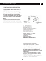
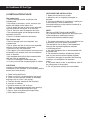
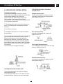
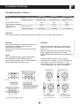
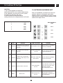
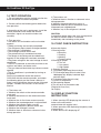
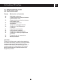
EN
Installation Manual
Air Conditioner
DC Duct Type
Modelos:
MUCR 12 HF2
MUCR 18 HF2
MUCR 24 HF2
MUCR 30 HF2
MUCR 36 HF2
MUCR 48 HF2
MUCR 60 HF2
For correct installation, read this manual before starting installation.
This manual may be subject to change without notice for purpose of improvement..
Air Conditioner DC Duct Type
EN
ÍNDICE
1. INSTALLATION INFORMATION..............................................................................................................2
2. ACCESORIES.........................................................................................................................................2
3. CAUTIONS ON REMOTE CONTROLLER INSTALLATION....................................................................2
4. INSTALATION PLACE.............................................................................................................................3
5. INDOOR UNIT INSTALLATION...............................................................................................................4
6. INSTALL THE MAIN BODY......................................................................................................................5
7. PANEL INSTALLATION...........................................................................................................................6
8. INSTALL THE CONNECTING PIPE........................................................................................................7
9. REFRIGERANT PIPE CONNECTION....................................................................................................8
10. CONNECT THE DRAIN PIPE...............................................................................................................9
11. WIRING.................................................................................................................................................9
12. WIRING CHART..................................................................................................................................10
13. NETWORK ADDRESS SET................................................................................................................13
14. TEST OPERATION..............................................................................................................................14
15. POINT CHECK INSTRUCTION...........................................................................................................14
16. DISPLAY FUNCTION INSTRUCTION.................................................................................................14
17. MALFUNCTION CODE OF OUTDOOR UNIT.....................................................................................15
Air Conditioner DC Duct Type
EN
1. INSTALLATION INFORMATION
• To install properly, please read this manual at
first. The air conditioner must be installed by
qualified persons.
• When installing the indoor unit or its tubing,
please follow this manual as strictly as possible.
• When all the installation work is finished, please
turn on the power only after a thorough check.
• No further announcement if there is any change
of this manual caused by product improvement.
NOTE
The installor should illustrate to users how to
correctly use and maintain the air-conditioner, as
well as remind users to carefully read and keep
both Installation Manual and Owner's Manual well.
2. ACCESORIES
Installation manual (1)
Remote controller subassembly (1)
Pipe insulation material (2)
Accessory drain pipe (1)
Adhesive tape for seal (1)
Remote controller & its frame
1. Remote controller (1)
2. Frame (1)
3. Mounting screw (2)
4. Alkaline dry batteries (AM4)(2)
5. Remote controller manual (1)
3.CAUTIONS ON REMOTE
CONTROLLER INSTALLATION
• Never throw or beat the controller.
• Before installation, operate the remote controller
to determine its location in a reception range.
• Keep the remote controller at least 1mapart from
the nearest TV set or stereo equipment. (It is
necessary to prevent image disturbances or noise
interferences.)
• Do not install the remote controller in a place
exposed to direct sunlight or close to a heating
source, such as a stove.
• Note that the positive and negative poles are in
right positions when loading batteries.
2
Air Conditioner DC Duct Type
EN
NOTES BEFORE INSTALLATION
1. Select the correct carry-in path.
2. Move this unit as originally packaged as
possible.
3. If the air conditioner is installed on a metal part
of the building, it must be electrically
insulated according to the relevant standards to
electrical appliances
4. INSTALLATION PLACE
The Indoor Unit
• There is enough roomfor installation and
maintenance.
• The ceiling is horizontal, and its structure can
endure the weight of the indoor unit.
• The air outlet and the air inlet are not impeded,
and the influence of external air is the least.
• The air flow can reach throughout the room.
• The connecting pipe and drainpipe could be
extracted out easily.
• There is no direct radiation fromheaters
NOTE
Remark per EMC Directive 89/336/EEC
For to prevent flicker impressions during the start
of the compressor (technical process),
following installation conditions apply.
The Outdoor Unit
• There is enough room for installation and
maintenance.
• The air outlet and the air inlet are not impeded,
and can not be reached by strong wind.
• The place is dry and ventilative.
• The support is flat and horizontal and can stand
the weight of the outdoor unit. And no additional
noise or vibration.
• Your neighborhood will not feel uncomfortable
with the noise or expelled air.
• There is no leakage of combustible gas.
• It is easy to install the connecting pipe or cables.
1. The power connection for the air conditioner has
to be done at the main power distribution.
The distribution has to be of a low impedance,
normally the required impedance reaches
a 32Afusing poinat t.
2. No other equipment has to be connected with
this power line.
3. For detailed installation acceptance, please
refer to your contract with the power supplier
if restrictions do apply for products like washing
machines, air conditioners or electrical
ovens.
4. For power details of the air conditioner, refer to
the rating plate of the product.
5. For any question contact your local dealer.
CAUTIONS
Location in the following places may cause
malfunction of the machine. (If unavoidable, please
consult your local dealer.)
a. There exists petrolatum.
b. There is salty air surrounding(near the coast).
c. There is caustic gas(the sulfide, for example)
existing in the air (near a hot spring).
d. The Volt vibrates violently(in the factories).
e. In buses or cabinets.
f. In kitchen where it is full of oil gas.
g. There is strong electromagnetic wave existing.
h. There are inflammable materials or gas.
i. There is acid or alkaline liquid evaporating.
j. Other special conditions.
3
Air Conditioner DC Duct Type
EN
THE INSTALLATION OF HANGING
SCREW BOLTS
5. INDOOR UNIT INSTALLATION
Install the main body
Installing Ø10 hanging screw bolts. (4 bolts)
Please refer to the following figure for the distance
measurement between the screw bolts.
Please install with Ø10 hanging screw bolts.
The handling to the ceiling varies fromthe
constructions, consult the construction personnels
for the specific procedures.
Wooden construction
Put the square timber traversely over the
roof beam, then install the hanging screw
bolts. (Refer to Chart 1)
1. The ceiling where the works will be done must
be flat. Consolidate the roof beamfor possible
vibration.
2. Cut off the roof beam.
3. Strengthen the place cut off, and consolidate
the roof beam.
New concrete bricks
Inlaying or embedding the screw bolts.
(Refer to Chart 2)
Carry out the pipe and line operation in the ceiling
after finishing the installation of the main body.
While choosing where to start the operation,
determine the direction of the pipes to be drawn
out. Especially in case there is a ceiling, position
the refrigerant pipes, drain pipes, indoor & outdoor
lines to the connection places before hanging up
the machine.
The installation of hanging screw bolts.
For Original concrete bricks
Use embedding screw bold, crock and stick
harness. (Refer to Chart 3)
Steel roof beamstructre
Install and use directly thesupporting angl
steel. (Refer to chart 4)
OVERHANGING THE INDOOR UNIT
(1)Overhang the indoor unit onto the hanging
screw bolts with block
(2) Position the indoor unit in a flat level by using
the level indicator, unless it may cause leakage.
4
Air Conditioner DC Duct Type
EN
6. DIMENSIONS
AIR RETURN OPENING SIZE
5
Air Conditioner DC Duct Type
EN
Dimensions
A
D
E
F
G
H
920 210 635 570
65
713
35
119
1140 210 635 570
65
933
35
119 1035 200
80 1180 350
920 270 635 570
65
713
35
179 815 260
20
30~36 1140 270 775 710
65
933
35
179 1035 260
20 1180 490
48~60 1200 300 865 800
80
968
40
204 1094 288
45 1240 500
12~18
24
B
C
Size of
mounted lug
Air returning
Air Outlet
I
J
K
815 200
80
L
960 350
960 350
7. ADJUST AIRVENTILATED DIRECTION
1.- Take off ventilation panel and flange, cut off
the staples at side rail
2.- Stick the attached seal sponge as per
indicating place in the folowing fig, and
then change the mounting positions of
air return panel and air return flange
Air return flange
Dentilation panel
Seal sponge
Side rail
3.- When install the filter mesh, please plug it
into flange inclined from air return, and then
push up.
4.- The installation has finish, upon filter
mesh which fixing blocks have been
insert to the flange positional holes.
6
M
Air Conditioner DC Duct Type
EN
8. INSTALL THE CONNECTING PIPE
CAUTION
Check whether the height drop between the indoor
unit and outdoor unit, the length of refrigerant pipe,
and the number of the bends meet the following
requirements:
30
MUCR-HF 12 18 24 1F
Outdoor Unit Top 5 12 12 15
MAX .
HEIGHT Outdoor Unit Bottom 5 9 9 9
Max. length 10 25 25 25
30
3F
20
12
30
36
1F
20
12
30
36
3F
20
12
30
48
1F
25
20
50
48
3F
30
20
50
NOTICE FOR BENDABLE PIPE
• The bending angle should not exceed 90 .
• Bending position is preferably in the middle of the
bendable pipe. The larger the bending radius the
better it is.
• Do not bend the pipe more than three times.
60
30
20
50
BEND THE CONNETCTING PIPE OF SMALL
WALL THICKNESS
• Cut out a desired concave at the bending part of
the insulating pipe.
• Then expose the pipe (cover it with tapes after
bending).
• To prevent collapsing or deforming, please bend
the pipe at its biggest radius.
• Use bender to get a small radius pipes.
The outdoor unit is factory charged with refrigerant.
Some systems require additional
charging of regrigerant depending on pipe lengths.
The additional refrigerant to be charged can be
calculated fromthe following formule:
R = T X (L-5)m
R(g): Additional regrigerant to be carged
T(g): The length of the liquid pipe
L(m):The quantity of charged refrigerant per meter
Use the market brass pipe
Be sure to use the same insulating materials when
you buy the brass pipe (more than 9mmthick).
1. Locate The Pipes
1) Drill a hole in the wall (suitable just for the size
of the wall conduit, 90mmin general), then set on
the fittings such as the wall conduit and its cover.
2) Bind the connecting pipe and the cables
together tightly with binding tapes. Do not let air in,
which will cause water leakage by condensation.
3) Pass the bound connecting pipe through the
wall conduit fromoutside. Be careful of the pipe
allocation to do no damage to the tubing.
4) Connect the pipes.
5) Then, open the stemof stop valves of the
outdoor unit to make the refrigerant pipe
connecting the indoor unit with the outdoor unit
fluently flow.
6) Be sure of no leakage by checking it with leak
detector or soap water.
7) Cover the joint of the connecting pipe to the
indoor unit with the soundproof/insulating sheath
(fittings), and bind it well with the tapes to prevent
leakage.
CAUTION
• Do not let air, dust, or other impurities fall in the
pipe systemduring the time of installation.
• The connecting pipe should not be installed until
the indoor and outdoor units have been fixed
already.
• Keep the connecting pipe dry, and do not let
moisture in during installation.
CONNECT THE DRAIN PIPE
Measure the necessary length of the connecting
pipe, and make it by the following way.
1) Connect the indoor unit at first, then the outdoor
unit.Bend the tubing in proper way. Do not harm to
them.
CAUTION
Daub the surfaces of the flare pipe and the joint
nuts with frozen oil, and wrench it for 3~4 rounds
with hands before fasten the flare nuts.
(Refer to chart 16)
Be sure to use two wrenches simultaneously when
you connect or disconnect the pipes.
2) The stop value of the outdoor unit should be
closed absolutely (as original state). Every time
you connect it, first loosen the nuts at the part of
stop value , then connect the flare pipe
immediately (in 5 minutes). If the nuts have been
loosened for a long time, dusts and other
Chart 16
7
Chart 17
Chart 18
Air Conditioner DC Duct Type
EN
9. REFRIGERANT PIPE
CONNECTION
Flaring
Chart 19
The necessary filling amount of refrigerant
Refrigerant volume to be added is calculated
according to outdoor unit installation manual .
Be sure to add refrigerant measuring by a scale.
L: The length of the pipe
Please record the quantity added and store it
carefully for future maintenance.
Chart 20
1. Cut a pipe with a pipe cutter.
2. Insert a flare nut into a pipe and flare
the pipe.
Outside-diameter
(mm)
Expel the air with a vacuumpump
(Refer to Chart 22)
(please refer to its manual for the way of using
manifold value)
• Loosen and remove the maintenance nuts of
stop values A and B, and connect the charge hose
of the manifold value with the maintenance
terminator of stop valueA. (Be sure that stop
Chart 22
values A and B are both
closed)
• Connect the joint of
the charge hose with the vacuumpump.
• Open the Lo-lever of the manifold value
completely.
• Turn on the vacuum pump. At the beginning of
pumping, loosen the maintenance terminator nut
of stop valueB a little to check whether the air
comes in (the sound of the pump changes, and
the indicator of compound meter turns below zero).
Then fasten the nut.
• When the pumping has finished, close the Lolever of the manifold value completely and turn off
the vacuum pump.
When you have pumped for over 15 minutes,
please confirm that the indicator of multi-meter is
on 1.0x10⁵ Pa(-76cmHg).
• Loosen and remove the quadrangle cover of stop
values Aand Bto open stop value A and B
completely, then fasten them.
• Disassemble the charge hose fromthe repairmouth of stop value A, and fasten the nut.
A(mm)
Ø6.35
Ø9.53
Ø12.7
Ø16
Ø19
Max
Min
8.7
12.4
15.8
19.0
23.3
8.3
12.0
15.4
18.6
22.9
Fasten the nuts
Put the connecting tubing at the proper position,
wrench the nuts with hands, then fasten it with a
wrench.( Refer to Chart 21)
Chart 21
CAUTION
Too large torque will harm the bellmouthing
and too small will cause leakage. Please
determine the torque according to Table 2.
Tubing Size
Ø6.35
Ø9.53
Ø12.7
Ø16
Ø19
Torque
14.4~17.2 N.m
32.7~39.9 N.m
49.5~60.3 N m
61.8~75.4 N m
92.7~118.6 N m
Table2
CAUTION
All the stop values should be opened before test
operation. Each air conditioner has two stop
values of different sizes on the side of the outdoor
unit which operate as Lo-stop value and Hi-stop
value, respectively.
8
Air Conditioner DC Duct Type
EN
11. WIRING
Check the leakage
Check all the joints with the leak detector or soap
water.
Attaching wiring
1. The air conditioner should use separate power
supply with rated voltage
2. The external power supply to the air conditioner
should have ground wiring, which is linked to the
ground wiring of the indoor and outdoor unit.
3. The wiring work should be done by qualified
persons according to circuit drawing.
4. Aleakage protector should be installed
according to the National Standard concerning
electrical appliance.
5. Be sure to locate the power wiring and the
signal wring well to avoid cross-disturbance and
their contact with connecting pipe or stop value
body.
6. The wiring attached to this air conditioner is
10m long. Be sure to prolong it with wiring of the
same type and proper length if necessary.
Generally, do not twist two wiring together unless
the joint is soldered well and covered with
insulator tape.
7. Do not turn on the power until you have checked
carefully after wiring.
Insulation
Be sure to with insulating materials cover all the
exposed parts of the flare pipe joints and
refrigerant pipe on the liquid-side and the gas-side.
Ensure that there is no gap between them.
Incomplete insulation may cause water
condensation.
10. CONNECT THE DRAIN PIPE
1. Install indoor unit drain pipe
The outlet has PTI screw bread, Please use
sealing materials and pipe sheath (fitting) when
connecting PVC pipes.
CAUTION
• The drain pipe of indoor unit must be heat
insulated, or it will condense dew, as well as the
connections of the indoor unit.
• Hard PVC binder must be used for pipe
connection, and make sure there is no leakage.
• With the connection part to the indoor unit,
please be noted not to impose pressure on the
side of indoor unit pipes.
• When the declivity of the drain pipe downwards
is over 1/100, there should not be any win ding.
• The total length of the drain pipe when pulled out
traversely shall not exceed 20m, when the pipe is
over long, a prop stand must be installed to
prevent winding.
• Refer to the figures on the right for the
installation of the pipes.
2. Drainage test
Check whether the drainpipe is unhindered
New built house should have this test done before
paving the ceiling.
Remove the test cover, and stow water of about
2000ml to the water receiver through
Test Cap
9
Air Conditioner DC Duct Type
EN
12. WIRING CHART
10
Air Conditioner DC Duct Type
EN
12. WIRING CHART
INDOOR UNIT
Power Supply1-Phase
220-240V
(3-core cable 3x1.0mm²)
3-core shielded cable
to CCM (3x0.5mm²)
OUTDOOR UNIT
3-core shielded cable
(3 x 0.5 mm²)
Power Supply1-Phase
220-240V
(3-core cable 3x4 mm²)
Models 18-60 (with 1-Phase outdoor unit)
INDOOR UNIT
3-core shielded cable
to CCM (3x0.5mm²)
Power Supply1-Phase
220-240V
(3-core cable 3x1.0mm²)
OUTDOOR UNIT
3-core shielded cable
(3 x 0.5 mm²)
Power Supply1-Phase
220-240V
(5-core cable 5x2.5 mm²)
Models 36-60 (with 3-Phase outdoor unit)
11
Air Conditioner DC Duct Type
EN
The Specification of Power
Type
Power
Phase
Frequency and volt
Circuit breaker / Fuse (A)
Indoor unit power wiring(mm2)
Indoor/Outdoor
connecting
wiring
2
(mm )
18000 Btu/h
24000 Btu/h
36000-60000 Btu/h
1-Phase
1-Phase
3-Phase
220-240V - 50 Hz
220-240V - 50 Hz
380-415V - 50 Hz
30/25
40/25
40/25
3 x 1,0
3 x 1.0
3 x 1,0
Outdoor unit power
3 x 2,5
3 x 2,5
5 x 2,5
Weak electric signal
3 core shield wire
3 core shield wire
3 core shield wire
CAUTION
The reserved function is indicated in broken line table,users can select it when necessary
CAUTION
The reserved function is indicated in broken line
table,users can select it when necessary
Terminal Board Diagram
Please refer to the indoor unit wiring diagramfor
the wiring.
CONTROL
As per the different usages to set the moving
switch on the PCB in the electric control box of
indoor unit.
After the setting , be sure to cut down the main
power supply switch, then turn it on again
Setting would be invalid without disconnecting the
power.
NOTE
The air-conditioners can connect with Central
Control Monitor (CCM). Before operation,
please wiring correctly and set system address
and network address of indoor units.
Please number the indoor units during the
installation. For example, for the first outdoor unit
,the number of the first indoor unit is 1-1, the
second indoor unit is 1-2, and the set address is
1 and 2 respectively, the others is analogical.
Model 1 show the address
'0-F' respectively,
that is, '0-15' indoor unit
12
Model 2 show the address
'0-F' respectively,
that is, '16-31' indoor unit
Air Conditioner DC Duct Type
EN
CAUTION
1.The system together have 64units
(0-63),everyone has only system addresscode,
If two addresses are the same in one system,
the abnormal operation will occur.
2.Please switch off the power before
setting,otherwise the unexpected error will occur.
Código interruptor de palanca
Capacidad (Btu/h)
4
5
18000
24000
8
36000
9
9
48000
60000
13. NETWORK ADDRESS SET
Every air-conditioner in network has only one
network address to distinguish each other.
Address code of air-conditioner in LAN is set by
code switch on Network Interface Module (NIM),
and the set range is 0-63
Network address
code
00-15
16-31
32-47
48-63
N°
Type
Contents
LED Lamp Flash
Remarks
Run lamp flashes at 2.5 Hz
After the malfunctions disappear,
it restores automatically
1
The evaportator sensor check point
Malfunction is abnormal, or room temp. sensor
is abnormal
2
Indoor/Outdoor unit comunication
Malfunction is abnormal
The timer lamp flashes
at 2.5 Hz
After the malfunctions disappear,
it restores automatically
3
Condenser sensor check point is
Malfunction abnormal or outdoor temp. sensor
is abnormal
All the indoor alarm lamps
flash at 0,5 Hz
After the malfunctions disappear,
it restores automatically
Alarm lamp flashes
at 2.5 Hz
If the malfunctions can't be solved
in three min. all the indoor alarm
lamp flashes at 0,5Hz.
Turn off the power to restore.
Defrost lamp flashes
at 2.5 Hz
When the indoor unit turns to
heating mode or is turned off, the
alarm will disappear
4
5
Malfunction Water level switch is abnormal
Alarm
Mode conflict
13
Air Conditioner DC Duct Type
EN
14. TEST OPERATION
2) The outdoor unit
a. Whether there is vibration or abnormal noise
during operation.
b. Whether the generated wind, noise, or
condensed water by the air conditioner have
influenced your neighborhood.
c. Whether any of the refrigerant is leaked.
1.The test operation must be carried out after the
entire installation has been completed.
2. Please confirm the following points before the
test operation:
3. According to the user's requirement, install the
remote controller frame where the remote
controller's signal can reach the indoor unit
smoothly.
CAUTION
A protection device delays the start of compressor
for about 3 minutes when it is restarted
immediately after switching on the power.
4. Test operation
• The indoor unit and outdoor unit are installed
properly.
• Tubing and wiring are correctly completed.
• The refrigerant pipe systemis leakage-checked.
• The drainage is unimpeded.
• The heating insulation works well.
• The ground wiring is connected correctly.
• The length of the tubing and the added stow
capacity of the refrigerant have been recorded.
• The power voltage fits the rated voltage of the air
conditioner.
• There is no obstacle at the outlet and inlet of the
outdoor and indoor and indoor units.
• The gas-side and liquid-side stop values are both
opened.
• The air conditioner is pre-heated by turning on
the power.
Set the air conditioner under the mode of
COOLING with the remote controller, and check
the following points per the Owner's Manual. If
there is any malfunction, please resolve it through
chapter "Troubles And Causes" in the Owner's
Manual.
15. POINT CHECK INSTRUCTION
0.Normally display
1.Running mode:
0.Stand by
2.Cooling
3.Heating
4.Forced cooling
2.Runnig fan speed
0. Turn off
1. Low speed
2. High speed
3. Capacity demand
4. T3-Outdoor pipe temp.(Actual value)
5. TP-Discharge temp.(Actual value,if over
100degree,only display hundreds digit
and tens digit)
6.T4-Ambient temp.(Actual value)
7.Current of compressor
8.PMv opening degree
9.The last error or protection code
(Display 00 if no error)
10. Display
1) The indoor unit
a. Whether the switch on the remote controller
works well.
b. Whether the buttons on the remote controller
works well.
c. Whether the air flow louver moves normally.
d. Whether the roomtemperature is adjusted well.
e. Whether the indicator lights normally.
f. Whether the temporary buttons works well.
g. Whether the drainage is normal.
h. Whether there is vibration or abnormal noise
during operation.
16. DISPLAY FUNCTION
INSTRUCTION
1. When stand by,LED displaying the amount of
indoor units online which
communicate with outdoor units
2. When operation,LED displaying frequecny value
of compressor
3. When defrost,LED displaying dF
14
Air Conditioner DC Duct Type
EN
17. MALFUNCTION CODE
OF OUTDOOR UNIT
Display
E0
E2
E3
E4
E5
P0
P1
P2
P3
P4
P5
P6
Malfunction or Protection
EEPROM malfunction
Communication malfunction between
indoor/outdoor units
Communication malfunction between
DSP/outdoor units
T4 temperature sensor
malfunction
Compressor Voltage protection
Compressor Top Temperature
Protection
High Pressure Protection
Low Pressure Protection
Compressor current protection
Compressor discharge temperature
protection
Protección de alta temperatura
Module protection
CAUTION
Please cut off the power supply when appearing
the above malfunction, check the voltage provided
is out of range, check if the installation of airconditioner is correct, then electrify again after 3
minutes power off. If the problemis still existent,
please contact the local service station or the
equipment provider.
15
EN
Instalation Manual
®
SALVADOR ESCODA S.A.
BARCELONA
Head Office:
Provença, 392, pl 1 & 2
08025 BARCELONA
Export Department:
[email protected]
Tel. + 34 93 446 27 81
Fax + 34 93 446 27 96