1
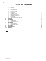
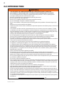
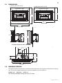
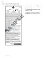
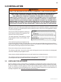
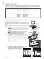
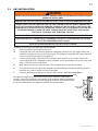
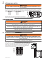
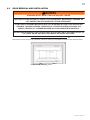
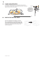
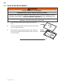
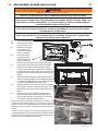
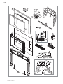
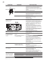
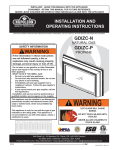
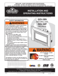
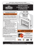
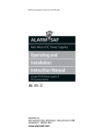
1 INSTALLER: LEAVE THIS MANUAL WITH THE APPLIANCE. CONSUMER: RETAIN THIS MANUAL FOR FUTURE REFERENCE. INSTALLATION AND OPERATING INSTRUCTIONS CERTIFIED UNDER CANADIAN AND AMERICAN NATIONAL STANDARDS: CSA 2.33, ANSI Z21.88 FOR VENTED GAS FIREPLACE HEATERS. CDIZC-N CERTIFIED FOR CANADA AND UNITED STATES USING ANSI/CSA METHODS. SAFETY INFORMATION ! NATURAL GAS WARNING CDIZC-P If the information in these instructions are not followed exactly, a fire or explosion may result causing property damage, personal injury or loss of life. PROPANE - Do not store or use gasoline or other flammable vapors and liquids in the vicinity of this or any other appliance. - WHAT TO DO IF YOU SMELL GAS: • Do not try to light any appliance. • Do not touch any electrical switch; do not use any phone in your building. • Immediately call your gas supplier from a neighbour’s phone. Follow the gas supplier’s instructions. • If you cannot reach your gas supplier, call the fire department. - Installation and service must be performed by a qualified installer, service agency or the supplier. This appliance may be installed as an OEM installation in manufactured home (USA only) or mobile home and must be installed in accordance with the manufacturer’s instructions and the Manufactured Home Construction and Safety Standard, Title 24 CFR, Part 3280, in the United States or the Standard for Installation in Mobile Homes, CAN/CSA Z240 MH, in Canada. This appliance is only for use with the type(s) of gas indicated on the rating plate. A conversion kit is supplied with the appliance. ! WARNING HOT GLASS WILL CAUSE BURNS. DO NOT TOUCH GLASS UNTIL COOLED. NEVER ALLOW CHILDREN TO TOUCH GLASS. Wolf Steel Ltd., 24 Napoleon Rd., Barrie, ON, L4M 0G8 Canada / 103 Miller Drive, Crittenden, Kentucky, USA, 41030 Phone (705)721-1212 • Fax (705)722-6031 • www.continentalfireplaces.com • [email protected] $10.00 1.24A W415-0224 / G / 04.05.11 2 TABLE OF CONTENTS 1.0 2.0 3.0 INSTALLATION OVERVIEW INTRODUCTION 3 4 2.1 2.2 2.3 2.4 2.5 5 5 6 7 8 INSTALLATION 3.1 3.2 3.3 3.4 4.0 5.0 6.0 7.0 8.0 9.0 10.0 11.0 DIMENSIONS MINIMUM OPENING GENERAL INSTRUCTIONS GENERAL INFORMATION RATING PLATE INFORMATION LEVELLING THE APPLIANCE CHIMNEY CONNECTION GAS INSTALLATION OPTIONAL WALL SWITCH 9 9 10 11 12 FINISHING 12 4.1 4.2 4.3 4.4 4.5 4.6 12 13 14 14 15 15 MINIMUM MANTEL CLEARANCES DOOR REMOVAL AND INSTALLATION LOG PLACEMENT GLOWING EMBERS LOGO PLACEMENT ALUMINUM EXTRUSION TRIM KIT INSTALLATION OPERATION ADJUSTMENTS 16 17 6.1 6.2 6.3 6.4 17 17 18 18 PILOT BURNER ADJUSTMENT VENTURI ADJUSTMENT FLAME CHARACTERISTICS RESTRICTING VERTICAL VENTS MAINTENANCE 19 7.1 7.2 7.3 7.4 19 19 20 21 CARE OF GLASS CARE OF PLATED PARTS DOOR GLASS REPLACEMENT REPLACEMENT BLOWER INSTALLATION REPLACEMENTS TROUBLE SHOOTING WARRANTY SERVICE HISTORY NOTE: changes, other than editorial, are denoted by a vertical line in the margin. W415-0224 / G / 02.28.11 22 25 27 28 3 1.0 INSTALLATION OVERVIEW Trim, see “ALUMINUM EXTRUSION TRIM KIT INSTALLATION” section. Venting, see “CHIMNEY CONNECTION” section. Door, see “DOOR REMOVAL AND INSTALLATION” section. Logs, see “LOG PLACEMENT” section. Rating Plate, see “RATING PLATE INFORMATION” section. W415-0224 / G / 04.05.11 4 2.0 INTRODUCTION ! • • • • • • • • • • • • • • • • • • • • • • • • • • • • • • WARNING THIS APPLIANCE IS HOT WHEN OPERATED AND CAN CAUSE SEVERE BURNS IF CONTACTED. ANY CHANGES TO THIS APPLIANCE OR IT’S CONTROLS CAN BE DANGEROUS AND IS PROHIBITED. Do not operate appliance before reading and understanding operating instructions. Failure to operate appliance according to operating instructions could cause fire or injury. Risk of fire or asphyxiation do not operate appliance with fixed glass removed. Do not connect 110 volts to the control valve. Risk of burns. The appliance should be turned off and cooled before servicing. Do not install damaged, incomplete or substitute components. Risk of cuts and abrasions. Wear protective gloves and safety glasses during installation. Sheet metal edges may be sharp. Do not burn wood or other materials in this appliance. Children and adults should be alerted to the hazards of high surface temperature and should stay away to avoid burns or clothing ignition. Young children should be carefully supervised when they are in the same room as the appliance. Toddlers, young children and others may be susceptible to accidental contact burns. A physical barrier is recommended if there are at risk individuals in the house. To restrict access to an appliance or stove, install an adjustable safety gate to keep toddlers, young children and other at risk individuals out of the room and away from hot surfaces. Clothing or other flammable material should not be placed on or near the appliance. Due to high temperatures, the appliance should be located out of traffic and away from furniture and draperies. Ensure you have incorporated adequate safety measure to protect infants/toddlers from touching hot surfaces. Even after the appliance is out, the glass and/or screen will remain hot for an extended period of time. Check with your local hearth specialty dealer for safety screens and hearth guards to protect children from hot surfaces. These screens and guards must be fastened to the floor. Any safety screen or guard removed for servicing must be replaced prior to operating the appliance. The appliance is a vented gas-fired appliance. Do not burn wood or other materials in the appliance. It is imperative that the control compartments, burners and circulating blower and its passageway in the appliance and venting system are kept clean. The appliance and its venting system should be inspected before use and at least annually by a qualified service person. More frequent cleaning may be required due to excessive lint from carpeting, bedding material, etc. The appliance area must be kept clear and free from combustible materials, gasoline and other flammable vapors and liquids. Under no circumstances should this appliance be modified. This appliance must not be connected to a chimney flue pipe serving a separate solid fuel burning appliance. Do not use this appliance if any part has been under water. Immediately call a qualified service technician to inspect the appliance and to replace any part of the control system and any gas control which has been under water. Do not operate the appliance with the glass door removed, cracked or broken. Replacement of the glass should be done by a licensed or qualified service person. Do not strike or slam shut the appliance glass door. When equipped with pressure relief doors, they must be kept closed while the appliance is operating to prevent exhaust fumes containing carbon monoxide, from entering into the home. Temperatures of the exhaust escaping through these openings can also cause the surrounding combustible materials to overheat and catch fire.Only doors / optional fronts certified with the unit are to be installed on the appliance. Only doors / optional fronts certified with the unit are to be installed on the appliance. Keep the packaging material out of reach of children and dispose of the material in a safe manner. As with all plastic bags, these are not toys and should be kept away from children and infants. As with any combustion appliance, we recommend having your appliance regularly inspected and serviced as well as having a Carbon Monoxide Detector installed in the same area to defend you and your family against Carbon Monoxide. Ensure clearances to combustibles are maintained when building a mantel or shelves above the appliance. Elevated temperatures on the wall or in the air above the appliance can cause melting, discolouration or damage to decorations, a T.V. or other electronic components. This appliance uses and requires a fast acting thermocouple. Replace only with a fast acting thermocouple supplied by Wolf Steel Ltd. 3.1C W415-0224 / G / 02.28.11 2.1 5 DIMENSIONS 4 SIDED BACKER PLATE 3 SIDED BACKER PLATE ALUMINUM TRIM ALUMINUM TRIM 27" 36 1 / 2 " 44 7 / 8 " FRONT VIEW 44 7 / 8 " FRONT VIEW 20 3 / 4 " 15 1 / 2 " 14" 24 1 / 8 " 3 & 4 SIDED BACKER PLATES - SIDE VIEWS 25" 15 1 / 2 " 11 5 / 8 " 7 3/ 8" AIR INLET EXHAUST 5 ½" 10 9 / 16 " 15 1 / 2 " 3"Ø 4 15 / 16 " 36" TOP VIEW 2.2 MINIMUM OPENING This appliance must be recessed into a vented noncombustible wood-burning fireplace (prefabricated or masonry) only. The minimum fireplace opening size in which the appliance is to be installed is: HEIGHT 14.5" WIDTH 25" DEPTH 11" The minimum allowable chimney flue size is 6" round. W415-0224 / G / 04.05.11 6 2.3 GENERAL INSTRUCTIONS ! WARNING ALWAYS LIGHT THE PILOT WHETHER FOR THE FIRST TIME OR IF THE GAS SUPPLY HAS RUN OUT, WITH THE GLASS DOOR OPENED OR REMOVED. PROVIDE ADEQUATE CLEARANCE FOR SERVICING AND OPERATING THE APPLIANCE. PROVIDE ADEQUATE VENTILATION. NEVER OBSTRUCT THE FRONT OPENING OF THE APPLIANCE. OBJECTS PLACED IN FRONT OF THE APPLIANCE MUST BE KEPT A MINIMUM OF 48” FROM THE FRONT FACE OF THE UNIT. SURFACES AROUND AND ESPECIALLY ABOVE THE APPLIANCE CAN BECOME HOT. AVOID CONTACT WHEN THE APPLIANCE IS OPERATING. FIRE RISK. EXPLOSION HAZARD. HIGH PRESSURE WILL DAMAGE VALVE. DISCONNECT GAS SUPPLY PIPING BEFORE PRESSURE TESTING GAS LINE AT TEST PRESSURES ABOVE 1/2 PSIG. CLOSE THE MANUAL SHUT-OFF VALVE BEFORE PRESSURE TESTING GAS LINE AT TEST PRESSURES EQUAL TO OR LESS THAN 1/2 PSIG. USE ONLY WOLF STEEL APPROVED OPTIONAL ACCESSORIES AND REPLACEMENT PARTS WITH THIS APPLIANCE. USING NON-LISTED ACCESSORIES (BLOWERS, DOORS, LOUVRES, TRIMS, GAS COMPONENTS, VENTING COMPONENTS, ETC.) COULD RESULT IN A SAFETY HAZARD AND WILL VOID THE WARRANTY AND CERTIFICATION. THIS GAS APPLIANCE SHOULD BE INSTALLED AND SERVICED BY A QUALIFIED INSTALLER to conform with local codes. Installation practices vary from region to region and it is important to know the specifics that apply to your area, for example in Massachusetts State: • This product must be installed by a licensed plumber or gas fitter when installed within the commonwealth of Massachusetts. • The appliance damper must be removed or welded in the open position prior to installation of a appliance insert or gas log. • The appliance off valve must be a “T” handle gas cock. • The flexible connector must not be longer than 36 inches. • A Carbon Monoxide detector is required in all rooms containing gas fired appliances. • The appliance is not approved for installation in a bedroom or bathroom unless the unit is a direct vent sealed combustion product. The installation must conform with local codes or, in absence of local codes, the National Gas and Propane Installation Code CSA B149.1 in Canada, or the National Fuel Gas Code, ANSI Z223.1 / NFPA 54 in the United States. Suitable for mobile home installation if installed in accordance with the current standard CAN/CSA Z240MH Series, for gas equipped mobile homes, in Canada or ANSI Z223.1 and NFPA 54 in the United States. www.nficertified.org We suggest that our gas hearth products be installed and serviced by professionals who are certified in the U.S. by the National Fireplace Institute® (NFI) as NFI Gas Specialists As long as the required clearance to combustibles is maintained, the most desirable and beneficial location for an appliance is in the center of a building, thereby allowing the most efficient use of the heat created. The location of windows, doors and the traffic flow in the room where the appliance is to be located should be considered. If possible, you should choose a location where the vent will pass through the house without cutting a floor or roof joist. If the appliance is installed directly on carpeting, vinyl tile or other combustible material other than wood flooring, the appliance shall be installed on a metal or wood panel extending the full width and depth. Some appliances have optional fans or blowers. If an optional fan or blower is installed, the junction box must be electrically connected and grounded in accordance with local codes, use the current CSA C22.1 Canadian Electrical Code in Canada or the ANSI/NFPA 70 National Electrical code in the United States. 4.1A W415-0224 / G / 02.28.11 7 2.4 GENERAL INFORMATION FOR YOUR SATISFACTION, THIS APPLIANCE HAS BEEN TEST-FIRED TO ASSURE ITS OPERATION AND QUALITY! CDIZC NG LP Altitude (FT) 0-4,500 0-4,500 Max. Input (BTU/HR) 24,000 24,000 Max. Output (BTU/HR) 20,400 20,400 Efficiency (w/the fan on) 85% 85% A.F.U.E. (maximum value) 79% 79% Min. Inlet Gas Supply Pressure 4.5" Water Column 11" Water Column Max. Inlet Gas Supply Pressure 7" Water Column 13" Water Column 3.5" Water Column 10" Water Column Manifold Pressure (Under Flow Conditions) When the appliance is installed at elevations above 4,500ft, and in the absence of specific recommendations from the local authority having jurisdiction, the certified high altitude input rating shall be reduced at the rate of 4% for each additional 1,000ft. Expansion / contraction noises during heating up and cooling down cycles are normal and to be expected. This appliance is not approved for closet or recessed installations. It is approved for bathroom, bedroom and bed-sitting room installations and is suitable for mobile homes. The natural gas model is suitable for installation in a mobile home that is permanently positioned on its site and fuelled with natural gas. 65.5% CDIZC W415-0224 / G / 04.05.11 8 2.5 RATING PLATE INFORMATION HOMOLOGUE SELON LES NORMES: CSA 2.33-2009, ANSI Z21.88-2009 FOYER DE CHAUFFAGE AU GAZ AVEC EVACUATION. CERTIFIED UNDER: CSA 2.33-2009, ANSI Z21.88-2009 VENTED GAS FIREPLACE HEATER. 9700539 (WSL) 4001658 (NAC) GDIZC-N / CDIZC-N 0 - 4500FT 24,000 BTU/h 14,000 BTU/h 17,160BTU/h 4001657 (NGZ) 4001659 (WUSA) MODEL ALTITUDE/ELEVATION INPUT / ALIMENTATION REDUCED INPUT / ALIMENTATION REDUITE OUTPUT / RENDEMENT GDIZC-P / CDIZC-P 0 - 4500FT 24,000 BTU/h 15,000 BTU/h 17,160 BTU/h S A M P LE THIS FIREPLACE USES AND REQUIRES A FAST ACTING THERMOCOUPLE. REPLACE ONLY WITH A FAST ACTING THERMOCOUPLE SUPPLIED BY WOLF STEEL LTD. APPROVED FOR BEDROOM, M,, BATHROOM & BEDSITTING ROOM INSTALLATION. SUITABLE FOR MOBILE HOME INSTALLATION ION ON IF INSTALLED IN ACCORDANCE WITH THE CURRENT STANDARD CAN/CSA Z240MH SERIES ES S GAS EQUIPPED MOBILE HOMES, IN CANADA OR IN THE UNITED STATES THE MANUFACTURED RED HOME CONSTRUCTION AND SAFETY STANDARD, TITLE 24 CFR, PART 3280. WHEN THIS US STANDARD IS NOT APPLICABLE USE THE STANDARD FOR FIRE SAFETY CRITERIA IA FOR MANUFACTURED HOME INSTALLATIONS, SITES AND COMMUNITIES, ANSI / NFPA FPA 501A. A CE FOYER UTILISE ET REQUIERT UN THERMOCOUPLE À ACTION RAPIDE. REMPLACEZ TEEL LTÉE. UNIQUEMENT AVEC UN THERMOCOUPLE À ACTION RAPIDE DE WOLF STEEL HOMOLOGUE POUR INSTALLATION DANS UNE CHAMBRE A COUCHER, R, UNE SALLE DE BAIN ET UN STUDIO. APPROPRIE POUR INSTALLATION DANS UNE MAISON MOBILE SI SON INSTALLA INSTALLA-0MH H SERIE DE M MAISONS TION CONFORME AUX EXIGENCES DE LA NORME CAN/CSA Z240MH UX ETATS-UNIS S-UNIS DE LA NORME DE MOBILES EQUIPEES AU GAZ, EN VIGUEUR AU CANADA OU AUX CTUREES, TUREES, TITRE 24 CFR, SECTION SECURITE ET DE CONSTRUCTION DE MAISONS MANUFACTUREES, E PEUT ETRE APPLIQUEE, SE REFER REFERE 3280. DANS LE CAS OU CETTE NORME D'ETATS-UNIS NE REFERER E SECURITE CONTRE L'INCENDIE POU PO A LA NORME RELATIVE AU CRITERE DE MESURES DE POUR ACTURES, CTURES, LES SITES ET LES COMMU LES INSTALLATIONS DANS LES MAISONS MANUFACTURES, COMMUNAUTES, ANSI/NFPA 501A. STEADY STATE EFFICIENCY (NG/LP): 71.5% FAN OFF / 73% FAN ON ENT. ARRETE / 73% VENT VENT. FONCTION EFFICACITE CONSTANTE (GN/P): 71.5% VENT. FONCTIONNE O CANADA ONLY / L'EFFICACI L'EFFICACITE CON STEADY STATE EFFICIENCY APPLIES TO CONSTANTE ADA. A. S'APPLIQUENT SEULEMENT AU CANADA. AFUE (NG/LP) (GN/P): 65% MINIMUM AND MAXIMUM VERTICAL CAL VENT LENGTHS ARE 7 FEET AND 35 FEET EURS VERTICALES MINIMALES ET MA RESPECTIVELY. LES LONGUEURS MAXIMALES SONT 7 PIEDS ET NT. 35 PIEDS RESPECTIVEMENT. NCHES W.C. (NG) / 10 INCHES W MANIFOLD PRESSURE:: 3.5 INCHES W.C.(LP) ECTEUR : 3.5" D'UNE COLONNE D'E D'EAU PRESSION AU COLLECTEUR D'EAU(GN) / 10" D'UNE COLONNE D'EAU (P) SSU SSURE: .(NG) / 11" W.C. (LP) MIN SUPPLY PRESSURE: 4.5" W.C.(NG) LIMENTATION MIN : 4.5" LIMENTATIO 5" D'UNE CO COLON PRESSION D'ALIMENTATION COLONNE D'EAU (GN) / 11" D'UNE COLONNE D'EAU (P) PPLY Y PRESSURE: 7" W.C. (NG) / 13" W.C. W. (LP) W MAX. SUPPLY SION D'ALIMENTATION LIMENTATION MAX : 7" D'UNE D'UN COLONNE D'EAU (GN) / 13" D'UNE COLONNE PRESSION AU (P) D'EAU OR USE WITH GLASS DOORS CERTIF FOR CERTIFIED WITH THIS UNIT ONLY. UTILISER AVEC LES PORTES VITRE VITREES HOMOLOGUEES SEULEMENT AVEC CETTE UNITE. WARNIN DO NOT ADD ANY MAT WARNING: MATERIAL TO THE APPLIANCE, WHICH WILL COME IN CONTACT WITH THE FLAMES, OTHER TH THAN THAT SUPPLIED BY THE MANUFACTURER WITH THE APPLIANCE. AVERTISSEMENT : N'AJO N'AJOUTEZ PAS A CET APPAREIL AUCUN MATERIAU DEVANT ENTRER EN CONTA CONTACT AVEC LES FLAMMES AUTRE QUE CELUI QUI EST FOURNI AVEC CET APPAREIL AREIL PAR LE F FABRICANT. ELECTRICAL ECTRICAL RA RATING / CLASS.: 115V 1.5AMP 60HZ HE APPLIAN APPLIANC THE APPLIANCE MUST BE VENTED USING THE APPROPRIATE WOLF STEEL VENT KITS. SEE NERS IN OWNERS INSTALLATION MANUAL FOR VENTING SPECIFICS. PROPER REINSTALLATION AND L RESEALING IS NECESSARY AFTER SERVICING THE VENTAIR INTAKE SYSTEM. L'APPAREIL DOIT EVACUER SES GAZ EN UTILISANT L'ENSEMBLE D'EVACUATION PROPRE A WOLF STEEL. REFERER AU MANUEL D'INSTALLATION DE PROPRIETAIRE POUR L'EVACUATION PRECISE. IL EST IMPORTANT DE BIEN REINSTALLER ET RESCELLER L'EVENT APRES AVOIR ASSURE LE MAINTIEN DU SYSTEME DE PRISE D'AIR. WARNING: FOR INSTALLATION INTO A VENTED NON-COMBUSTIBLE FIREPLACE ONLY. THE MINIMUM FIREPLACE SIZE IS: HEIGHT 14 1/2”, DEPTH 11”, WIDTH 25”. THE MINIMUM INSIDE FLUE SIZE IS 7”. THE MINIMUM DISTANCE, FROM THE BOTTOM OF A COMBUSTIBLE MANTLE PROJECTING A MAXIMUM 3” FROM THE WALL TO THE TOP OF THE STANDARD TRIM IS 3”. SEE OWNERS MANUAL FOR GREATER EXTENSIONS. ATTENTION : POUR INSTALLATION DANS UN FOYER VENTILE EN MACONNERIE. LES DIMENSIONS MINIMUMS SONT: HAUTEUR 14 1/2”, PROFONDEUR 11”, LARGEUR 25”. LE DIAMETRE INTERIEUR MINIMUM DE CONDUIT D’EVACUATION EST DE 7”. LA DISTANCE MINIMALE, DU BAS DU MANTEAU COMBUSTIBLE FORMANT UNE PROJECTION MAXIMALE DE 3” DU MUR AU DESSUS DE LA GARNITURE NORMALE EST 3”. REFERER AU MANUEL D’INSTALLATION POUR DES EXTENSIONS PLUS GRANDES. NOT FOR USE WITH SOLID FUEL / UN COMBUSTIBLE SOLIDE NE DOIT PAS ETRE UTILSE AVEC CET APPAREIL WOLF STEEL LTD. 24 NAPOLEON ROAD, BARRIE, ON, L4M 0G8 CANADA SERIAL NUMBER GDIZC / CDIZC NO. DE SERIE W385-0198 / G W415-0224 / G / 02.28.11 INSTALLER: It is your responsibility to check off the appropriate box on the rating plate according to the model, venting and gas type of the appliance. For rating plate location, see “INSTALLATION OVERVIEW” section. This illustration is for reference only. Refer to the rating plate on the appliance for accurate information. 9 3.0 INSTALLATION ! WARNING RISK OF FIRE, MAINTAIN SPECIFIED AIR SPACE CLEARANCES TO VENT PIPE AND APPLIANCE. IF USING CO-AXIAL VENTING WITH SPACERS, THE VENT SYSTEM MUST BE SUPPORTED EVERY 3 FEET FOR BOTH VERTICAL AND HORIZONTAL RUNS. USE SUPPORTS OR EQUIVALENT NON-COMBUSTIBLE STRAPPING TO MAINTAIN THE REQUIRED CLEARANCE FROM COMBUSTIBLES. USE WOLF STEEL LTD. SUPPORT RING ASSEMBLY W010-0370 OR EQUIVALENT NON-COMBUSTIBLE STRAPPING TO MAINTAIN THE MINIMUM CLEARANCE TO COMBUSTIBLES FOR BOTH VERTICAL AND HORIZONTAL RUNS. SPACERS ARE ATTACHED TO THE INNER PIPE AT PREDETERMINED INTERVALS TO MAINTAIN AN EVEN AIR GAP TO THE OUTER PIPE. THIS GAP IS REQUIRED FOR SAFE OPERATION. A SPACER IS REQUIRED AT THE START, MIDDLE AND END OF EACH ELBOW TO ENSURE THIS GAP IS MAINTAINED. THESE SPACERS MUST NOT BE REMOVED. Clean out ashes from the inside of the wood-burning appliance. Make sure that the chimney and wood-burning appliance are in a clean and sound condition and constructed of non-combustible materials. If necessary have any repair work done by a qualified person before installing the insert. Remove the existing appliance damper or lock into an open position. WARNING: THIS FIREPLACE HAS BEEN CONVERTED FOR USE WITH A GAS FIREPLACE INSERT ONLY AND CANNOT BE USED FOR BURNING WOOD OR SOLID FUELS UNLESS ALL ORIGINAL Using screws, attach the appliance warning tag PARTS HAVE BEEN REPLACED AND THE FIREPLACE IS RE-APPROVED BY THE AUTHORITY HAVING JURISDICTION. to the inside of the firebox of the appliance into ATTENTION: CE FOYER A ETE CONVERTI AFIN D’ETRE UTILISE SEULEMENT which the insert is being installed. COMME FOYER ENCASTRE AU GAZ ET NE PEUT ETRE UTILSE POUR BRULER DU BOIS OU The sheet-metal parts of the appliance, in which the gas appliance insert is to be installed, must not be cut. TOUT AUTRE COMBUSTIBLE SOLIDE, SANS QUE TOUTES LES PIECES ORIGINALES AIENT ETE REMPLACEES ET QUE LE FOYER SOIT APPROUVE DE NOUVEAU PAR LES AUTORITES AYANT JURIDICTION. ADVERTENCIA: ESTA CHIMENEA SE REMODELÓ PARA USARSE SOLO CON UNA INSERCIÓN DE CHIMENEA A GAS Y NO PUEDE USARSE PARA QUEMAR MADERA NI COMBUSTIBLES SÓLIDOS, A MENOS QUE SE HAYAN REEMPLAZADO TODAS LAS PIEZAS ORIGINALES, Y LA AUTORIDAD JURISDICCIONAL LA HAYA VUELTO A APROBAR. W385-0199_B If the wood-burning factory-built appliance has no gas access hole(s) provided, an access hole of 1½ inch or less may be drilled through the lower sides or bottom of the appliance in a proper workman like manner. This access hole must be plugged with non-combustible insulation after the gas supply line has been installed. Ensure that existing chimney cleanouts fit properly. The refractory, glass doors, screen rails, screen mesh and log grates may be removed from the existing appliance before installing the gas appliance insert. Smoke shelves, shields and baffles may be removed if attached by mechanical fasteners. The ventilation openings in the existing appliance may be obstructed by the backer plates, aluminium trim etc. but these parts are not to be applied so as to have an airtight seal. 68.4 3.1 LEVELLING THE APPLIANCE Move the appliance close to its final position. This appliance is equipped with levelling screws located on the base. Level using the levelling screws. Levelling the appliance will eliminate rocking or excessive noise when the fan is in operation. Once the appliance is level, move it partially into place to allow for all connections to be made. It is not practical to level the appliance once it has been installed. Determine the required depth prior to installing the appliance and adjust the levelling screws accordingly. 67.2 W415-0224 / G / 04.05.11 10 3.2 CHIMNEY CONNECTION Chimney installation must conform to both national and local code requirements. The chimney must be lined with one 2" or 3" diameter liner for intake and one 3" diameter liner for exhaust. The minimum and maximum vent lengths are 10 and 35 feet respectively. Recommended kits come in 3 lengths: 1-2" & 1-3" DOUBLE PLY ALUMINUM LINER-INLET AND EXHAUST & 2-3" TO 2" REDUCER: GDI-2320KT VENT KIT 20FT GDI-2325KT VENT KIT 25FT GDI-2335KT VENT KIT 35FT 2-3" DOUBLE PLY ALUMINUM LINER-INLET AND EXHAUST: GDI-320KT VENT KIT 20FT GDI-325KT VENT KIT 25 FT GDI-335KT VENT KIT 35 FT While the liners must be continuous from the appliance to the terminal, to achieve the needed length, they may be coupled, using an approved coupler. We recommend that exhaust vents that pass through unheated spaces, such as tall exterior chimneys, be wrapped in a protective sleeve to minimize condensation and reverse flow symptoms. See Trouble Shooting for details. This appliance is approved for use with a 2" liner for air intake and a 3" liner for exhaust. For best performance, however, it is recommended to use two 3" FLASHING liners. PLATE If a 2" liner is used for the intake, it may be necessary to adjust the primary air shutter. 2” OVERLAP A. B. OUTSIDE: Slip the one end of a liner a minimum of 2" over the sleeve of the air terminal. Secure using 3 screws. Then seal the joint and screw heads with high temperature sealant. Repeat with the other liner. INTAKE EXHAUST NOTE: We recommend that the other end of the exhaust HI-TEMP liner be marked to eliminate the exhaust liner being SEALANT connected to the intake collar at the appliance. 2" OVERLAP Gently stretch the liners to the required lengths and insert into the chimney. Trim and fit the flashing plate to suit the chimney termination. Place the air terminal onto the top of the chimney. EXHAUST Make weather tight by sealing with caulking (not supplied). Fasten to the chimney with screws and plugs (not supplied). C. INSIDE: Attach and secure the flex liners to the vent connection assembly using the same procedure as before, ensuring that the marked exhaust liner is attached to the exhaust collar. D. Detach the two screws from the back of the firebox and remove the panel, as illustrated. E. Reaching in through the appliance, manoeuvre the vent connection assembly through the openings in the firebox top, taking care not to damage the gasket. In case of a low ceiling fireplace, the extension should be removed and reinstalled after the vent connection is secured to the firebox. Attach the restrictor plate to the centre stud and secure the assembly using the three studs and ¼-20 hex nuts. W415-0224 / G / 02.28.11 SEALANT HI-TEMP VENT CONNECTION ASSEMBLY INTAKE STUDS VENT CONNECTOR EXTENSION RESTRICTOR PLATE 11 3.3 GAS INSTALLATION ! WARNING RISK OF FIRE, EXPLOSION OR ASPHYXIATION. ENSURE THERE ARE NO IGNITION SOURCES SUCH AS SPARKS OR OPEN FLAMES. SUPPORT GAS CONTROL WHEN ATTACHING GAS SUPPLY PIPE TO PREVENT DAMAGING GAS LINE. ALWAYS LIGHT THE PILOT WHETHER FOR THE FIRST TIME OR IF THE GAS SUPPLY HAS RUN OUT WITH THE GLASS DOOR OPENED OR REMOVED. PURGING OF THE GAS SUPPLY LINE SHOULD BE PERFORMED BY A QUALIFIED SERVICE TECHNICIAN. ASSURE THAT A CONTINUOUS GAS FLOW IS AT THE BURNER BEFORE CLOSING THE DOOR. ENSURE ADEQUATE VENTILATION. FOR GAS AND ELECTRICAL LOCATIONS, SEE “DIMENSION” SECTION. ALL GAS CONNECTIONS MUST BE CONTAINED WITHIN THE APPLIANCE WHEN COMPLETE. HIGH PRESSURE WILL DAMAGE VALVE. DISCONNECT GAS SUPPLY PIPING BEFORE TESTING GAS LINE AT TEST PRESSURES ABOVE 1/2 PSIG. VALVE SETTINGS HAVE BEEN FACTORY SET, DO NOT CHANGE. Installation and servicing to be done by a qualified installer. A. Move the appliance into position and secure. B. If equipped with a flex connector the appliance is designed to accept a 1/2” gas supply. Without the connector it is designed to accept a 3/8” gas supply. The appliance is equipped with a manual shut off valve to turn off the gas supply to the appliance. C. Connect the gas supply in accordance to local codes. In the absence of local codes, install to the current CAN/CSA-B149.1 Installation Code in Canada or to the current National Fuel Gas Code, ANSI Z223.1 / NFPA 54 in the United States. D. When flexing any gas line, support the gas valve so that the lines are not bent or kinked. E. The gas line flex-connector should be installed to provide sufficient movement for shifting the burner assembly on it’s side to aid with servicing components. F. Check for gas leaks by brushing on a soap and water solution. Do not use open flame. 30.1A The appliance may now be pushed into its final position inside the wood burning fireplace. Secure the appliance to the fireplace using perforated strapping attached to the two securing holes on either side of the appliance as shown. We recommend that the trim be installed before the appliance is placed into its final position. SECURING HOLES W415-0224 / G / 04.05.11 12 3.4 OPTIONAL WALL SWITCH WARNING ! DO NOT CONNECT EITHER THE WALL SWITCH, THERMOSTAT OR GAS VALVE DIRECTLY TO 110 VOLT ELECTRICITY. For ease of accessibility, an optional remote wall switch or millivolt thermostat may be installed in a convenient location. Route a 2 strand, solid core millivolt wire from the valve to the wall switch or millivolt thermostat. The recommended maximum lead length depends on wire size: WIRE SIZE MAX. LENGTH 3 14 gauge 100 feet 16 gauge 60 feet 2 18 gauge 40 feet 1 Disconnect the existing wires from terminals 1 and 3 (from the ON/OFF switch) and replace with the leads from the wall switch / millivolt thermostat. 50.1 4.0 FINISHING WARNING ! RISK OF FIRE! NEVER OBSTRUCT THE FRONT OPENING OF THE APPLIANCE. THE FRONT OF THE APPLIANCE MUST BE FINISHED WITH ANY NON-COMBUSTIBLE MATERIALS SUCH AS BRICK, MARBLE, GRANITE, ETC., PROVIDED THAT THESE MATERIALS DO NOT GO BELOW THE SPECIFIED DIMENSION AS ILLUSTRATED. DO NOT STRIKE, SLAM OR SCRATCH GLASS. DO NOT OPERATE APPLIANCE WITH GLASS REMOVED, CRACKED, BROKEN OR SCRATCHED. FACING AND/OR FINISHING MATERIAL MUST NEVER OVERHANG INTO THE APPLIANCE OPENING. 72.1A 4.1 MINIMUM MANTEL CLEARANCES ! WARNING RISK OF FIRE, MAINTAIN ALL SPECIFIED AIR SPACE CLEARANCES TO COMBUSTIBLES. FAILURE TO COMPLY WITH THESE INSTRUCTIONS MAY CAUSE A FIRE OR CAUSE THE APPLIANCE TO OVERHEAT. ENSURE ALL CLEARANCES (I.E. BACK, SIDE, TOP, VENT, MANTEL, FRONT, ETC.) ARE CLEARLY MAINTAINED. WHEN USING PAINT OR LACQUER TO FINISH THE MANTEL, THE PAINT OR LACQUER MUST BE HEAT RESISTANT TO PREVENT DISCOLOURATION. Combustible mantel clearance can vary according to the mantel depth. Use the graph to help evaluate the clearance needed. These same requirements apply to any combustibles protruding on either side of the appliance. The minimum distance, from the bottom of a combustible mantel projecting 3" maximum from the wall to the top of the aluminum trim, is 3". 13 0 + 12 $ ( 11 1 , 10 7* 9 (+ /7 8 7 0 W415-0224 / G / 02.28.11 1 2 3 4 5 6 7 MANTEL WIDTH 73.1 6” MANTEL 5” 4” 6” 5” 4” 3” 3” 13 4.2 DOOR REMOVAL AND INSTALLATION ! WARNING GLASS MAY BE HOT, DO NOT TOUCH GLASS UNTIL COOLED. THE DOOR LATCHES ARE PART OF A SAFETY SYSTEM AND MUST BE PROPERLY ENGAGED. DO NOT OPERATE THE APPLIANCE WITH LATCHES DISENGAGED. FACING AND/OR FINISHING MATERIALS MUST NOT INTERFERE WITH AIR FLOW THROUGH AIR OPENINGS, LOUVRES OPENINGS, OPERATION OF LOUVRES OR DOORS OR ACCESS FOR SERVICE. OBSERVE ALL CLEARANCES WHEN APPLYING COMBUSTIBLE MATERIALS. BEFORE DOOR IS REMOVED TURN THE APPLIANCE OFF AND WAIT UNTIL APPLIANCE IS COOL TO THE TOUCH. DOORS ARE HEAVY AND FRAGILE SO HANDLE WITH CARE. 75.1 Place the door into the two lower door brackets, and secure at the top of the appliance with two #10-24 machine screws. LOWER DOOR BRACKET W415-0224 / G / 04.05.11 14 4.3 LOG PLACEMENT ! WARNING FAILURE TO POSITION THE LOGS IN ACCORDANCE WITH THESE DIAGRAMS OR FAILURE TO USE ONLY LOGS SPECIFICALLY APPROVED WITH THIS APPLIANCE MAY RESULT IN PROPERTY DAMAGE OR PERSONAL INJURY. LOGS MUST BE PLACED IN THEIR EXACT LOCATION IN THE APPLIANCE. DO NOT MODIFY THE PROPER LOG POSITIONS, SINCE APPLIANCE MAY NOT FUNCTION PROPERLY AND DELAYED IGNITION MAY OCCUR. THE LOGS ARE FRAGILE AND SHOULD BE HANDLED WITH CARE. 76.1A PHAZERTM logs and glowing embers exclusive to Continental Fireplaces, provide a unique and realistic glowing effect that is different in every installation. Take the time to carefully position the glowing embers for a maximum glowing effect. Log colours may vary. During the initial use of the fireplace, the colours will become more uniform as colour pigments burn in during the heat activated curing process. #2 #1 A. Place the rear log (#1) onto the two log supports and against the air intake pipe. B. #3 Position logs #2 and #3 against the grate posts and line up the studs located on the burner with the holes on the bottom of the logs. Keep slightly back of the front row of ports. #4 C. 4.4 Fit the centre log (#4) into place behind log #3 and into the pocket provided on the back log. GLOWING EMBERS Tear the embers into pieces and place along the front row of ports covering all of the burner area in front of the logs. Care should be taken to shred the embers into thin, small irregular pieces as only the exposed edges of the fibre hairs will glow. The ember material will only glow GLOWING EMBERS when exposed to direct flame; however, care should be taken to not block the burner ports. Blocked burner ports can cause an incorrect flame pattern, carbon deposits and delayed ignition. PHAZERTM logs glow when exposed to direct flame. Use only certified "glowing embers" and PHAZERTM logs available from your authorized dealer / distributor. W415-0224 / G / 02.28.11 15 4.5 LOGO PLACEMENT Remove the backing of the logo supplied and place on the glass viewing door, as indicated. ½" LOGO ½" 97.1 4.6 ALUMINUM EXTRUSION TRIM KIT INSTALLATION In order to close off the fireplace opening or if the opening is larger than the 3- or 4-sided aluminum extrusion trim kits, it is recommended to reduce the opening using a noncombustible material such as ceramic tile, marble, etc or the GIZBP6-3 or GIZBP6-4 backer plate kits. The outside edge of the backer plate is finished off with gold trim included in each kit. A deluxe flashing kit complete with marquis trim may also be used to complete the installation. These flashing and trim combinations are available in 6 and 9 inch widths as well as many finishes to accent any room decor. Mounting brackets, GIZBRKT, are required to install the deluxe flashing. Detailed installation instructions are included with each kit. If this appliance is being installed into an existing wood burning, zero clearance fireplace, then be aware of this precaution: Any circulation air opening may be covered (with noncombustible material) but not sealed! The appliance can be equipped with either a 3- or 4-sided trim kit to finish off the fireplace opening. Slide the trim assembly over the keyholes (2 per side) and drop into place. If installing the optional 3- or 4-sided backer plate (GIZBP6-3 or GIZBP6-4), it must be hung prior to the trim kit installation using the same keyholes. To adjust the trim: If the mitre is out of alignment, open each side and loosen the two screws at either side trim hinge. Slide the trim up or down to adjust and retighten screws. There is also a very slight in/out adjustment that can be made. Note: Since the side panels open and close, to access the controls, a gap is necessary at the mitre joint. The top trim piece has an adjustable securing bracket which enables the trim to be secured to the firebox shell. SLIDE TO ADJUST FIRE VIEWING DOOR LOOSEN SCREWS VALVE CONTROL DOOR W415-0224 / G / 04.05.11 16 5.0 OPERATION The on-off switch is located behind the left side control door. LIGHTING INSTRUCTIONS / INSTRUCTIONS D'ALLUMAGE WHEN LIGHTING AND RE-LIGHTING, THE GAS KNOB CANNOT BE TURNED FROM PILOT UNLESS THE KNOB IS DEPRESSED. 1. STOP! READ THE SAFETY INFORMATION ON THE OPERATING LABEL. 2. TURN OFF ALL ELECTRIC POWER TO THE FIREPLACE. 3. TURN THE GAS KNOB CLOCKWISE TO OFF. 4. WAIT FIVE (5) MINUTES TO CLEAR OUT ANY GAS. IF YOU SMELL GAS, INCLUDING NEAR THE FLOOR, STOP! FOLLOW “B” ON THE OPERATING LABEL. IF YOU DON’T SMELL GAS GO TO THE NEXT STEP. 5. IF FIREPLACE IS EQUIPPED WITH FLAME ADJUSTMENT VALVE TURN CLOCKWISE TO OFF. 6. FIND PILOT LOCATED IN FRONT OF BACK LOG. 7. TURN GAS KNOB COUNTER-CLOCKWISE TO PILOT. 8. DEPRESS AND HOLD GAS KNOB WHILE LIGHTING THE PILOT WITH THE PUSH BUTTON IGNITOR. KEEP KNOB FULLY DEPRESSED FOR ONE MINUTE, THEN RELEASE. IF PILOT DOES NOT CONTINUE TO BURN REPEAT STEPS 3 THROUGH 7. 9. WITH PILOT LIT, TURN GAS KNOB COUNTER-CLOCKWISE TO ON. 10. IF EQUIPPED WITH FLAME ADJUSTMENT VALVE, PUSH AND TURN KNOB TO HIGH. 11. IF EQUIPPED WITH REMOTE ON-OFF SWITCH, MAIN BURNER MAY NOT COME ON WHEN YOU TURN THE VALVE TO ON OR HIGH. REMOTE SWITCH MUST BE IN THE ON POSITION TO IGNITE BURNER. 12. TURN ON ALL ELECTRIC POWER TO THE FIREPLACE. GAS KNOB TO OFF BOUTON DU GAZ A “OFF” LORSQUE LE GAZ EST ALLUME OU RE-ALLUME LE BOUTON DE GAZ NE PEUT PAS ETRE TOURNE DE PILOTE A FERME A MOINS QU'IL SOIT ENFONCE. 1. ARRETEZ! LISEZ LES INSTRUCTIONS DE SECURITE SUR L’ETIQUETTE DE FONCTIONNEMENT. 2. COUPEZ L'ALIMENTATION ELECTRIQUE AU FOYER. 3. TOURNEZ LE BOUTON DE CONTROLE DU GAZ VERS LA DROITE A "OFF". 4. ATTENDEZ CINQ (5) MINUTES AFIN D'EVACUER TOUT LES GAZ. SI VOUS SENTEZ LE GAZ COMPRIS PRES DU REVETEMENT, ARRETEZ! OBSERVEZ L'ITEM "B" SUR L’ETIQUETTE DE FONCTIONNEMENT. SI VOUS NE SENTEZ PAS LE GAZ, CONTINUEZ A L'ETAPE SUIVANTE. 5. SI L'APPAREIL EST MUNI D'UNE SOUPAPE DE REGLAGE DE LA FLAMME. TOURNEZ LE BOUTON VERS LA DROITE A "OFF". 6. LOCALISEZ LA VEILLEUSE DEVENT LA BUCHE ARRIERE. 7. TOURNE LE BOUTON DU GAZ VERS LA GAUCHE A PILOTE. 8. ENFONCEZ ET GARDEZ LE BOUTON DU GAZ ENFONCE PENDANT QUE VOUS ALLUMEZ LA VEILLEUSE EN PRENFONCE PENDANT UNE MINUTE ET RE-LACHEZ-LE. SI LA VEILLEUSE NE RESTE PAS ALLUMEE, REPETEZ LES ETAPES DE 3 A 7. 9. LORSQUE LA VEILLEUSE EST ALLUMEE, TOURNEZ LE BOUTON DU GAZ VERS LA GAUCHE A "ON". 10. SI L'APPAREIL EST MUNI D'UNE SOUPAPE DE REGLAGE DE LA FLAMME, PRESSEZ ET TOURNEZ LE BOUTON A "HIGH". 11. SI L'APPAREIL EST MUNI D'UNE INTERRUPTEUR OUVERT/FERME A DISTANCE, LE BRULEUR PRINCIPAL PEUT NE PAS S'ALLUMER QUAND VOUS TOURNEZ LA SOUPAPE OUVERT OU "HIGH". L'INTERRUPTEUR A DISTANCE DOIT ETRE EN POSITION OUVERT POUR QUE LE BRULEUR PRINCIPAL S'ALLUME. 12. RE-ALIMENTEZ L'APPAREIL EN ELECTRICITE. TO TURN OFF GAS / COUPER L’ALIMENTATION EN GAZ 1. 2. TURN OFF ALL ELECTRIC POWER TO THE FIREPLACE IF SERVICE IS TO BE PERFORMED. PUSH IN GAS CONTROL KNOB SLIGHTLY AND TURN CLOCKWISE TO OFF. DO NOT FORCE. 1. 2. COUPEZ L'ALIMENTATION ELECTRIQUE AU FOYER SI LE SERVICE EST EFFECTUE. ENFONCEZ LEGEREMENT LE BOUTON DE CONTROLE DU GAZ ET TOURNEZ VERS LA DROITE A “OFF”. NE FORCEZ PAS. OPERATING INSTRUCTIONS / INSTRUCTIONS D'OPERATION FOR YOUR SAFETY READ BEFORE OPERATING / POUR VOTRE SECURITE LIRE AVANT DE FAIRE FONCTIONNER WARNING: IF YOU DO NOT FOLLOW THESE INSTRUCTIONS EXACTLY, A FIRE OR EXPLOSION MAY RESULT CAUSING PROPERTY DAMAGE, PERSONAL INJURY OR LOSS OF LIFE. INITIAL LIGHTING OF THE PILOT AND MAIN BURNERS MUST BE DONE WITH THE GLASS DOOR OFF. ATTENTION: SI VOUS N'OBSERVEZ PAS CES INSTRUCTIONS A LA LETTRE, UN FEU OU UNE EXPLOSION POURRAIT EN RESULTER CAUSANT AINSI DES DOMMAGES A LA PROPRIETE, DES BLESSURES CORPORELLES OU PERTE DE VIE. L’ALLUMAGE INITIAL DE LA VEITLLEUSE ET DU BRULEUR PRINCIPAL DOIT SE FAIRE AVEC LA PORTE VITREE ENLEVEE. DO NOT CONNECT WALVE OR WALL SWITCH TO ELECTRICITY. NE RACCORDEZ PAS LA SOUPAPE OU L’INTERRUPTEUR MURAL A SEE INSTALLATION INSTRUCTIONS. L’ELECTRICITE. CONSULTEZ LES INSTRUCTIONS D’INSTALLATION. A. THIS FIREPLACE IS EQUIPPED WITH A PILOT WHICH MUST BE LIT BY HAND WHILE FOLLOWING THESE INSTRUCTIONS EXACTLY. B. BEFORE OPERATING SMELL ALL AROUND THE FIREPLACE AREA FOR GAS AND NEXT TO THE FLOOR BECAUSE SOME GAS IS HEAVIER THAN AIR AND WILL SETTLE ON THE FLOOR. WHAT TO DO IF YOU SMELL GAS: TURN OFF ALL GAS TO THE FIREPLACE. OPEN WINDOWS. DO NOT TRY TO LIGHT ANY APPLIANCE. DO NOT TOUCH ANY ELECTRIC SWITCH; DO NOT USE ANY PHONE IN YOUR BUILDING. IMMEDIATELY CALL YOUR GAS SUPPLIER FROM A NEIGHBOUR’S PHONE. FOLLOW THE GAS SUPPLIER’S INSTRUCTIONS. IF YOU CANNOT REACH YOUR GAS SUPPLIER, CALL THE FIRE DEPARTMENT. C. USE ONLY YOUR HAND TO TURN THE GAS CONTROL KNOB / MANUAL SHUT-OFF KNOB. NEVER USE TOOLS. IF THE KNOB WILL NOT TURN BY HAND, DO NOT TRY TO REPAIR IT. CALL A QUALIFIED SERVICE TECHNICIAN. FORCE OR ATTEMPTED REPAIR MAY RESULT IN A FIRE OR EXPLOSION. D. DO NOT USE THIS FIREPLACE IF ANY PART HAS BEEN UNDER WATER. IMMEDIATELY CALL A QUALIFIED SERVICE TECHNICIAN TO INSPECT THE FIREPLACE AND REPLACE ANY PART OF THE CONTROL SYSTEM AND ANY GAS CONTROL WHICH HAS BEEN UNDER WATER. A. CE FOYER EST MUNI D'UNE VEILLEUSE QUI DOIT ETRE ALLUMEE MANUELLEMENT TOUT EN SUIVANT EXACTEMENT CES INSTRUCTIONS. B. AVENT D'ALLUMER SENTEZ TOUT AUTOUR DU FOYER AFIN DE DETECTER DES FUITES DE GAZ POSSIBLES. SENTEZ EGALEMENT AU NIVEAU DU PLANCHER CAR CERAINS GAZ SONT PLUS LOURD QUE L'AIR ET POURRONT SE DEPOSER SUR LE PLANCHER. QUE FAIRE S'IL Y A PRESENCE DE GAZ: COUPEZ ENTIEREMENT L'ALIMENTTION DE GAZ PRINCIPALE. OUVREZ LES FENETRES. N'ALLUMEZ AUCUN APPAREIL. NE TOUCHEZ PAS AUX INTERRUPTEURS ELECTRIQUES; N'UTILISEZ AUCUN TELEPHONE DANS VOTRE EDIFICE. A PARTIR D'UN VOISIN, COMMUNIQUEZ IMMEDIATEMENT AVEC VOTRE FOURNISSEUR EN GAZ ET SUIVEZ CES INSTRUCTIONS. SI VOUS NE POUVEZ PAS REJOINDRE VOTRE FOURNISSEUR EN GAZ, COMMUNIQUE AVEC VOTRE SERVICE D'INCENDIES. C. TOURNEZ LE BOUTON DE GAZ / LE BOUTON MANUEL D'ARRET AVEC LA MAIN SEULEMENT N'UTILISEZ JAMAIS D'OUTILS. SI LE BOUTON NE TOURNE PAS MANUELLEMENT N'ESSAYEZ PAS DE LA REPARER. APPELEZ UN TECHNICIEN DE SERVICE QUALIFIE. FORCER LE MOUVEMENT OU TENTER DE REPARER LE MECANISME PEUT TRADUIRE PAR UN FEU OU UNE EXPLOSION. D. N'UTILISEZ PAS CE FOYER SI UNE DE SES PARTIES A ETE SUBMERGEE. APPELEZ IMMEDIATEMENT UN TECHNICIEN DE SERVICE QUALIFIE POUR INSPECTER LE FOYER ET REMPLACER TOUTE COMPOSANTE DU SYSTEME DE CONTROLE OU DU SYSTEME D'ALIMENTAION QUI AURAIT ETE SUBMERGEE. W385-0201 / A / 05.28.04 W415-0224 / G / 02.28.11 17 6.0 ADJUSTMENTS 6.1 PILOT BURNER ADJUSTMENT Remove the pilot screw cap. Adjust the pilot screw to provide properly sized flame. Turn in a clockwise direction to reduce the gas flow. Re-install the pilot screw cap. PILOT BURNER THERMOPILE THERMOCOUPLE Inlet pressure can be checked by turning screw (A) counter-clockwise until loosened and then placing pressure gauge tubing over the test point. Gauge should read 7” (minimum 4.5”) water column for natural gas or 13” (11” minimum) water column for propane. Check that main burner is operating on “HI”. Outlet pressure can be checked the same as above using screw (B). Gauge should read 3.5” water column for natural gas or 10” water column for propane. Check that main burner is operating on “HI”. B ILO T P AFTER TAKING PRESSURE READINGS, TIGHTEN SCREWS FIRMLY TO SEAL. DO NOT OVER TORQUE. LEAK TEST. A PILOT SCREW 39.6 6.2 VENTURI ADJUSTMENT This appliance has an air shutter that has been factory set open according to the chart below: Regardless of venturi orientation, closing the air shutter will cause a more yellow flame, but can lead to carboning. Opening the air shutter will cause a more blue flame, but can cause flame lifting from the burner ports. The flame may not appear yellow immediately; allow 15 to 30 minutes for the final flame colour to be established. VENTURI BURNER AIR SHUTTER OPENING ORIFICE AIR SHUTTER ADJUSTMENT MUST ONLY BE DONE BY A QUALIFIED INSTALLER! 49.1 AIR SHUTTER SETTING 3" / 3" Liner System 2" / 3" Liner System NG 1/16” 1/8" LP 3/16” 5/16" This appliance is approved for use with a 2" liner for air intake and a 3" liner for exhaust. For best performance, however, it is recommended to use two 3" liners. W415-0224 / G / 04.05.11 18 6.3 FLAME CHARACTERISTICS It’s important to periodically perform a visual check of the pilot and burner flames. Compare them to the illustrations provided. If any flames appear abnormal call a service person. 3/8” - 1/2” FLAME MUST ENVELOPE UPPER 3/8" TO 1/2" OF THERMOCOUPLE & THERMOPILE 54.2 6.4 RESTRICTING VERTICAL VENTS Some vent configurations may display a very active flame. If this appearance is not desirable, the vent exit may be restricted using a restrictor plate. Bend the flap up as shown to reduce the velocity of the exhaust gases, slowing down the flame pattern and creating a more traditional appearance. W415-0224 / G / 02.28.11 19 7.0 MAINTENANCE MAINTENANCE ! WARNING MAINTENANCE TURN OFF THE GAS AND ELECTRICAL POWER BEFORE SERVICING THE APPLIANCE. APPLIANCE MAY BE HOT, DO NOT SERVICE UNTIL APPLIANCE HAS COOLED. DO NOT USE ABRASIVE CLEANERS. CAUTION: Label all wires prior to disconnection when servicing controls. Wiring errors can cause improper and dangerous operation. Verify proper operation after servicing. This appliance and its venting system should be inspected before use and at least annually by a qualified service person. The appliance area must be kept clear and free of combustible materials, gasoline or other flammable vapors and liquids. The flow of combustion and ventilation air must not be obstructed. 1. In order to properly clean the burner and pilot assembly, remove the logs, rocks and/or glass to expose both assemblies. 2. Keep the control compartment, media, burner, air shutter opening and the area surrounding the logs clean by vacuuming or brushing, at least once a year. 3. Check to see that all burner ports are burning. Clean out any of the ports which may not be burning or are not burning properly. 4. Check to see that the pilot flame is large enough to engulf the flame sensor and/or thermocouple / thermopile as well as reaches the burner. 5. Replace the cleaned logs, rocks or glass. Failure to properly position the media may cause carboning which can be distributed in the surrounding living area. 6. Check to see that the main burner ignites completely on all openings when turned on. A 5 to 10 second total light-up period is satisfactory. If ignition takes longer, consult your local authorized dealer / distributor. 7. Check that the gasketing on the sides, top and bottom of the door is not broken or missing. Replace if necessary. 8. If for any reason the vent air intake system is disassembled, re-install and re-seal per the instructions provided for the initial installation. 7.1 40.1 CARE OF GLASS DO NOT CLEAN GLASS WHEN HOT! DO NOT USE ABRASIVE CLEANERS TO CLEAN GLASS. ! WARNING HOT GLASS WILL CAUSE BURNS. Buff lightly with a clean dry soft cloth. Clean both sides of the glass after the first 10 hours of operation with a recommended fireplace glass cleaner. Thereafter clean as required. If the glass is not kept clean permanent discoloration and / or blemishes may result. DO NOT TOUCH GLASS UNTIL COOLED. NEVER ALLOW CHILDREN TO TOUCH GLASS. 5.1 7.2 CARE OF PLATED PARTS If the appliance is equipped with plated parts, you must clean fingerprints or other marks from the plated surfaces before operating the appliance for the first time. Use a glass cleaner or vinegar and towel to clean. If not cleaned properly before operating for the first time, the marks can cause permanent blemishes on the plating. After the plating is cured, the fingerprints and oils will not affect the finish and little maintenance is required, just wipe clean as needed. Prolonged high temperature burning with the door ajar may cause discolouration on plated parts. NOTE: The protective wrap on plated parts is best removed when the assembly is at room temperature but this can be improved if the assembly is warmed, using a hair dryer or similar heat source. 6.1 W415-0224 / G / 04.05.11 20 7.3 DOOR GLASS REPLACEMENT ! WARNING DO NOT USE SUBSTITUTE MATERIALS. GLASS MAY BE HOT, DO NOT TOUCH GLASS UNTIL COOLED. CARE MUST BE TAKEN WHEN REMOVING AND DISPOSING OF ANY BROKEN DOOR GLASS OR DAMAGED COMPONENTS. BE SURE TO VACUUM UP ANY BROKEN GLASS FROM INSIDE THE APPLIANCE BEFORE OPERATION. DO NOT STRIKE, SLAM OR SCRATCH GLASS. DO NOT OPERATE APPLIANCE WITH GLASS REMOVED, CRACKED, BROKEN OR SCRATCHED. A. Place the door frame face down careful not to scratch the paint. B. Center the gasketed glass inside the door frame with the thick side of the gasket facing up. C. Bend the glass retainers located along the edge of the door frame over the gasket holding the glass in place. Careful not to break the glass. GASKET GLASS GLASS RETAINER DOOR FRAME 56.1 W415-0224 / G / 02.28.11 7.4 21 REPLACEMENT BLOWER INSTALLATION ! WARNING RISK OF FIRE AND ELECTRICAL SHOCK. TURN OFF THE GAS AND ELECTRICAL POWER BEFORE SERVICING THIS APPLIANCE. USE ONLY WOLF STEEL APPROVED OPTIONAL ACCESSORIES AND REPLACEMENT PARTS WITH THIS APPLIANCE. USING NON-LISTED ACCESSORIES (BLOWERS, DOORS, LOUVRES, TRIMS, GAS COMPONENTS, VENTING COMPONENTS, ETC.) COULD RESULT IN A SAFETY HAZARD AND WILL VOID THE WARRANTY AND CERTIFICATION. ENSURE THAT THE FAN’S POWER CORD IS NOT IN CONTACT WITH ANY SURFACE OF THE APPLIANCE TO PREVENT ELECTRICAL SHOCK OR FIRE DAMAGE. DO NOT RUN THE POWER CORD BENEATH THE APPLIANCE. THE WIRE HARNESS PROVIDED IN THE BLOWER KIT IS A UNIVERSAL HARNESS. WHEN INSTALLED, ENSURE THAT ANY EXCESS WIRE IS CONTAINED, PREVENTING IT FROM MAKING CONTACT WITH MOVING OR HOT OBJECTS. 51.5 A. B. BLOWER red ck bla Turn off the electrical power and the gas supply to the appliance. Remove the fire viewing door. Remove the logs. C. Detach the two screws from the back of the firebox and remove the panel, as illustrated. D. Remove the blower access door held on with the remaining 8 screws. Replace the blower access door gasket when changing the blower. E. Disconnect the two blower wires. Remove the blower bracket secured with one wing nut and lock washer. For thermodisc replacement: Remove the "Z" shaped mounting bracket secured to the firebox wall to the left of the blower. Remove the thermodisc from the bracket and replace. F. Replace the blower using the existing bracket. Slide the vibration reducing pad (A) into the clip (C) and up against the threaded stud (B) at the other end. The blower must be able to be positioned entirely onto the pad. G. Slide the blower into the clip (C). Secure to the threaded stud using the existing lock washer and wing nut. Ensure that the blower does not touch the fireplace base or the firebox. H. Reconnect the two wires. Holding the replacement gasket in place, reattach the blower access door and panel. Replace the logs. Re-install the fire viewing door. I. Turn the gas supply and electricity back on. Because the blower is thermally activated, when turned on, it will automatically start approximately 5-15 minutes after lighting the appliance and will run for approximately 30-45 minutes after the appliance has been turned off. Use of the fan increases the output of heat. Drywall dust will penetrate into the blower bearings causing B irreparable damage and must be prevented from coming into contact with the blower or its compartment. Any damage resulting from this condition is not covered by the warranty policy. A white THERMAL SWITCH SPEED CONTROL SWITCH BLOWER ACCESS DOOR THERMODISC BRACKET ASSEMBLY BLOWER WIRES C W415-0224 / G / 04.05.11 22 8.0 REPLACEMENTS ! WARNING FAILURE TO POSITION THE PARTS IN ACCORDANCE WITH THIS MANUAL OR FAILURE TO USE ONLY PARTS SPECIFICALLY APPROVED WITH THIS APPLIANCE MAY RESULT IN PROPERTY DAMAGE OR PERSONAL INJURY. ** THIS IS A FAST ACTING THERMOCOUPLE. IT IS AN INTEGRAL SAFETY COMPONENT. REPLACE ONLY WITH A FAST ACTING THERMOCOUPLE SUPPLIED BY WOLF STEEL LTD. Contact your dealer or the factory for questions concerning prices and policies on replacement parts. Normally all parts can be ordered through your Authorized dealer / distributor. FOR WARRANTY REPLACEMENT PARTS, A PHOTOCOPY OF THE ORIGINAL INVOICE WILL BE REQUIRED TO HONOUR THE CLAIM. When ordering replacement parts always give the following information: • Model & Serial Number of appliance • Installation date of appliance • Part number • Description of part • Finish * IDENTIFIES ITEMS WHICH ARE NOT ILLUSTRATED. FOR FURTHER INFORMATION, CONTACT YOUR AUTHORIZED DEALER. 41.2 COMPONENTS REF NO. PART NO. DESCRIPTION 1 W725-0039 NATURAL GAS VALVE 1 W725-0040 PROPANE GAS VALVE 2 W100-0128 BURNER 3 W456-0042 #42 NATURAL GAS BURNER ORIFICE 3 W456-0053 #53 PROPANE GAS BURNER ORIFICE 4* W357-0001 PIEZO IGNITER 5 W680-0004 THERMOPILE 6 W680-0005 THERMOCOUPLE** 7 W010-0801 NATURAL GAS PILOT ASSEMBLY 7 W010-0800 PROPANE GAS PILOT ASSEMBLY 8* W690-0002 THERMAL SENSING SWITCH 9* W660-0009 BURNER ON/OFF SWITCH 10 W135-0136 REAR LOG 11 W135-0138 RIGHT LOG 12 W135-0137 LEFT LOG 13 W135-0139 CENTER LOG 14 GL-631 LOG SET 15* W361-0016 GLOWING EMBERS 16 W455-0069 NATURAL GAS PILOT INJECTOR 16 W455-0068 PROPANE GAS PILOT INJECTOR 17* W385-0430 CONTINENTAL LOGO 18* KB-35 VARIABLE SPEED SWITCH 19* W380-0002 VARIABLE SPEED SWTICH KNOB 20* W010-0804 GLASS W/ GASKET 21 W010-0802 DOOR, GLASS & GASKET ASSEMBLY 22* W225-0095 DOOR FRAME 23* W573-0007 HIGH TEMPERATURE SEALANT W415-0224 / G / 02.28.11 23 COMPONENTS REF NO. PART NO. DESCRIPTION 24 GZ552 BLOWER 25* W290-0063 BLOWER ACCESS GASKET 26* W430-0013 MAGNETIC CLOSURE 27 W080-0451 RESTRICTOR BRACKET REF NO. PART NO. DESCRIPTION 28 GDI-226 TERMINAL REF NO. PART NO. DESCRIPTION 29* GDI-2320KT VENT KIT 20FT 29* GDI-2325KT VENT KIT 25FT 29* GDI-2335KT VENT KIT 35FT 30* GDI-320KT VENT KIT 20FT 30* GDI-325KT VENT KIT 25 FT 30* GDI-335KT VENT KIT 35 FT REF NO. PART NO. DESCRIPTION 31* W690-0081 THERMOSTAT 32* F40 ON/OFF REMOTE 33* F52 THERMOSTATIC REMOTE 34* GD-660 REMOTE WALL SWITCH WITH 20" WIRE 35 GI823KT DECORATIVE BRICK PANELS 36* W175-0162 CONVERSION KIT - NG-LP 36* W175-0192 CONVERSION KIT - LP-NG 37* GIZBP6-3 3 SIDED BACKER PLATE C/W ACCENT TRIM 38 GIZBP6-4 4 SIDED BACKER PLATE C/W ACCENT TRIM 39* GIZTRM3 ALUMINUM EXTRUSION - MATTE BLACK 40 GIZTRM4 ALUMINUM EXTRUSION - MATTE BLACK 41 GIZUT-B UPPER DOOR TRIM - BRASS 42* GI-900K6 6" BLACK WITH MARQUIS TRIM 42* GI-900B6 6" POLISHED BRASS WITH MARQUIS TRIM 42* GI-900AB6 6" ANTIQUE BRASS WITH MARQUIS TRIM 42* GI-900SS6 6" BRUSHED STAINLESS STEEL BLACK TRIM 43* GI-900K9 9" BLACK WITH MARQUIS TRIM 44* GIZBRKT MOUNTING BRACKETS (REQUIRED FOR THE 900 SERIES FLASHING KITS) 45 CISK-A CAST SURROUND PAINTED BLACK TERMINAL KITS VENT KITS 1-2" & 1-3" DOUBLE PLY ALUMINUM LINER-INLET AND EXHAUST & 2-3" TO 2" REDUCER: 2-3" DOUBLE PLY ALUMINUM LINER-INLET AND EXHAUST: ACCESSORIES 45 CISKN-A CAST SURROUND PORCELAIN ENAMEL MAJOLICA BROWN 46* AK-4 ADAPTOR 47 ANI-K ANDIRONS - BLACK W415-0224 / G / 04.05.11 24 27 41 28 35 41 3 21 5 40 1 6** 16 38 7 24 2 14 45 10 12 11 47 13 W415-0224 / G / 02.28.11 25 9.0 TROUBLE SHOOTING ! WARNING ALWAYS LIGHT THE PILOT WHETHER FOR THE FIRST TIME OR IF THE GAS SUPPLY HAS RAN OUT, WITH THE GLASS DOOR OPEN OR REMOVED. TURN OFF THE GAS AND ELECTRICAL POWER BEFORE SERVICING THE APPLIANCE. APPLIANCE MAY BE HOT, DO NOT SERVICE UNTIL APPLIANCE HAS COOLED. DO NOT USE ABRASIVE CLEANERS. SYMPTOM Main burner goes out; pilot stays on. Main burner goes out; pilot goes out. Pilot goes out when the gas knob is released. The gas valve has an interlock device which will not allow the pilot burner to be lit until the thermocouple has cooled. Allow approximately 60 seconds for the thermocouple to cool. Pilot burning; no gas to main burner; gas knob is on ‘HI’; wall switch / thermostat is on. Pilot goes out while standing; Main burner is in ‘OFF’ position. PROBLEM TEST SOLUTION Pilot flame is not large enough or not engulfing the thermopile. - Turn up the pilot flame. Replace pilot assembly. Thermopile shorting. - Clean thermopile connection to the valve. Reconnect. Replace thermopile / valve. Remote wall switch wire is too long; too much resistance in the system. - Shorten wire to correct length or wire gauge. Faulty thermostat or switch. - Replace. Refer to “MAIN BURNER GOES OUT; PILOT STAYS ON” Vent is blocked - Vent is re-circulating - Check joint seals and installation Flexible vent has become disconnected from appliance. - Re-attach to appliance. Cap was not replaced. System is not correctly purged - Purge the gas line. Out of propane gas. - Fill the tank. Pilot flame is not large enough. - Turn up the pilot flame. Pilot flame is not engulfing the thermocouple - Gently twist the pilot head to improve the flame pattern around the thermocouple. Thermocouple shorting / faulty. - Loosen and tighten thermocouple. Clean thermocouple and valve connection. Replace thermocouple. Replace valve. Faulty valve. - Replace. Thermostat or switch is defective - Connect a jumper wire across the wall switch terminals; if main burner lights, replace switch / thermostat. Wall switch wiring is defective. - Disconnect the switch wires & connect a jumper wire across terminals 1 & 3; if the main burner lights, check the wires for defects and/or replace wires. Main burner orifice is plugged. - Remove stoppage in orifice. Faulty valve. - Replace. Gas piping is undersized. - Turn on all gas appliances and see if pilot flame flutters, diminishes or extinguishes, especially when main burner ignites. Monitor appliance supply working pressure. Check if supply piping size is to code. Correct all undersized piping. Main burner flame is a blue, lazy, transparent flame. Check for vent blockage. Blockage in vent. - Remove blockage. In really cold conditions, ice buildup may occur on the terminal and should be removed as required. To minimize this from happening again, it is recommended that the vent lengths that pass through unheated spaces (attics, garages, crawl spaces) be wrapped with an insulated mylar sleeve. Prevent sleeve from sagging. Contact your local authorized dealer for more information. Incorrect installation. - Ensure correct location of storm collars. 42.3A W415-0224 / G / 04.05.11 26 SYMPTOM PROBLEM Pilot will not light. No spark at pilot burner. TEST SOLUTION - Check if pilot can be lit by a match. Check that the wire is connected to the push button igniter. Check if the push button igniter needs tightening. Replace the wire if the wire insulation is broken or frayed. Replace the electrode if the ceramic insulator is cracked or broken. Replace the push button ignitor Out of propane gas. - Fill the tank. Spark gap is incorrect. - Spark gap should be 0.150” to 0.175” (5/32” to 11/64” approx.) from the electrode tip and the pilot burner. To ensure proper electrode location, tighten securing nut (finger tight plus 1/4 turn). No gas at the pilot burner. - Check that the manual valve is turned on. Check the pilot orifice for blockage. Replace the valve. Call the gas distributor. Unit is over-fired or underfired. - Check pressure readings: Inlet pressure can be checked by turning screw (A) counter-clockwise 2 or 3 turns and then placing pressure gauge tubing over the test point. Gauge should read 7” (minimum 4.5”) water column for natural gas or 13” (minimum 11”) water column for propane. Check with main burner is operating on ‘HI’. Outlet pressure can be checked the same as above using screw (B). Gauge should read 3.5” water column for natural gas or 10” water column for propane. Check that main burner is operating on ‘HI’. AFTER TAKING PRESSURE READINGS, BE SURE TO TURN SCREWS CLOCKWISE FIRMLY TO RESEAL. DO NOT OVER TORQUE. Leak test with a soap and water solution. PILOT BURNER THERMOPILE - THERMOCOUPLE Flames are consistently too large or too small. Carboning occurs. B A O PL T ON LO FF IH O I - PILOT Flames are very aggressive. Door is ajar. - Ensure the mechanical means of securing the door is providing a tight seal. Carbon is being deposited on glass, logs or combustion chamber surfaces. Air shutter has become blocked. - Ensure air shutter opening is free of lint or other obstructions. Flame is impinging on the logs or combustion chamber. - Check that the logs are correctly positioned. Open air shutter to increase the primary air. Check the input rate: check the manifold pressure and orifice size as specified by the rating plate values. Check that the door gasketing is not broken or missing and that the seal is tight. Check that both vent liners are free of holes and well sealed at all joints. Check that minimum rise per foot has been adhered to for any horizontal venting. White / grey film forms. Sulphur from fuel is being deposited on glass, logs or combustion chamber surfaces. - Clean the glass with a recommended gas appliance glass cleaner. DO NOT CLEAN GLASS WHEN HOT. If deposits are not cleaned off regularly, the glass may become permanently marked. Exhaust fumes smelled in room, headaches. Appliance is spilling. - Ensure exhaust bracket gasket seal. Check door seal and relief flap seal. Check for chimney blockage. Check that chimney is installed to building code. Room is in negative pressure; increase fresh air supply. Check cap gasket on the flue pipe assembly. Remote wall switch is in ’OFF’ position; main burner comes on when gas knob is turned to ‘ON’ position. Wall switch is mounted upside down. - Reverse. Remote wall switch is grounding. - Replace. Remote wall switch wire is grounding. - Check for ground (short); repair ground or replace wire. Faulty valve. - Replace. 42.3_2B W415-0224 / G / 02.28.11 27 10.0 WARRANTY CONTINENTAL® products are manufactured under the strict Standard of the world recognized ISO 9001 : 2008 Quality Assurance Certificate. CONTINENTAL® products are designed with superior components and materials assembled by trained craftsmen who take great pride in their work. The burner and valve assembly are leak and test-fired at a quality test station. The complete appliance is again thoroughly inspected by a qualified technician before packaging to ensure that you, the customer, receives the quality product that you expect from CONTINENTAL®. CONTINENTAL® GAS APPLIANCE PRESIDENT’S LIFETIME LIMITED WARRANTY The following materials and workmanship in your new CONTINENTAL® gas appliance are warranted against defects for as long as you own the appliance. This covers: combustion chamber, heat exchanger, stainless steel burner, phazer™ logs and embers, rocks, ceramic glass (thermal breakage only), gold plated parts against tarnishing, porcelainized enameled components and aluminum extrusion trims.* Electrical (110V and millivolt) components and wearable parts such as blowers, gas valves, thermal switch, switches, wiring, remote controls, ignitor, gasketing, and pilot assembly are covered and CONTINENTAL® will provide replacement parts free of charge during the first year of the limited warranty.* Any labour related to warranty repair is not covered. * Construction of models vary. Warranty applies only to components included with your specific appliance. CONDITIONS AND LIMITATIONS CONTINENTAL® warrants its products against manufacturing defects to the original purchaser only. Registering your warranty is not necessary. Simply provide your proof of purchase along with the model and serial number to make a warranty claim. CONTINENTAL® reserves the right to have its representative inspect any product or part thereof prior to honouring any warranty claim. Provided that the purchase was made through an authorized CONTINENTAL® dealer your appliance is subject to the following conditions and limitations: Warranty coverage begins on the date of original installation. This factory warranty is non-transferable and may not be extended whatsoever by any of our representatives. The gas appliance must be installed by a licensed, authorized service technician or contractor. Installation must be done in accordance with the installation instructions included with the product and all local and national building and fire codes. This limited warranty does not cover damages caused by misuse, lack of maintenance, accident, alterations, abuse or neglect and parts installed from other manufacturers will nullify this warranty. This limited warranty further does not cover any scratches, dents, corrosion or discoloring caused by excessive heat, abrasive and chemical cleaners nor chipping on porcelain enamel parts, mechanical breakage of PHAZER™ logs and embers. CONTINENTAL® warrants its stainless steel burners against defects in workmanship and material for life, subject to the following conditions: During the first 10 years CONTINENTAL® will replace or repair the defective parts at our option free of charge. From 10 years to life, CONTINENTAL® will provide replacement burners at 50% of the current retail price. In the first year only, this warranty extends to the repair or replacement of warranted parts which are defective in material or workmanship provided that the product has been operated in accordance with the operation instructions and under normal conditions. After the first year, with respect to this President’s Lifetime Limited Warranty, CONTINENTAL® may, at its discretion, fully discharge all obligations with respect to this warranty by refunding to the original warranted purchaser the wholesale price of any warranted but defective part(s). CONTINENTAL® will not be responsible for installation, labour or any other expenses related to the reinstallation of a warranted part and such expenses are not covered by this warranty. Notwithstanding any provisions contained in the President’s Lifetime Limited Warranty, CONTINENTAL’S responsibility under this warranty is defined as above and it shall not in any event extend to any incidental, consequential or indirect damages. This warranty defines the obligations and liability of CONTINENTAL® with respect to the CONTINENTAL® gas appliance and any other warranties expressed or implied with respect to this product, its components or accessories are excluded. CONTINENTAL® neither assumes, nor authorizes any third party to assume, on its behalf, any other liabilities with respect to the sale of this product. CONTINENTAL® will not be responsible for: over-firing, downdrafts, spillage caused by environmental conditions such as rooftops, buildings, nearby trees, hills, mountains, inadequate vents or ventilation, excessive venting configurations, insufficient makeup air, or negative air pressures which may or may not be caused by mechanical systems such as exhaust fans, furnaces, clothes dryers, etc. Any damages to appliance, combustion chamber, heat exchanger, brass trim or other components due to water, weather damage, long periods of dampness, condensation, damaging chemicals or cleaners will not be the responsibility of CONTINENTAL®. All parts replaced under the President’s Limited Lifetime Warranty Policy are subject to a single claim. During the first 10 years CONTINENTAL® will replace or repair the defective parts covered by the lifetime warranty at our discretion free of charge. From 10 years to life, CONTINENTAL® will provide replacement parts at 50% of the current retail price. All parts replaced under the warranty will be covered for a period of 90 days from the date of their installation. The manufacturer may require that defective parts or products be returned or that digital pictures be provided to support the claim. Returned products are to be shipped prepaid to the manufacturer for investigation. If a product is found to be defective, the manufacturer will repair or replace such defect. Before shipping your appliance or defective components, your dealer must obtain an authorization number. Any merchandise shipped without authorization will be refused and returned to sender. Shipping costs are not covered under this warranty. Additional service fees may apply if you are seeking warranty service from a dealer. Labour, travel, diagnostic tests, shipping and other related charges are not covered by this warranty. ALL SPECIFICATIONS AND DESIGNS ARE SUBJECT TO CHANGE WITHOUT PRIOR NOTICE DUT TO ON-GOING PRODUCT IMPROVEMENTS. CONTINENTAL® IS A REGISTERED TRADEMARK OF WOLF STEEL LTD. PATENTS U.S. 5.303.693.801 - CAN. 2.073.411, 2.082.915 © WOLF STEEL LTD. 2.8A W415-0224 / G / 04.05.11 28 11.0 SERVICE HISTORY 43.1 W415-0224 / G / 02.28.11