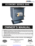
1
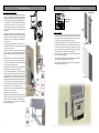
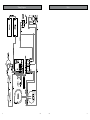
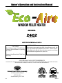
Owner’s Operation and Instruction Manual - WINDOW PELLET HEATER Window Pellet Unit MODEL 2402 PATENT NO.: 7,686,011 SAFETY TESTED TO ASTM 1509-04 & ULC S-627-00 CAUTION! Read All Instructions Carefully Before Starting The Installation or Operating This Heater. SAFETY NOTICE: If this heater is not properly installed, a house fire may result. For your safety, follow the installation instructions. Contact your local building or fire officials about obtaining a permit, restrictions and installation requirements in your area. Improper Installation Could Void Your Warranty! SAVE THIS MANUAL FOR FUTURE REFERENCE STATES ST OV TED NI USSC E U THIS MANUAL WILL HELP YOU TO OBTAIN EFFICIENT, DEPENDABLE SERVICE FROM THE HEATER, AND ENABLE YOU TO ORDER REPAIR PARTS CORRECTLY. KEEP IN A SAFE PLACE FOR FUTURE REFERENCE. COMPANY United States Stove Company 227 Industrial Park Road P.O. Box 151 South Pittsburg, TN 37380 Ussc C CM US 8520111 2 CUT HERE WARRANTY INFORMATION CARD Name__________________________________________ Telephone #: (_____)_____________ City____________________________________________ State_______ Zip_________________ Email Address __________________________________________________________________ Model # of Unit________________________________ Serial #___________________________ Fuel Type: qWood qCoal qPellet qGas qOther _________________________ Place of Purchase (Retailer)______________________________________________________ City____________________________________________ State_______ Zip_________________ If internet purchase, please list website address___________________________________ Date of Purchase _______________________________________________________________ Reason for Purchase: qDecoration qAlternative Heat qCost qMain Heat Source qOther _________________________ What was the determining factor for purchasing your new USSC appliance?_______ I have read the owner’s manual that accompanies this unit and fully understand the: Installation q Operation q and Maintenance q of my new USSC appliance. Print Name Signature Date Please attach a copy of your purchase receipt. Warranty not valid without a Proof of Purchase. Warranty information must be received within 30 days of original purchase. CUT HERE This heater must be installed in an exterior wall or window to the outside. Contact your local building officials to obtain a permit and information on any additional installation restrictions or inspection requirements in your area. Save these instructions.. This manual has important operating and maintenance instructions that you will need at a later time. Always follow the instructions in this manual. This heater is designed and approved for premium hardwood pellet fuel only. Any other type of fuel burned in this heater will void the warranty and safety listing. Never use gasoline, gasoline-type lantern fuel, kerosene, charcoal lighter fluid, or similar flammable liquids to start or “freshen up” a fire in this heater. Keep all such liquids well away from the heater while it is in use. A working smoke detector must be installed in the same room as this product. Do not unplug the heater if you suspect a malfunction. Turn the ON/OFF SWITCH to ”OFF’ and contact your dealer. Do not operate your heater with the viewing or combustion door open. The auger will not feed pellets under these circumstances and a safety concern may arise from sparks or fumes entering the room. Never disable or bypass the safety devices in this unit. Doing so could result in damage to the unit or endanger yourself or someone else. Your heater requires periodic maintenance and cleaning (see ”MAINTENANCE ”). Failure to maintain your heater may lead to improper and/or unsafe operation. Never try to repair or replace any part of the heater unless instructions for doing so are given in this manual. All other work should be done by a trained technician. Turn the heater OFF and allow to completely cool before performing any maintenance. Disconnect the power cord before performing any maintenance! NOTE: Turning the ON/OFF Switch to ”OFF” does not disconnect all power to the electrical components of the heater. Ashes must be disposed in a metal container with a tight fitting lid. The closed container of ashes should be placed on a non-combustible surface or on the ground, well away from all combustible materials, pending final disposal. The exhaust system should be checked bi- monthly during the burning season for any build-up of flyash, soot or creosote. HOT WHILE IN OPERATION. KEEP CHILDREN CLOTHING AND FURNITURE AWAY. CONTACT MAY CAUSE SKIN BURNS. Do not touch the hot surfaces of the heater. Educate all children on the dangers of a hightemperature heater. Young children should be supervised when they are in the same room as the heater. A power surge protector is required. This unit must be plugged into a 110 - 120V, 60 Hz grounded electrical outlet. Do not use an adapter plug or sever the grounding plug. Do not route the electrical cord over the heater. Do not route the cord in foot traffic areas or pinch the cord under furniture. The heater will not operate during a power outage. If a power outage does occur, check the heater for smoke spillage and open a window if any smoke spills into the room. Never block free airflow through the open vents of the unit. Keep foreign objects out of the hopper. The moving parts of this heater are propelled by high torque electric motors. Keep all body parts away from the auger while the heater is plugged into an electrical outlet. These moving parts may begin to move at any time while the heater is plugged in. Do not place clothing or other flammable items on or near this heater. WARNING—DO NOT INSTALL THIS UNIT IN A SLEEPING ROOM. CAUTION—The structural integrity of the mobile home floor, wall, and ceiling/roof must be maintained. This appliance is not intended for commercial use. DO NOT INSTALL A FLUE DAMPER IN THE EXHAUST VENTING SYSTEM OF THIS UNIT. DO NOT CONNECT THIS UNIT TO A CHIMNEY FLUE SERVING ANOTHER APPLIANCE. DO NOT USE CHEMICALS OR FLUIDS TO START THE FIRE; DO NOT BURN GARBAGE OR FLAMMABLE FLUIDS SUCH AS GASOLINE, NAPHTHA OR ENGINE OIL. Detach this page from this manual, fold in half with this page to the inside and tape together. Apply a stamp and mail to the address provided. You may use an envelope if you choose. You may register online by going to www.usstove.com All information submitted will be kept strictly confidential. Information provided will not be sold for advertising purposes. Contact information will be used solely for the purpose of product notifications. " IMPORTANT: Read this entire manual before installing and operating this product. Failure to do so may result in property damage, bodily injury, or even death. Proper installation of this heater is crucial for safe and efficient operation. Never use make-shift compromises during the installation. Before installing your heater, you must perform an initial burn in an OUTSIDE environment. Follow the Start-Up Procedure in the Operation section of this manual. " Safety Precautions Ussc Ussc 3 CUT HERE " Specifications Heating Specifications Heat Output1 1 BTU output will vary depending on the quality of fuel. Use PFI listed fuels for the best results. 2 Heating capacity will vary depending on floor plan layout of your home, degree of insulation, and the outside temperature. 3 Pellet size may effect the actual rate of fuel feed and burn times. Fuel feed rates may vary by as much as 20%. Use PFI listed fuel for best results. 16,400 BTU/hr. Heating Capacity2 500 - 1,000 sq. ft. Fuel Burn Rate ¾ - 2½ lbs./hr. Burn Time (lowest setting) approx. 35-40 hrs. Hopper Capacity approx. 30 lbs. 3 22½ [572] Dimensions Height 21⅜ in. [543mm] Width 22½ in. [572mm] Depth 27⅛ in. [689mm] Weight 126½ lbs. [57.5kg] Window / Cut-Out Dimensions Minimum Cut-out / Window Opening 14” x 22¾” inches [milimeters] [356 x 578] 24⅞ [632] 12½ [318] 12⅜ [314] Ê Fold Here Fold Here 22⅞ [581] É 21⅜ [543] 13¾ [349] Place Stamp Here 5½ [140] 4 [102] Electrical Specifications Electrical Rating 110-120 volts, 60 HZ, 3.0 Amps Watts (operational) 175 (approx.) Watts (igniter running) 425 (approx.) FUEL CONSIDERATIONS " 4 CUT HERE United States Stove Company P.O. Box 151 South Pittsburg, TN 37380 Ussc Your Pellet heater is designed to burn certified Premium Hardwood pellets that comply with Association of Pellet Fuel Industries standards. Pellets that are soft, contain excessive amounts of loose sawdust, have been, or are wet, will result in reduced performance. Failure to use proper fuel can affect the longevity of the appliance. Smaller pellets could affect feed rates. Store your pellets in a dry area and well away from the heater. SAFETY AND COMPLIANCE Pellet Fuel Institute (PFI) Premium Standards Min. Density 40 lbs. per cubic ft. Size ¼” to 5/16” diameter, length no greater than 1½” Heat Output 8,200 BTU/lb Moisture Content 8% by weight or less Ash Content 1% by weight Salt Content 300 parts per million or less Your Pellet heater has been safety tested and listed to ASTM E 1509-04 and ULC S627-00, by Intertek Testing Services in Portland, Oregon, USA. Ussc 5 Assembly Installation Your Eco-Aire heater comes pre-assembled with the exception of the Spark Suppressor that needs to be attached to the rear of the unit on the exhaust outlet. Floor protection This heater must have a non-combustible floor protector (ember protection) installed beneath it if the floor is of combustible material. If a floor pad is used, it should be UL listed or equal. The floor pad or non-combustible surface should be large enough to extend a minimum of 6-inches [152mm] in front and 2-inches [51mm] on each side of the heater. DO NOT OPERATE THIS HEATER WITH THE SPARK SUPPRESSOR REMOVED! Using the hardware and gasket supplied, attach the suppressor to the rear of the unit as shown in the illustration. Canadian Installations require a minimum of 450 mm [17.7”] beyond the front of the unit and 200mm [7.8”] beyond each side of the unit 2 [51] 2 [51] Your heater will need a minimum 18½” x 34½” floor protector. A Floor Protector of ¼ inch thick is recommended for this installation. 6 [152] Installation inches [milimeters] Read this entire manual before you install and use your Pellet heater. Failure to follow instructions may result in property damage, bodily injury, or even death! Clearances to Combustibles Before installing your heater, you must perform an initial burn in an OUTSIDE environment. Follow the Start-Up Procedure in the Operation section of this manual. 6” [152mm] Your Eco-Aire heater may be installed to code in either a conventional or mobile home (see SPECIAL MOBILE HOME REQUIREMENTS). It is recommended that only a authorized technician install your heater, preferably a National Fireplace Institute (NFI) certified specialist. 60” [1.5M] This heater must be installed through an opening on an exterior wall. The heater may be installed in an existing window or opening cut through a wooden, brick, or masonry wall. Once the desired location is selected, and before cutting a hole, check the outside of the structure for anything obstructing clearances to the exhaust vent. Also clear away leaves, shrubs/bushes, or trees that may be around the exhaust outlet. 2” [51mm] VENT TERMINATION CLEARANCES: A) Minimum 4-foot [1.2m] clearance below or beside any door or window that opens. B) Minimum 1-foot [0.3m]clearance above any door or window that opens. C) Minimum 2-foot [0.6m] clearance from any adjacent building. D) Minimum 7-foot [2.1m] clearance from any grade when adjacent to public walkways. E) Minimum 2-foot [0.6m] clearance above any grass, plants, or other combustible materials. F) Minimum 4-foot [1.2m] clearance from an forced air intake of any appliance. G) Minimum 2-foot [0.6m] clearance below eves or overhang. H)Minimum 1-foot [0.3m] clearance horizontally from combustible wall. General Installation Clearance: This unit is approved for Zero Clearance to any installed combustible surface such as the window sash, sill, or wooden structure in a wall installation. However, clearance should be considered for ease of installation and removal for maintenance and repair. Clearance Floor (Allow for brace) 6 inches [152mm] Left / Right 2 inches [51mm] Ceiling (Allow for fuel loading) 6 inches [152mm] Front 60 inches [1.5M] General Installation Notes NOTICE: This unit shall be installed in such a way that the exhaust gases are directed so they do not jeopardize people, overheat combustible structures, or enter buildings. INSTALL VENT AT CLEARANCES SPECIFIED ABOVE. IMPROPER INSTALLATION: The manufacturer will not be held responsible for damage caused by the malfunction of a heater due to improper venting or installation. Call (800) 750-2723 and/or consult a professional installer if you have any questions. 6 Combustible Ussc ♦ Do not install heater where the exhaust will terminate in a window well or any opening below ground level. ♦ Special precautions may be required to prevent snow build-up within 12 inches of the air intake. ♦ Clearances around heater must provide adequate room for service, cleaning, and air circulation. ♦ Residential Garage Installation: The heater shall be located or protected so it is not subject to damage by a moving vehicle. Use care when selecting a good location within the garage. DO NOT locate the heater where the discharge air will be directed onto a nearby parked vehicle. DO NOT store containers of paint, gasoline, or other flammable liquids in the same area as the heater, inside or outside the home or structure. Ussc 7 Window Installation When Installing your heater in a window • Select a window of adequate size and with the appropriate clearances needed for a safe installation. The mounting hardware supplied is designed for the appliance to be installed in the approximate center of the window. You will need to provide the attaching hardware, (i.e. screws, wall anchors, etc.) of which should be suitable for mounting to the outside surface of your home or structure. You may choose to utilize the supplied mounting system or a configuration of your own. However, U.S. Stove shall not be liable for faulty mounting configurations. • Depending on your application, a solid resting surface will need to be established on the window sill. If your selected window’s bottom flange rises above the sill, a board will need to be placed and should be level with or just rise above that flange. Use the illustration to the right for reference. • The supplied support brackets will need to be mounted before inserting the heater into the window. These pieces will mount to the outside of the home or structure. • Assemble the two Knee Braces to the Retention Bracket using a washer (d) and nut (e) for each side. Tighten the nuts then back them off to allow the bracket to slide back and forth along the knee braces. • Using a carpenter’s level or a straight edge, determine the height of the retention bracket in relation to the resting surface of the heater. Once you’ve determined that mark, locate the mounting assembly 1/4” lower to allow for precipitation runoff. • Attach the Knee Braces to the home or structure using the hardware that you have determined suitable for your application. • Once you’ve stabilized the Knee Braces, you’re ready to insert the heater into the window/opening. Slide the heater thru the window or opening. Insert item “a” in the center hole of the bottom but don’t tighten fully. Allow item “a” to engage the SLOT in the retention bracket as shown in the illustration to the right. Slide the heater into the window opening until it stops. The heater should either stop on the window sash at the back of the hopper lid or on the window sill when it reaches the fan enclosure, whichever comes first. • Align the holes in the retention bracket and heater bottom. Insert a washer (b) and bolt (c), and tighten. • Tighten the two nuts (e) on the knee braces. • Using the window sill brackets, mount them to the side of the heater, using the existing cabinet screws, then to the top of the window sill with the screws provided. See illustration on the following page. • Lower the sash onto the top of the heater and proceed to install the window insulation/filler panels. Window Installation TWO-SIDED TAPE WINDOW Sill MOUNTING BRACKETS A B SCREW SLOT Retention Bracket Installing the filler panels • Begin by assembling the left and right side filler panels together. Slide part A into part B; Notice the range of adjustment. If the openings on each side of the heater exceeds this range, you will have to fill the gap by other means necessary to keep the window/opening weather tight. Otherwise, proceed. • Place the panel assembly against the bottom of the window sash and bottom of the window frame. Slide apart the two sections until the flange on part A meets the inside of the window frame and the flange on part B meets the side of the heater. Using a drill with a 5/16” socket bit, drive the self-tapping screw through the hole in part A into part B. This sets the width of the panels. • Peel away the protective coating from the two-sided tape on the flanges and adhere it to the window and framing. • Measure the filler panel width and cut the foam insulation to size. Peel away the coating on the tape strips and apply the foam to the panels. • Finish the install by sealing around the outside of the heater and filler panels with a weatherproofing silicone sealant. TWO-SIDED TAPE CUT-TO-FIT a b Knee Braces c d e 8 Ussc Ussc 9 Understanding your heater Wall Installation When Installing your heater in an exterior wall • Select a wall to the exterior of the building. This wall should have the required clearance to combustibles inside and out mentioned earlier in this manual. Make certain that electrical wires, conduit, water or gas pipes do not pass through the area you have selected • USSC suggest the following installation illustrated to the right, however, you may frame the hole cut out to your discretion. A sturdy base for the heater to rest should be established. • At the desired height, mark the hole location for your heater. Measure and cut the appropriate size hole for your installation. The cut out should border a wall stud. The next wall stud will need to be cut. How your heater works [648mm] [356mm] [432mm] [572mm] Your Eco-Aire pellet heater operates on a timer based auger fuel feed system, that is controlled by a digital circuit board. The fuel is delivered from the auger into a burn pot, which is the vessel where the combustion process takes place. Based upon the heat ranges (1-5), the heater will feed the appropriate amount of fuel to reach a set temperature range. Note that the amount of heat produced by the heater is proportional to the rate of the fuel that is burned. Your heater is equipped with an automatic ignition system that should ignite the fuel within 5-10 minutes from pressing the ON button. As pellets fall into the burn pot and ignite, outside air is drawn in to feed the fire by a combustion blower. The post combustion gases are then pulled through the heat exchanger as they are traveling out the exhaust. As the heater warms up, room air is circulated around the heat exchanger by means of a room air blower, distributing warm air into the room. Because a forced draft pressure is required for the combustion process inside your heater, it is extremely important that the exhaust system be properly maintained. And, that when operating your heater, you make sure that the viewing and combustion doors are properly closed and/or sealed. Build a frame of 2 x 4’s at the dimensions suggested and secure it in place by attaching it to the available studs. • Before installing the heater, install the Knee/Support Braces. • Install the knee/support braces supplied. See the previous page for installation. You may use the hardware supplied or purchase the appropriate fasteners from your local hardware store for the type of material you are securing into. Control Panel Overview • Seal around the heater with silicone or caulking to protect against the weather. Turning the heater ON/OFF, as well as adjustments for the fuel feed rate is performed by pressing the appropriate button(s) on the control panel which is located on the front, lower left-hand corner of your heater. ON/OFF • Pressing the “ON” button on the control panel will begin the start-up sequence for the heater. Fuel will begin to feed through the auger feed system then ignite after approx. 5 minutes. • Pressing the “OFF” button on the control panel will cause the heater to enter its shut-down sequence. The fuel feed system will stop pulling fuel from the hopper and, once the fire goes out and the heater cools down, the fans will stop running. HEAT RANGE • Pressing the “Heat Range” arrows, up or down, will adjust the amount of fuel being delivered to the burn pot. • The exhaust blower will start. Note that this appliance pulses the exhaust blower in order to achieve the proper air to fuel ratio, and to also aid in the cleaning of the burn pot. • Once the heater reaches a set temperature, the room fan will come on. Mobile Home Installation Requirements LIGHT (LED) INDICATORS WARNING! - Do not install in a sleeping room CAUTION! - The structural integrity of the mobile home floor, wall, and ceiling/roof must be maintained. • The heater must be permanently attached to the wall. • The heater must be electrically grounded to the steel chassis of the mobile home with 8 GA copper wire using a serrated or star washer to penetrate paint or protective coating to ensure grounding. • When moving your mobile home, the heater must be removed while the mobile home is being relocated. After relocation, heater may be reinstalled and securely fastened. • Check with your local building officials as other codes may apply. 10 • Heat Range LED - displays the selected heat setting. Number “1” LED lights to display that there is power to unit even if the heater is off. • Door Sw LED - lights when front viewing door is opened or if the hopper lid is raised. • Press Sw LED - lights if pressure is lost inside the combustion chamber. (See “Errors”) • E LED - Operational Error (See “Errors”) • ON LED - Flashes in start-up mode. On solid during Run mode • OFF LED - Flashes during shut down mode Ussc Ussc 11 Operation Operation DAILY OPERATION UNIT PREPARATION After properly installing your heater, you will need to perform the following steps before operation: • Attach the electrical cord to the left side blower housing first; then plug it into a 110-volt outlet (an outlet surge protector is highly recommended). PERFORMING AN INITIAL BURN You must perform an initial burn in this appliance before installing it in your home or garage. This process is to ensure that the appliances is functioning correctly, to cure the high temperature paint and burn off any oil that is present in the sheetmetal components of the combustion chamber. For the initial burn, only add a small amount of fuel, approximately 4-5 lbs. or about the amount to fill a 2 lb. coffee can. Operate the appliance on the 3 or 4 heat setting for approximately 30 minutes to an hour. There will probably be a small amount of smoke or fumes irradiating from the appliance during this process. Follow the Start-Up procedure below to begin your burn. START-UP PROCEDURE Never use gasoline, gasoline-type lantern fuel, kerosene, charcoal lighter fluid, or similar liquids to start or “freshen up” a fire in this heater. Keep all such liquids well away from the heater while it is in use. 1. Verify that the hopper is clean and free of foreign matter. 2. Fill the hopper with wood pellets; do not allow any part of the bag or any other foreign material into the hopper, as this may jam the auger. 3. Ensure that all pellet matter is cleared from the hopper seating surface. Never place your hand near the auger while the heater is in operation. This unit should be filled when the hopper level drops below 3-inches. In the event of a power outage, the heater will not function. If the unit was “ON” when the power outage occurred, one of the following will take place: 1.) If the heater is still warm, it will resume feeding fuel and continue to operate normally. If the fire has gone out, you will have to press the “OFF” button and then the “ON” button again to begin a new start-up sequence. 2.) If the heater has cooled-off, it will reset to its “OFF” condition. At this point, you may press the “ON” button and the unit will begin a new start-up sequence. Make it a habit to empty the burn pot in these situations. NOTE: The unit will also shut down in the event of an exhaust blower failure; if this is the case, the unit will not re-start and you must contact Customer Service at (800) 750-2723. safety and Convenience features Your Eco-Aire incorporates safety switches that helps ensure that everything is in proper working order before feeding fuel to the burn pot. The heater will not operate if the viewing or combustion door is left open; or if the exhaust blower fails or the exhaust system is blocked. The RTD, Resistance Temperature Device, will prevent your heater from operating at abnormally high temperatures. The heater has two over temperature limits. If the unit reaches the first limit, it will reduce fuel consumption in order to reduce temperatures. If the unit reaches the second limit, it will shut down and will need to be restarted. Your heater also includes an auto-start igniter as a standard feature. The use of other fire starter materials (wood chips, starter gel, etc.) is not necessary. By simply pressing the “ON” button on the digital control panel, your heater will begin to feed fuel and automatically start within 5 minutes. 4. Close the hopper lid. The unit WILL NOT feed fuel with the hopper lid open. 5. Verify that there is no pellet fuel, ash, or foreign matter in the burn-pot before starting the appliance. 6. Make sure that the viewing door and combustion door is securely closed (the safety switch will not allow the heater to feed fuel if they are left open. 7. Press the “ON” button on the control pad and set the “heat RANGE” to your desired setting. The ON light will be flashing and the light corresponding with the heat setting will be light. What will happen next.... The heater will begin to feed fuel and the exhaust (draft) blower is running. Note that the exhaust blower is pulsing. The auto-start ignitor will ignite the fuel in approximately 5-10 minutes. In the start-up mode, the “ON” LED will flash until it reaches a factory preset temperature. At that point, the “ON” LED will come on solid and the heater will begin to ramp up to your selected heat range. Maintenance Failure to clean and maintain this unit as indicated can result in poor performance, safety hazards and void your warranty. Unplug your heater’s electrical cord prior to removing the back panel or opening the exhaust system for any inspection, cleaning, or maintenance work. Never perform any inspections, cleaning, or maintenance on a hot heater. Do not operate heater with broken glass , leakage of flue gas may result. The Room Air Blower will not function until the heater reaches a factory preset temperature. Exhaust System SHUT DOWN PROCEDURE The by products of combustion contain small particles of fly ash. Fly ash will collect in the exhaust venting system and restrict the flow of flue gases. Incomplete combustion, such as during startup, shutdown, or incorrect operation of the heater will lead to soot or creosote formation which will collect in the exhaust system and if ignited, an extremely hot fire could result. Therefore, it is important that the exhaust system be inspected and cleaned at least bi-monthly during the burning season. Contact your local municipal or provincial fire authority for information on how to handle a fire. Have a clearly understood plan to handle a fire if one should ever occur. Cleaning or monitoring the areas behind the front cleanout door should be done frequently to ensure minimum fly ash or soot/creosote build-up. Occasionally remove the spark suppressor from the rear of the heater and clean thoroughly with soapy water. Before reinstallation, ensure that the suppressor is completely dry. If moisture is present inside the suppressor, accumulation of fly ash will be greater and will require cleaning more frequently. Press the “OFF” button on the control pad to put the stove in shut down mode. At this time, the red light above the OFF will blink and the “ON” light will go off. The auger will stop feeding pellets, but the distribution blower and exhaust blower will continue to operate. When the internal temperature of the unit drops below the factory preset temperature, the distribution blower and exhaust WARNING: Never shut down this unit by unplugging it from the power source. blower will cease to operate. The red light will then shut off and the unit will be completely shut down. The hotter the unit is during its operation, the longer it will take for the stove to complete the shut down cycle. If the stove stays on for more than 1 hour after pressing the “OFF” button and you are sure that the fire is out, the stove can be unplugged from the outlet. After approximately 10 seconds, the unit can be re-connected to the power source and the control board will be reset. Interior Chambers Periodically remove and clean the burn pot and the areas behind the cleanout door. In particular, it is advisable to clean out the holes in the burn pot to remove any build up that may prevent air from moving through the burn pot freely. As good practice, you should remove and clean the burn pot each time you restart the heater as this ensures that the best efficiency is achieved. If a vacuum is used to clean your heater, we suggest using a vacuum designed for ash removal. Some regular vacuum cleaner (i.e. shop vacs) may leak ash into the room. 12 Ussc Ussc 13 Maintenance Trouble Shooting Errors Ash Disposal Ashes should be placed in a metal container with a tight fitting lid. The closed container of ashes should be placed on a noncombustible floor or on the ground, well away from all combustible materials, pending final disposal. If the ashes are disposed of by burial in soil or otherwise locally dispersed, they should be retained in the closed container until all cinders have been thoroughly cooled. Do not place other waste in the same container. Check and Clean the Hopper Check the hopper periodically to determine if there is any sawdust or pellets that are sticking to the hopper surface. Clean as needed. Door and glass Gaskets Inspect the door’s and ash pan’s gaskets periodically. These may need to be removed to have frayed, broken, or compacted gaskets replaced. Keep door, glass, and ash pan seals in good condition. Disconnect the power cord before performing any maintenance! NOTE: Switching the appliance to ”OFF” does not disconnect all power to the electrical components of the heater. Never try to repair or replace any part of the heater unless instructions for doing so are given in this manual or supplied from the factory. All other work should be done by a trained technician. PROBLEM CAUSE: To rich air/fuel mixture Orange, lazy flame, excessive fuel build-up • Clean out the burn pot and behind the cleanout door. in the burn pot • Make sure that the combustion door is closed and sealed properly. If not, adjust door catch and/or replace door gaskets. • Check that the exhaust is clear of any obstructions. Clean as needed Blower Motors • Check for proper seating of the burn pot. Clean the air holes on the motors of both the exhaust and distribution blowers annually. Remove the exhaust blower from the exhaust duct and clean out the internal fan blades as part of your fall start-up. PROBLEM CAUSE: Burn pot burns out of fuel Painted Surfaces Fire goes out or heater shuts down. • Hopper is empty, refill the hopper. • Loss of draft pressure. Make sure that the combustion door is closed and sealed properly. If not, adjust door catch and/or replace door gaskets. Check that the exhaust is clear of any obstructions. Clean as needed. Painted surfaces may be wiped down with a damp cloth. If scratches appear, or you wish to renew your paint, contact your Authorized Eco-Aire Dealer to obtain a can of suitable high-temperature paint. GLASS • Make sure the viewing door and hopper lid is closed completely. Cleaning - We recommend using a high quality glass cleaner. Should a build up of creosote or carbon accumulate, you may wish to use 000 steel wool and water to clean the glass. DO NOT use abrasive cleaners. DO NOT perform the cleaning while the glass is HOT. , In the event you need to replace the glass, follow these instructions. Wear leather gloves or any other gloves suitable for handling broken glass. Dispose of all broken glass properly. Use ONLY high temperature ceramic glass of the correct size and thickness. DO NOT substitute alternative materials for the glass. Contact your authorized dealer to obtain this glass. For the glass in the front door, bend the two tabs up and remove any broken or frayed glass. Replace the glass and bend the tabs back down. For the Fire Door Glass, remove the retainers and any broken glass or silicone residue from the sealing face of the door. Before replacing the glass, apply a small bead (about 1/8” wide) of High Temperature Silicone around the inside face of where the glass will sit, approximately 1/4” from the edge of the opening on the sheetmetal door. Insert the new glass, allowing it to press the silicone flat. Re-install the retainers to hold the glass. Be careful not to overtighten the screws for this could damage the glass. • Auger system is jammed or there is a “bridging” of the fuel in the hopper, preventing fuel from flowing into the auger feed system. PROBLEM CAUSE: Auto-Start Igniter fails to ignite the fuel in the burn pot. Heater does not start a fire when the “ON” • Turn the heater “OFF”. Clear the un-burnt fuel from the burn pot and try again. button is pushed • Check the pellet quality. Replace if moist, wet, or dirty. • Loss of draft pressure. Make sure that the combustion door is closed and sealed properly. If not, adjust door catch and/or replace door gaskets. Check that the exhaust is clear of any obstructions. Clean as needed. DO NOT abuse the door glass by striking, slamming or similar trauma. Do not operate the stove with the glass removed, cracked or broken. • Check that the auto-start igniter is not blocked with ash or soot. (The igniter is located behind the burn pot on the back wall of the combustion chamber.) FALL START UP Prior to starting the first fire of the heating season, check the outside area around the exhaust and air intake systems for obstructions including leaves, bushes/shrubs, and/or trees. Clean and remove any fly ash from the exhaust venting system. Clean any screens on the exhaust system and on the outside air intake pipe. Turn all of the controls on and make sure that they are working properly. This is also a good time to give the entire heater a good cleaning throughout. • The auto-start igniter gets “red hot” during start-up. If you can not visibly see the igniter glowing during start-up, then the igniter may need to be replaced or there is a problem with the electrical control system. • Check for proper alignment between the burn pot and the igniter tube. SPRING SHUTDOWN After the last burn in the spring, remove any remaining pellets from the hopper and the auger feed system. Scoop out the pellets and then run the auger until the hopper is empty and pellets stop flowing. Vacuum out the hopper. Thoroughly clean the burn pot, and firebox. The exhaust system should be thoroughly cleaned. If removing the unit for storage, store the heater in a dry location. YEARLY SERVICING A yearly servicing and cleaning by your Authorized Eco-Aire Dealer is recommended. A fee may be charged for this service. PROBLEM CAUSE: Heater has reached the 2nd over temperature limit. Heater enters shut-down mode • To much fuel in the burn pot. Restart heater after heater has cooled. • RTD sensor in the room discharge air may be faulty causing the room fan not to come on. Contact your dealer. 14 Ussc Ussc 15 Parts Diagram Parts List 2402 40 39 43 42 39 41 LEFT SIDE RIGHT SIDE FILLER PANELS 16 FOAM INSULATOR PANEL CUT-TO-SIZE Ussc Ussc Item Part No. Title Qty. 1 2 3 4 N/S 5 6 7 8 9 10 11 12 13 14 N/S 15 16 17 18 19 20 21 22 23 24 N/S N/S N/S 25 26 27 28 29 30 31 32 33 34 35 36 37 38 39 40 41 42 43 88033 891544 891951 83339 83261 88144 891952 891542 80573 88129 891702 80531 80529 891747 891132 83534 83529 80543 86615 891589 80549 891121 89586 80545 80555 80550 80544 80559 80551 80546 80542 80462 80557 891588 891534 891532 891541 892167 891535 891545 891742 891956 891955 891959 891958 891957 83343 891960 3/8” Rope Gasket Glass, Combustion Chamber Latch, Door 1/4-20 Bolt 1/4-20 Lock Nut Gasket, Cleanout Draw Latch Latch, Push-to-Close/Microswicth Blower, Exhaust - 70CFM Gasket, Exhaust Blower Suppressor, Spark Resistance Temp. Detector (RTD) Motor, Auger Assy., Auger Bushing (Includes item 14) Agitator Bushing Bushing Retainer Ring Hairpin Ignitor Cartridge 2” ID x 18” Flex MTL Hose Cover, Intake Switch, Pressure Hose, Silicone Nipple, Auger Controller Board Assy. PWA, Display Board Keypad, Assembly Wiring Harness, Main Wiring Harness, Switches Wiring Harness, Display Interface Proximity Switch Room Blower 125CFM Receptacle, 3 Prong Power Supply Cord Burn Pot Hopper Top, Cabinet Slide Latch Front Louver Front Glass, Front Viewing Support Bracket (Window Sill) Weldment, Knee/Support Brace Retention Bracket Filler Panel, Slide Filler Panel, Left Filler Panel, Right #10 x 1/2” Self-Drilling Screw Foam, Corrugated 7/8” 3 FT 1 1 1 1 1 2 1 1 1 1 2 1 1 1 1 1 1 1 1 1 1 FT 1 1 1 1 1 1 1 1 1 1 1 1 1 1 1 1 1 1 2 2 1 2 1 1 2 1 17 Wiring Diagram 18 Notes Ussc Ussc 19 How to order repair parts This manual will help you obtain efficient, dependable service from your Eco-Aire, and enable you to order repair parts correctly. Keep this manual in a safe place for future reference. When writing, always give the full model number which is on the nameplate attached to the heater. When ordering repair parts, always give the following information as shown in this list: 1. The part number 2. The part description 3. The model number: 2402 STATES ST OV TED I N USSC COMPANY 20 E U 4. The serial number:____________________ United States Stove Company 227 Industrial Park Road P.O. Box 151 South Pittsburg, TN 37380 (800) 750-2723 WWW.USSTOVE.COM Ussc