1
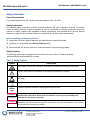
EOS-6000 Series
Optical A/B Switch
User Manual – DC Version
For more information on this and other products:
Contact Sales at EMCORE 626-293-3400, or visit www.emcore.com.
EOS 6000 Optical A/B Switch
USER MANUAL | SEPTEMBER 9, 2008
Table of Contents
Table of Contents ....................................................................................................................................2
Safety Information....................................................................................................................................3
Power Requirements ........................................................................................................................3
Safety Instructions............................................................................................................................3
Before Initializing and Operating the Unit .........................................................................................3
Safety Symbols ................................................................................................................................3
Getting Started.........................................................................................................................................4
Before Initializing and Operating the Unit.........................................................................................4
Note: Keep the packaging. ...............................................................................................................4
Optical Switch Outline Drawing (Units in mm)..................................................................................7
Operating Environment............................................................................................................................9
Temperature.....................................................................................................................................9
Humidity ...........................................................................................................................................9
Introduction ..............................................................................................................................................9
Front Panel View ...................................................................................................................................10
Rear Panel View (DC) ...........................................................................................................................10
Sample Application ................................................................................................................................11
Functionality...........................................................................................................................................11
Network management ....................................................................................................................11
Output Indication ............................................................................................................................11
Operation........................................................................................................................................12
Manual Switch ................................................................................................................................12
Normal Operating Condition...........................................................................................................12
Applicable Standards Compliance.........................................................................................................13
EMI/EMC ........................................................................................................................................13
Packaging ..............................................................................................................................................13
Packaging.......................................................................................................................................13
2 of 14
EMCORE Broadband
2015 West Chestnut Street
Alhambra, California 91803-1542
Tel: 626-293-3400
Fax: 626-293-3428
Copyright 2008. EMCORE Corporation
EOS 6000 Optical A/B Switch
USER MANUAL | SEPTEMBER 9, 2008
Safety Information
Power Requirements
The system operates from a DC power source that supplies -36 to -60 V DC.
Safety Instructions
The following safety instructions must be observed whenever the unit is operated, serviced, or repaired.
Failure to comply with any of these instructions or with any precaution or warning contained in the user’s
manual is in direct violation of the standards of design, manufacture, and intended use of the unit. Emcore
assumes no liability for the customer’s failure to comply with any of these safety requirements.
Before Initializing and Operating the Unit
Inspect the unit for any signs of damage, and read the user’s manual thoroughly.
Install the unit as specified in the Getting Started section.
Ensure that the unit and any devices or cords connected to it are properly grounded.
Safety Symbols
The following symbols and messages can be marked on the unit (Table 1). Observe all safety
instructions that are associated with a symbol.
Table 1: Safety Symbols
Symbol
Description
Laser safety. See the user’s manual for instructions on handling and operating the unit safely.
See the user’s manual for instructions on handling and operating the unit safely.
Electrostatic discharge (ESD). See the user’s manual for instructions on handling and operating the
unit safely.
Frame or chassis terminal for electrical grounding within the unit.
Protective conductor terminal for electrical grounding to the earth.
WARNING
The procedure can result in serious injury or loss of life if not carried out in proper compliance
with all safety instructions. Ensure that all conditions necessary for safe handling and
operation are met before proceeding.
CAUTION
The procedure can result in serious damage to or destruction of the unit if not carried out in
compliance with all instructions for proper use. Ensure that all conditions necessary for safe handling
and operation are met before proceeding.
3 of 14
EMCORE Broadband
2015 West Chestnut Street
Alhambra, California 91803-1542
Tel: 626-293-3400
Fax: 626-293-3428
Copyright 2008. EMCORE Corporation
EOS 6000 Optical A/B Switch
USER MANUAL | SEPTEMBER 9, 2008
Getting Started
Before Initializing and Operating the Unit
1.
2.
3.
4.
Inspect the optical switch for any signs of damage, and read the User’s Manual thoroughly.
Install the optical switch as specified in the Getting Started section.
Ensure that the optical switch and any devices or cords connected to it are properly grounded.
Become familiar with all safety symbols and instructions to ensure that the optical switch is operated
and maintained safely.
Initial Inspection
WARNING
WARNING: To avoid electrical shock, do not initialize or operate the unit if it bears any sign of
damage to any portion of its exterior surface, such as the outer cover or panels.
Check that the unit and contents are complete:
1. Wear an anti-static wrist strap and work in an electrostatic discharge (ESD) controlled area.
2. Inspect the shipping container for any indication of excessive shock to the contents, and inspect the
contents to ensure that the shipment is complete.
3. Inspect the unit for structural damage that can have occurred during shipping.
Note: Keep the packaging.
Immediately inform Emcore and, if necessary, the carrier if the contents of the shipment are incomplete, if
the unit or any of its components are damaged or defective, or if the unit does not pass the initial
inspection.
4 of 14
EMCORE Broadband
2015 West Chestnut Street
Alhambra, California 91803-1542
Tel: 626-293-3400
Fax: 626-293-3428
Copyright 2008. EMCORE Corporation
EOS 6000 Optical A/B Switch
USER MANUAL | SEPTEMBER 9, 2008
Storing and Shipping
To maintain optimum operating reliability, do not store the unit in locations where the temperature falls
below -25°C or rises above 65°C. Avoid any environmental condition that can result in internal
condensation. Ensure that these temperature and humidity requirements can also be met whenever the
unit is shipped.
Claims and Repackaging
Immediately inform Emcore and, if necessary, the carrier, if
•The contents of the shipment are incomplete
•The unit or any of its components are damaged or defective
•The unit does not pass the initial inspection
In the event of carrier responsibility, Emcore will allow for the repair or replacement of the unit while a
claim against the carrier is being processed.
Returning Shipments to Emcore
Emcore will only accept returns for which an approved Return Material Authorization (RMA) has been
issued. This number must be obtained prior to shipping any material to Emcore. The owner’s name and
address, the model number and full serial number of the unit, the RMA number, and an itemized
statement of claimed defects must be included with the return material.
Ship the return material in the original shipping container and packing material. If these are not available,
typical packaging guidelines are as follows:
1. Wear an anti-static wrist strap and work in an ESD controlled area.
2. Wrap the unit in anti-static packaging. Use anti-static connector covers, as applicable.
3. Pack the unit in a reliable shipping container.
4. Use enough shock-absorbing material (10 to 15 cm or 4 to 6 in on all sides) to cushion the unit and
prevent it from moving inside the container. Pink poly anti-static foam is recommended.
5. Seal the shipping container securely.
6. Clearly mark FRAGILE on its surface.
7. Always provide the model and serial number of the unit and, if necessary, the RMA number on any
accompanying documentation.
8. Please contact the RMA department, using the contact information at the beginning of this document,
to provide an RMA number and a shipping address.
Unpacking
1. Inspect the shipping boxes for any obvious damage.
2. Unpack the unit from all packaging boxes.
5 of 14
EMCORE Broadband
2015 West Chestnut Street
Alhambra, California 91803-1542
Tel: 626-293-3400
Fax: 626-293-3428
Copyright 2008. EMCORE Corporation
EOS 6000 Optical A/B Switch
USER MANUAL | SEPTEMBER 9, 2008
3. Inspect the appearance of the unit for any shipping damage.
4. In case of damage, document and inform the shipping company and your local representative.
5. Save the shipping boxes and their inserts for any future reshipment for upgrade or repair.
NOTE: In the event of a reshipment back to the manufacturer, any additional damage caused by not using the
original boxes will be considered the responsibility of the customer.
Optical Switch Mounting and Power Connection
1. Mount the unit into a 19-inch wide rack or cabinet.
2. Turn the unit power supply switch located on the rear panel off.
3. Connect wires DC+, DC-, and GND to the pluggable terminal block that is connected to the
DC input of the power supply. The DC power source must be 36 – 60VDC and wires used
must handle at least 10VA.
4. Turn the unit power switch to the ON position.
6 of 14
EMCORE Broadband
2015 West Chestnut Street
Alhambra, California 91803-1542
Tel: 626-293-3400
Fax: 626-293-3428
Copyright 2008. EMCORE Corporation
EOS 6000 Optical A/B Switch
USER MANUAL | SEPTEMBER 9, 2008
Optical Switch Outline Drawing (Units in mm)
7 of 14
EMCORE Broadband
2015 West Chestnut Street
Alhambra, California 91803-1542
Tel: 626-293-3400
Fax: 626-293-3428
Copyright 2008. EMCORE Corporation
EOS 6000 Optical A/B Switch
USER MANUAL | SEPTEMBER 9, 2008
Operating the Optical Switch
WARNING
To avoid the risk of injury or death, always observe the following precautions before initializing the optical
switch.
If using a voltage-reducing autotransformer to power the optical switch, ensure that the common
terminal connects to the earthed pole of the power source.
Use only the type of power cord supplied with the optical switch.
Connect the power cord only to a power electrical outlet equipped with a protective earth contact.
Never connect to an extension cord that is not equipped with this feature.
Willfully interrupting the protective earth connection is prohibited.
Never look into the end of an optical cable connected to an optical output device that is operating.
Laser radiation is invisible, and direct exposure can severely injure the human eye. For more
information, see the User’s Manual of the laser source in use.
Turning off the power to the optical switch does not block the externally supplied radiation to the input
of the optical switch, or the output of the optical switch.
Do not use the optical switch outdoors.
To prevent potential fire or shock hazard, do not expose the optical switch to any source of excessive
moisture.
Do not operate the optical switch when its covers or panels have been removed.
Do not interrupt the protective earth grounding. Any such action can lead to a potential shock hazard
that can result in serious personal injury.
Do not operate the optical switch if an interruption to the protective grounding is suspected. In this
case, ensure that the optical switch remains inoperative.
Unless absolutely necessary, do not attempt to adjust or perform any maintenance or repair procedure
when the unit is opened and connected to a power source.
Repairs are to be carried out only by a qualified professional.
Do not attempt any adjustment, maintenance, or repair procedure to the optical switch’s internal
mechanism.
Disconnect the power cord from the unit before adding or removing any components.
Operating the unit in the presence of flammable gases or fumes is extremely hazardous.
Do not perform any operating or maintenance procedure that is not described in the User’s Manual.
Some of the optical switch’s capacitors can be charged even when the unit is not connected to the
power source.
8 of 14
EMCORE Broadband
2015 West Chestnut Street
Alhambra, California 91803-1542
Tel: 626-293-3400
Fax: 626-293-3428
Copyright 2008. EMCORE Corporation
EOS 6000 Optical A/B Switch
USER MANUAL | SEPTEMBER 9, 2008
Operating Environment
In order for the optical switch to meet the warranted specifications, the operating environment must meet the
following conditions for temperature and humidity.
WARNING
1. Do not use the optical switch outdoors.
2. To prevent potential fire or shock hazard, do not expose the optical switch to any source of excessive
moisture.
Temperature
The optical switch can be operated in the temperature range of 0°C to 50°C.
Humidity
The optical switch can be operated in environments with up to 85% humidity, non-condensing (0°C to 50 °C).
Do not expose it to any environmental conditions or changes to environmental conditions that can cause
condensation to form inside the optical switch.
Introduction
The Model EOS-6000 Optical A/B Switch series product line is a high performance solution for network
protection and optical redundancy. Packaged in a convenient 1RU housing, this line of optical switches
provides an automatic or manual fiber switching function to protect the network from inadvertent service
outages due to up-stream optical signal degradation. Each fiber’s optical signal power level is
continuously monitored, as is an adjustable optical trip threshold for each channel. If the primary fiber’s
optical signal power level falls below the desired optical trip threshold, the unit automatically switches to
the secondary fiber, thus eliminating the need for intervention of a system operator. The EOS-6000 is
capable of manual switching or can be switched remotely via SNMP adding optical protection to many
system applications.
9 of 14
EMCORE Broadband
2015 West Chestnut Street
Alhambra, California 91803-1542
Tel: 626-293-3400
Fax: 626-293-3428
Copyright 2008. EMCORE Corporation
EOS 6000 Optical A/B Switch
USER MANUAL | SEPTEMBER 9, 2008
Front Panel View
Power
Indicator
Main Input
Status
Backup Input
Status
Output
status
Manual switch
Rear Panel View (DC)
Main Line Backup Line
Input
Input
Output
RS232 Port for management
Com Port Select Switch
RJ45 Port for management
DC Terminal Block
Power Switch
10 of 14
EMCORE Broadband
2015 West Chestnut Street
Alhambra, California 91803-1542
Tel: 626-293-3400
Fax: 626-293-3428
Copyright 2008. EMCORE Corporation
EOS 6000 Optical A/B Switch
USER MANUAL | SEPTEMBER 9, 2008
Sample Application
The diagram below shows a typical CATV application that allows fully redundant transmitters and fiber paths,
with automatic protection to the network via the EOS-6000 switch. Contact your Emcore sales representative
for more information on Emcore’s complementary product lines.
Functionality
Network management
The EOS-6000 supports SNMP1.0 protocol for remote network management. In addition to SNMP, the
EOS-6000 also supports web browser, telnet and remote firmware upgrade.
EOS-6000 supports the following Network Management functions.
1) Monitoring the main and backup channel’s optical power;
2) Obtaining the output status;
3) Switching between the main line and the backup line
4) Setting up the following parameters:
Parameters
Switching
Threshold
Pre-alarm
dB value
Operating
mode
Description
Power value for auto-switch
The Pre-alarm power value (dBm) (for warning) =
Switching Threshold + Pre-alarm dB value
Mode 0: Switch remains on the backup line even if
the power of the main line returns to normal.
Mode 1: Switches to the main line when the power of
the main line rises above the Pre-alarm power value
(dBm).
See the “EOS-6000 Network Management Manual” for more information.
Output Indication
1) A blinking LED on either the main line or backup line indicates the current working channel.
2) If the working channel’s optic power is:
11 of 14
EMCORE Broadband
2015 West Chestnut Street
Alhambra, California 91803-1542
Tel: 626-293-3400
Fax: 626-293-3428
Copyright 2008. EMCORE Corporation
EOS 6000 Optical A/B Switch
USER MANUAL | SEPTEMBER 9, 2008
a. Above the Pre-alarm power value (dBm), the output indicator is green;
b. Above the Switching Threshold but below the Pre-alarm power value (dBm), the output
indicator is yellow;
c. Below the Switching Threshold, the output indicator is red.
3) If the optic power of either the main line or backup line is higher than the Switching Threshold,
the output indicator is green, otherwise red.
Operation
1) If the working channel is on the main line currently, it will not switch to the backup line until the main
line’s optic power drops below the switching threshold and the backup line’s optic power is higher than
the switching threshold.
2) If the working channel is on the backup line currently,
a. For “mode 0”, it will not switch to the main line until the backup line’s optic power drops below the
switching threshold and the main line’s optic power is higher than the switching threshold.
b. For “mode 1”, it will switch to the main line at once when the main line’s optic power rises above the
Pre-alarm power value (dBm).
Manual Switch
The manual switch is enabled and will take effect only when the optic powers of two channels are both
either above or below the switching threshold in mode 0 or below the switching threshold in mode 1.
Normal Operating Condition
The normal operating condition is when the unit is powered on, receiving optical power on both its main
and backup working channels with optical powers above the pre-alarm power values. The optical switch
is positioned to passively direct the main optical power to the output port. In this case, the front panel
LED indicators, “Power”, “Main”, and “Output” are steady green, and “Backup” is blinking green.
Optical Characteristics
TYP.
MAX.
nm
Insertion Loss
dB
Return Loss
dB
Polarization Dependent
Loss
Repeatability
dB
0.06
0.1
dB
+/-0.01
+/-0.02
Isolation
dB
-60
-50
Input Optical Power
Switching Time
UNITS
MIN.
PROPERTY
Operating Wave Length
1310 +/- 10 or 1550+/-20
1.0
55
1.3
60
dBm
24
ms
25
General and Mechanical Specifications
PROPERTY
Switching Threshold
Switching Mode
REQUIREMENT
20 dB range – see datasheet
Auto, Manual, remote
COMMENTS
Settable within range
12 of 14
EMCORE Broadband
2015 West Chestnut Street
Alhambra, California 91803-1542
Tel: 626-293-3400
Fax: 626-293-3428
Copyright 2008. EMCORE Corporation
EOS 6000 Optical A/B Switch
Optical Connector
Monitoring Interfaces
USER MANUAL | SEPTEMBER 9, 2008
Operating Temperature
SC/APC
100 Base-T Ethernet
Rear Panel RS-232 interface
LED Indicators
0°C to 50°C
Storage Temperature
Power Consumption
-25°C to 65°C
5W
Supply Range
(VDC)
Dimensions
Other styles available
SNMP V1
Reserved for Factory Use
Power, Main, Backup, and Output Indicators
Maximum
36 - 60 VDC
430x300x44mm
Applicable Standards Compliance
EMI/EMC
EN55022:2006 conducted emissions, information technology equipment
EN55022:2006 radiated emissions, information technology equipment
EN55024: 1998/A1:2000/A2: 2002
IEC 61000-4-2: 2001
IEC 61000-4-3:2008
IEC 61000-4-4:2004
IEC 61000-4-6:2006
FCC Part 15 (CFR 47), subpart B, Class B
Packaging
Packaging
The module shall be sealed in an anti-static bag.
The product manual will be installed in an anti-static bag and shipped with the unit
MIB’s and manuals will be provided on a CD-ROM supplied with unit
13 of 14
EMCORE Broadband
2015 West Chestnut Street
Alhambra, California 91803-1542
Tel: 626-293-3400
Fax: 626-293-3428
Copyright 2008. EMCORE Corporation
EOS 6000 Optical A/B Switch
USER MANUAL | SEPTEMBER 9, 2008
Laser Safety
Class 1 Device
This equipment is inherently classified as a Class I laser product, since the equipment contains no laser or
light emitting diode (LED) of a higher class number.
WARNING
Although unit is classified as a Class 1 device, a hazard can exist due to laser radiation emitting from
the output port of the optical switch, and thus eye safety precautions should be adhered to at all times.
Never look into an uncovered optical bulkhead connector or the end of an optical cable connected to
an optical output device that is operating. Laser radiation is invisible, and direct exposure can severely
injure the human eye. For more information, see the User’s Manual of the laser source in use.
Turning off the power to the optical switch does not block the externally supplied radiation to the input
of the optical switch, or the output of the optical switch.
Information contained herein is deemed to be reliable and accurate as of issue date. EMCORE
reserves the right to change this user manual, the design, or specifications of the product at any
time without notice. EMCORE, and the EMCORE logo are trademarks of EMCORE Corporation.
14 of 14
EMCORE Broadband
2015 West Chestnut Street
Alhambra, California 91803-1542
Tel: 626-293-3400
Fax: 626-293-3428
Copyright 2008. EMCORE Corporation