1
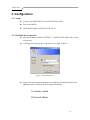
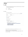
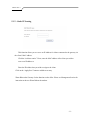
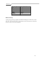
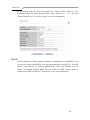
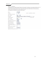
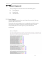
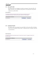
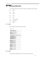
M505N
ADSL2+ Ethernet Broadband Gateway
802.11b/g/n 4 Port Ethernet USB 2.0
End User Manual
Manual Ver1.0
Table of Contents
1.
2.
INTRODUCTION ........................................................................................................................................................................ 4
1.1
FEATURES ........................................................................................................................................................................... 4
1.2
SYSTEM REQUIREMENTS ..................................................................................................................................................... 4
INSTALLATION .......................................................................................................................................................................... 5
FRONT PANEL .................................................................................................................................................................................... 5
REAR PANEL ...................................................................................................................................................................................... 6
CONNECTING THE HARDWARE .......................................................................................................................................................... 6
Step 1. Connect the ADSL cable and optional telephone.............................................................................................................. 6
Step 2. Connect the Ethernet cable............................................................................................................................................... 6
Step 3. Attach the power connector .............................................................................................................................................. 7
Step 4. Turn on the M505N and power up your systems ............................................................................................................... 7
Step 5. Configure the M505N through the WEB interface ............................................................................................................ 7
Step 6. Save the configurations and Reboot.................................................................................................................................. 7
3.
CONFIGURATION...................................................................................................................................................................... 8
3.1
SETUP ................................................................................................................................................................................. 8
3.2
ESTABLISH THE CONNECTION .............................................................................................................................................. 8
4.
QUICK VIEW............................................................................................................................................................................... 9
5.
LAN ............................................................................................................................................................................................. 10
5.1
LAN ................................................................................................................................................................................. 10
6. SECURITY ................................................................................................................................................................................... 12
7.
6.1
IP FILTERING ..................................................................................................................................................................... 12
6.2
URL FILTERING ................................................................................................................................................................ 14
6.3
PORT FORWARDING ........................................................................................................................................................... 15
6.4
PORT TRIGGERING ............................................................................................................................................................. 16
6.5
DMZ HOST ....................................................................................................................................................................... 17
6.6
WAN ACCESS CONTROL .....................................................................................................................................18
DNS.............................................................................................................................................................................................. 19
-2-
Manual Ver1.0
7.1
DYNAMIC DNS ................................................................................................................................................................. 19
8.
USB STORAGE (DLNA) ........................................................................................................................................................... 20
9.
IPSEC .......................................................................................................................................................................................... 21
10. WIRELESS ................................................................................................................................................................................. 24
10.1
SSID ................................................................................................................................................................................ 27
10.2
SECURITY SETTINGS .......................................................................................................................................................... 27
10.3
WPS................................................................................................................................................................................. 32
10.4
MAC FILTERING ............................................................................................................................................................... 32
10.5
WIFI BRIDGING ................................................................................................................................................................. 33
10.6
GLOBAL SETTINGS ............................................................................................................................................................ 34
11. SYSTEM DIAGNOSTIC ........................................................................................................................................................... 36
11.1
SYSTEM DIAGNOSTICS....................................................................................................................................................... 36
11.2
INBOUND TOOLKIT ............................................................................................................................................................ 37
11.3
OUTBOUND TOOLKIT ......................................................................................................................................................... 37
12. GATEWAY STATISTICS........................................................................................................................................................... 38
12.1
xDSL................................................................................................................................................................................ 38
12.2
ATM................................................................................................................................................................................. 38
12.3
WAN ................................................................................................................................................................................ 39
12.4
LAN ................................................................................................................................................................................. 40
12.5
HOSTS............................................................................................................................................................................. 40
12.6
WIRELESS CLIENTS ........................................................................................................................................................... 40
12.7
ROUTE .............................................................................................................................................................................. 41
12.8
DHCP............................................................................................................................................................................... 41
13. MANAGEMENT ........................................................................................................................................................................ 42
13.1
RUNNING CONFIGURATION ................................................................................................................................................ 42
13.2
NTP CLIENT ..................................................................................................................................................................... 42
13.3
MANAGEMENT ACCOUNTS ................................................................................................................................................ 43
13.4
WARM REBOOT ............................................................................................................................................................... 44
14. APPENDIX A – SPECIFICATIONS......................................................................................................................................... 45
15. APPENDIX B – WARRANTIES ............................................................................................................................................... 47
16. APPENDIX C – REGULATIONS............................................................................................................................................. 48
17. CONTACT INFORMATION .................................................................................................................................................... 50
-3-
Manual Ver1.0
1. Introduction
Congratulations on becoming the owner of the VisionNet M505N 802.11N ADSL2+
Broadband Gateway. You will now be able to access the Internet using your high-speed
ADSL/2+ connection. The Master series of ADSL2+ modems has the following major
features.
Features
•
ADSL/2/2+ modem for high speed Internet access
•
IEEE 802.11b/g/n wireless functionality
•
USB Storage for Media share across your Local Network
•
Network Address Translation (NAT) and IP filtering functions to provide
network sharing and firewall protection for your computers
•
Easy configuration via a WEB browser
•
SPI firewall to protect you from outside intruders and attacks
•
TR-069 compliant for automatic modem update through your high speed
Internet access
This End User Manual will guide you through the installation and configuration of your
M505N modem.
System Requirements
Before installing your M505N modem, make sure that you have the following:
•
ADSL service up and running on your telephone line, with at least one public Internet
address for your LAN
•
Computer containing an Ethernet 10Base-T/100Base-T network interface card (NIC)
For system configuration, use the web-based (HTTP) user interface.
Note: Make sure that your computer has a web browser such as Internet Explorer v7.0 or
later, or Firefox v3.0 or later.
-4-
Manual Ver1.0
2. Installation
In addition to this document, your M505N should arrive with the following:
•
•
•
•
•
One power adapter
One Ethernet cable with RJ-45 connector
One Telephone cable with RJ-11 connector
Product Installation CD
Installation Guide
Front Panel
The Front panel LED light indicates the status of the unit. (Left to Right)
M505N
Label
Power
Color
Green
Function
On – Solid Green
Off – The Modem is Off
Red – Power on self test/ Device Malfunction (not
bootable) and device malfunction
Malfunction is any state which would prevent
syncing or passing of data
DSL
Green
Green – DSL Good Sync
Off
- Powered off
Flashing Green - DSL Attempting sync
Internet
Green
Solid Green – IP connected – no traffic passing
Device has a public IP via either static/ DHCP/
or IPCP
If PPP is used it has been authenticated
If IP or PPPOE session is idle and dropped,
light to remain green as long as ADSL is still
present. Light to turn red if upon attempting
new session it fails.
Off – Modem Power Off.
LED Should remain off if modem is in bridged
mode
Ethernet 1-4
Green
Off - Power Off – or – No Device Detected on any LAN
port
Solid Green – Device connected including wake on LAN
on any LAN port
Flashing Green – LAN activity present
Wireless
Green
Green – Wireless is activated on modem
Flashing Green – Wireless activity is present
WPS
Green
Off - Modem off or no radio signal detected
Off - WPS function not active
Solid Green – Device
-5-
Manual Ver1.0
Flashing Green – Attempting WPS association
DLNA
Green
Green – USB storage connected
Off
- No device detected
Rear Panel
The connectors located at the rear panel have the following functions.
M505N
Interface
Function
Switch(Push Button)
Power switch on/off
Power
Connects to the power adapter cable
Reset Button
Resets unit’s configuration to factory default
DLNA
USB 2.0/1.1 connection: Connects external storage
device to gateway
Ethernet 1-4
RJ-45 connector: Connects to your PC’s Ethernet port,
or to the uplink port on your LAN’s hub/switch
ADSL
RJ-11 connector: Connects to your ADSL line
WPS
Activate the WPS security function
Wireless
Enable/Disable Wireless functionality
Connecting the Hardware
Connect the M505N to the phone jack, the power outlet, and your computer or network.
Before you begin, turn the power off for all devices. These include your
computer(s), your LAN hub/switch (if applicable), and the M505N.
WARNING
Step 1. Connect the ADSL cable and optional telephone
Connect one end of the phone cable to the RJ-11 connector on the rear panel of the M505N.
Connect the other end to the ADSL outlet provided by your service provider (normally MODEM
port of the included splitter).
Step 2. Connect the Ethernet cable
Connect one end of the Ethernet cable to the RJ-45 connectors on the rear panel of the M505N and
-6-
Manual Ver1.0
connect the other end to your PCs network adaptor (NIC). If you are connecting a LAN to the
Master series, attach one end of the Ethernet cable to a regular hub port and the other end to the
LAN port on the M505N.
Step 3. Attach the power connector
Connect the AC power adapter to the power connector on the M505N and plug in the adapter to a
wall outlet or power extension.
Step 4. Turn on the M505N and power up your systems
Press the Power switch on the back panel of the M505N to the ON position.
Boot up your computer(s) and any LAN devices such as hubs or switches.
Step 5. Configure the M505N through the WEB interface
Please refer to Chapter 3.
Step 6. Save the configurations and Reboot
Save the changes you made on the M505N and it will automatically reboot to make the settings
permanent.
-7-
Manual Ver1.0
3. Configuration
3.1 - Setup
Connect your M505N and PC with an RJ-45 Ethernet cable.
Turn on the M505N.
The default IP address of M505N is 192.168.1.254.
192.168.1.1
3.2 - Establish the Connection
Enter the IP address (default: 192.168.1.254)
192.168.1.1 of M505N in the address line of your
web browser.
A Dialogue Box will pop up to request the user to login. (Figure 1)
Figure 1. Login dialogue box
Please enter the management username/password into the fields then click on the
OK button (Please contact your ISP for login information).
Username: admin
Password: admin
-8-
Manual Ver1.0
4. Quick View
Quick View allows you to view all the major statistics and information of your VisionNet M505N
Gateway from one easy location on the WEB interface.
The following information is provided:
1. Device Info – Information such as Software revision and Driver version
2. DSL Status – Sync Rate (DSL Connection speed for Downstream and Upstream)
3. WAN Overview – WAN service information
4. ARP – Client connected to the VisionNet M505N Gateway
-9-
Manual Ver1.0
5. LAN
The LAN (Local Area Network) section allows the following settings to be configured
on the VisionNet M505N Gateway:
LAN Setup
IPv6 LAN Settings
5.1 - LAN
192.168.1.1
Input the IP Address and Subnet Mask of your M505N. (Default:
(Default:192.168.1..254)
192.168.1.1)
Check the box if you want to enable IGMP Snooping.
Disable/Enable DHCP Server, and change the starting and ending IP address of your
server pool if needed.
- 10 -
Manual Ver1.0
5.1.2 – Static IP Leasing
This function allows you to reserve an IP Address for clients connected to the gateway via
the client’s MAC address.
Click the “Add new entries” Form, enter the MAC address of the client you wish to
reserve an IP address to.
Enter the IP Address that you wish to assign to the client
Click on the “Apply/Save” button to add the new entry.
Warm Reboot the Gateway for the function to take affect. Please see Management Section for
instruction on how to Warm Reboot the modem.
- 11 -
Manual Ver1.0
6. Security
The Security section allows the following setting to be configured on the VisionNet
M505N Gateway:
IP Filtering Rules
URL Filtering
Port Forwarding
Port Triggering
DMZ Host
WAN Access Control
6.1 – IP Filtering Rules
Two functions are supported in the IP Filter function of the M505N Gateway: Outgoing
IP Filtering and Incoming Filtering.
Incoming IP Filtering
When the firewall option is enabled on a WAN or LAN interface, all incoming IP traffic
from the WAN is BLOCKED. However, incoming IP filter rules can be allowed by setting
up filtering rules. Choose “Add” to configure incoming IP filters. To remove, check the
item and click “Remove”.
- 12 -
Manual Ver1.0
The screen allows you to create a filter rule to identify incoming IP traffic by specifying a
filter name and at least one of the conditions below. All of the specified conditions in this
filter rule must be satisfied for the rule to take effect. Click “Save/Apply” to save and
activate the filter.
Outgoing IP Filtering
By default, all outgoing IP traffic from LAN is allowed, but some IP traffic can be
BLOCKED by setting up filters. Choose “Add” to configure outgoing IP filters. To remove,
check the item and click “Remove”.
The screen allows you to create a filter rule to identify outgoing IP traffic by specifying a
filter name and at least one of the conditions below. All of the specified conditions in this
filter rule must be satisfied for the rule to take effect. Click “Save/Apply” to save and
- 13 -
Manual Ver1.0
activate the filter.
6.2 – URL Filtering Rules
The M505N Gateway allow user to block or allow access to specific URL for clients
connected. Setup the URL filters by: Choose “Create New Rule” to add URL (Web
Address)
- 14 -
Manual Ver1.0
6.3 – Port Forwarding
Port Forwarding allows you to direct incoming traffic from WAN side (identified by
Protocol and External port) to the internal server with private IP address on the LAN side.
The Internal port is required only if the external port needs to be converted to a different
port number used by the server on the LAN side. A maximum of 32 entries can be
configured.
Click on “Create New Rule” to enter configuration page to add your own rule(s). Some
common used servers (Web, FTP, Mail, etc.) are already pre-defined for the M505N. User
can simply select the desired pre-defined application from the pull-down menu and assign
the IP address of the local PC for the ports to be forwarded to.
- 15 -
Manual Ver1.0
To delete the configured rule(s), check the “Remove” box of the specific rule(s) and click
on “Remove”.
6.4 – Port Triggering
Some applications require that specific ports in the Router's firewall be opened for access
by the remote parties. Port Trigger dynamically opens up the “Open Ports” in the firewall
when an application on the LAN initiates a TCP/UDP connection to a remote party using
the “Triggering Ports”. The Router allows the remote party from the WAN side to establish
new connections back to the application on the LAN side using the “Open Ports”. A
maximum of 32 entries can be configured.
- 16 -
Manual Ver1.0
Click on “Create New Rule” to enter the configuration page to add your own rule(s). You
can configure the port settings from this screen by selecting an existing application or
creating your own (Custom application) and click “Save/Apply” to add it.
To delete the configured rule(s), check the “Remove” box of the specific rule(s) and click
on “Remove”.
6.5 – DMZ Host
The DSL router will forward IP packets from the WAN that do not belong to any of the
applications configured in the Port Forwarding table to the DMZ host computer.
Enter the computer's IP address and click “Apply Specified DMZ Host” to activate the
DMZ host.
Click on the “Clear/Deactivate DMZ Host” button to disable the DMZ Host function.
- 17 -
Manual Ver1.0
6.6 – WAN Access Control
WAN Access Control allows users to create time of day restrictions to a specific LAN
device connected to the Router. Click “Create New Rule” to configure restriction rules. To
remove, check the item and click “Remove”.
- 18 -
Manual Ver1.0
To create a new WAN Access Control Rule:
1. Give the rule a name that can be easily be identified
2. The “Browser’s MAC Address” will show the MAC address of the client currently
connected to the gateway WEB Interface. Either select this option if you want the rules to
apply to the PC in use or check the Other MAC address radio box and enter the MAC
address of the client you wish for the rules to apply to
3. Check the “Block” box and enter the Time of Day (24hour format) of when you would like
the Rules to begin and end.
4. Click on the “Save/Apply” button to apply the new WAN Access Control Rule
7. DNS
7.1
– Dynamic DNS
The Dynamic DNS service allows you to give a dynamic IP address a static hostname in
any of the domains. This function allows your M505N to be more easily accessible from
various locations on the Internet.
Choose “Create New Client Service” to configure Dynamic DNS.
Before you proceed, please visit one of these two websites to receive your own Dynamic
DNS service: www.dyndns.org or www.tzo.com.
To remove, check the item and click “Remove”
- 19 -
Manual Ver1.0
Select your Dynamic DNS service provider from ‘D-DNS provider’, and enter your
registration information. Click “Submit Dynamic DNS Service” to save the configuration.
8. Network Access Storage (DLNA)
The M505N have the ability to share content of an USB storage device to Windows based
PC’s connected on the LAN.
To utilize this function: connect a USB storage device (External Hard drive, USB Thumb
Drive, etc.) to the USB port of the M505N gateway.
The M505N will recognize the device after a few seconds and the USB storage information
will appear in the WEB interface.
To browse the content of the storage device, select the “Browse” link located on the page.
An Explorer window will open and list the directories/files currently in the storage device.
- 20 -
Manual Ver1.0
9. IPSEC
The M505N also have the ability to create a VPN (Virtual Private Network) tunnel using
IPSec as the security measure. VPN allows user to remotely connect to a network using
their Broadband connection. Click on the “Create New Tunnel” to create new IPSEC
connection
- 21 -
Manual Ver1.0
Enter the following critical information in the VPN Tunnel Settings:
1. Enter a name for this IPSec connection.
2. Enter the Public IP address of the remote gateway in the next field.
3. Select “Subnet” for Tunnel access from local IP addresses.
4. Enter the network address for the “IP address for VPN” field. (If your IP is X.X.X.X the network
address is usually X.X.X.0 for class C addresses)
5. Enter the local subnet mask in the field.
6. Select “Subnet” for Tunnel access from local IP addresses.
7. Enter the network address for the “IP address for VPN” field. (Note: you can not have the same
network address for both local and remote networks.)
8. Enter the remote subnet mask in the next field.
9. Set the Key Exchange Method to “Auto(IKE)”
10. Select “Pre-Shared Key” for authentication method.
11. Enter a key for the “Pre-Shared Key” field.
12. Select Disable for “Perfect Forwarded Security”
13. Click “Save/Apply” to save this connection.
14. Click the Enable check box to activate this connection.
15. Configure the remote IPSec gateway in the same manner. However, the local ip parameters will
be remote ip parameters.
16. Once established, you can connect to clients in the remote network using their local IPs.
- 22 -
Manual Ver1.0
- 23 -
Manual Ver1.0
10.
Wireless
Some basic understanding of 802.11b/g/n wireless technology and terminology is useful when you
are setting up the Router or any wireless access point. If you are not familiar with wireless networks
please take a few minutes to learn the basics.
Wireless client requirements
All wireless client adapters compliant to 802.11n, 802.11g and/or 802.11b can communicate with
the M505N Wireless LAN environment. However, be aware that only 802.11n compliant wireless
clients are able to gain full benefity of the 270Mb/s (Max) bandwidth delivered by the M505N. It is
highly recommended to use only wireless client adapters that are Wi-Fi™ certified to ensure
smooth interoperability with the M505N’s Wireless functionality.
Radio Transmission
Wireless LAN or WLAN devices use electromagnetic waves within a broad, unlicensed range of
the radio spectrum to transmit and receive radio signals. When a wireless access point is present, it
becomes a base station for the WLAN nodes in its broadcast range. WLAN nodes transmit digital
data using FM (frequency modulation) radio signals. WLAN devices generate a carrier wave and
modulate this signal using various techniques. Digital data is superimposed onto the carrier signal.
This radio signal carries data to WLAN devices within range of the transmitting device. The
antennae of WLAN devices listen for and receive the signal. The signal is demodulated and the
transmitted data extracted. The transmission method used by the access point is called Direct
Sequence Spread Spectrum (DSSS) and operates in a range of the radio spectrum between 2.4GHz
and 2.5GHz for transmission.
Antennas
Direct the external antenna to allow optimization of the wireless link. If for example the antenna is
erect, wireless links in the horizontal plane are favored. Please note that the antenna characteristics
are influenced by the environment that is by reflections of the radio signal against walls or ceilings.
It is advisable to use the received signal strength as indicated by the wireless client manager to
optimize the antenna position for the link to a given client. Concrete walls weaken the radio signal
and thus affect the connection.
- 24 -
Manual Ver1.0
Wireless Range
Range should not be a problem in most homes or small offices. If you experience low or no signal
strength in some areas, consider positioning the Router in a location between the WLAN devices
that maintains a roughly equal straight-line distance to all devices that need to access the Router
through the wireless interface.
SSID
Wireless networks use an SSID (Service Set Identifier) to allow wireless devices to roam within the
range of the network. Wireless devices that wish to communicate with each other must use the same
SSID. Several access points can be set up using the same SSID so that wireless stations can move
from one location to another without losing connection to the wireless network. The M505N
operates in Infrastructure mode. It controls network access on the wireless interface in its broadcast
area. It will allow access to the wireless network to devices using the correct SSID after a
negotiation process takes place.
By default the M505N broadcasts its SSID so that any wireless station in range can learn the SSID
and ask permission to associate with it. Many wireless adapters are able to survey or scan the
wireless environment for access points. An access point in Infrastructure mode allows wireless
devices to survey that network and select an access point with which to associate. You may disable
SSID broadcasting in the web manager’s wireless menu.
Radio channels
The 802.11b/g/n standard allows several WLAN networks using different radio channels to be
co-located. The M505N supports multiple radio channels and is able to select the best radio channel
at each startup. You can choose to set the channels automatically or manually.
The different channels overlap. To avoid interference with another access point, make sure that the
separation (in terms of frequency) is as high as possible. It is recommended to keep at least 3
channels between 2 different access points.
The M505N supports all channels allowed for wireless networking. However, depending on local
regulations, the number of channels actually allowed to be used may be additionally restricted, as
shown in the table below.
- 25 -
Manual Ver1.0
Regulatory Domain
China
Europe
Israel
Japan
Jordan
Thailand
USA / Canada
Allowed Radio Channels
1 to 13
1 to 13
5 to 8
1 to 14
10 to 13
1 to 14
1 to 11
Wireless Security
Various security options are available on the M505N including open or WEP, 802.1x, WPA,
WPA-PSK, WPA2 and WPA2-PSK. Authentication may use an open system or a shared key.
Please see section 10.2 for more information.
- 26 -
Manual Ver1.0
10.1 - SSID
This page allows you to configure basic features of the wireless LAN interface. You can
enable or disable the wireless LAN interface, hide the network from active scans (no
broadcasting of your network name), set the wireless network name (also know as SSID),
and restrict the channels based on nation’s requirements.
Check “Enable Wireless” to enable wireless radio; or uncheck to disable.
“SSID” is the network name shared among all devices in a wireless network.
10.2 – Security Settings
Four types of wireless security are provided: Shared (WEP), 802.1x, WPA/WPA2, and
WPA/WPA2-PSK.
WEP
WEP (Wired Equivalent Privacy) provides security by encrypting data over radio waves
when data is transmitted from one end point to another. WEP is the weakest security
method but the easiest one to configure. To enable WEP, select the following items step by
step:
Network Authentication: Shared
Data Encryption: Enabled
Encryption Strength: 128-bit (recommended for better security) or 64-bit
Click “Set Encryption Key” to enter your WEP keys.
Four keys for both encryption strengths can be stored here. Enter 13 ASCII characters or
- 27 -
Manual Ver1.0
26 hexadecimal digits for 128-bit encryption keys. Enter 5 ASCII characters or 10
hexadecimal digits for 64-bit encryption keys. Select which key (1 ~ 4) to use from
“Current Network Key”. Click “Save/Apply” to save the configuration.
802.1X
802.1X addresses the WEP weakness by adding user authentication, via RADIUS server.
So you need to have your RADIUS server up and running before using 802.1X. To enable
802.1X, select “802.1X” in “Network Authentication”. Enter your RADIUS server IP
address, port number (default: 1812), and key. Follow the WEP security section to
configure your WEP key and select “Save/Apply” to save your configuration.
- 28 -
Manual Ver1.0
WPA/WPA2
WPA (Wi-Fi Protected Access) is the strongest wireless security provided by the M505N.
Like 802.1X, WPA must co-work with RADIUS server as well. To enable WPA, select the
following items step by step:
Network Authentication: WPA/WPA2
WPA Group Rekey Interval: in seconds. Default: 0 (no re-keying).
RADIUS Server IP Address/Port/Key: must match your RADIUS server.
WPA Encryption: TKIP (select AES or TKIP+AES for WPA2).
Check your supplicant capability before you decide which one to use.
- 29 -
Manual Ver1.0
WPA/WPA2-PSK
WPA-PSK lets you take advantage of WPA without the hassle of setting up your own
RADIUS server. To enable WPA-PSK, select “WPA-PSK” in “Network Authentication”.
Enter 8 to 63 ASCII codes or 64 hexadecimal (0~9, A~F) digits in “WPA Pre-Shared Key”.
Click “Save/Apply” to save the configuration.
*Note – You must also input the WPA Pre-Shared Key on the client side (i.e. Wireless
Laptop, Desktop, Game Consoles, etc.) to be able to connect to the modem. Please contact
the manufacturer of your device for more information.
- 30 -
Manual Ver1.0
- 31 -
Manual Ver1.0
10.3 – WPS (Wireless Security Settings)
This page is used to configure the settings for WPS (Wi-Fi Protected Setup). It uses a
push-button or a 4- or 8-digit personal identification number (PIN) to simplify the secure
network setup.
With WPS, M505N can automatically set the SSID or network name as part of the setup
process and provide strong encryption keys to client devices. You do not need to configure
SSID, wireless security setting, etc., in the client software. In order to use WPS, the
wireless client software must also support WPS.
10.4 – MAC Filter
Wireless MAC filter allows you to implement access control based on device’s MAC
address.
When you select “Allow” in “MAC Restrict Mode”, only data from devices with matching
MAC addresses in filter table can access the M505N. If you select “Deny” in “MAC
Restrict Mode”, every device can access the M505N except those which have matching
MAC addresses in the filter table. To add filter entry, click on “Add” and enter the MAC
address of the M505N. Click “Save/Apply” to save the configuration. To “delete” the entry,
select the entry and click “Remove”.
- 32 -
Manual Ver1.0
10.5 – Wireless Bridging
Wireless Bridge (also known as Wireless Distribution System) can bridge data between
two APs, which is particularly useful while wired cabling is not available.
Note: only APs in same channel can be bridged.
AP Mode: Wireless Bridge- listens and answers other APs only
Access Point- Wireless Bridge also with AP functionality
Bridge Restrict: Disabled- any AP will be granted access
Enabled- only selected APs (Max. 4) with specified MAC address will be
granted access
Enabled (Scan)- as above, but the M505N will scan available AP for you to
select.
Refresh: re-scan the available AP
Save/Apply: save the configuration
- 33 -
Manual Ver1.0
10.6 – Global Settings
System In most cases, M505N work well with wireless default settings. Modification is not
recommended unless you are very familiar with these parameters.
Channel: Select the appropriate channel from the provided list to correspond with your
network settings. All devices in your wireless network must use the same channel in
order to function correctly. Default: 11.
- 34 -
Manual Ver1.0
- 35 -
Manual Ver1.0
11.
System Diagnostic
The System Diagnostic section allows the tools for troubleshooting purpose
System Diagnostic
Inbound Toolkit
Outbound Toolkit
11.1 – System Diagnostic
The System Diagnostic function will run a test for Physical Port connectivity, DSL status,
and Internet WAN connection status.
The test takes a few second to complete. Once it is completed the results will be shown in
each category. In case of failure, rerun the test to ensure that the results are consistent.
Click on the Help link next to the test categories to get more information for
troubleshooting.
- 36 -
Manual Ver1.0
11.2 – Inbound Toolkit
This function allows you to ping device locally in your network. Type in the URL or IP
address of the device you would like to ping. If there is a Ping reply, that verify that the
connection is up and not block.
11.3 – Outbound Toolkit
This function allows you to ping devices on the WAN side. Type in the URL or IP address
of the device you would like to ping. If there is a Ping reply, that verify that the connection
is up and not block.
- 37 -
Manual Ver1.0
12.
Gateway Statistics
The Gateway Statistics section allows viewing of the following category statistics:
xDSL
ATM
WAN
LAN
Host
Wireless Clients
Route Table
DHCP
12.1 – xDSL
This will display all DSL statistics of the modem.
12.2 – ATM
This will display ATM statistics of the current active WAN connection:
- 38 -
Manual Ver1.0
12.3 – WAN Statistics
The WAN Statistics page is broken into 2 parts:
1. WAN Overview – Information concerning the WAN protocol currently in used by
the M505N to connect to the Internet. In the figure below: The modem is currently
in IPoE mode, IGMP option is disabled, PVC 0/35, the connection is Up and the
WAN IP address that the modem receives from the Internet Service Provider
Equipment.
2. Packet Statistics –Information concerning Packets Received and Transmitted on
the WAN side based on the Protocol used by the M505N (example shows IPoE
connection).
- 39 -
Manual Ver1.0
12.4 – LAN
This will display all LAN statistics of the M505N:
12.5 – Host
This will display all Host/ARP statistics of the M505N:
12.6 – Wireless Clients
This will display all devices that it currently connected to the M505N via the Wireless
connection.
- 40 -
Manual Ver1.0
12.7 – Route table
This will display all current Route table of the M505N:
12.8 – DHCP
This will display all DHCP Clients connected to the M505N
- 41 -
Manual Ver1.0
13.
Management
13.1 – Settings
This page allows backup the current configuration, restore the modems from a
configuration file or restore the modem to its default configuration.
If you wish to erase the running the configuration from the gateway and revert back to the modem
default settings: click on the “Restore Default Settings”.
13.2 – NTP Client
This option allows you to configure the NTP (Network Time Protocol) of the Gateway.
- 42 -
Manual Ver1.0
Select the Check box “Automatically synchronize with Internet time server” box.
Choose the NTP Server from the dropdown list
Finally, select the Timezone from the dropdown list.
Click the “Apply/Save” button for apply this function.
- 43 -
Manual Ver1.0
13.3 – Management Account
This page allows you to modify the log-in password to the management interface of the
gateway.
13.4 – Warm Reboot
Click “Warm Reboot” button to reboot M505N.
- 44 -
Manual Ver1.0
14.
Appendix A – Specifications
A1. Hardware Specifications
Local Interface
• Four 10/100BaseT Ethernet port (IEEE 802.3, RJ-45 connector)
• Two Removable External Wireless Antenna (Supports B/G/N mode)
• USB 2.0 Type A Interface
WAN ADSL Line Interface
• Complies with G.dmt (G.992.1) Annex A
• Complies with G.lite (G.992.2) and T1.413
• Complies with ADSL2 (G.992.3)
• Complies with ADSL2+ (G.992.5)
• Connector: RJ-11
OAM&P
• Remote: Telnet, SSH or Web browser
Environment
• Operation Temperature: 0°C ~ 40°C
• Operation Humidity: 10% ~ 95%
• Storage Temperature: -20 ~ 70°C
• Storage Humidity: 5%~95%
Power
• AC Adapter :Input 100-240V AC50/60Hz; Output 12VDC 1A
Certificates
• FCC Part 68 and 15 Class B, UL
A2. Software Specifications
ATM
• ATM Cell over ADSL, AAL5
• Supports UBR, CBR & VBR-nrt
• VPI Range (0-255) and VCI range (1-65535)
• Supports up to 8 PVCs
• Supports OAM F4/F5, and loop back cells
• Payload Encapsulation -− RFC2684 (RFC1483), multi-protocol over ATM
− RFC2364, PPP over ATM (CHAP and PAP supported)
− RFC2516, PPPoE (PPP over Ethernet) over ATM
•
•
•
•
•
•
•
•
•
•
•
•
Bridging
Transparent Bridging (IEEE 802.1D)
RFC2684 (RFC1483) Bridged
Spanning Tree Protocol (IEEE 802.1D)
Bridge Filtering
Routing
IP Address Forwarding
MAC Encapsulated Routing
Routing Information Protocol (RIP) v1, v2
DHCP Client (to the DSL network)
DHCP relay agent
NAT/PAT – RFC1631 (basic Firewall support)
Support Point-to-Point Protocol (PPP)
PAP for user authentication
- 45 -
Manual Ver1.0
•
•
•
•
RFC2684 (RFC1483) Routed
DNS relay
UPnP
IGMP-Proxy
•
•
•
•
Configuration and Network Management
DHCP server for IP management
HTTP (Web Server) for configuration and firmware upgrade
TFTP Server
FTP Server
•
•
•
•
•
•
•
•
Firewall
NAT ALG
IPSEC pass-through
Ping of Death
SYN Flood LAND
Protection against IP and MAC address spoofing
Packet Filtering
Stateful Packet Inspection (SPI)
UPnP NAT Traversal
- 46 -
Manual Ver1.0
15.
Appendix B – Warranties
DQ Technology adheres to the strictest Quality Assurance processes to ensure that our products are free from defects prior to
shipping. DQ Technology provides a standard 1 year limited warranty for all products and provides an extended warranty option for
North American customers.
Please note that standard warranty terms apply to all equipment sold by DQ Technology unless an extended warranty has been
purchased.
The 1 year limited warranty offered by DQ Technology Inc. is non-transferrable. End Users who purchased equipment from a
Service Provider, or other source, should contact the company from whom they purchased the equipment for all warranty and returns.
This warranty is not transferable and does not include service, repair, or replacement to correct any damage caused by improper
installation or maintenance, improper connection with any peripheral, external electrical fault, accident, disaster, misuse, abuse, or
modifications to the DSL modem not approved in writing by DQ Technology. All implied warranties are hereby limited to a One
(1) year term. DQ Technology hereby disclaims all express warranties not included in these terms.
DQ Technology warrants that all products are free from defective material and workmanship and, subject to the conditions set forth
below, agrees to repair or replace any part of a product, which proves defective by reason of improper workmanship or materials
without charge for parts and labor.
If a Product does not perform as warranted herein, owner's sole remedy shall be repair or replacement as provided below. In no
event will DQ Technology be liable for damages, lost revenue, lost wages, lost savings, or any other incidental or consequential
damages arising from purchase, use, or inability to use this product, even if DQ Technology has been advised of the possibility of
such damages. Any defective Product should be returned to the address above unless otherwise instructed by this notice, along with
a copy of your sales slip, the product serial number (if applicable), and a detailed description of the problem(s) you are experiencing.
No express or implied warranty is made for DQ Technology Products damaged by accident of use, misuse, natural or personal
disaster or any unauthorized disassembly, repair or modification.
DQ Technology's Warranty covers only repair or replacement of defective Products
DQ Technology is not liable for, and does not cover under Warranty, any costs associated with servicing or installation of Products.
If you experience any difficulty during installation or subsequent use of Products, please contact Technical Support at
1-866-286-XDSL or email [email protected].
DQ Technology warrants that all solid-state memory products are free from defect in material and workmanship. Subject to the
conditions and limitations set forth below, DQ Technology will repair or replace any part of a Product that proves defective by
reason of improper workmanship or materials.
Repair parts or replacement Products will be furnished on an exchange basis and will be either new or refurbished to be functionally
equivalent to new.
- 47 -
Manual Ver1.0
Appendix C – Regulations
C1. FCC Part 68 Statement
This equipment complies with Part 68 of the FCC rules and the requirements adopted by the ACTA. On the back
of this equipment is a label that contains, among other information, a product identifier in the format
US: DQ1DL01BM505N. If requested, this number must be provided to the telephone company.
The REN is used to determine the number of devices that may be connected to a telephone line. Excessive RENs
on a telephone line may result in the devices not ringing in response to an incoming call. In most but not all areas, the
sum of RENs should not exceed five (5.0). To be certain of the number of devices that may be connected to a line, as
determined by the total RENs, contact the local telephone company. For products approved after July 23, 2001, the
REN for this product is part of the product identifier that has the format US: DQ1DL01BM505N. The digits represented
by 01 are the REN without a decimal point (e.g., 03 is a REN of 0.3). For earlier products, the REN is separately shown
on the label.
If your equipment causes harm to the telephone network, the telephone company may discontinue your service
temporarily. If possible, they will notify you in advance. But if advance notice is not practical, you will be notified as
soon as possible. You will be informed of your right to file a complaint with the FCC. Your telephone company may
make changes in its facilities, equipment, operations or procedures that could affect the proper functioning of your
equipment. If they do, you will be notified in advance to give you an opportunity to maintain uninterrupted telephone
service.
If you experience trouble with this telephone equipment, please contact the following address and phone number
for information on obtaining service or repairs.
The telephone company may ask that you disconnect this equipment from the network until the problem has been
corrected or until you are sure that the equipment is not malfunctioning.
This equipment may not be used on coin service provided by the telephone company. Connection to party lines is
subject to state tariffs.
Company: DQ Technology, Inc.
Address: 5111 Johnson Drive, Pleasanton, CA, 94588
Tel no.: +1 925 730 3940
A plug and jack used to connect this equipment to the premises wiring and telephone network must comply with
the applicable FCC Part 68 rules and requirements adopted by the ACTA. A compliant telephone cord and modular plug
is provided with this product. It is designed to be connected to a compatible modular jack that is also compliant. See
installation instructions for details.
- 48 -
Manual Ver1.0
C2. FCC Part 15 Notice
This equipment has been tested and found to comply with the limits for a Class B digital device, pursuant to Part 15 of
the FCC Rules. These limits are designed to provide reasonable protection against harmful interference in a residential
installation. This equipment generates, uses and can radiate radio frequency energy and, if not installed and used in
accordance with the instructions, may cause harmful interference to radio communications. However, there is no
guarantee that interference will not occur in a particular installation. If this equipment does cause harmful interference
to radio or television reception, which can be determined by turning the equipment off and on, the user is encouraged to
try to correct the interference by one of the following measures:
Reorient or relocate the receiving antenna.
Increase the separation between the equipment and receiver.
Connect the equipment into an outlet on a circuit different from that to which the receiver is connected.
Consult the dealer or an experienced radio/TV technician for help.
CAUTION:
Any changes or modifications not expressly approved by the party responsible for compliance could void the
user's authority to operate the equipment.
C3. UL Safety Regulations
Disconnect TNV circuit connector or before removing cover or equivalent.
Disconnect TNV circuit connector(s) before disconnecting power.
Do not use this product near water for example, near a bathtub, washbowl, and kitchen sink or laundry tub, in a wet
basement, or near a swimming pool.
Avoid using a telephone (other than a cordless type) during an electrical storm. There may be a remote risk of
electric shock from lightening.
Do not use the telephone to report a gas leak in the vicinity of the leak.
Use only the power cord batteries indicated in this manual. Do not dispose of batteries in a fire, as they may
explode. Check with local codes for possible special disposal instructions.
No. 26 AWG Telephone Line Cord shall either be provided with the equipment or shall be described in the safety
instruction. If fuse (F1) is not present, see the caution statement listed below:
C4. IMPORTANT NOTE:
FCC Radiation Exposure Statement:
This equipment complies with FCC radiation exposure limits set forth for an uncontrolled environment. This
equipment should be installed and operated with minimum distance 20cm between the radiator & your body. This
transmitter must not be co-located or operating in conjunction with any other antenna or transmitter.
CAUTION: To reduce the risk of fire, use only No. 26 AWG or larger UL
Listed or CSA Certified Telecommunication Line Cord.
- 49 -
Manual Ver1.0
Contact Information
You can help us to serve you better by sending us your comments and feedback. Listed below are the addresses, and
telephone and fax numbers of our offices. You can also visit us on the World Wide Web at www.dqusa.com for more
information. We look forward to hearing from you!
World Headquarters
5111 Johnson Dr.
Pleasanton, CA 94588
Tel: (925) 730-3940 Fax: (925) 730-3950
[email protected]
Technical Support
(866) 286-xDSL (9375)
[email protected]
- 50 -