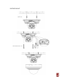
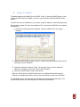
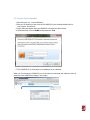
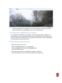
1
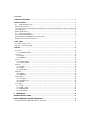
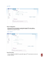
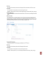
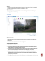
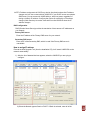
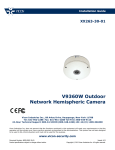
Installation Guide XX248-50-01 V992D-IR Indoor Network Dome Camera with IR LEDs Vicon Industries Inc., 89 Arkay Drive, Hauppauge, New York 11788 Tel: 631-952-2288 Fax: 631-951-2288 Toll Free: 800-645-9116 24-Hour Technical Support: 800-34-VICON (800-348-4266) UK: 44/(0) 1489-566300 Vicon Industries Inc. does not warrant that the functions contained in this equipment will meet your requirements or that the operation will be entirely error free or perform precisely as described in the documentation. This system has not been designed to be used in life-critical situations and must not be used for this purpose. www.vicon-security.com Document Number: 8009-8248-50-01 Product specifications subject to change without notice. Issued: 512 Copyright © 2012 Vicon Industries Inc. All rights reserved. Contents 1. PRODUCT FEATURES ......................................................................................................................... 1 2. INSTALLATION ..................................................................................................................................... 2 2.1 REMOVE DOME COVER ....................................................................................................................... 2 ADJUST IMAGE POSITION ................................................................................................................................ 2 THE ORIENTATION OF THE CAMERA UP AND DOWN ON THE POSITION OF THE IMAGE YOU WANT, PLEASE ADJUS T LEFT AND RIGHT. ........................................................................................................................................... 2 PORTS AND BUTTONS ..................................................................................................................................... 2 2.1 ASSIGN IP ADDRESS .......................................................................................................................... 5 2.3 ACCESS FROM A BROWSER ...................................................................................................................... 6 2.4 ACCESSING THE V992D-IR FROM THE INTERNET .................................................................................... 7 2.5 ADJUSTING THE IMAGE AND FOCUS .......................................................................................................... 7 3. LIVE VIEW ............................................................................................................................................ 8 3.1 VIDEO STREAM TYPES ........................................................................................................................... 8 3.2 HOW TO STREAM H.264 ........................................................................................................................ 9 4. SETUP ................................................................................................................................................. 10 4.1 INSTALL ................................................................................................................................................... 10 4.1.1 Installation Setup .......................................................................................................................... 10 4.2 VIDEO ..................................................................................................................................................... 11 4.2.1 Codec ............................................................................................................................................. 11 4.2.2 V992D-IR ....................................................................................................................................... 13 4.3 LIVE ........................................................................................................................................................ 15 4.3.1 Viewer Setup ............................................................................................................................... 15 4.3.2 Privacy Mask ............................................................................................................................... 15 4.4.FTP ........................................................................................................................................................ 17 4.4.1 Config ............................................................................................................................................ 17 4.4.2 Event ............................................................................................................................................. 17 4.4.3 Periodical ...................................................................................................................................... 18 4.5.EVENT .................................................................................................................................................... 19 4.5.1 Motion ............................................................................................................................................ 19 4.5.2 Mapping ........................................................................................................................................ 20 4.6 NETWORK .............................................................................................................................................. 20 4.6.1 IP Setup ........................................................................................................................................ 20 4.6.2 Service Port ................................................................................................................................. 22 4.6.3 E-mail ............................................................................................................................................ 23 4.7 SYSTEM.................................................................................................................................................. 23 4.7.1 User ............................................................................................................................................... 24 4.7.2 Date / Time .................................................................................................................................. 24 4.7.3 Maintenance ................................................................................................................................. 25 4.7.4 Information .................................................................................................................................... 27 6. DIMENSIONS ................................................................................................................................... 28 SHIPPING INSTRUCTIONS ................................................................................................................... 31 VICON STANDARD EQUIPMENT WARRANTY ................................................................................... 32 VICON PART NUMBER: 8006-9010-03-10 REV 0412............................................................................... 32 1. Product Features The V992D-IR is a high performance H.264 indoor network domecamer V992D-IR, designed for security installations. It delivers crisp, clear images, disclosing every detail, thanks to its top quality 3.0 Megapixel progressive CMOS sensor and advanced image processing. The camera provides the perfect solution for securing bank offices, airports and other facilities, and for traffic surveillance, over IP based networks. The optimal Power over Ethernet (IEEE 802.3af) support power to the V992D-IR to be delivered via the network, eliminating the need for a power outlet and reducing installation costs. Steady power could be guaranteed with a central Uninterruptible Power Supply (UPS). The V992D-IR offers a comprehensive set of network security and management features. This includes support for port based network control (IEEE802.1X), which allows the V992DIR to be connected to a network secured with this control, and HTTPS encryption, which provides a secure channel between V992D-IR and application. It also enables authentication of the video source. Video products are efficiently managed with the powerful V992D-IR Management tool, which is provided on the Installation CD which comes with each V992D-IR. 1. Network connector The V992D-IR connects to the network via a standard network cable, and automatically detects the speed of the local network segment (10BaseT/100BaseTX Ethernet). This socket could also be used to power the V992D-IR via Power over Ethernet (PoE). The V992D-IR auto-senses the correct power level when using a PoE (Class 2) switch, router or injector. 2. Reset Button Press this button to restore the V992D-IR configuration to its factory default settings. 1 2. Installation 2.1 Remove Dome Cover Turn counterclockwise the dome cover by grasping the bottom of the camera. Adjust Image Position The orientation of the camera up and down on the position of the image you want, please adjust left and right. Ports and Buttons 2 Mounting to a ceiling / wall IN CEILING MOUNT 3 SURFACE MOUNT 4 2.1 Assign IP address The default setting of the V992D-IR is set “DHCP” to ON. If you have a DHCP server on your network and UPnP function enabled on your PC you can find the network V992D-IR in “My network”. If a DHCP server is not available on your network, assign IP address by the following process: Execute Multi-Upgrade Tool (from the Installation CD). It will search V992D-IRs on the network automatically. 1) After the list of detected devices appears, select the V992D-IR you are trying to configure. 2) Select the Network type as Static or DHCP. If Static is selected, enter all of the network information for your V992D-IR. 3) Select the “Change IP Address” button. The message “Do you want to change IP address?” will display; select “Yes” from the pop-up window. 4) Check the Type as Static or DHCP from the list. When you double click the V992D-IR within the list, the default web browser (Internet Explorer or compatible equivalent) will open and automatically connect to the V992D-IR. The V992D-N4 can be accessed with most standard operating systems and browsers. The recommended browser is Internet Explorer® 7 and above for Windows®. 5 2.3 Access from a browser 1. Start a browser (i.e., Internet Explorer) 2. Enter the IP address or host name of the V992D-IR in the Location/Address field of your browser. Press Enter. 3. Login dialog will appear when the V992D-IR is accessed for the first time. 4. The default user name is ADMIN, and password is 1234. 5. The V992D-IR’s Live View page is now displayed in your browser. When you first access the V992D-IR you will be asked to download and install an Active X control from the V992D-IR to display a Live image. 6 NOTE: The layout of the live view page in the V992D-IR may have been customized to meet specific requirements. Consequently, some of the examples and functions featured here may differ from those displayed on your own Live View page. 2.4 Accessing the V992D-IR from the Internet Once installed, the V992D-IR is accessible on the local network (LAN). Configure the router/firewall to allow incoming data traffic to access the V992D-IR from the Internet. For security reasons this is usually done on a specific port. Please refer to the documentation for router/firewall for further instructions. 2.5 Adjusting the Image and Focus To adjust the position of the lens: 1. Open the Live View page in your web browser. - Select the Setup tab, and open the Installation page. - Select the ‘Video Format'. 2. Connect analog monitor to the VIDEO OUT (BNC) on the cable. - Adjust lens position and set FOCUS with supplied focus adjust ring. 7 3. Live View Digital Zoom Snap Shot Full Screen Video Stream change: First stream Second stream Play: Click this button by manually to start the stream Stop: Click this button by manually to stop streaming NOTE: It is possible that not all the buttons described below will be visible unless the Live View page has been customized to display them. 3.1 Video Stream Types Motion JPEG This format uses standard JPEG images in the video stream. These images are then displayed and updated at a rate sufficient to create a stream that shows constantly updated motion. The Motion JPEG stream uses a considerable amount of bandwidth, but it also provides excellent image quality and access to every individual image contained in the stream. H.264 protocols and communication methods • RTP (Real-time Transport Protocol) is a protocol that allows programs to manage the realtime transmission of multimedia data, via unicast or multicast. • RTSP (Real Time Streaming Protocol) serves as a control protocol, to negotiate the type of transport protocol to use for the stream. RTSP is used by a viewing client to start a unicast session. • UDP (User Datagram Protocol) is a communications protocol that offers limited service for exchanging data in a network which uses the Internet Protocol (IP). UDP is an alternative to the Transmission Control Protocol (TCP). The advantage of UDP is that, it is not required to deliver all data and may drop network packets when there is network congestion. This is suitable for live video, as there is no point in re-transmitting old information that will not be displayed anyway. • Unicasting is communication between a single sender and a single receiver over a network. This means that the video stream goes independently to each user, and each user gets own stream. A benefit of unicasting is, in case one stream fails, it only affects one user. 8 • Multicasting is bandwidth-conserving technology that reduces bandwidth usage by simultaneously delivering a single stream of information to multiple network recipients. This technology is used primarily on delimited networks (intranets), as each user needs an uninterrupted data flow and should not rely on network routers. (Note that multicasting may not be available with the firmware you received; check the Vicon website for updated firmware.) 3.2 How to Stream H.264 Deciding on the combination of protocols and methods to use depends on your viewing requirements, and on the properties of your network. Setting the preferred method(s) is done in webpage. RTP+RTSP This method (actually RTP over UDP and RTSP over TCP) should be your first consideration for live video, especially when it is important to always have an up-to-date video stream, even if some images are lost due to network problems. This could be configured as multicast or unicast. RTP/RTSP/Unicasting should be used for video-on-demand broadcasting, so that there is no video traffic on the network until a client connects and requests the stream. However, as more and more unicast clients get connected, the traffic on the network will increase and may cause congestion. Although there is a maximum of 10 unicast viewers, note that all multicast users combined count as 1 unicast viewer. RTP/RTSP This unicast method is RTP tunneled over RTSP. This could be used to exploit the fact that it is relatively simple to configure firewalls to allow RTSP traffic. 9 4. Setup The V992D-N4 is configured from the Setup link, which is available on the top left hand side in the web interface. This configuration could be done by: • Administrators, who have unrestricted access to all settings under the Setup tab. Accessing the Setup link from a browser 1. Start your web browser and enter the IP address or host name of the V992D-IR into the address bar. 2. The Live View page is now displayed. Click on the Setup tap. 4.1 Install 4.1.1 Installation Setup Installation Mode allows use of the analog BNC output from the V992D-IR to connect the V992D-IR NTSC, PAL: Analog Output is enabled. OFF: Analog output will be disabled. 10 4.2 Video The following descriptions show examples of some of the features available with V992D-N4. 4.2.1 Codec This section allows you to choose the compression codec for each of the video streams. Codec H.264 This is a video compression standard that makes good use of bandwidth and could provide high-quality video streams. The H.264 standard provides the scope for a large range of different coding tools for use by various applications in different situations, and the V992D-N4 provides certain subsets of these tools. Using H.264, it is also possible to control the bit rate, which in turn allows the amount of bandwidth usage to be controlled. CBR (Constant Bit Rate) is used to achieve a specific bit rate by varying the quality of the H.264 stream. While using VBR (Variable Bit Rate), the quality of the video stream is kept as constant as possible, at the cost of a varying bit rate. Motion JPEG This format uses standard JPEG still images in the video stream. These images then are displayed and updated at a rate sufficient to create a stream that shows constantly updated motion. The Motion JPEG stream uses considerable amounts of bandwidth, but also provides excellent image quality and access to every individual image contained in the stream. Multiple clients accessing Motion JPEG streams could use different image settings. 11 Size Video output resolution. See the output resolution table that follows. Frame rate 1 ~ 30fps (60Hz) / 1 ~25fps (50Hz) GOP Size 1 ~ 60 frames Bit-rate control (CBR or VBR) When using H.264 compression, if there is only limited bandwidth available, a constant bit rate (CBR) is recommended, although this may compromise image quality. Use a variable bit rate (VBR) for the best possibly image quality. Average Bit-rate (512Kbps ~ 10Mbps) Recommended bit rate for D1 or VGA : 800Kbps ~ 1Mbps Recommended bit rate for 1.3M (720p) : 3Mbps ~ 4Mbps Recommended bit rate for 2.0M (1080p) : 6Mbps ~ 8Mbps Boost Quality The Boost feature is used in conjunction with Video Motion Detection (VMD). When this feature is turned ON, the Boost FPS can be set to a different value than the Frame Rate set for the V992D-IR in the field above. When motion is detected, the V992D-IR will boost the fps from the regular level set for the V992D-IR to this boosted level for the duration of the motion. Boost Quality can be set ON or OFF. (Note that multicasting may not be available with the firmware you received; check the Vicon website for updated firmware.) Quality 1 ~ 100 This parameter is only available in M-JPEG mode. Anti-Flicker mode (Flicker less mode) 60Hz / 50Hz Video Mirroring Select Video Mirroring mode NONE/HORIZONTAL/VERTICAL/FLIP(H+V) 12 < Output resolution and Frame rate table for V992D-IR > (Unit: fps) First Stream Second Stream 1920x1080 704x480 640x480 640x360 640x352 352x288 352x240 320x240 - 1280x1024 704x480 640x480 640x360 352x288 352x240 320x240 - - 1024x768 704x480 640x480 640x360 352x288 352x240 320x240 - - 1280x720 1280x720 704x576 704x480 640x480 640x360 352x288 352x240 320x240 704x576 704x576 640x480 640x360 352x288 - - - - 704x480 704x480 640x480 640x360 352x240 - - - - 640x480 640x480 320x240 - - - - - - 640x360 640x360 320x240 - - - - - - 352x288 352x288 - - - - - - - 352x240 352x240 - - - - - - - 320x240 320x240 - - - - - - - 4.2.2 V992D-IR This section allows you to adjust various V992D-IR settings. This section allows you to adjust various V992D-IR settings. Exposure Control Exposure Mode 13 AUTO: Use this setting for automatic exposure control. MANUAL: Use this setting to control V992D-IR exposure manually. To compensate for poor lighting conditions, you can adjust the Color level, Brightness, Sharpness, Contrast and Exposure control. NOTE: When AE is enabled, some of the submenus (AGC Gain, e-Shutter Speed) will be disabled. AGC Gain 0 ~ 36 dB Slow shutter mode For low light conditions, turn on slow shutter mode. Max AGC Gain LOW/HIGH selectable. BLC Control (Back Light Compensation) The BLC adjusts the exposure of scenes with strong backlight in the center-bottom of the image. When the image background is too bright, or the subject too dark, backlight compensation makes the subject appear clearer. The settings for low light behavior determine how the V992D-IR behaves sat low light levels. These settings affect video image quality and how much noise is in the images. Day & Night Control Day & Night Mode Auto/Day/Night Set this filter to OFF to allow the V992D-IR to 'see' infrared light, removing the IR cut filter, when using an IR illuminator. This will make the image clearer. If set to Auto, the V992D-IR will automatically switch between IR cut filter On and Off, according to the current lighting conditions. 0/5/10/15/30/60 sec: Set detection window time in order to avoid failure switching. White Balance Control WB Mode AUTO: Automatic White balance MANUAL: Manual White balance The White balance adjustment setting is used to make the colors in the image appear consistent, compensating for the different colors present in different light sources. The V992D-N4 V992D-IR can be set to automatically identify the light source and compensate for its color temperature. If necessary, the type of light source could be set manually. Image Property Control Modify the video signal parameters, such as: Brightness, Sharpness, Contrast, and Color. Sharpness Brightness Contrast Color (Default: 8, Range: 1~15) (Default: 15, Range: 0~30) (Default: 15, Range: 0~30) (Default: 15, Range: 0~30) 14 4.3 Live V992D-N4 can support up to 10 simultaneous users via unicast. 4.3.1 Viewer Setup Live View Protocol RTP Unicast (UDP) / RTP over RTSP (TCP) Buffering Time (frame based) Determines (0 ~ 90) x 1/30 sec (0 ~ 3sec) Viewer OSD Setup Date: Determines whether the date is displayed. Resolution: Determines whether the V992D-IR resolution is displayed. Event State: Determines whether the event state is shown on display window (M for motion is shown in Live View). 4.3.2 Privacy Mask The IP Camera can support the Privacy Mask feature so a portion of the frame can be blocked based on personal preference or legal requirements. Log into WebRA web viewer and click on the Setup tab. Then choose Live from the menu on the left and select Privacy Mask. 15 Select the Area and Color for the mask and use the mouse to drag the cursor to fill the area to be set as a Privacy Mask. Click Save and then click the Live tab on the top to confirm the Privacy Mask satisfies preferences and/or requirements. 16 4.4.FTP 4.4.1 Config Server Configuration Allows transmission of still images to remote sites using the FTP server. Set the information for FTP transmission by inserting the IP address, Port, Username and Password of the remote FTP Server. 4.4.2 Event Event FTP Sending You can configure the V992D-IR to upload still images to FTP server based on event such as Motion detection. 17 Directory The name of the directory where the still images will be stored when an Event occurs. File Prefix You may add a file name prefix to the stored image file name. Example: If the file prefix is ‘MVD’, the still image would be saved as MVD_date_time.jpg. FTP Send Mapping Choose which types of events will be recorded to the FTP server by checking the desired event. Effective Period This parameter lets you decide whether to save all the events that are happening at all hours of the day, or only the events that occur within during specific times of the day. The Schedule method is used to save events into the FTP server during a specific time range. The start time and the end time can be set using the dropdown list. 4.4.3 Periodical Periodical FTP Sending It allows transmission of still images periodically to the FTP server. Directory The name of the directory where the still images will be stored. File Prefix You may add a file name prefix to the stored image file name. Example: If the file prefix is ‘per’, the still image would be saved as per_date_time.jpg. 18 Interval It allows for saving still images based on frequency (1 image every 10 sec, for example). Use the drop-down control to set from 10 seconds to 1 hour. Effective Period This parameter lets you decide whether to save still images at all hours of the day, or during specific times of the day. 4.5.Event 4.5.1 Motion Motion Detection Motion detection is used to generate an alarm whenever movement occurs within the video image. A total of 4 motion detection zones can be configured. Configuring Motion Detection 1. Click Motion in the Event menu. 2. Click Area1-4 button for the area to be defined and select the corresponding area for motion detection by clicking the relevant color box. 3. Click the box on the video image where the motion area is to be located and adjust the size of the area by dragging the outlined box across and down in one motion. 4. Adjust the Object Sensitivity from the drop down list, 1-10. The Sensitivity list only displays when an area is selected; it is not visible when All View is selected. Use the Selectall button to have the entire scene in the selected area. Deleteall is available to eliminate all selected areas. 5. Click Save. When motion occurs in the defined area, a red dot appears on the Live video. 19 NOTE: Using the motion detection feature will consume more of the V992D-IRs resources, and this could decrease the V992D-IR’s overall performance, depending on your settings. 4.5.2 Mapping Event Mapping It is possible to define conditions that would cause the V992D-IR to respond with certain actions. A triggered event happens as a result of an event that is mapped within this menu. This could be caused by motion detection. E-mail notification could be sent by Motion Event. 4.6 Network 4.6.1 IP Setup IP Address Configuration The IP address could be set automatically via DHCP, or a static IP address could be set manually. 20 NOTE: IP address assignment via DHCP may lead to the situation where the IP address changes and you lose contact with the V992D-IR. If your DHCP server can update a DNS server, you can access the V992D-N4 by a static host name, regardless of having a dynamic IP address. Configure the options for notification of IP address change (under Services) to receive notification from the V992D-IR when the IP address changes. DNS Configuration DNS (Domain Name Server) provides the translation of host names to IP addresses on your network. Primary DNS server Enter the IP address of the Primary DNS server for your network. Secondary DNS server Enter the IP of the Secondary DNS, which is used if the Primary DNS server is unavailable. How to assign IP address Execute the Multi Upgrade Tool (from the Installation CD); it will search V992D-IRs on the network automatically. 1) After the list of detected devices appears, select the V992D-IR you are trying to configure. 2) Select the Network type as Static or DHCP. If Static is selected, enter all of the 21 network information for your V992D-IR. 3) Select the “Change IP Address” button. The message “Do you want to change IP address?” will display; select “Yes” from the pop-up window. 4) Check the Type as Static or DHCP from the list. When you double-click the V992D-IR within the list, the default web browser (Internet Explorer or compatible equivalent) will open and automatically connect to the V992D-IR. 4.6.2 Service Port Service Port HTTP port The default HTTP port number (80) could be changed to any port within the valid port range (1-65535). This is useful for simple port mapping. RTSP port The RTSP protocol allows a connecting client to start an H.264 stream. Enter the RTSP port number to use. The default setting is 554. NOTE: After changing the default port numbers, the user can use the ‘Multi Upgrade Tool’ to search and connect automatically if they can’t remember the specific port numbers that they used. 22 4.6.3 E-mail You must turn Notification to ‘On’ and then enter the host names or addresses for your mail servers in the fields provided to enable the sending of event and error email messages from the V992D-IR to predefined addresses via SMTP. NOTE 1) Frequency: Mail server may register the sender to SPAM list if frequency is set to “1 Min”. To be safe, it may be better to set “5 Min”. NOTE 2) From: Specify the name that sent e-mail notification. It may be better to use e-mail format like [email protected], as some e-mail servers refuse certain formats. 4.7 System 23 4.7.1 User When you access the V992D-IR, the Configure Root Password dialog box appears. Enter the default user name ADMIN and password 1234 to log in. To change the password or add a user, go to Setup > System > User. Fill in the User ID, Password and E-mail address. Select the Group. Then press the ‘ADD’ button and click ‘SAVE’. NOTE: The default administrator username ADMIN is permanent and cannot be deleted or altered. 4.7.2 Date / Time Date & Time Format Specify the formats for the date and time (12h or 24h) displayed in the Live View video streams. NTP Server Synchronize the time from an NTP server every 60 minutes. Specify the IP address or host name of the NTP server you are using. Local Time / PC Sync/SAVE Specify Local time manually or Synchronize to PC time automatically. Time Zone Setup You may select your time zone from the drop-down list. D.S.T. (Daylight Saving Time) Toggle automatic DST clock adjustment on/off. 24 4.7.3 Maintenance System Name Choose a system name to identify the V992D-IR when using e-mail notifications. System Reboot Reboots the V992D-IR. Factory Default To reset the V992D-IR back to the original factory default settings. Firmware Update From time to time, CBC will release firmware updated for the PixelPro Series V992D-IR, which will contain feature additions and other improvements. Always read the upgrade instructions and release notes that accompany each new firmware release, before updating the firmware. NOTE: Preconfigured and customized settings should be saved before the firmware is upgraded. 25 Firmware Update Procedure 1. Save the firmware file to your computer. 2. Go to Setup > System > Maintenance within the V992D-IR web browser setup. 3. In the Firmware Update section, browse to the desired firmware file on your computer. Then click OK. NOTE: Do not disconnect power to the unit during the upgrade. The unit will restart automatically after the upgrade has completed (1~5 minutes). 4. If you suspect the firmware upgrade for the V992D-IR has failed, always wait at least 510 minutes before restarting the upgrade process. 5. Vicon reserves the right to charge for any V992D-IR repair which can be attributed to faulty upgrading by the user. Always read the upgrade instructions and firmware release notes before updating the firmware. System Reboot There are two ways to reset the V992D-IR. Case 1) Using the web browser: 1. Go to SETUP > System > Maintenance. 2. Click “System Reboot” button and wait 1 minute for V992D-IR to reboot. Case 2) Using the Reset Button of the V992D-IR: 1. Press and hold for 5 seconds, then release the button. Factory Default Reset There are two ways to reset the V992D-IR back to factory defaults. Case 1) Using the web browser: 1. Go to SETUP > System > Maintenance. 2. Click “Factory Default” button. Case 2) Using the Reset Button of the V992D-IR: 1. Push and hold the Reset button for more than 10 seconds. 2. Release the Reset button. NOTE: The unit will now have the default IP address from a DHCP server. Use the ‘Multi Upgrade Tool’ to discover and connect to the V992D-IR. 26 4.7.4 Information System Information Confirm the system information of the V992D-IR: S/W version/Model Name/MAC address/IP address settings. 27 6. Dimensions 28 29 Underwriters Laboratories Inc. (“UL”) has not tested the performance or reliability of the security or signaling aspects of this product. UL has only tested for fire, shock or casualty hazards as outlined in UL’s Standard(s) for Safety, UL60065. UL Certification does not cover the performance or reliability of the security or signaling aspects of this product. UL MAKES NO REPRESENTATIONS, WARRANTIES OR CERTIFICATIONS WHATSOEVER REGARDING THE PERFORMANCE OR RELIABILITY OF ANY SECURITY OR SIGNALING RELATED FUNCTIONS OF THIS PRODUCT. In USA and Canada, Use Class 2 Power Supply Only 30 Shipping Instructions Use the following procedure when returning a unit to the factory: 1. Call or write Vicon for a Return Authorization (R.A.) at one of the locations listed below. Record the name of the Vicon employee who issued the R.A. Vicon Industries Inc. 89 Arkay Drive Hauppauge, NY 11788 Phone: 631-952-2288; Toll-Free: 1-800-645-9116; Fax: 631-951-2288 For service or returns from countries in Europe, contact: Vicon Industries (U.K.) Ltd Brunel Way Fareham, PO15 5TX United Kingdom Phone: +44 (0)1489/566300; Fax: +44 (0)1489/566322 2. Attach a sheet of paper to the unit with the following information: a. Name and address of the company returning the unit b. Name of the Vicon employee who issued the R.A. c. R. A. number d. Brief description of the installation e. Complete description of the problem and circumstances under which it occurs f. Unit’s original date of purchase, if still under warranty 3. Pack the unit carefully. Use the original shipping carton or its equivalent for maximum protection. 4. Mark the R.A. number on the outside of the carton on the shipping label. 31 Vicon Standard Equipment Warranty Vicon Industries Inc. (the “Company”) warrants your equipment to be free from defects in material and workmanship under Normal Use from the date of original retail purchase for a period of three years, with the following exceptions: 1. 2. 3. 4. 5. 6. 7. 8. Monitors, all models: One year from date of original retail purchase. Uninterruptible Power Supplies: Two years from date of original retail purchase. VDR-700 Recorder Series: One year from date of original retail purchase. V5616MUX: One year from date of original retail purchase. Arecont V992D-IRs: One year from date of original retail purchase. FMC series fiber-optic media converters and associated accessories: Lifetime warranty. For PTZ V992D-IRs, “Normal Use” excludes prolonged use of lens and pan-and-tilt motors, gear heads, and gears due to continuous use of “autopan” or “tour” modes of operation. Such continuous operation is outside the scope of this warranty. Any product sold as “special” or not listed in Vicon’s commercial price list: One year from date of original retail purchase. Date of retail purchase is the date original end-user takes possession of the equipment, or, at the sole discretion of the Company, the date the equipment first becomes operational by the original end-user. The sole remedy under this Warranty is that defective equipment be repaired or (at the Company’s option) replaced, at Company repair centers, provided the equipment has been authorized for return by the Company, and the return shipment is prepaid in accordance with policy. The Company will not be obligated to repair or replace equipment showing abuse or damage, or to parts which in the judgment of the Company are not defective, or any equipment which may have been tampered with, altered, misused, or been subject to unauthorized repair. Software supplied either separately or in hardware is furnished on an “As Is” basis. Vicon does not warrant that such software shall be error (bug) free. Software support via telephone, if provided at no cost, may be discontinued at any time without notice at Vicon’s sole discretion. Vicon reserves the right to make changes to its software in any of its products at any time and without notice. This Warranty is in lieu of all other conditions and warranties express or implied as to the Goods, including any warranty of merchantability or fitness and the remedy specified in this Warranty is in lieu of all other remedies available to the Purchaser. No one is authorized to assume any liability on behalf of the Company, or impose any obligations on it in connection with the sale of any Goods, other than that which is specified above. In no event will the Company be liable for indirect, special, incidental, consequential, or other damages, whether arising from interrupted equipment operation, loss of data, replacement of equipment or software, costs or repairs undertaken by the Purchaser, or other causes. This warranty applies to all sales made by the Company or its dealers and shall be governed by the laws of New York State without regard to its conflict of laws principles. This Warranty shall be enforceable against the Company only in the courts located in the State of New York. The form of this Warranty is effective May 4, 2012. THE TERMS OF THIS WARRANTY APPLY ONLY TO SALES MADE WHILE THIS WARRANTY IS IN EFFECT. THIS WARRANTY SHALL BE OF NO EFFECT IF AT THE TIME OF SALE A DIFFERENT WARRANTY IS POSTED ON THE COMPANY’S WEBSITE, WWW.VICON-SECURITY.COM. IN THAT EVENT, THE TERMS OF THE POSTED WARRANTY SHALL APPLY EXCLUSIVELY. Vicon Part Number: 8006-9010-03-10 Rev 0412 32