1
YARDMACHINES
OWNER'S GUiD
Model Series
690 Thru 699
HYDROSTATIC LAWN
TRACTORS
IMPORTANT:
READ SAFETY RULES AND INSTRUCTIONS
CAREFULLY
Warning:
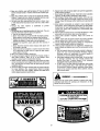
This unit is equipped with an internal combustion engine and should not be used on or near any unimproved forestcovered, brush-covered or grass-covered land unless the engine's exhaust system is equipped with a spark attester meeting
applicable local or state laws (if any). If a spark arrester is used, it should be maintained in effective working order by the operator.
In the State of California the above is required by law (Section 4442 of the California Public Resources Code). Other states may have
similar laws. Federal laws apply on federal lands. A spark arrester for the muffler is available through your nearest engine authorized
service dealer or contact the service department, P.O. Box 368022 Cleveland, Ohio 44136-9722.
MTD PRODUCTS
PRINTED
IN U.S.A.
INC.
P.O. BOX 368022 CLEVELAND,
OHIO 44136-9722
FORMNO.770-8253M
IMPORTANT
&
OPERATIONPRACTICES
THIS SYMBOL POINTS OUT IMPORTANTSAFETYIN ;TRUCTIONSWHICH, IF NOT FOLLOWED,COULD ENDANGERTHE PERSONAL
SAFETYAND/OR PROPERTY OF YOURSELF AND O-HERS. READ AND FOLLOW ALL INSTRUCTIONS IN THIS MANUAL BEFORE ,_IL
ATTEMPTINGTO OPERATEYOUR UNIT.WHENYOU S !ETHIS SYMBOL--
,_
DANGER:
,_
HEEDITS WARNING.
dlZ
Yourlawn mower was built t be operated accordingto the rules for safe operation in this manual. As with
any type of powerequipment carelessnessor error on the parl of the operatorcan resull in injury. This lawn
mower is capable of amputal ing handsandfeet and throwingobjects. Failure to observethe following safety
instructionscouldresult in st riousinjury or death.
GENERALOPERATION
20. Disengage all attachment clutches, thoroughly depress the
Read, understand, and follow all instructions in the n anual and
brake pedal, and shift into neutral before attempting to start
on the machine before starting. Keepthis manual in a safe place
engine.
21. Your mower is designed to cut normal residential grass of a
for future and regular reference and for ordering re _lacement
parts.
height no more than 10". Do not attempt to mow through
2. Only allow responsible individuals familiar with the ir structions
unusually tall, dry grass (e.g., pasture) or piles of dry leaves.
to operate the machine. Know controls and how t( stop the
Debris may build up on the mower deck or contact the engine
machine quickly.
exhaust presenting a potential fire hazard.
3. Do not put hands or feet under cutting deck or ne_r rotating
parts.
,_11.
SLOPEOPERATION
Slopes are a major factor relatedto loss of control and tip-over acci4. Clear the area of objects such as rocks, toys, wire, _tc., which
dents which can result in severe injury or death. All slopes require
could be picked up and thrown bythe blade. A small( bject may
extra caution. If you cannot back up the slope or if you feel uneasy
have been overlooked and could be accidentally thro Nn by the
on it, do not mow it.
mower in any direction and cause injury to you or a _ystander.
For your safety, use the slope gauge included as part of this manual
To help avoid a thrown objects injury, keepchildren, Lystanders
to measure slopes before operating this unit on a sloped or hilly
and helpers at least 75 feet from the mower while it i,, in operaarea. If the slope is greater than 15o as shown on the slope gauge,
tion. Always wear safety glasses or safety goggles du dng operdo not operate this unit on that area or serious injury could result.
ation or while performing an adjustment or repair, :o protect
eyes from foreign objects. Stop the blade(s) wher crossing
gravel drives, walks or roads.
5. Be sure the area is clear of other people before mov'ing. Stop
machine if anyone enters the area.
6. Never carry passengers.
7. Disengage blade(s) before shitting into reverse and b_cking up.
Always look down and behind before and while backir g.
8. Be aware of the mower and attachment discharge din ction and
do not point it at anyone. Do not operate the mow_r without
either the entire grass catcher or the chute guard in pl Ice.
9. Slow down before turning. Operate the machine ;moothly.
Avoid erratic operation and excessive speed.
10. Never leave a running machine unattended. Alway_ turn off
blade(s), place transmission in neutral, set park bf]ke, stop
engine and remove key before dismounting.
11. Turn off blade(s) when not mowing.
12. Stop engine and wait until blade(s) comes to a corn flete stop
before (a) removing grass catcher or unclogging chtte, or (b)
making any repairs, adjusting or removing any grass ( r debris.
13. Mow only in daylight or good artificial light.
14. Do not operate the machine while under the influence _falcohol
or drugs.
15. Watch for traffic when operating near or crossing roacways.
16. Use extra care when loading or unloading the mach ne into a
trailer or truck. This unit should not be driven up o down a
ramp onto a trailer or truck under power, becausethe _pnitcould
tip over, causing serious personal injury. The unit must be
pushed manually on a ramp to load or unload properl_
17. Never make a cutting height adjustment while engine i; running
if operator must dismount to do so.
,_
18. Wear sturdy, rough-soled work shoes and close-fitti zgslacks
and shirts. Do not wear loose fitting clothes or jewelry. They can
be caught in moving parts. Never operate a unit in Darefeet,
sandals, or sneakers.
19. Check overhead clearance carefully before driving unc er power
lines, wires, bridges or low hanging tree branches, bef__reentering or leaving buildings, or in any other situation v here the
operator may be struck or pulled from the unit, wh _h could
result in serious injury.
2
DO:
Mow up and down slopes, not across.
Remove obstacles such as rocks, limbs, etc.
Watch for holes, ruts or bumps. Uneven terrain could overturn the
machine. Tall grass can hide obstacles.
Use slow speed. Choosea low enough gear so that you will not have
to stop or shift while on the slope. Always keep machine in gear
when going down slopes to take advantageof engine braking action.
Follow the manufacturer's recommendations for wheel weights or
counterweights to improve stability.
Use extra care with grass catchers or other attachments. These can
change the stability of the machine.
Keep all movement on the slopes slow and gradual. Do not make
sudden changesin speed or direction. Rapid engagement or braking
could cause the front of the machine to lift and rapidly flip over
backwards which could cause serious injury.
Avoid starting or stopping on a slope. If tires lose traction, disengage the blade(s) and proceed slowly straightdown the slope.
DO NOT:
Do not turn on slopes unless necessary; then, turn slowly and gradually downhill, if possible.
Do not mow near drop-offs, ditches or embankments.The mower
could suddenly turn over if a wheel is over the edge of a cliff or
ditch, or if an edge caves in.
Do not mow on wet grass. Reduced traction could cause sliding.
Do not try to stabilize the machine by putting your foot on the
ground.
Do not use grass catcher on steep slopes.
III. CHILDREN
Trag_s
can occur if the operator is not alert to the presence
of children. Children are often attracted to the machine and the
mowing activity. Never assume that children will remain where you
last saw them.
1. Keep children out of the mowing area and in watchful care of an
adult other than the operator.
2. Be alert and turn machine off if children enter the area.
3. Before and when backing, look behind and down for small
children.
4. Nevercarry children, even with the blades off. They may fall off
and be seriously injured or interfere with the safe machine operation.
5. Neverallow children under 14 years old to operate the machine.
Children 14 years and over should only operate machine under
close parental supervision and proper instruction.
6. Use extra care when approaching blind corners, shrubs, trees
or other objects that may obscure your vision of a child or other
hazard.
7. Remove key when machine is unattended to prevent
unauthorized operation.
V. SERVICE
1. Use extreme care in handling gasoline and other fuels. They are
extremely flammable and the vapors are explosive.
a. Use only an approved container.
b. Never remove fuel cap or add fuel with the engine running.
Allow engine to cool at least two minutes before refueling.
c. Replacefuel cap securely and wipe off any spilled fuel before
starting the engine as it may cause a fire or explosion.
d. Extinguish all cigarettes, cigars, pipes and other sources of
ignition.
e. Never refuel the machine indoors because fuel vapors will
accumulate in the area.
f. Never store the fuel container or machine inside where there
is an open flame or spark, such as a gas hot water heater,
space heater or furnace.
2. Never run a machine inside a closed area.
3. To reduce fire hazard, keep the machine free of grass, leaves or
other debris build-up. Clean up oil or fuel spillage. Allow
machine to cool at least 5 minutes before storing.
4. Before cleaning, repairing or inspecting, make certain the blade
and all moving parts have stopped. Disconnect the spark plug
wire, and keep the wire away from the spark plug to prevent
accidental starting.
5. Checkthe blade and engine mounting bolts at frequent intervals
for proper tightness. Also, visually inspect blade for damage
(e.g., excessive wear, bent, cracked). Replacewith blade which
meets original equipment specifications.
6. Keepall nuts, bolts and screws tight to be sure the equipment is
in safe working condition.
7. Never tamper with safety devices. Checktheir proper operation
regularly. Use all guards as instructed in this manual.
8. After striking a foreign object, stop the engine, remove the wire
from the spark plug and thoroughly inspect the mower for any
damage. Repair the damage before restarting and operating the
mower.
9. Grass catcher components are subject to wear, damage and
deterioration, which could expose moving parts or allow objects
to be thrown. For your safety protection, frequently check components and replace with manufacturer's recommended parts
when necessary.
10. Mower blades are sharp and can cut. Wrap the blade(s) or wear
gloves and use extra caution when servicing blade(s).
11. Check brake operation frequently. Adjust and service as
required.
12. Muffler, engine and belt guards become hot during operation
and can causea burn. Allow to cool down before touching.
13. Do not change the engine governor settings or overspeed the
engine. Excessive engine speeds are dangerous.
14. Observe proper disposal laws and regulations. Improper disposal of fluids and materials can harm the environment and the
ecology.
a. Prior to disposal, determine the proper method to dispose of
waste from your local Environmental Protection Agency.
Recycling centers are established to properly dispose of
materials in an environmentally safe fashion.
b. Useproper containers when draining fluids. Do not use food
or beverage containers that may mislead someone into
drinking from them. Properly dispose of the containers
immediately following the draining of fluids.
c. DO NOT pour oil or other fluids into the ground, down a drain
or into a stream, pond, lake or other body of water. Observe
Environmental Protection Agency regulations when disposing of oil, fuel, coolant, brake fluid, filters, batteries, tires and
other harmful waste.
,_
WARNING _
YOURRESPONSlBILITY
Restrict the use of this power machine to persons who read,
understand and follow the warnings and instructions in this
manual and on the machine.
DANGER
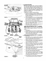
UNPACKING
TO REMOVE UNIT FROM CRATE
.
1. Remove all screws from the top of the c_ate using
a 1/4" hex head socket or a flat blade scl ewdriver.
2. To remove ends, grasp top board on the end, and
pull towards you in a downward motion.
3. Set panel aside to avoid tire punctures.
4. Repeat procedure for each side of the cr]te.
5. Remove
unit.
and discard
.
Loose parts (may include the owner's guide,
steering wheel, optional oil drain sleeve, battery
fluid, chute deflector, optional mulching kit, etc.)
are on the seat or in a box wrapped in plastic.
Carefully cut and remove the plastic wrap.
Remove the loose parts.
Make certain brake is released. Raise the deck.
Use the relief valve and push the unit off the skid.
plastic bag which covers
ASSEMBLY INSTRUCTIONS
IMPORTANT: After assembly, service engine
with gasoline, and check oil level as instructed
in the separate engine manual packed wi th your
unit.
NOTE: Reference to right or left hand skle of the
unit is observed from the driver's seat, fa :ing forward.
TOOLS REQUIRED FOR ASSEMBLY
(1)
(1)
(1)
(2)
1/4" socket wrench or flat blade screwdriv,=r
1/2" wrench or socket wrench*
9/16" wrench or socket wrench
7/16" wrenches or socket wrenches
E. NEVER connect or disconnect charger clips to
battery while charger is turned on as it can cause
sparks.
F. Keep all lighted materials (cigarettes, matches,
lighters) away from the battery as the hydrogen
gas generated during charging can be combustible.
G. As a further precaution, only charge the battery in
a well-ventilated area.
*Always shield eyes, protect skin and clothing
when working near batteries.
*If your steering wheel cap is square, you mu_t have a
socket wrench in order to install the steering _vheel.
BATTERYINFORMATION
_
WARNING
DANGER
A.
Battery acid must be handled with greal care as
contact with it can burn and blister the _;kin. It is
also advisable
to wear protective
clothing
(goggles, rubber gloves and apron) whet working
with it.*
B. Should battery acid accidentally splatter into the
eyes or onto the face, rinse the affec ed area
immediately with clean cold water. If the e is any
further discomfort, seek prompt medical a Ltention.
C.
If acid spills on clothing, first dilute it w th clean
water, then neutralize with a solution of a mmonia/
water or baking soda/water.
D. Since battery acid is corrosive, do not pc ur it into
any sink or drain. Before discarding empt_ electrolyte containers, rinse them with a neutraliz ing solution.
Battery contains sulfuric acid. Refer to warning
at right. Antidote: EXTERNAL--Flush with water.
INTERNAL--Drink
large quantities of water or milk.
Follow with milk of magnesia, beaten eggs or
vegetable oil. Call physician immediately. EYES:
Flush with cool water for at least 15 minutes, then
get prompt medical attention.
Since batteries produce explosive gases, keep
all
lighted
materials
(cigarettes,
lighters,
matches, etc.) away. Be sure to charge battery
only in well-ventilated areas. Make certain venting
path of battery drain tube (if equipped) is always
open.
KEEP BATTERIES
OUT OF THE REACH OF CHILDREN!
BATTERYIDENTIFICATION
CHARGE THE BATTERY after the 30 minute standing
period. Battery P/N 725-1705B--Charge
at 2-3 amps
for one hour. Battery P/N 725-1707B and 7250453E-Charge
at 6 amps for one hour.
NOTE: If you charge the battery at a lower AMP rate,
use a hydrometer to make sure the battery is comp/ete/y charged. The hydrometer should read 1.260
minimum at an electrolyte temperature of 60-110°F.
DO NOT CHARGE AT MORE THAN 6 AMPS.
Type "A"
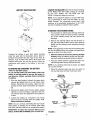
ATTACHING THE STEERING WHEEL
1. The hardware for attaching the steering wheel has
been packed inside the steering wheel. Carefully
pry off the steering wheel cap and remove the
hardware.
,
Type "B"
Compare the battery in your lawn tractor (located
under the seat) with the illustration above. Type "A"
batteries are activated and are ready to use. Type "B"
batteries must be filled with battery fluid (acid) and
charged before they are put into service. Follow the
instructions which apply to the battery in your lawn
tractor.
z,CTIVATING AND CHARGING THE BATTERY
'TYPE "B" BATTERY ONLY)
:)o not activate battery (fill with battery acid) until
_attery is actually placed in service. Be certain to
'ead previous battery warnings before activating
Ihe battery.
1. Pivot the seat forward. Unhook the strap which
secures the battery (hook is on rear frame, under
fender). Disconnect the positive cable from the
positive terminal. Save the hardware for reassembly.
Remove the steering bellow from the lift lever on
the right hand side of lawn tractor. Place steering
bellow over the steering shaft extending through
the dash.
NOTE: If the openings on each end of the steering bellow are two different sizes, the smaller end goes down
against the dash of the lawn tractor.
3. With the wheels of the tractor pointing straight
forward, place the steering wheel over the steering shaft, positioning steering wheel as desired.
4. Place the washer with the cupped side down over
the steering shaft. Secure with hex lock bolt.
NOTE: If your steering wheel cap is square, you must
use a socket wrench.
5. Place the steering wheel cap over the center of
the steering wheel and seat it with your hand.
Steering
Wheel Cap
Hex Lock
"_
Bolt _Cupped
2. Remove the battery from the lawn tractor, paying
attention to how the battery is placed in the unit,
and how the drain tube (attached to the battery) is
routed.
3. Activate the battery as instructed in the "Quick
Start" brochure included with the battery fluid.
Read instructions carefully.
NOTE: You can continue assembling the lawn tractor
while battery is standing for 30 minutes (after filling
with acid), and later while you are charging the battery.
IMPORTANT: To obtain the maximum life from your
battery, it MUST BE CHARGED prior to initial use.
Washer
Steering
Bellow
Steering
Shaft._.---- ----_
FIGURE 1.
_-
Screws
7
!
\
ATI'ACHING THE SEAT
Remove the four screws which secure the seat to the
seat pivot bracket. Turn the seat around and place in
position against the seat pivot bracket, lining up the
slotted holes in the pivot bracket with the holes in the
seat. Select desired position for the seat, and secure
with the four screws. See figure 2.
NOTE: Your seat may have been shipped in a box.
Remove the four screws from the bottom of seat and
place seat in position against the seat pivot bracket.
Follow the directions above to attach the seat.
FIGURE 2.
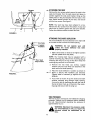
ATTACHINGTHE CHUTE DEFLECTOR
H .=xNuts
The chute deflector must be attached to the right side
of the deck so that it covers the chute opening.
(:upped
'ashers
_hb
unless the chute deflector
ARNING: Do not operate
properly installed.
has been
your unit
1. Make certain deck is raised to its highest position
(lift lever pulled all the way back).
NOTE: Your mowing deck may be equipped with a
optional mulching plug. Remove the mulching plug by
removing the wing nut on top of the deck. Grasp the
mulching plug and pull out of the deck.
2. Remove the hex head cap screws, cupped
washers and hex nuts which are attached to the
deck next to the chute opening.
Place the chute deflector in position as shown in
figure 3. Secure with hardware just removed.
Cupped sides of washers go against the chute
deflector.
FIGURE 3.
.
If you wish to mulch, lift up the chute and insert
optional mulching plug through chute opening.
Line up the bolt on mulching plug with the hole in
the top of deck. Push up on the end of the mulching plug and secure with the wing nut.
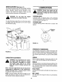
TIRE PRESSURE
The tires on your unit may be over-inflated for shipping
purposes. Reduce the tire pressure before operating
the unit. Recommended operating tire pressure is
approximately 12 p.s.i.
_
any circumstances is 30 p.s.i. Equal tire
ARNING: Maximum tire pressure under
pressure should be maintained on all
tires.
,ckHanger
<--LEVELING THE DECK
_-_
ustable/
With unit on hard, level surface, measure the distance
from the bottom edge of the center of the left side of
deck to the ground. Measure the same distance on the
center of the right side of the deck, just behind the
chute area. Or, place the blades in a straight line, and
measure the distance from the outside edge of the
blade tips to the ground.
If adjustment is needed, proceed as follows.
1. Remove the hairpin clip and flat washer from the
bottom of the adjustable lift link on the left side of
the deck. (Hairpin clip and flat washer are on the
inside of the lift link.)
"IGURE 4.
L
Positive Terminal
(Inside Rubber Boot)
il
U
Battery
Q
2. Pull the adjustable lift link out of the deck hanger
channel. See figure 4. Turn the adjustable lift link
up or down as necessary to level the deck.
Usually only one or two turns are needed.
3. Insert the end of the adjustable lift link into the
hole in the deck hanger channel. Recheck the
adjustment. Readjust if necessary.
4. When deck is level, secure end of adjustable lift
link with flat washer and hairpin clip.
INSTALLING THE BATTERY(TYPE "A" BATTERY)
/
NOTE: If battery is put into service after date shown
on top of battery, charge for minimum of 1 hour at 6-10
amps.
1. Lift the seat.
2. Remove the plastic cover from the negative terminal.
3. Remove the hex bolt and nut from the negative
(black) cable. Attach negative cable to the negative terminal with this bolt and nut.
Negative
Cable
FIGURE 5.
Negative
Terminal
Battery
Compartment
INSTALLING THE BATTERY(TYPE "B" BATTERY)
Battery
1. Lift the seat.
2. Make certain both the negative (black) cable and
the positive (red) cable are routed up through the
battery compartment as shown in figure 5.
3. Replace the battery into the battery compartment
in the same position as it was before (positive terminal is toward the front of the unit).
Slot
4. Attach the positive (red) cable to the positive
terminal of the battery. Secure with hex bolt and
nut previously removed. Slide rubber boot down
over the positive terminal.
5. Remove the hex bolt and nut from the negative
(black) cable. Attach negative cable to the negative terminal with this bolt and nut.
6. Secure battery by hooking battery strap into slot in
rear frame, under the fender. See figure 6.
7. Insert the drain tube through the hole in the transaxle reinforcement bracket located on the right
side of the unit. See figure 6. Be certain drain tube
is routed away from the wheel rim.
FIGURE 6.
Reinforcement
Bracket
8. Trim excess end of drain tube if necessary (about
4" should extend past the bracket or cable tie).
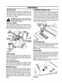
CONTROLS
IGNITION SWITCH
HYDROSTATICCONTROL LEVER
The ignition switch is located on the dashlo3ard. The
engine is started by turning the key to the ST _,RT position. When the engine is running, leave the {ey in the
ON position. To stop the engine, turn the _ey to the
OFF position. See figure 7.
The hydrostatic control lever is located on top of the
fender on the right side of the tractor. This single control lever, connected to the hydrostatic transmission,
controls both the speed and direction of the tractor.
Infinite speed control is achieved by moving the control
lever forward or backward. The farther forward or backward you move the control lever, the faster you will
travel. Pulling the control lever into neutral (N) area will
stop the tractor. See figure 8.
tor
when theRemove
tractor the
is not
u.,ethe
to tracpreWARNING:
key in
from
vent accidental starting.
_b
THROTTLE CONTROL
The throttle control is located on the dashbo=Lrd and is
used to regulate the engine speed. To get -naximum
efficiency from cutting, the throttle should )e in the
FAST position when operating the mower. Se_ figure 7.
Light
Choke,
Throttle
Hydrostatic
Control
Lever
/
_-_
Ignitior
"__ Lift
_
Lever
Ammeter
[Optional)
FIGURE 8.
CLUTCH-BRAKE PEDAL
The clutch-brake pedal is located on the left side of the
tractor. See figure 7. Depressing the pedal returns the
drive unit to neutral (N) and applies the brake.
Clut "h-Brake
Pedal
FIGURE 7.
CHOKECONTROL
The choke control is located on the dashboard and is
operated manually. Details for the choke openation are
covered in the separate engine manual packed with
your unit. See figure 7.
NOTE: The clutch-brake pedal must be depressed to
start the engine.
PARKING BRAKE
To set the parking brake, depress the clutch-brake
pedal, pull up the parking brake knob and release the
clutch-brake pedal. It will stay in the raised position. To
release the parking brake, depress and release the
clutch-brake pedal. See figure 9.
NOTE: The parking brake must be set if the operator
leaves the seat with the engine running.
LIGHT SWITCH (Optional)
The head lamps are operated by pushing the light
switch located on the dashboard. The head I_imps will
only operate when the engine is running. See figure 7.
AMMETER (Optional)
The ammeter registers the rate of battery ¢ harge or
discharge. The ammeter will register on the qfischarging side with starting the engine. It should re ;lister on
the opposite side (charging) when the engin is running in the fast position until the battery is c( mpletely
charged. With a fully charged battery or with the
engine idling, the ammeter will not show a ch_ rge. See
figure 7.
FIGURE 9.
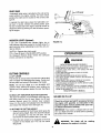
IELIEFVALVE
Lift Lever
hydrostatic relief valve is provided so the unit can be
noved without the engine running. The lever which
Iperates the relief valve is located on the console. See
igure 9.
o operate the relief valve, place the hydrostatic conrol lever in neutral, release the parking brake, push
he lever forward and to the right to lock. Be certain to
elease the lever by pushing it to the left before operatng the engine.
O
Lift Indicator °
NDICATOR LIGHTS (Optional)
f your unit is equipped with indicator lights, two or
:hree indicator lights are located in the dash panel. If a
ight illuminates when attempting to start the unit, pro_'eed as follows.
3LUTCH--Depress the clutch pedal.
PTO--Place lift lever in the BLADES OFF position.
OIL (Vanguard Engines Only)--Check the crankcase
3il level, and add oil as required.
FIGURE 10.
OPERATION
WARNING
AVOID SERIOUS INJURY OR DEATH
CUTTING CONTROLS
A. LIFT LEVER
The lift lever is used to raise and lower the cutting deck
and to engage and disengage the blades. Pulling it all
the way back and locking it disengages the blades.
NOTE: The rift lever must
be in the BLADES
OFF
position when starting the engine, when shifting into
reverse and if the operator leaves the seat. See figure
10.
B. DECK LIFT INDICATOR (Optional Equipment)
The deck lift indicator (if so equipped) marks the position being used for the lift lever. Select the lift lever
position desired, press the indicator lever outward,
move it to the position immediately below the lift lever
and release the indicator lever. See figure 10.
C. SETTING THE CUTTING HEIGHT
1. Select the position for the lift lever which gives the
desired cutting height. Move the deck lift indicator
(if so equipped) so that the lift lever can be
returned to the same position after it is raised.
2. Move the deck wheels (if so equipped) to the hole
location so the wheels are 1/4 to 1/2 inch above
the ground.
• GO UP AND DOWN SLOPES, NOTACROSS.• AVOID SUDDENTURNS.
• DO NOTOPERATETHE UNIT WHERE IT COULDSLIP OR TIP.
• IF MACHINE STOPS GOING UPHILL, STOP BLADE(S) AND BACK
DOWNHILL SLOWLY.
• DO NOT MOW WHEN CHILDREN OR OTHERSARE AROUND•
• NEVERCARRY CHILDREN.
• LOOKDOWN AND BEHIND BEFOREAND WHILE BACKING.
• KEEP SAFETY DEVICES (GUARDS, SHIELDS, AND SWITCHES) IN
PLACEAND WORKING.
• REMOVEOBJECTSTHAT COULD BETHROWN BYTHE BLADE(S).
• KNOW LOCATIONAND FUNCTIONOFALL CONTROLS•
• BE SURE BLADE(S) AND ENGINE ARE STOPPED BEFOREPLACING
HANDSOR FEETNEARBLADE(S).
• BEFORE LEAVING OPERATOR'S POSITION, DISENGAGE BLADE(S),
PLACETHE SHIFT LEVER IN NEUTRAL,ENGAGEBRAKELOCK, SHUT
ENGINEOFFAND REMOVEKEY.
READ OPERATOR'S MANUAL
GAS AND OIL FILL-UP
Check the oil level and add if necessary. Service
the engine with gasoline as instructed in the
separate engine manual packed with your tractor. Read instructions carefully.
IMPORTANT: Your tractor is shipped with oil; however you must check the oil level before operating.
Be careful not to overfill.
WARNING: The blade will be
whenever the engine is running,
rotating
STARTING THE ENGINE
IMPORTANT: This unit is equipped with a safety
interlock system for your protection. The I: urpose of
the safety interlock system is to prevent tl_e engine
from cranking or starting unless the clutoh-bu ake pedal
is depressed and the lift lever is in the BLA 3ES OFF
position. In addition, the lift lever must I_e in the
BLADES OFF position when the unit is put into
reverse or the engine will shut off. If the operator
leaves the seat with the lift lever engaged ar d/or without setting the parking brake, the engine will shut off.
_bb
WARNING:
ing up.
To stop the lawn tractor, pull the hydrostatic control
lever into NEUTRAL (N) or depress the clutch-brake
pedal.
Be sure that the lawn is clear of stones, sticks, wire, or
other objects which could damage lawn tractor or
engine. For best results and to insure more even grass
distribution, do not mow when lawn is excessively wet.
WARNING:
the interlock system is malfurctioning
ARNING: Do not operate the l ractor if
because it is a safety device, desi gned for
protection.
_b)
1. Place the lift lever in the BLADES OFF p3sition.
2. Depress the clutch-brake pedal and set the parking brake.
3. Place the hydrostatic
NEUTRAL (N) position.
control
lever
in
Look to the rear before back-
Before leaving the operator's
position place
for any
reason, disengage
the
blades,
the hydrostatic
control lever
in neutral, engage the parking brake, shut
engine off and remove the key.
When stopping the unit to empty a grass bag, etc., follow the instructions above. This procedure will also
eliminate "browning" the grass, which is caused by hot
exhaust gases from a running engine.
the
GRASS COLLECTORAVAILABLE
4. Set the throttle control in the FAST positi )n.
Grass Collector Model 190-063-000 is available as
optional equipment for lawn tractors with 38" and 42"
decks. Grass Collector Model 190-103-000 is available
for lawn tractors with 46" decks.
5. Pull out the choke control (a warm engine; may not
require choking).
6. Turn the ignition key to the right to th._ START
position. After the engine starts, release he key. It
will return to the ON position.
,_
NOTE; Protect the starter life by using shot t starting
cycles of several seconds. Cranking more than 15
seconds per minute can damage the starter r _otor.
operated without the entire grass catcher
WARNING: The mower should not be
or chute deflector in place.
NOTE: Under normal usage bag material is subject to
wear, and should be checked periodically. Be sure to
use only factory authorized replacement bag.
7. Push choke knob in gradually. Move th._ throttle
control to desired engine speed.
STOPPING THE ENGINE
Turn the ignition key to the left to the OFF position.
Remove the key to prevent accidental startinc.
IMPORTANT: If you strike a foreign object, stop the
engine. Remove wire from spark plug, thoroughly
inspect the unit for any damage, and repair the
damage before restarting and operating the rTower.
NOTE: If any problems are encountered,
Trouble Shooting Guide on page 17.
ADJUSTMENTS
ret_r to the
_
OPERATINGTHE LAWN TRACTOR
wires and ground against the engine
WARNING: Disconnect the spark plug
before
performing
any
adjustments,
repairs or maintenance.
SEAT ADJUSTMENT
1. Move throttle control to full throttle to prevent
strain on the engine and to operate thl; cutting
blades.
2. Depress the clutch-brake pedal so the parking
brake is released, and then release the, clutchbrake pedal.
3. Place the hydrostatic control lever in either the
FORWARD or REVERSE position. The farther
forward you move the hydrostatic control I ;ver, the
faster you will travel.
To adjust the position of the seat, loosen the four
screws on the bottom of the seat. See figure 2. Slide
the seat forward or backward as desired. Retighten the
four screws.
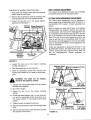
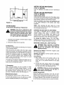
HYDROSTATICNEUTRAL CONTROLADJUSTMENT
The hydrostatic transmission control is in correct
adjustment when the tractor does not move with the
engine running, the clutch engaged and the hydrostatic control lever in the neutral position.
10
If adjustment
is necessary,
followthesesteps:
1. Raisebothrearwheelsoff thegroundby placing
blocksunderthe rearframe.
2. Removethe transmission
panelby removingthe
parkingbrakeknobandtrussmachinescrews.
3. Loosenthe hexjam nut on the speedselector
adjustingrod.Seefigure11.
Scissor
Bracket
Speed Selector
Adjusting Rod
DECKLEVELINGADJUSTMENT
If an uneven cut is obtained, the deck may be leveled
by following instructions in Assembly section.
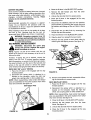
CUTTING DECK ENGAGEMENTADJUSTMENT
The cutting deck engagement may be adjusted to
make certain deck is disengaged when lift lever is in
the BLADES OFF position. Correct adjustment as
follows.
With the engine off, place the lift lever in the highest
cutting position (first position). Remove the cotter pin
and flat washer which secure the disengagement rod
to the stabilizer shaft assembly. See figure 12. Shorten
the rod by threading it in until the ferrule is against the
back of the slot in the lift shaft assembly, and the rod
lines up with the hole in the stabilizer shaft. For more
belt tension the disengagement rod must be lengthened. To decrease belt tension the disengagement rod
must be shortened.
Hex Nut
Scissor
Mounting
Bracket
Check the adjustment by placing the lift lever in
BLADES OFF position. The deck should move up
forward, allowing the belt to become loose. Start
test for disengagement.
Repeat
procedure
necessary.
Hex Jam Nut
(Loosen)
the
and
and
as
FIGURE 11.
4. Loosen the hex nut on the scissor
bracket. See figure 11.
mounting
Stabilizer Shaft
Assembly
5. Start the engine and run at full throttle.
Disengagement
Rod
6. Move the hydrostatic control lever until you find
neutral (rear wheels do not rotate in either direction).
,_
whenever
engine
is running.
WARNING: theThe
blade
will be
7. DeprEss the clutch-brake
brackets come together.
rotating
pedal until the scissor
8. Shut off the engine.
9. Tighten the hex nut on the scissor
bracket.
FlatWasher
I 36" and
Hairpin Clip
138" Decks
Stabilizer Shaft
Assembly
mounting
Disengagement
Rod
10. Thread the speed selector rod in or out of the ferrule until the hydrostatic control lever lines up in
the neutral position on the speed control index
bracket.
11. Tighten hex jam nut against the ferrule.
Stabilizer Plate
12. Replace the transmission panel and parking brake
knob.
Flat Washer
Hairpin Clip
13. Remove the blocks from under the frame and test
the operation of the tractor.
FIGURE 12.
11
42" and
46" Decks
BRAKEADJUSTMENT (See figure 13)
The brake is located by the right rear wheel ir side
frame. The brake has been set at the factoly to
proper clearance. During normal operation of
machine, the brakes are subject to wear and
require periodic examination and adjustment.
LUBRICATION
the
the
this
will
&
WARNING: Always stop engine and disconnect spark plug wire before cleaning,
lubricating or doing any kind of work on
lawn tractor.
STEERING GEARS
Lubricate teeth of steering gears with automotive
multi-purpose grease after every 25 hours of operation
or once a season. See figure 14.
running whenDo
younot
adjust
the brake..
WARNING:
have
the engine
To adjust the brake, adjust the nut so the brat:e starts
to engage when the brake lever is 1/4" to 5/1 3" away
from the axle housing.
STEERINGSHAFT
Lubricate steering shaft at least once a season with
light oil.
_'_
_.Steerirng
Lever
!
'_ _
\
Disc
- Brake
1
FIGURE 14.
\
HYDROSTATICTRANSMISSION
The hydrostatic transmission is filled at the factory and
does not require checking. If repairs are needed, contact your local service dealer. (Hydrostatic transmission contains approximately 2.5 quarts of SAE 20W50
oil.)
FIGURE 13.
LINKAGE
CARBURETORADJUSTMENTS
Once a season lubricate all the pivot points on the
clutch, brake and lift linkage with SAE 30 engine oil.
WARNING: If any adjustments are rmde to
the engine while the engine is running
(e.g. carburetor), disengage all c utches
and blades. Keep clear of all tnoving
parts. Be careful of heated surfacss and
muffler.
WHEELS
The front wheels are provided with grease fittings. The
rear wheels must be removed from the axle for lubrication. Lubricate at least once a season with automotive
multi-purpose
Minor carburetor adjustments may be reqL ired to
compensate for differences in fuel, temperature,
altitude and load. Refer to separate engine "nanual
for carburetor adjustment information.
grease.
PIVOT POINTS
Lubricate all pivot points with light oil at least once a
season.
BALLJOINTS
NOTE: A dirty air cleaner will cause an engine: to run
rough. Be certain air cleaner is clean and atta _hed to
the carburetor before adjusting carburetor.
The ball joints and drag link ends are permanently
lubricated.
12
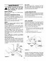
FUELFILTER
MAINTENANCE
Your unit is equipped with a replaceable in-line fuel
filter. Replace filter whenever contamination or discoloration is noticed. Order replacement filter through
your authorized engine service dealer.
wire and ground against the engine
WARNING: Disconnect the spark plug
before
performing
any
adjustments,
repairs or maintenance.
TROUBLE SHOOTING
CLEANING ENGINE AND DECK
Refer to the chart on page 17 for trouble shooting
engine problems.
Any fuel or oil spilled on the machine should be wiped
off promptly. Grass, leaves, and other dirt must not be
left to accumulate around the cooling fins of the engine
or on any part of the machine.
HYDROSTATICTRANSMISSION COOLING
The hydrostatic transmission is cooled by the oil, fan
and fins. If the hydrostatic transmission runs hot,
check to see if the fan is in operating condition, the oil
level is correct and the fins are clean.
Clean the underside of the deck after each mowing.
NOTE: DO NOT use high pressure water spray or
steam to clean the hydrostatic transmission.
WHEEL ADJUSTMENT
The caster (forward slant of the king pin) and the
camber (tilt of the wheels out at the top) require no
adjustment. Automotive steering principles have been
used to determine the caster and camber on the
tractor. The front wheels should toe-in 1/8 inch.
ENGINE
Refer to the separate engine manual for engine
maintenance instructions,
Service air cleaner every 10 hours under normal
conditions. Clean every few hours under extremely
dusty conditions. To service the air cleaner, refer to the
separate engine manual packed with your unit.
To adjust the toe-in, follow these steps.
1. Remove the hex nut and lock washer, and drop
the end of the tie rod from the axle bracket. See
figure 16.
The spark plug(s) should be cleaned and the gap
reset once a season. Spark plug replacement is
recommended at the start of each mowing season;
check engine manual for correct plug type and gap
specifications.
2. Loosen the hex jam nut on tie rod.
3. Adjust the tie rod assembly for correct toe-in.
Maintain engine oil as instructed in the separate
engine manual packed with your unit. Read and follow
instructions carefully.
Tie
Rod
Optional Oil Drain Sleeve
Your lawn tractor may have a plastic oil drain sleeve
packed with the loose parts for your convenience in
draining oil from the crankcase. To drain the oil, snap
small end of oil drain sleeve onto oil sump. See figure
15. Remove drain plug and drain oil into a suitable
container.
\
"ac'eil
Hex Jam,
Nut
Tie Rod
End
Oil
,ump
Hex Nut
Lock Washer
/
FIGURE 16.
Dimension "B" should be approximately 1/8" less than
Dimension "A." See figure 17. To increase Dimension
"B," screw tie rod into tie rod end. To decrease Dimension "B," unscrew tie rod from tie rod end. Reassemble
tie rod. Check dimensions. Readjust if necessary.
Oil Drain
Sleeve
FIGURE 15.
13
BATTERYCAREAND MAINTENANCE
(TYPE "A" BATTERY)
Type "A" batteries
free.
are sealed and are maintenance
BATTERYCAREAND MAINTENANCE
(TYPE "B" BATTERY)
CHECK FLUID LEVEL
tt
B
(118" LessThan A)
Check fluid level inside each cell of the battery every
two weeks and before and after charging. Always keep
level between maximum and minimum fill level.
.I
-I
Add only distilled water. Never add additional acid
or any other chemicals to the battery after initial
activation.
FIGURE 17.
NOTE: After operating the lawn tractor for a long
period of time, check the fluid level in the battery as it
can overheat and lose fluid.
CUTTING BLADES
A. Removal for Sharpening or Replacemen
&
WARNING: Be sure to disconnect and
ground the spark plug wire(s) and remove
ignition key before working on the cutting
blade to prevent accidental engin. = starting. Protect hands by using heavy gloves
or a rag to grasp the cutting blade.,;.
CHARGING THE BA'R'ERY (ALL BATTERIES)
The engine is equipped with an alternator which
charges battery when tractor is operated. Under
normal conditions, the battery only needs to be
charged before, during and after off-season storage.
Follow the instructions under "Off-Season Storage."
1. Remove the hex flange nut which holds tt_e blade
to the blade spindle.
To charge the battery: Battery P/N 725-1705B_
Charge at 2-3 amps for one hour. Battery P/N 725-1707B
and 725-0453E--Charge at 6 amps for one hour.
2. Remove the blade from the spindle.
REMOVING / INSTALLING / JUMP STARTING
&
B. Sharpening
Remove the cutting blades by following the di'ections
of the preceding section.
When sharpening the blades, follow the origin ]1 angle
of grind as a guide. It is extremely important tl"at each
cutting edge receives an equal amount of grir lding to
prevent an unbalanced blade. An unbalance :l blade
will cause excessive vibration when rotating at high
speeds, may cause damage to the mower ar d could
break, causing personal injury.
WARNING: When removing or installing
the battery, follow these instructions to
prevent the screwdriver from shorting
against the frame.
Removing the Battery: Disconnect
first, then positive cable.
negative cable
Installing the Battery: Connect positive cable first,
then negative cable.
Jump Starting
1. First, connect end of one jumper cable to the
positive terminal of the good battery, then the
other end to the positive terminal of the dead
battery.
The blade can be tested for balance by balanc ng it on
a round shaft screwdriver. Remove metal fr3m the
heavy side until it balances evenly.
2. Connect the other jumper cable to the negative
terminal of the good battery, then to the FRAME
OF THE UNIT WITH THE DEAD BATTERY.
C. Reassembly
When replacing blades, be sure to install th,,_ blade
with the side of the blade marked "Bottom" _or with
part number) facing the ground when the mow er is in
the operating position. Carefully align "star" o i blade
with "star" on spindle. Secure with hex flange n__t.
_
could cause sparking, and the gas in
ARNING: Failure to use this procedure
either battery could explode.
CLEAN THE BATTERY
Clean the battery by removing it from the unit and
washing with a baking soda and water solution. If necessary, scrape the battery terminals with a wire brush
to remove deposits. Coat terminals and exposed wiring with grease or petroleum jelly to prevent corrosion.
Blade Mounting Torque
Hex Flange Nut: 1080 in. lb. min., 1230 in. lb. m{x.
To ensure safe operation of your unit, all nuts a__dbolts
must be checked periodically for correct tJghtnes _.
14
3. Place the lift lever in the BLADES OFF position.
BATTERY FAILURES
Some common causes for battery failure are: incorrect
initial activation, lack of water, adding chemicals other
than water after initial activation, undercharging, overcharging,
corroded connections,
freezing. These
failures do not constitute warranty.
4. Remove the belt keeper
frame. See figure 18.
pins from
the lower
5. Unhook the deck belt from the engine pulley.
TIRES
6. Place the lift lever in the engaged
forward) position.
(all the way
Recommended
operating tire pressure is approximately 12 p.s.i. Maximum tire pressure under any
circumstances is 30 p.s.i. Equal tire pressure should
be maintained on all tires.
7. Disconnect the stabilizer plate from the stabilizer
shaft assembly by removing the hairpin clips and
flat washers and sliding out the rod. Refer to figure
12.
When installing a tire to the rim, be certain rim is clean
and free of rust. Lubricate both the tire and rim
8. Disconnect the six deck links by removing the
hairpin clips and flat washers.
generously. Never inflate to over 30 p.s.i, to seat beads.
9. Place the lift lever in the BLADES OFF position.
10. Slide the deck from beneath the lawn tractor.
pos.i,) when seating beads may cause tire/
WARNING: Excessive pressure (over 30
rim assembly to burst with force sufficient
to cause serious injury.
11. Remove the belt guards at each deck pulley by
removing the self-tapping screws. See figure 19.
BELTREMOVALAND REPLACEMENT
Stabilizer
Plate
wire(s) and ground it against the engine.
WARNING:
Disconnect
the spark plug
Block the wheels
of the unit.
Belt
Guard
Self-Tapping
Screws
NOTE: Figures 18 and 20 are shown with the unit
tipped up for clarity. It is not necessary to tip the unit to
remove the belts.
However, if tipping the unit is desired, remove the
battery from the unit. To prevent gasoline leakage,
drain the gasoline, or remove the fuel tank cap, place a
thin piece of plastic over the neck of the fuel tank and
screw on the cap. Be certain to remove the plastic
when finished changing the belts. Block unit securely.
DECK BELT (38" and 42" DECKS)
1. Place the lift lever in the engaged (all the way
forward) position.
2. Disconnect the spring which is attached to a
bracket on the transaxle, inside the right rear
wheel. Use a spring puller or other suitable tool.
NOTE: When reassembling, make certain be/t keeper
pins are assembled in the same locations from which
they were removed. See figure 18.
Belt Keeper Pins
Belt Guard
FIGURE 19.
12. Remove and replace the belt, reassemble following the instructions in reverse order.
DECK BELTS (46" DECK)
1. Place the lift lever in the engaged
forward) position.
(all the way
2. Disconnect the spring which is attached to a
bracket on the transaxle, inside the right rear
wheel. Use a spring puller or other suitable tool.
NOTE: When reassembling, make certain belt keeper
pins are assembled in the same locations from which
they were removed. See figure 18.
3. Place the lift lever in the BLADES OFF position.
4. Remove the belt keeper
frame. See figure 18.
pins from
the lower
5. Unhook the deck belt from the engine pulley.
6. Place the lift lever in the engaged (all the way
forward) position.
FIGURE 18.
15
Center Bolt
Lock Washer
Flat Washer
7. Disconnect
the stabilizerplatefromthe _tabilizer
shaftassemblyby removingthe hairpinI:lipsand
flatwashersandslidingouttherod.Refertofigure
12.
8. Disconnectthe six deck linksby remoJingthe
hairpinclipsandflatwashers.
9. PlacetheliftleverintheBLADESOFFpcsition.
10. Slidethedeckfrombeneaththelawntrac:or.
11. Removethetopdeckdrivebeltbylifting_p onthe
stabilizerplate,andslippingbeltofftheptIley.
12. Removethebeltcoveratthetwoouside(eck pulleys,byremoving
theself-tapping
screws.
13. Releasethetensionon thespringIoadecidlerby
pushingtheidlertowardtherearofthede_k.
14. Removethe belt fromaroundthe idler pulleys,
andremovefromthethreedeckpulleys.
15. Reassemble
new belts,followinginstru(tionsin
reverseorder.
Idler
Pulley
Idler
Spring
:ket
Pulley
Ii
DRIVEBELT (See
Figure 20)
1. Depress the clutch pedal and set the parking
brake.
FIGURE 20.
2. Remove the deck from the lawn tractor.
3. Raise and block the front wheels
tractor so you can work under it.
of tl'e lawn
OFF-SEASON
4. Remove the transmission panel by remo_ing the
parking brake knob and truss machine scr,;ws.
If the machine is to be inoperative for a period longer
than 30 days, prepare for storage as follows.
5. Raise the seat. Disconnect the battery cables.
Remove the battery from the unit.
1. Clean the engine and the entire unit thoroughly.
6. Disconnect the idler pulley spring w lich is
attached to a bracket on the frame, inside the left
rear wheel. Use a spring puller or other :;uitable
tool.
7. Remove the three self-tapping
cooling fan. Remove the fan.
screws fr)m
STORAGE
2. Lubricate all lubrication points. Wipe the entire
machine with an oiled rag to protect the surfaces.
3. Refer to the engine manual for correct engine
storage instructions. The engine must be completely drained of fuel to prevent gum deposits
from forming on essential carburetor parts, fuel
lines and fuel tanks.
the
8. Remove the center bolt, lock washer _nd flat
washer, and let the engine pulley drop d)wn so
the belt is past the belt guards.
4. Charge battery fully. The battery loses some of
its charge each day when the unit is not used.
NEVER store battery without a full charge.
Recharge battery before returning to service or
every two months, whichever occurs first.
9. Roll the belt off of top sheave of engine pulley,
onto the pulley hub.
10. Remove the belt from the transmission pul ey and
engine pulley, and remove from the unit.
5. When storing unit for extended periods, disconnect battery cables. Removing battery from unit is
recommended.
11. Reassemble using a new belt, following instructions in reverse order.
16
6. Store unit in a clean, dry area. Do not store next to
corrosive materials, such as fertilizer.
NOTE: When storing any type of power equipment in
an unventilated or metal storage shed, care should be
taken to rustproof the equipment. Using a light oil or
silicone, coat the equipment, especially any chains,
springs, bearings and cables.
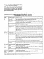
TROUBLE SHOOTING GUIDE
OBLEM
POSSIBLE CAUSE(S)
CORRECTIVE
_]ine will not
nk
Safety switch button
not depressed
There are two switches in the starting circuit of your unit: the clutch pedal switch and the deck lift lever
switch. Make certain the actuator is fully depressing the buttons on each switch.
Battery installed
incorrectly
The battery must be installed with negative terminal attached to black ground wire. Negative terminal
is identified at the post by "NEG", "N" or "-". The positive terminal, identified by "POS", "P" or "+", must
be attached
Battery is dead or weak
ACTION
to the big red wire which goes to the solenoid.
Check fluid level in battery. If fluid is low, fill between
maximum
and minimum
fill lines with water.
Charge with 6 amp charger until fully charged.
Blown fuse or circuit
breaker
Replace fuse with automotive type fuse. Fuses seldom fail without a reason. The problem must be
corrected. Check for loose connections in the fuse holder. Replace fuse holder if necessary. A dead
short may be in the cranking or charging circuit where the insulation may have rubbed through and
exposed the bare wire. Replace the wire or repair with electrician's tape if the wire strands have not
been damaged.
Note: Look for a wire pinched between body panels, burned by the exhaust pipe or muffler or rubbed
against a moving part.
igine cranks
it will not start
Throttle or choke not in
Check owner's guide for correct position for throttle control and choke for starting.
starting position
No spark to spark plug
Spark plug lead disconnected. Connect lead. Place spark plug lead away from engine block about
1/8". Crank engine. There should be a spark. If not, have engine repaired at authorized engine service
dealer.
Faulty spark plug. To test, remove spark plug. Attach spark plug lead to spark plug. Ground the spark
plug body against the engine block. Crank the engine. The spark plug should fire at the electrode.
Replace if it does not.
No fuel to the carburetor
Gasoline tank empty. Fill.
Fuel line or in-line fuel filter plugged. Remove and clean fuel line. Replace filter if necessary.
Air filter dirty
If the air cleaner
manufactu rer.
lgine smokes
Engine loses crankcase
vacuum
Dipstick not seated or broken. Replace defective part.
Engine breather defective. Replace.
_cessive
bration
Bent or damaged blade
spindle
Stop engine immediately. Check all pulleys,
damage. Tighten or replace any damaged parts.
Bent blade
Stop engine immediately.
Engine speed low
Speed selection
Blades short or dull
Throttle must be set at full throttle.
ower will not
scharge
"ass or leaves
is dirty, the engine may not start. Clean or replace as recommended
blade adapters,
keys and bolts for tightness
Replace damaged blade. Only use original equipment
blades.
Use lower ground speed. The slower your ground speed, the better the quality of cut.
Sharpen or replace blades (uncut strip problem only).
lcut strips
le above steps fail to correct the problem, take the unit to your local authorized
17
service dealer for repair.
by the engine
and
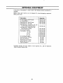
OPTIONAL
At the time of manufacture
available.
EQUIPMENT
{_f lawn tractor, the following optional equipment
NOTE: These lawn tractors are not designed
(tillers, plows, etc.).
for ground-engaging
Description
is
equipment
Model No.
40" Two Stage Snow Thrower
42" Dozer Blad
Mulching Kit fo 38"/42" Deck
Mulching Kit fo 46" Deck
Twin Bag Gras_; Collector for 36", 38"
and 42" Side Discharge Decks
Twin Bag Gras.,; Collector for 46"
Side Dischar _le Decks
Front Counter_ eight
Tire Chains-- 18 x 8.5
18x9.5
20x8
20x10
31 Lb. Wheel V_eights
Gang Reel (Se of three)
38" Lawn Swe_ per
Heavy Duty La_n Roller
Heavy Duty Du np Cart
Tine De-Thatcl" er
*Available through your Ioca dealer or from Agri-Fab
Street, Sullivan, Illinois 6195f.
18
190-621-000
190-620-000
190-112-000
190-118-000
190-063-000
190-103-000
190-745-000
190-754-000
190-657-000
190-658-000
190-915-000
190-215-000
45-0195"
45-0222*
45-0179"
45-0171"
45-0186"
Inc., 303 W. Raymond
USE THIS PAGE AS A GUIDE TO DETERMINE
SLOPES WHERE YOU MAY NOT OPERATE SAFELY,
SIGHT AND HOLD THIS LEVEL WITH A VERTICAL TREE
A POWER POLE
°oo
o
L_Ln
T"-
L_Ln
15 °
Ge._a_4_q_4_4_4_t
WA RNiN
_AA_AAAAA
VVT_VVVV_
Do not mow on inclines with a slope in excess of 15 degrees (a rise of approximately 2-1/2 feet every 10 feet). A
riding mower could overturn and cause serious injury, If operating a walk-behind mower on such a slope, it is
extremely difficult to maintain your footing and you could slip, resulting in serious injury.
Operate RIDING mowers up and down slopes, never across the face of slopes.
Copy the information
from
your model plate here:
(Located
%
Under The Seat)
N[]INSININININSININ
Haveyour YO_./
iP
modelnumber
available
whenyoucall
Control Wire 18.5"
'37-0208
'46-0501
Control Wire 35" Lg.
'46-0634
Drive Belt
DECK 38": Blades
V-Belt (Deck)
Grass Collector+
731-0484A
Front Hub Cap (Black)
V-Belt/Deck, Electric PTO
Grass Collector+
DECK 46": V-Belt
+
Rear Wheel Cover (Gray)+
73 _-1615A
Front Wheel Bearings
Bearinqs
Fuse 7.5 AMP
Fuse 20 AMP
741-0487A (4)
7_ 1-0569
'25-1625
'25-1381
7_ 5-0963
7:4-0973
' '25-0201
(Plastic !
(Ball Bearin,qs)
Head Lamp Bulbs
Deck Wheel 5"+
Ignition Key
Illustrated Parts List
V-Belt (Deck)--Lower
Outer Blades (2)
Center Blade
Grass Collector+
38"/42" Mulchinq Kit+
46" Mulchinq Kit+
+ Optional
754-0441
742-0610
754-043
190-063-000
754-O373
190-063-000
754-0439
754-0440
742-0644
742-0645
190-103-000
190-112-000
190-118-000
Order by Complete M( del Number
For Partls,
Accessc
Jrtes or Service
Information,
CJUI NOWI
I (8001) 800-7310
The only way to ensure the performance
is to use original
MTD designs
specifications.
I_
equipment
parts
of your product
and
accessories.
and engineers quality parts to exacting
When you substitut3, you take a chance
on quality, reliability,
original equipment,
safety and performance.
the best bu! on the
Landscape--American
Made and American
WARNING"
Use MTD
American
Owned!
California
c3use cancer,
birthproduct
defects contains
or other chemicals
reproductiveknown
harm.
The Engineto E:chaust
from this
to the State of
I