1
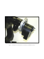
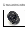
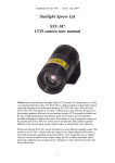
TECHNICAL MANUAL FOR
THEORY OF OPERATION AND OPERATING PROCEDURES
INCLUDES THE NEW PYXIS 3-INCH
OPTEC, Inc.
OPTICAL AND ELECTRONIC PRODUCTS
[email protected]
http://www.optecinc.com
199 Smith St.
Lowell, MI 49331
U.S.A.
(888) 488-0381
(616) 897-9351
(616) 897-8229 FAX
Figure 1-1. Prototype Pyxis system mounted on a TCF-S focuser with SBIG ST-9 Camera.
TABLE OF CONTENTS
November 2006
Section
1.0
2.0
Introduction . . . . . . . . . . . . . . . . . . . . . . . . . . . . . . . . . . . . . . . . . . . . . . . . .
..
Theory of Operation . . . . . . . . . . . . . . . . . . . . . . . . . . . . . . . . . . . . . . . . . . .
.2.1
. . . . .Basic Physical Characteristics . . . . . . . . . . . . . . . . . . . . . . . . . . . . . . .
.
2.2 .Basic
Operation . . . . . . . . . . . . . . . . . . . . . . . . . . . . . . . . . . . . . . . . . .
2.3 .Position Angle . . . . . . . . . . . . . . . . . . . . . . . . . . . . . . . . . . . . . . . . . . .
2.4 .Alt-Azimuth Compensation . . . . . . . . . . . . . . . . . . . . . . . . . . . . . . . . .
.
Page
1
4
4
4
8
8
3.0
Installation & Operating Procedures . . . . . . . . . . . . . . . . . . . . . . . . . . . . . . .
.3.1
.. . Installation of Pyxis . . . . . . . . . . . . . . . . . . . . . . . . . . . . . . . . . . . . . . .
3.2 .Installation of Pyxis 3-inch . . . . . . . . . . . . . . . . . . . . . . . . . . . . . . . . . .
10
10
11
4.0
PC Serial Interface and Commands . . . . . . . . . . . . . . . . . . . . . . . . . . . . . . . .
.4.1 PC (RS-232) Serial Communications . . . . . . . . . . . . . . . . . . . . . . . . .
4.2 .Connecting the Pyxis to the PC . . . . . . . . . . . . . . . . . . . . . . . . . . . . . .
4.3 .Communications Protocol . . . . . . . . . . . . . . . . . . . . . . . . . . . . . . . . . .
4.4 .Pyxis Control Program . . . . . . . . . . . . . . . . . . . . . . . . . . . . . . . . . . . .
..
Trouble-Shooting Guide . . . . . . . . . . . . . . . . . . . . . . . . . . . . . . . . . . . . . . . .
. .. . . .
Specifications for Pyxis . . . . . . . . . . . . . . . . . . . . . . . . . . . . . . . . . . . . . . . . .
Specifications for Pyxis 3-inch . . . . . . . . . . . . . . . . . . . . . . . . . . . . . . . . . . . .
12
12
12
13
17
5.0
6.0
18
19
20
APPENDICES
A
B
Circuit Board Layout for Pyxis. . . . . . . . . . . . . . . . . . . . . . . . . . . . . . . . . . .
A-1
Circuit Board Layout for Pyxis 3-inch . . . . . . . . . . . . . . . . . . . . . . . . . . . . . .
A-2
Circuit Diagram for Pyxis . . . . . . . . . . . . . . . . . . . . . . . . . . . . . . . . . . . . . . .
B-2
Circuit Diagram for Pyxis 3-inch . . . . . . . . . . . . . . . . . . . . . . . . . . . . . . . . . .
B-3
i
LIST OF FIGURES
Figure
1-1
Page
Cover
1-2
Pyxis system mounted TCF-S focuser with SBIG camera . . . . . . . . . . . . .
.Pyxis System Components . . . . . . . . . . . . . . . . . . . . . . . . . . . . . . . . . . . . .
1-2a
.Pyxis 3-inch Camera Side View . . . . . . . . . . . . . . . . . . . . . . . . . . . . . . . . .
3
2-1
6
2-1a
Pyxis Field Rotator Assembly . . . . . . . . . . . . . . . . . . . . . . . . . . . . . . . . . .
.Pyxis 3-inch Rotator Assembly . . . . . . . . . . . . . . . . . . . . . . . . . . . . . . . . .
7
2-2
Pyxis Camera Field Rotator T-thread Side . . . . . . . . . . . . . . . . . . . . . . . . .
6
4-1
PC to Pyxis Serial Cable . . . . . . . . . . . . . . . . . . . . . . . . . . . . . . . . . . . . . .
.Pyxis Control Program Screenshot . . . . . . . . . . . . . . . . . . . . . . . . . . . . . .
12
4-2
2
17
.
LIST OF TABLES
Table
4-1
Page
Serial Mode Command Check . . . . . . . . . . . . . . . . . . . . . . . . . . . . . . . . . .
.Command
.
to find Finds PA 0 . . . . . . . . . . . . . . . . . . . . . . . . . . . . . . . . .
13
Setting Default Direction . . . . . . . . . . . . . . . . . . . . . . . . . . . . . . . . . . . . . .
.Reading
.
the Default Direction Flag . . . . . . . . . . . . . . . . . . . . . . . . . . . . . . .
14
.Retrieve
.
Current Position Angle . . . . . . . . . . . . . . . . . . . . . . . . . . . . . . . . .
.Command to Rotate to a New Position Angle . . . . . . . . . . . . . . . . . . . . . . .
14
.Command to Power Down the Stepper Motor . . . . . . . . . . . . . . . . . . . . . .
.Command to Wake Up the Pyxis . . . . . . . . . . . . . . . . . . . . . . . . . . . . . . . .
15
16
4-10
.Command to Rotate by Small Steps . . . . . . . . . . . . . . . . . . . . . . . . . . . . . .
.Command to Change the Rotational Rate . . . . . . . . . . . . . . . . . . . . . . . . . .
4-11
.Command to Select Full or Half Step . . . . . . . . . . . . . . . . . . . . . . . . . . . . .
16
4-2
4-3
4-4
4-5
4-6
4-7
4-8
4-9
ii
13
14
15
15
16
SECTION 1.0
INTRODUCTION
The rapid expansion of robotic telescope and observatories has created a need for many devices
that enhance the operation of these facilities with regards to remote and unattended operation. In
recent years, robotic telescope mounts, PC controlled focusers, filter wheels, dome controls, CCD
camera with elaborate scripting functions and internet access has made possible, to the small
observatory, sophisticated automated functions at low cost. Optec Incorporated supplies many of
these devices and has now designed the Pyxis camera field rotator.
Many of the SBIG line of CCD cameras feature an off-axis guide chip. These guide chips are
usually small and it is sometimes difficult to acquire a sufficiently bright guide star for some
objects. Having the ability to rotate the camera allows another degree of freedom and increases
the probability to find a suitable guide star. Many of the camera control programs with star atlas
have overlay reticules for both the imaging chip and guide chip. The position angle of these
reticule overlays can be read out and used as an input value to the Pyxis. The Pyxis will
immediately rotate to the desired position angle. It is hoped for and expected that many of the
camera control programs will incorporate the Pyxis control codes into their programs making the
job of rotation that much more convenient.
For alt-azimuth mounts, it is impossible to take long exposures without the ability to compensate
for the rotation of the camera field. This rotational rate is very non-linear and is a function of the
altitude and azimuth of the star, and the latitude of the observer. The Pyxis offers the ability to
correct for this field rotation by rotating the camera in the opposite direction for as long as the
exposure is in process. When starting an exposure, the observer only has to input to the Pyxis
control software the right ascension and declination of the observed object.
The Pyxis is compatible with the Optec Next Generation Telecompressors including the
MAXfield 0.33X and the WideField 0.5X. It will fit the Model TCF-S Temperature Compensated
Focuser or any other high quality 2-inch mount as standard. Adapters are available to fit a wide
variety of telescopes and cameras.
In 2006, the Pyxis 3-inch was introduced with a clear aperture of 3 inches and much greater load
bearing capacity. This model supplements the new TCF-S3 which also has a clear aperture of 3
inches. Similar in concept and operating protocol, the Pyxis 3-inch can be substituted in place of
the Pyxis when the need for larger cameras or instrument packages are required. This model is
intended for large observatory mounted telescopes.
1
Figure 1-2. Pyxis System Components.
2
Figure 1-2a. Pyxis 3-inch Camera Side View.
3
SECTION 2.0
THEORY OF OPERATION
2.1 BASIC PHYSICAL CHARACTERISTICS
The Pyxis camera field rotator is comprised of a fixed circular plate that is attached to the
telescope’s focusing mount and a rotating plate that is attached to the CCD camera or other
imaging device. A stepper motor with drive gear rotates the plate attached to the CCD through
360 degrees in 1 degree steps when used to find position angle. The total gear reduction is 110 :
1. Combined with the 48 steps per revolution of the stepper motor drive shaft, one complete
revolution of the camera takes a total of 5280 steps. Thus, each step from the motor rotates the
main drive gear holding the camera by about 4 arc minutes.
The Pyxis 3-inch is similar in concept but uses a large 6-inch diameter bronze worm gear and
stainless steel worm. The 360 tooth worm gear is cut “double start” which makes the effective
number of teeth equal to 180. An 9 tooth spur gear on the motor shaft drives a 48 tooth gear on
the worm shaft. This results in a total gear reduction to complete one revolution taking 46080
steps. Each step is thus equal to 0.469 arc minutes.
Only two cables are required to operate the Pyxis or Pyxis 3-inch. The first one is a low voltage
12 VDC cable with 2.5 mm power plug to supply operating power and the other is a 6-conductor
RJ-12 cable for connection to a PC or laptop computer. The Pyxis needs a computer for proper
operation and cannot be operated in a stand-alone mode.
The Pyxis with T-mount and telescope adapter weighs 27 ounces. The approximate dimensions
of the unit without adapters are 6-inches in diameter and 1.5-inch thick. See Figure 2-1 for an
assembly and cross sectional view of the Pyxis.
The Pyxis 3-inch uses the same adapters as the TCF-S3 for connecting to the telescope or to the
camera. This model is not compatible with any of the camera side adapters used for the smaller
Pyxis. The approximate dimensions of the unit without any adapters is 6.4 X 7.5 X 2.4 inches and
weighs 4.5 pounds. See Figure 2-1a
4
2.2 BASIC OPERATION
When first activated, the Pyxis or Pyxis 3-inch rotates HOME to find the 180 degree position
angle point which is detected with a magnet mounted in the rotating main drive gear and a Hall
effect sensor mounted in the circuit board. Once the magnet is found, the unit reverses direction
and rotates to the 0 degree position angle. The Pyxis will not accept any commands until the 0
degree position angle is obtained. If the unit fails to home properly, an error code is sent on the
serial cable to the operating PC and the unit will stop to wait for additional commands.
A small red LED indicates that the circuit is powered on when illuminated. In the SLEEP model,
the LED will flash at a steady rate. See the Pyxis.exe control program HELP file for more
information about the SLEEP mode.
The main gear of the Pyxis rotates with a rated torque of 13 inch-pounds. This degree of torque
should be adequate to handle most of the common CCD cameras from SBIG and others.
However, if the camera is severely off-balanced or cables to the camera are snagged, the main
drive gear will slip. No damage to the unit is possible but the position angle will be lost and the
Pyxis would have to be homed again.
Because the stepper motor operates in a pulse fashion, there is a considerable amount of gear
chatter when the Pyxis is rotating to a new position angle. While disconcerting to listen too, this
chatter is normal to the operation of the unit. The degree of chatter is a function of the motor
speed. At the default pulse delay of 8 milliseconds (nn = 08), the chatter is minimized. This
variable can be changed with CTxxnn command (see Table 4-9) to allow for other rotational
rates. The new delay variable entered in this way is stored in EEPROM. Some caution should be
exercised to avoid using very long delays since the Pyxis will have to finish homing or moving to a
new position angle before any new delay variable can be entered.
Since the Pyxis 3-inch uses a worm gear, the chatter mentioned above is barely perceptible and
the default settings for pulse delay of 6 should be kept. However, if the instrument package is
well balanced, it may be possible to decrease the pulse delay in order to increase the rotational
rate. Lower pulse delay numbers will decrease running torque which may result in lost steps.
Because of the increase in torque for the Pyxis 3-inch care should be taken to prevent cables
going to the instruments from becoming snagged. Since this model uses a worm gear instead of
the spur gear, the stepper motor is powered off when the unit is not rotating. This reduces
considerably the power requirements and the resulting heating of the unit. In the idle state, the
Pyxis 3-inch uses less than 0.1 amps.
5
Figure 2-1. Pyxis Field Rotator Assembly.
6
Figure 2-1a. Pyxis 3-inch Field Rotator Assembly.
7
2.3 POSITION ANGLE
The common way to measure position angle in the sky is to start at north at 0 degrees and rotate
clockwise (abbreviated CW) through East (90 degrees PA), South (180 degrees PA), West (270
degrees PA) and back to North for a full 360 degrees. When using a telescope, the apparent
rotation of the camera may be opposite when compared to the rotational direction in the sky. For
this reason, it may be necessary to reverse the default direction. This can be done in the setup
menu of the Pyxis control program or by using the CDnxx command described in Table 4-3.
Refractors and Cassegrain telescopes have the same apparent direction of field rotation.
Newtonians, on the other hand, are opposite. Depending on the number of reflections in the
telescope system, the default or reverse direction may have to be selected in order for the
rotational direction to match the sky. Trial and error may be necessary.
Once the proper default direction for rotation is obtained, the desired position angle can then be
achieved. For position angle, the Pyxis will only accept integer entries from 0 to 359 degrees.
Since there are 14.6 steps (128 steps for the Pyxis 3-inch) for each degree, there is a small round
off error of 0.5 steps maximum for each degree interval. This translates to a maximum error for
any position angle of 2 (0.6 for the Pyxis 3-inch) arc minutes. This value does not take into
account any gear backlash, which may be on the same order in magnitude.
The new position angle can be entered in either the Pyxis control program or by using the
CPAxxx command described in Table 4-6. At the default pulse delay of 8, it takes approximately
120 milliseconds for the Pyxis to rotate 1 degree. The default pulse delay for the Pyxis 3-inch is
6, which results in a rotational rate of 785 milliseconds per degree. During the rotational time, the
Pyxis cannot accept any commands until the move is completed. If the camera were tugging at
cables or mechanically obstructed for some other reason, it would be necessary to cut power in
order to abort the move. As mentioned before, the Pyxis will not be damaged if the rotational
movement is blocked. However, the user should use care and common sense with attached
cameras and cables to ensure they will not be damaged. When used in position angle mode the
rotator will never pass PA=180 degrees to avoid wrapping or twisting any attached cables.
2.4 ALT-AZIMUTH COMPENSATION
Alt-Azimuth mounts from some makers may have the ability to track celestial objects with
sufficient accuracy for imaging. The Pyxis has the ability to correct for field rotation that is the
undesired consequence of using an alt-azimuth mount with a camera. Normally, field rotation will
be a problem for any exposure over a minute in length. This depends greatly on the users latitude
and position of the object in the sky. Because the correcting rotation rate increase very
dramatically near the zenith, the Pyxis control program will not accept values greater than 80
degrees to zenith.
8
The Pyxis control program makes the necessary calculations for obtaining the rotational rate and
sends the appropriate codes to the Pyxis. The actual calculations are extensive and are not
presented in this manual. For the programmer interested in correcting field rotation, see the
CXxxnn command described in Table 4-9.
Figure 2-2. Pyxis Camera Field Rotator T-thread Side.
9
SECTION 3.0
INSTALLATION & OPERATING PROCEDURE
3.1 INSTALLATION OF PYXIS
The Pyxis rotator is shipped with a detachable 2” nosepiece. Power is provided by a 12 VDC
switching power supply that can accept 110VAC to 230 VAC input. A 6-wire Reverse cable and
serial port converter connect the Pyxis to the user’s PC for computer control of the rotator.
Camera adapters need to be purchased separately.
To install the Pyxis rotator to a standard T-thread camera such as the SBIG ST-X series cameras,
simply screw the camera onto the male T-thread on the back of the Pyxis. Three small setscrews
allow rotational adjustment for the camera. Use the .050” long arm L-shaped ball driver to
carefully loosen and tighten the setscrews. For non-T-thread cameras other mounts are available.
Contact Optec to specify C-mount or SCT (2” 24tpi) threaded mounts.
Once the camera is attached, the Pyxis and camera can be inserted into any 2” focuser. There is a
small, machined brass screw on the flange of the 2” nosepiece that is designed to drop into a slot
on the Optec TCF-S focuser or the JMI NGF-s focuser. Once the position angle is established
the entire Pyxis can be rotated by carefully loosening the three setscrews holding the 2” nosepiece
in place. Use the 5/64” ball driver to loosen and tighten the three setscrews in the main body of
the Pyxis. After the Pyxis software has initialized, the position angle will be at zero. Adjust the
2” nosepiece to line up with north by examining images with the camera control software.
The detachable 2” nosepiece can also be replaced with either of the Optec NextGEN
telecompressors. The 0.33X NextGEN MAXfield (NGM) can be used with cameras having
diagonals up to 11mm diagonal. The 0.5X NextGEN WideField (NGW) can be used with
cameras having diagonals up to about 18mm. To install either the NGM or NGW, simply loosen
the three setscrews in the main body of the Pyxis and remove the standard 2” nosepiece. Install
the telecompressor in its place. The back focus distance is set for proper operation with the SBIG
ST-X line without the need for a separate camera mount. Contact Optec for using the NGM or
NGW with the Pyxis and other cameras.
To connect the Pyxis to your Windows PC, you should order the #17695 Serial Port Converter
and a Reverse cable of proper length. Figure 4-1 shows the proper pins to connect for the cable
and converter for users wishing to fabricate their own cable.
Install the software as described in Section 4.0 below. All Pyxis operational commands are
provide through software.
10
3.2 INSTALLATION OF PYXIS 3-INCH
To attach the Pyxis 3-inch to the telescope, one of the TELESCOPE MOUNTS for TCF-S3 or
Pyxis 3-inch is needed. The most current selection is listed in the Optec price list. At this time,
mounts are available for:
17801
17802
17803
17808
17809
Meade Telescope for 4” Rear Cell Thread - LX200 16” telescope
Meade Telescope for 3” Read Cell Thread – most mid size telescope
Celestron Telescope for 3” Rear Cell Thread -11” and larger sizes.
AstroPhysics 2.7” mount
Takahashi 2.8” mount
Attach the telescope mount first to the telescope and then add the Pyxis 3-inch. Secure at the
proper rotation angle by tightening the three #10 setscrew in the front with the supplied allen hex
key. Tighten the screws evenly so that the face of the Pyxis is flush with the shoulder of the mount
and no air gap is seen. When the Pyxis 3-inch is turned on, it will rotate to position angle 0.
The camera side of the Pyxis presents a 3-inch I.D. port. This is currently a non-standard size for
telescopes so an Optec adapter to fit various cameras or other devices is needed. At this time,
adapters are available for:
17804
17805
17806
17807
3” to 2” reducer bushing to allow any standard 2” diameter accessory to be inserted.
3” to Optec IFW filter wheel mount
3” to STL camera mount that fits the 4-bolt pattern on the STL camera from SBIG
3” to AstroPhysics 2.7” mount.
Check with the current price list or Optec web site for an up-to-date listing of available telescope
adapters and camera side mounts.
Make sure that there is enough cable slack for the attached instruments to allow for
rotation. The torque of the Pyxis 3-inch is sufficient to pull out cables which may do
damage to your equipment. After finding the 0 position angle, the Pyxis 3-inch will not
rotate anymore than ±180 degrees from the 0 position angle.
To connect the Pyxis 3-inch to your Windows PC, you should order the #17695 Serial Port
Converter and a Reverse cable of proper length. Figure 4-1 shows the proper pins to connect for
the cable and converter for users wishing to fabricate their own cable.
Install the software as described in Section 4.0 below. All Pyxis operational commands are
provide through software.
11
SECTION 4.0
PC SERIAL INTERFACE AND COMMANDS
4.1 PC (RS-232) SERIAL COMMUNICATIONS
The Pyxis system provides a serial communications feature as standard. Using simple ASCII
commands, both modules can be programmed with certain variables that are stored in the
microcontroller EEPROM. The RS-232 interface operates at 19.2 K baud with 8 data bits, one
stop bit and no parity.
Optec has developed a user interface program called Pyxis.exe that will interface with the
instrument and allow the operational variables to be set.
4.2 CONNECTING THE PYXIS TO THE PC
A cable with a 6-pin modular connector on one end and a 9-pin sub-D connector on the other is
used to connect a PC to either module. Figure 4-1 shows the pin-to-pin connection for the
interface cable. Optec’s implementation is in two parts: the #17695 Serial Port Converter
attaches directly to the DB9 serial port on the PC, and a flat 6-wire Reverse cable up to 50’ in
length connects the serial port converter to the Pyxis rotator. These items are identical to the
serial connections used with the TCF-S/TCF-S3 focuser and IFW filter wheel.
Figure 4-1. PC to Pyxis serial cable.
12
4.3 COMMUNICATIONS PROTOCOL
The remote PC communication program should be set for 19.2 K baud rate with 8 data bits, 1
stop bit, and no parity (8N1). The Pyxis is preset for these values and will not respond to other
settings and cannot be changed. Tables 4-1 through 4-7 below describe in detail the commands
used to control and communicate with the Pyxis. To establish communications with the Pyxis,
plug in the power supply and wait for the Pyxis to complete the homing routine. Once the homing
routine is complete, the unit will enter the serial loop function and await commands from the PC.
To verify that the Pyxis is in the serial loop, send the CCLINK command which the Pyxis will
reply with a “!” LF CR. In the tables below, the commands comprise upper case letters as shown.
The small case n represents any number from 0 to 9. The small case x represents any character
since they are ignored. LF represents the line feed control character 0A hex. CR represents the
carriage return control character 0C hex. It is necessary to send the command as one data stream
with normal pacing between characters. Typing in the characters one at a time with a terminal
program will not work.
Command
Return
CCLINK
! CR LF
Function:
This command checks to see if the Pyxis is in the serial loop mode. A successful return
from this command (!) is required before the Pyxis will accept any other user commands.
Trouble Shooting:
If “!” is not returned check to see if the Pyxis has completed its homing routine. Check
baud rate and serial connection.
Table 4-1. Serial mode command check.
Command
Return
CHOMES
! (for every step made)
F (when homing is compete)
Function:
This commands the Pyxis to rotate and find the home position magnet and then return to
position angle 0.
Trouble Shooting: An ER=1 is returned if the magnet cannot be found. This might happen
if the unit is jammed and cannot rotate properly.
Table 4-2. CHOMES Command finds PA (position angle) 0.
13
Command
Return
CDnxxx
(no return characters)
Function:
This command sets the default direction either CW or CCW for proper rotation with
regards to position angle in the sky. Enter 0 for n to rotate in the default direction or 1 to
rotate in the reverse direction. The star fields of Refractor and Newtonian telescopes are
mirrored with respect to each other. Match your sky atlas and camera control program
position angle to the Pyxis. The value is stored in the Pyxis EEPROM.
Trouble Shooting:
Table 4-3. Setting default direction.
Command
Return
CMREAD
n CR LF (n can be either 0 or 1)
Function:
This command reads the stored default direction flag from the Pyxis EEPROM. The
default value from Optec is 0.
Trouble Shooting:
Table 4-4. Reading the default direction flag.
Command
Return
CGETPA
nnn CR LF (nnn can have integer values from 000 to 359)
Function:
This command retrieves the current position angle in degrees from the Pyxis. Only integer
values from 000 to 359 are returned. A zero degree value normally is the direction to
North, 90 degrees is to the East, 180 degrees is to the South and 270 degrees is to the
West.
Trouble Shooting:
Table 4-5. Retrieve current position angle.
14
Command
Return
CPAn1n2n3
! (for every step made)
F (when motion is complete)
Function:
The new position angle is entered as nnn for any integer value from 000 to 359. Note that
left justified zeros are necessary for the entry. For example: to move to 10 degrees PA,
enter CPA010.
Trouble Shooting:
An error code 3 is returned if the position angle entered is over 359. If the entered
position angle is equal to the current, and error code 2 is returned.
Table 4-6. Command to rotate to a new position angle.
Command
Return
CSLEEP
(no return characters)
Function:
This command turns off power to the stepper motor. During the sleep state, the red LED
on the Pyxis will flash slowly. All operating parameters are kept in memory and are
available when the Pyxis is awakened. Once in SLEEP, the control program will ignore all
commands except the CWAKUP command.
Trouble Shooting:
With power off to the motor, the unit can be rotated by hand if enough torque is exerted to
overcome the static friction. The current position angle can be lost if the camera is not
properly balanced around the optical axis. Homing the Pyxis will return the unit to a
known position angle.
Table 4-7. Command to power down the stepper motor.
Command
Return
CWAKUP
“!” CR LF
Function:
This command powers on the stepper motor and returns the Pyxis operating program to
the serial loop. This command is only recognized when the Pyxis is in the SLEEP mode.
Table 4-8. Command to wake up the Pyxis.
15
Command
Return
CXxxn1n2
“!”
Function:
This command will rotate the Pyxis in the direction specified by n1 by n2 number of steps.
n2 can be any value from 1 to 9 and n1 can be either a 0 or a 1. Position angle information
is not updated when this command is used
Trouble Shooting:
If this command is used, the value for the current position angle will be in error. The Pyxis
will have to be homed in order for the position angle to be found again.
Table 4-9. Command to rotate by small steps.
Command
Return
CTxxn1n2
“!”
Function:
This command controls the rotational rate of the Pyxis. The value of n1n2 can be any
integer value from 00 to 99 with 08 being the default rate. This value is used as a delay
parameter in milliseconds within the stepper motor control routine.
Trouble Shooting:
If a large value is entered, the Pyxis may take a very long time to complete a position angle
change or home itself. It would be necessary to wait before entering a new value.
Table 4-10. Command to change the rotational rate.
Command
Return
CZnxxx
(no return characters)
Function:
This command selects either full step or ½ step rates for the Pyxis. The value of n can be
either 0 for full step or 1 for ½ step. The default value is 0. The advantage of ½ step rate
is less vibration at the expense of speed.
Trouble Shooting:
The ½ step rate will slow the stepper rotation rate by ½ for the same delay value selected
with the CT command. This command is only available for firmware 1.10 and above
Table 4-11. Command to change the step mode.
16
4.4 PYXIS CONTROL PROGRAM
Included with the Optec CDROM distribution software is a control program that will operate the
Pyxis and allow for the controlling variables to be changed. The latest version of the control
program can be found on the Optec website at www.optecinc.com. Look for the Software
Download page in the Pyxis section. This program is self-extracting and will install all needed
components when the file is opened. The operating program will load a short cut into your
START MENU that can be noted by the Pyxis icon. A README file, which notes any new
information, can also be accessed and viewed in the START MENU. Once installed, consult the
HELP menu selection in the program to obtain program setup and operating information.
To operate the Pyxis 3-inch, it is necessary to have version 1.20 or above. Select the model type
in the Setup pull-down menu. The only function that is affected by this is the alt-azimuth routine.
The Pyxis 3-inch has smaller step angles for increased precision when used for de-rotation
control. Earlier versions of the control program will operate the Pyxis 3-inch except for derotation where there would be an error in the rotation rate.
Other software writers for telescope/CCD control applications have incorporated the Pyxis into
their code. For short descriptions and links to these third party software sources, see
http://optecinc.com/optec_069.htm.
Figure 4-2. Pyxis Control Program screenshot.
17
SECTION 5.0
TROUBLE-SHOOTING GUIDE
Contact Optec technical support for trouble-shooting any problems with the Pyxis camera field
rotator.
1) A serial connection to the Pyxis with a USB-to-Serial converter can sometimes be frustrating.
We have found that those converters using the FDIC chip set are the most compatible. The
Pyxis.exe control software will not work with converters using the Prolific chipset. However,
3rd party software may be compatible with the Prolific chipset. The converters sold by Optec
use the FDIC chipset. In order to see if the problem is with the USB-to-Serial converter, it is
suggested that the Pyxis be used with a computer having a native COM port with 9-pin
connecter. This would determine if the problem is with the converter or the interface driver on
the circuit board.
2) If wobble affects the camera, the three nylon tipped setscrew may be tightened slightly to
steady the camera. However, it is recommended that these screws only be adjusted by Optec.
These screws are located around the plate on the telescope side and press against the large
gear to remove any play. In addition, these screws are secured with a thread retaining
compound which may make adjusting by the user difficult. A special warning seal tape is
placed over the screws reminding the user that only Optec should adjust them. Over
tightening these screws will lock the gear and the stepper will stall. In extreme case, users
have been known to push the main bearing out causing more extensive repairs.
3) At the current time, there is no commercially available field reducer that is compatible with
the Pyxis (2-inch model) and the AOL or AO-7 from SBIG. The back focus using these
products exceeds the dimensions of any know reducer. Mounting the reducer on the camera
side of the Pyxis will usually vignette the image since the clear aperture of the Pyxis is 1.65
inches. The Pyxis 3-inch is large enough to accommodate the reducer on the camera side and
would be the ideal choice for cameras using the AO-7/AOL with or without field reducers.
4) The Pyxis 2-inch model uses a high torque motor that generates significant amount of heat.
This is normal and the rise in the case temperature is an unfortunate but necessary
consequence. The total amount of heat generated is about 6 watts. The heating can be turned
off by placing the Pyxis in the SLEEP state. This reduces 90% of the power to the unit but
may allow the Pyxis to rotate since the holding torque is cut. For camera systems that do not
add any gravity generated torque to the Pyxis, this may be a way to reduce the heating. In any
case, the 6 watts of heating should be of little consequence. The Pyxis 3-inch uses a motor
that uses only 3.5 watts and the heating effect is much reduced.
18
SECTION 6.0
SPECIFICATIONS for Pyxis
MECHANICAL
Main Gear Diameter
Total Gear Reduction
Number of Steps for One Rotation
Degrees for One Step
Load capacity
4.125 inches
110 : 1
5280
0.0682º (4.09 arc minutes)
5 pounds maximum
MOTOR
Type
Voltage
Steps for One Rotation
Coil Resistance
Bipolar Stepper
12 VDC
48
40 ohms high torque motor with neodymium magnets
MICROCONTROLLER
Type
EPROM
RAM
I/O Lines
EEPROM
Operating Temperature
PIC16CE625
2K x 14
128 x 8
13
128 x 8
-40° to +80° C
POWER REQUIREMENTS
Voltage
Current
Fuse protection
11.7 to 12.3 volts DC
500 ma for high torque motor
0.8 amp, PTC reset able
SIZE & WEIGHT
Size
Clear Aperture
Weight
6 inches diameter x 1.5 inches thick without adapters
1.65 inches
27 ounces with adapters
INCLUDED ITEMS
Adapters
Power Supply
Tools
Software
2” telescope detachable adapters
12 VDC regulated power supply with 6’ cords
5/64” and 0.05” hex keys
CD disk with Pyxis control software and manual
19
SPECIFICATIONS for Pyxis 3-inch
MECHANICAL
Main Gear Diameter
Total Gear Reduction
Number of Steps for One Rotation
Degrees for One Step
Load Capacity
5.625 inches, 360 teeth double start, 64 pitch
960 : 1
46080
0.0078125º (0.46875 arc minutes)
20 pounds maximum
MOTOR
Type
Voltage
Steps for One Rotation
Coil Resistance
Bipolar Stepper
12 VDC
48
40 ohms high torque motor with neodymium magnets
MICROCONTROLLER
Type
EPROM
RAM
I/O Lines
EEPROM
Operating Temperature
PIC16F87
4K x 14
368 x 8
16
256 x 8
-40° to +80° C
POWER REQUIREMENTS
Voltage
Current
Fuse protection
11.7 to 12.3 volts DC
400 ma for high torque motor running
0.8 amp, PTC reset able
SIZE & WEIGHT
Size
6.5 inches wide x 7.45 inches height and 2.4 inches
thick without adapters
3.00 inches
4.5 pounds without adapters
Clear Aperture
Weight
INCLUDED ITEMS
Adapters
Power Supply
Tools
Software
optional
12 VDC regulated power supply with 6’ cords
Various hex keys
CD disk with Pyxis control software and manual
20
Appendix A
CIRCUIT BOARD LAYOUT
Pyxis Circuit Layout
A-1
Pyxis 3-inch Circuit Layout
A-2
Appendix B
CIRCUIT DIAGRAM
B-1
B-2
B-3