1
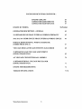
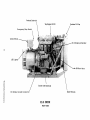
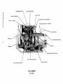
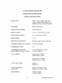
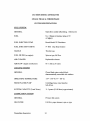
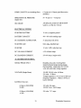
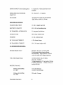
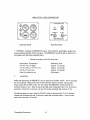
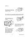
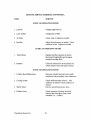
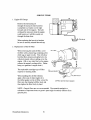
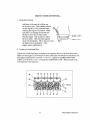
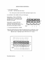
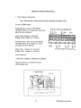
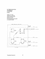
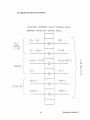
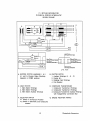
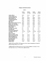
OPERATIONS & MAINTENANCE
MANUAL
WESTERBEKE
DIESEL GENERATORS
MOBILE & INDUSTRIAL
MODEL 15.0 BTDAR, 20.0 BEDR,
25.0 BEDR & 32.0 BEDR
60 HERTZ
MODEL 12.0 BTDAR, 16.0 BEDR,
20.0 BE DR, 25.0 BEDR
50 HERTZ
SINGLE & THREE PHASE GENERATORS
Publication # 039835
Edition Two
May 1993
~r-.v- 'WESTERBEKE
~
WESTERBEKECORPORATION
MYLES STANDISH INDUSTRIAL PARK
150 JOHN HANCOCK ROAD, TAUNTON, MA 02780-7319
INTRODUCTION
Thank you for purchasing a Westerbeke diesel generator. With proper care on a routine
basis, your Westerbeke generator is designed to provide you with reliable and economical
power for many years.
This manual will help familiarize you with your engine. It covers initial service, operation,
maintenance and troubleshooting in depth.
It also contains important safety information, key specifications, and a wiring diagram.
No manual can provide for every possible question or contingency. If you should need
further assistance, please contact the Westerbeke Master Distributor located nearest you
for technical advice.
Again, thank you for choosing a Westerbeke!
Sincerely,
WESTERBEKE CORPORATION
Westerbeke Generators
ENGINE SERIAL NUMBER LOCATION
The engine serial number and model designation are found on an LD. tag affixed to the
generator's housing. An illustration of this I.D. tag is shown below. Take the time to fill
in the model description, engine serial number and generator serial number in the
appropriate blocks in the illustration below. These will provide quick reference when
ordering spares, repair parts or when seeking technical information.
'~79ELI.
:1.6 .. 0
)0 .. 0
:1.6 .. 0
:I. .. ()
I
~.:jO
:I.
6()
CClN'r ..
220
";"1')
I
..: ..
II
••..,
l
: .:; ::? .. ()
l.;.()
II
0
:I. ~::.i () ()
The engine serial number can also be found stamped into the engine block on a smooth
rectangular surface above the injection pump. The generator serial number is stamped into
the generator housing on the flat surface above the rear generator bearing.
Westerbeke Generators
2
BE SAFETY CONSCIOUS
A careless moment can cause an accident or fire. Here are basic DO's and DON'TS:
DO'S
DON'TS
•
DO visual inspections before
starting your generator.
•
DON'T touch any moving part on
your engine during operation.
•
DO check your engine once a
day. Keep eyes open and be
alert to people and obstacles.
•
DON'T touch hot engine parts such
as exhaust manifolds.
3
Westerbeke Generators
•
•
DO keep fuel away from your engine •
at all times. Check for leaks regularly
and correct them.
DO check the capacity of sling
hoist when lifting the unit. Use
hangers and a wad of cloth in
between sling and unit.
Westerbeke Generators
•
4
DON'T remove radiator filler cap
immediately after shutting down
engme.
DON'T smoke near the battery
Never use an open flame as a
light anywhere on or around the
battery. Battery gas is highly
flammable. Sulfuric acid is
destructive. If it comes in
contact with your skin, wash
it off at once with water.
5
•
DON'T work on an engine while it is
running. If it is necessary to check
the engine while running, use caution
and beware of moving parts and the
presence of AC voltage.
•
DON'T touch AC electrical
connections while the unit is running.
Lethal voltage is present at these
connections.
Westerbeke Generators
NOTES, CAUTIONS AND WARNINGS
NOTES, CAUTIONS, AND WARNINGS are used in this manual to emphasize important
and critical instructions. They are used for the following conditions:
An operating procedure, condition, etc. essential to notate.
CAUTION
Operating procedures, practices, etc. which if not strictly observed, will
result in damage or destruction to your engine.
WARNING
Operating procedures, practices, etc. which if not correctly followed, will
result in personal injury or loss of life.
DEFINITION OF LOCAL TERMS
The words "leftside", "rightside", "front", and "rear" are used in the senses
illustrated below:
Right
Front
( Radiator
End)
0000
Left
Westerbeke Generators
6
Rear
(Generator
End)
TABLE OF CONTENTS
PAGE
GETTING TO KNOW YOUR GENERA TOR
9
SPECIFICATIONS (General and System)
15.0 BTDAR
20.0 BEDR
25.0 BEDR
32.0 BEDR
17
22
27
32
CONTROLS AND INSTRUMENTS
38
NEW GENERA TOR INITIAL INSPECTION
40
DAILY WALK AROUND CHECKS
41
DIESEL FUEL, ENGINE OIL, COOLING WATER
42
OPERA TING YOUR GENERA TOR
44
STARTING
WARMING UP
STOPPING
44
45
45
ROUTINE-SERVICE
GENERAL RULES
SAFETY RULES
SERVICE SCHEDULE
46
46
46
SERVICE ITEMS
50
47
ENGINE OIL & FILTER
CYLINDER HEAD BOLTS AND
VALVE ADJUSTMENTS
15.0 BTDAR & 20.0 BEDR
25.0 & 32.0 BEDR
INJECTOR SERVICING
AIR FILTRATION SYSTEM
FAN BELT
7
50
51,52
52,53
54
54
55
Westerbeke Generators
ENGINE SERVICE ITEMS CONTINUED ...
ENGINE COOLANT
GENERA TOR ADJUSTMENTS
GENERA TOR MAINTENANCE
ENGINE DC WIRING
55
56
57
58,59,60,61
GENERA TOR DESCRIPTION - GENERAL
63
15.0 BTDAR SINGLE PHASE INTERNAL WIRING SCHEMA TIC
65
20.0, 25.0, 32.0 BEDR SINGLE PHASE INTERNAL WIRING SINGLE
66
BTDAR & BEDR INTERNAL WIRING SCHEMA TIC
(THREE PHASE ONLY)
67
VOLTAGE REGULATOR ADJUSTMENTS 20,25,32 BEDR
68
15 BTDAR NO LOAD VOLTAGE ADJUSTMENT
(SINGLE PHASE ONLY)
69
AC VOLTAGE CONNECTIONS-ALL MODELS
70
15 BTDAR OPTIONAL VOLTAGE REGULATOR
(SINGLE PHASE ONLY)
71
ENGINE TROUBLESHOOTING
72
TORQUE SPECIFICATIONS
77,78
Westerbeke Generators
8
Preheat Solenoid
Breaker
Engine Oil Fill
Emergency Shut-off Switch
Speed Sensor
\0
DC Alternator Shield
Circuit Breaker Box
Fan/Belt Guard
:2
(t)
Ul
.....
..,
(t)
0(t)
A C Connections Outlet
Exhaust Manifold
;><;"'
(t)
C)
(t)
::l
..,
(t)
po
.....
o..,
Ul
15.0 BTDAR GENERATOR
RIGHT SIDE
~
-a(I)
Water Temperature Switch
en
( I)
Fuel Filter
(I)
;<;""
(I)
CJ
(I)
Fuel Lift Pump
::l
(I)
-
P.l
o..,
en
Start/Stop Panel
.Radiator _
..
LED Lights
Unit Data Tag
o
DC Battery Ground
Fan I Belt Guard
Starter with Solenoid
Injection Pump
Lube Oil Filter
Oil Pressure Sender
15.0 BTDAR GENERATOR
LEFT SIDE
Preheat Solenoid
/Radia,or Fill Cap
Emergency Stop Switch
;.
~
Control Panel
DC Charging Alternator
-LED Lights
Lube Oil Drain Hose
~
~
~
~
do
~
~
~
::s
DC Battery Ground Connection
~
~
o
..,
en
20.0 BEDR
RIGHT SIDE
Top Engine Oil Fill
~
~
(1)
8-
Filter
Air Intake Silencer
~
Breaker
(1)
o
Fuel Lift Pump
(1)
::l
(1)
g
o..,
en
-
Actuator
Control Panel
AC Connections Outlet
......
tv
. Radiator
Fresh Water Block Drain
Oil Pressure Sender
Lube Oil Filter
Fuel Injection Pump
20.0 BEDR
LEFT SIDE
13
Westerbeke Generators
Westerbeke Generators
14
15
Westerbeke Generators
Westerbeke Generators
16
15.0 BTDAR DIESEL GENERA TOR
SINGLE PHASE & THREE PHASE
GENERAL SPECIFICATIONS
ENGINE TYPE
Diesel, 4 cycle, 4 cylinder, fresh water
cooled. Vertical, in-line overhead valve
mechanism (30 hp at 1800 rpm maximum).
GOVERNOR
Electronic Governing
COMBUSTION CHAMBER
Swirl chamber type.
BORE & STROKE
3.50 x 3.50 inches (88.9 x 88.9 mm)
PISTON DISPLACEMENT
134.8 cubic inches (2.2 liters)
FIRING ORDER
1-3-4-2
DIRECTION OF ROTATION
Clockwise, when viewed from the front
MAXIMUM TORQUE (AT 1800 RPM)
1171b-ft (16.18 kg-m)
COMPRESSION RATIO
21:1
COMPRESSION PRESSURE
(Limit of difference between cylinders)
427 psi (30 kglcm2) at 250 rpm
47.2 psi (3.0 kglcm 2)
VALVE TIMING
Intake Opens 17° BTDC
Intake Closes 47° ABDC
Exhaust Opens 51 ° BBDC
Exhaust Closes 13 ° ATDC
VALVE SEAT ANGLE
Intake 45°
Exhaust 30°
VALVE CLEARANCE
(Engine Cold)
Intake 0.012 inches (0.3 mm)
Exhaust 0.012 inches (0.3 mm)
ENGINE SPEED
1800 rpm 60 Hertz
1500 rpm 50 Hertz
17
Westerbeke Generators
GENERAL SPECIFICATIONS CONTINUED •....
DIMENSIONS
Height: 28.50 inches (723 nun)
Width: 24.8 inches (530 mm)
Length: 49.6 inches (1260 nun)
WEIGHT
870 lbs. (395 kgs)
FUEL CONSUMPTION
2.0 gph (7.571ph) at full rated output
(approximate)
INCLINATION
Continuous 15 0
Temporary 20 0 (not to exceed 20 min)
Westerbeke Generators
18
15.0 BTDAR DIESEL GENERA TOR
SINGLE PHASE & THREE PHASE
SYSTEM SPECIFICATIONS
FUEL SYSTEM:
GENERAL
Open flow, totally self-priming, 1 bleed point
FUEL
No.2 Diesel oil (cetane rating of 45
or higher)
FUEL INJECTION PUMP
Bosch Model VE Distributor
FUEL INJECTION TIMING
0° TDC (Top Dead Center)
NOZZLE
Throttle type
FUEL FILTER (on engine)
Spin-on type, full flow
AIR CLEANER
Replaceable element
AIR FLOW ( engine combustion)
70.0 dIn (l.9 cmm)
COOLING SYSTEM·
GENERAL
Closed fresh water-cooled block,
thermostatically controlled with radiator
OPERATING TEMPERATURE
FRESH WATER PUMP
Centrifugal type, metal impeller,
belt-driven.
SYSTEM CAPACITY (Fresh Water)
11.5 quarts (10.88 liters) approximately
LUBRICATION SYSTEM:
GENERAL
Pressure fed system
OIL FILTER
Full flow, paper element, spin-on type
19
Westerbeke Generators
SUMP CAPACITY (not including filter)
5.3 quarts (5.0 liters) (plus filter/cooler
assembly)
OPERATING OIL PRESSURE
(engine hot)
50 - 65 psi (3.5 - 4.5 kg/cm)
OIL GRADE
API SPECIFICATION OF CF OR CG-4
SAE 30, or 10W-30, 15W-40
ELECTRICAL SYSTEM:
STARTING BATTERY
12 volt 170 A-H, (-) negative ground
(recommended) (200 A-H in cold areas)
BATTERY CAPACITY
400 - 600 cold cranking amps
DC CHARGING ALTERNATOR
51 amp rated, belt driven
STARTING AID
Glow plug, sheathed type.
STARTER
12 volt, 3 KW, reduction type
DC NO-LOAD CURRENT
± 2% of rated Amps
DC CRANKING CURRENT
250-300 amps ( engine cold)
AC GENERATOR GENERAL:
SINGLE PHASE ONLY
Brushless, four pole, revolving field.
Sealed lubricated single-bearing design.
Reconnectable, single phase for 120/240
volts with solid state voltage regulator.
VOLTAGE (Single Phase)
120 OR 120/240 volts- 60 Hertz
220 volts - 50 Hertz
Voltage regulation ± 2% no load to full load
Frequency regulation: .3 Hertz (.005%) no
load to full load.
RATING (Volts AC)
60 Hertz (1800 RPM)
15KW
120 volts 125 amps
120/240 Volts 125/62.5 amps
50 Hertz (1500 RPM)
12KW
220 volts 54.5 amps
Westerbeke Generators
20
GENERATOR COOLING:
250 - 300 cfin (7.08 - 8.5 cmm)
AIR REQUIREMENTS
60 Hertz at 1800 rpm
NOTE: Increase air supply 15% for 50 hertz operation (1500 rpm)
AC GENERATOR GENERAL:
THREE PHASE ONLY
Brushiess, six pole, revolving field.
Sealed lubricated single-bearing design.
12 lead reconnectable for low voltage WYE,
high voltage Delta. Solid State voltage
regulator with protection circuitry.
Voltage - 3 Phase (60 Hertz)
Low voltage WYE
High voltage WYE
DELTA
208 volts
480 volts
240 volts
Voltage - 3 Phase (50 Hertz)
High voltage WYE
DELTA
380 volts
220 volts
Amperage - 3 Phase (60 Hertz)
.8 Powerfactor
Low voltage WYE
High voltage WYE
DELTA
52.1 Amps
22.1 Amps
45 Amps
Amperage - 3 Phase (50 Hertz)
.8 Powerfactor
High voltage WYE
DELTA
22.8 Amps
39.4 Amps
TUNE UP SPECIFICATIONS:
Inj ector Pressure
1920 + 71-0 psi (135 + 5-0 kglcm2 )
Engine Timing
Static timed - drop valve method
0.205 ± .005 inches BTDC
21
Westerbeke Generators
20.0 BEDR DIESEL GENERA TOR
SINGLE PHASE & THREE PHASE
GENERALSPECnnCATIONS
ENGINE TYPE
Diesel, 4 cycle, 4 cylinder, fresh water
cooled. Vertical, in-line overhead valve
mechanism (40 hp at 1800 rpm maximum).
GOVERNOR
Electronic Governing
COMBUSTION CHAMBER
Swirl chamber type.
BORE & STROKE
3.50 x 4.0 inches (88.9 x 101.6mm)
PISTON DISPLACEMENT
154 cubic inches (2.5 liters)
FIRING ORDER
1-3-4-2
DIRECTION OF ROTATION
Clockwise, when viewed from the front
MAXIMUM TORQUE (AT 1800 RPM)
1171b-ft (16.18 kg-m)
COMPRESSION RATIO
21:1
COMPRESSION PRESSURE
(Limit of difference between cylinders)
427 psi (30 kglcm2) at 250 rpm
47.2 psi (3.0 kglcm2)
VALVE TIMING
Intake Opens 17° BTDC
Intake Closes 47° ABDC
Exhaust Opens 51 ° BBDC
Exhaust Closes 13° AIDC
VALVE SEAT ANGLE
Intake 45°
Exhaust 30°
VALVE CLEARANCE
(Engine Cold)
Intake 0.012 inches (0.3 mm)
Exhaust 0.012 inches (0.3 mm)
ENGINE SPEED
1800 rpm 60 Hertz
1500 rpm 50 Hertz
Westerbeke Generators
22
GENERAL SPECIFICA nONS CONTINUED.••..
DIMENSIONS
Height: 28.50 inches (723.9 mm)
Width: 22.0 inches (546.1 mm)
Length: 45.79 inches (1163.3 mm)
WEIGHT
7971bs. (361.5 kgs)
FUEL CONSUMPTION
2.0 gph (7.571ph) at full rated output
(approximate)
INCLINATION
Continuous 15°
Temporary 20° (not to exceed 20 min)
23
Westerbeke Generators
20.0 BEDR DIESEL GENERATOR
SINGLE PHASE & THREE PHASE
SYSTEM SPECIFICATIONS
FUEL SYSTEM:
GENERAL
Open flow, totally self-priming, 1 bleed point
FUEL
No.2 Diesel oil (cetane rating of 45
or higher)
FUEL INJECTION PUMP
Bosch Model VB Distributor
FUEL INJECTION TIMING
00 TDC (Top Dead Center)
NOZZLE
Throttle type
FUEL FILTER (on engine)
Spin-on type, full flow
AIR CLEANER
Replaceable element
AIR FLOW ( engine combustion)
81.0 cfin (2.29 cmm)
COOLING SYSTEM:
GENERAL
Closed fresh water-cooled block,
thermostatically controlled with radiator
OPERATING TEMPERATURE
1700
FRESH WATER PUMP
Centrifugal type, metal impeller,
belt-driven.
SYSTEM CAPACITY (Fresh Water)
11.5 quarts (10.88 liters) approximately
-
1900 F (77 0
-
88 0 C)
LUBRICATION SYSTEM:
GENERAL
Pressure fed system
OIL FILTER
Full flow, paper element, spin-on type
Westerbeke Generators
24
SUMP CAPACITY (not including filter)
6.5 quarts (6.15 liters) (plus filter/cooler
assembly)
OPERATING all- PRESSURE
(engine hot)
50 - 60 psi (3.5 - 4.2 kg/cm)
Oll-GRADE
API SPECIFICATION OF CF OR CG-4
SAE 30, or 10W-30, 15W-40
ELECTRICAL SYSTEM:
STARTING BATTERY
12 volt (-) negative ground
BATTERY CAPACITY
400 - 600 cold cranking amps
DC CHARGING ALTERNATOR
51 amp rated, belt driven
STARTING AID
Glow plug, sheathed type.
STARTER
12 volt, 3 KW, reduction type
DC NO-LOAD CURRENT
± 2% of rated Amps
DC CRANKING CURRENT
250-300 amps ( engine cold)
AC GENERATOR GENERAL:
SINGLE PHASE ONLY
Brushless, four pole, revolving field.
Sealed lubricated single-bearing design.
Reconnectable, single phase for 1201240
volts with solid state voltage regulator.
VOLTAGE (Single Phase)
120 OR 120/240 volts- 60 Hertz
220 volts - 50 Hertz
Voltage regulation ± 2% no load to full load
Frequency regulation: .3 Hertz (.005%) no
load to full load.
RATING (Volts AC)
60 Hertz (1800 RPM)
20KW
120 volts 166 amps
1201240 Volts 166/83 amps
50 Hertz (1500 RPM)
16KW
220 volts 72.7 amps
25
Westerbeke Generators
GENERATOR COOLING:
AIR REQUIREMENTS
60 Hertz at 1800 rpm
425 cfm (12.74 cmm)
NOTE: Increase air supply 15% for 50 hertz operation (1500 rpm)
AC GENERATOR GENERAL:
THREE PHASE ONLY
Brushless, six pole, revolving field.
Sealed lubricated single-bearing design.
12 lead reconnectable for low voltage WYE,
high voltage Delta. Solid State voltage
regulator with protection circuitry.
Voltage - 3 Phase (60 Hertz)
Low voltage WYE
High voltage WYE
DELTA
208 volts
480 volts
240 volts
Voltage - 3 Phase (50 Hertz)
High voltage WYE
DELTA
380 volts
220 volts
Amperage - 3 Phase (60 Hertz)
.8 Powerfactor
Low voltage WYE
High voltage WYE
DELTA
69.4 Amps
30.1 Amps
60 Amps
Amperage - 3 Phase (50 Hertz)
.8 Powerfactor
High voltage WYE
DELTA
30.4 Amps
52.5 Amps
TUNE UP SPECIFICATIONS:
Injector Pressure
1920 + 71-0 psi (135 + 5-0 kg/cm2 )
Engine Timing
Static timed - drop valve method
0.205 ± .005 inches BTDe
Westerbeke Generators
26
25.0 BEDR DIESEL GENERATOR
SINGLE PHASE & THREE PHASE
GENERALSPECllITCATIONS
ENGINE TYPE
Diesel, 4 cycle, 4 cylinder, fresh water
cooled. Vertical, in-line overhead valve
mechanism (50 hp at 1800 rpm maximum).
GOVERNOR
Electronic Governing
COMBUSTION CHAMBER
Swirl chamber type.
BORE & STROKE
3.74 x 4.13 inches (95 x 105 mm)
PISTON DISPLACEMENT
182 cubic inches (2.98 liters)
FIRING ORDER
1-3-4-2
DIRECTION OF ROTATION
Clockwise, when viewed from the front
MAXIMUM TORQUE (AT 1800 RPM)
1481b-ft (20.46 kg-m)
COMPRESSION RATIO
21: 1
COMPRESSION PRESSURE
(Limit of difference between cylinders)
427 psi (30 kg/cm2) at 250 rpm
(47.2 psi (3.0 kg/cm2)
VALVB TIMING
Intake Opens 17° BTDC
Intake Closes 47° ABDC
Exhaust Opens 51 0 BBDC
Exhaust Closes 13° ATDC
VAL VB SEAT ANGLE
Intake 45°
Exhaust 30°
VALVB CLEARANCE
(Engine Cold)
Intake 0.012 inches (0.3 mm)
Exhaust 0.012 inches (0.3 mm)
ENGINE SPEED
1800 rpm 60 Hertz
1500 rpm 50 Hertz
27
Westerbeke Generators
GENERAL SPECIFICAnONS CONTINUED ....
DIMENSIONS
Height: 28.6 inches(726.4 mm)
Width: 23.3 inches (591.8 mm)
Length: 49.9 inches (1140.5 mm)
WEIGHT
752 Ibs. (345 kgs)
FUEL CONSUMPTION
2.9 gph (10.9Iph) at full rated output
(approximate)
INCLINATION
Continuous 15°
Temporary 20° (not to exceed 20 min)
Westerbeke Generators
28
25.0 BEDR DIESEL GENERATOR
SINGLE PHASE & THREE PHASE
SYSTEM SPECIFICATIONS
FUEL SYSTEM:
GENERAL
Open flow, self priming - 1 bleed point
FUEL
No.2 Diesel oil (cetane rating of 45
or higher)
FUEL INJECTION PU1\1P
Bosch Model VB Distributor
FUEL INJECTION TIMING
0° TDC (Top Dead Center)
NOZZLE
Throttle type
FUEL FILTER (on engine)
Spin on type, full flow.
AIR CLEANER
Metal screen type clean able
AIR FLOW ( engine combustion)
94.6 cfin (2.7 cmm)
COOLING SYSTEM:
GENERAL
Closed fresh water-cooled block,
thermostatically controlled with radiator
OPERATING TEMPERATURE
FRESH WATER PU1\1P
Centrifugal type, metal impeller,
belt-driven.
SYSTEM CAPACITY (Fresh Water)
11. 5 quarts (10. 88 liters) approximately
LUBRICATION SYSTEM:
GENERAL
Pressure fed system
OIL FILTER
Full flow, paper element, spin-on type
29
Westerbeke Generators
SUMP CAPACITY (not including filter)
6.5 quarts (6.15 liters) plus filter/cooler
assembly
OPERATING OIL PRESSURE
(engine hot)
50 - 60 psi (3.5 - 4.2 kg/cm)
OIL GRADE
API SPECIFICATION OF CF OR CG-4
SAE 30W or 10W-30, lSW-40
ELECTRICAL SYSTEM:
STARTING BATTERY
12 volt (-) negative ground
BATTERY CAPACITY
400 - 600 cold cranking amps
DC CHARGING ALTERNATOR
51 Amp rated, belt -driven
STARTING AID
Glow plug, sheathed type.
STARTER
12 volt, reduction type
DC NO-LOAD CURRENT
± 2% of rated Amps
DC CRANKING CURRENT
250 - 300 amps (engine cold)
AC GENERATOR GENERAL:
SINGLE PHASE ONLY
Brushless, four pole, revolving field.
Pre-lubricated single-bearing design.
Reconnectable, single phase for 120/240
volts with solid state voltage regulation.
VOLTAGE (Single Phase)
120 OR 120/240 volts- 60 Hertz
220 volts - 50 Hertz
Voltage regulation ± 2% no load to full load
Frequency regulation: .3 Hertz (.005%) no
load to full load.
RATING (Volts AC)
60 Hertz (1800 RPM)
25.0KW
120 volts 208 amps
120/240 208/104 amps
50 Hertz (1500 RPM)
20.0 KW
220 volts 91 amps
Westerbeke Generators
30
AC GENERATOR GENERAL:
GENERAL THREE PHASE ONLY
Brushless, six pole, revolving field. Sealed
lubricated single bearing design. 12 lead
reconnectable for low voltage and high
voltage WYE and for DELTA. Solid state
voltage regulation with protection circuitry.
Voltage - 3 Phase (60 Hertz)
Low voltage WYE
High voltage WYE
DELTA
208 volts
480 volts
240 volts
Voltage - 3 Phase (50 Hertz)
High voltage WYE
DELTA
380 volts
220 volts
Amperage - 3 Phase (60 Hertz)
.8 Powerfactor
Low voltage WYE
High voltage WYE
DELTA
86.6 amps
37.6 amps
75.2 amps
Amperage - 3 Phase (50 Hertz)
.8 Powerfactor
High voltage WYE
DELTA
38.0 amps
65.5 amps
GENERATOR COOLING:
1.0 Power Factor 450 din (12.74 cmm)
AIR REQUIREMENTS
60 Hertz at 1800 rpm
NOTE: Increase air supply 15% for 50 hertz operation (1500 rpm)
TUNE-UP SPECIFICATIONS:
INJECTOR PRESSURE
1920 + 70 - 0 psi (135 + 5-0 kg/cm2)
ENGINE TIMING
Static timed - drop valve method
0.180 ± .005 inches BIDC
31
Westerbeke Generators
32.0 BEDR DIESEL GENERATOR
SINGLE PHASE & THREE PHASE
GENERALSPEcnnCATIONS
ENGINE TYPE
Diesel, 4 cycle, 6 cylinder, fresh water
cooled. Vertical, in-line overhead valve
mechanism (67 hp at 1800 rpm maximum).
GOVERNOR
Electronic Governing
COMBUSTION CHAMBER
Swirl chamber type.
BORE & STROKE
3.62 x 4.00 inches (92 x 101.6 mm)
PISTON DISPLACEMENT
247.3 cubic inches (4.05 liters)
FIRING ORDER
1-5-3-6-4-2
DIRECTION OF ROTATION
Clockwise, when viewed from the front
MAXIMUM TORQUE (AT 1800 RPM)
1951b-ft (26.97 kg-m)
CO:MJ>RESSION RATIO
21: 1
CO:MJ>RESSION PRESSURE
(Limit of difference between cylinders)
427 psi (30 kg!cm2) at 250 rpm
(47.2 psi (3.0 kg!cm2 })
VALVE TIMING
Intake Opens 14° BIDC
Intake Closes 44° ABDC
Exhaust Opens 48° BBDC
Exhaust Closes 10° AIDC
VALVE SEAT ANGLE
Intake 45°
Exhaust 30°
VALVE CLEARANCE
(Engine Cold)
Intake 0.012 inches (0.3 mm)
Exhaust 0.012 inches (0.3 mm)
ENGINE SPEED
1800 rpm 60 Hertz
1500 rpm 50 Hertz
Westerbeke Generators
32
GENERAL SPECIFICATIONS CONTINUED....
DIMENSIONS
Height: 31.0 inches(787.4 nun)
Width: 25.2 inches (640.3 nun)
Length: 57.5 inches (1460.5 nun)
WEIGHT
1250 Ibs. (567 kgs)
FUEL CONSUMPTION
3.1 gph (11. 73 Iph) at full rated output
(approximate)
INCLINATION
Continuous 15°
Temporary 20° (not to exceed 20 min)
33
Westerbeke Generators
32.0 BEDR DIESEL GENERA TOR
SINGLE PHASE & THREE PHASE
SYSTEM SPECIFICATIONS
FUEL SYSTEM:
GENERAL
Open flow, self priming - 1 bleed point
FUEL
No.2 Diesel oil (cetane rating of45
or higher)
FUEL INJECTION PUMP
Bosch Model VE Distributor
FUEL INJECTION TIMING
0° TDC (Top Dead Center)
NOZZLE
Throttle type
FUEL FILTER (on engine)
Spin on type, full flow.
AIR CLEANER
Metal screen type clean able
AIR FLOW ( engine combustion)
128.0 cfin (3.7 cmm)
COOLING SYSTEM:
GENERAL
Closed fresh water-cooled block,
thermostatically controlled with radiator
OPERATING TEMPERATURE
FRESH WATER PUMP
Centrifugal type, metal impeller,
belt-driven.
SYSTEM CAPACITY (Fresh Water)
18.5 quarts (17.5 liters) approximately
LUBRICATION SYSTEM:
GENERAL
Pressure fed system
OIL FILTER
Full flow, paper element, spin-on type
SUMP CAPACITY (not including filter)
14.0 quarts (13.2 liters)
Westerbeke Generators
34
OPERATING OIL PRESSURE
(engine hot)
50 - 60 psi (3.5 - 4.2 kg/cm)
OIL GRADE
API SPECIFICATlON OF CF OR CG-4
SAE 30W or 10W-30, 15W-40
ELECTRICAL SYSTEM:
STARTING BATTERY
12 volt (-) negative ground
BATTERY CAPACITY
900-1000 COLD CRANKING AMPS
DC CHARGING ALTERNATOR
51 Amp rated, belt-driven
STARTING AID
Glow plug, sheathed type.
STARTER
12 volt, reduction type
DC NO-LOAD CURRENT
± 2% of rated Amps
DC CRANKING CURRENT
350-400 AMPS (ENGINE COLD)
AC GENERATOR GENERAL:
SINGLE PHASE ONLY
Brushiess, four pole, revolving field.
Pre-lubricated single-bearing design.
Reconnectable, single phase for 1201240
volts with solid state voltage regulation.
VOLTAGE (Single Phase)
120 OR 120/240 volts- 60 Hertz
220 volts - 50 Hertz
Voltage regulation ± 2% no load to full load
Frequency regulation: .3 Hertz .005% no
load to full load.
RATING (Volts AC)
60 Hertz (1800 RPM)
32.0KW
120 volts 266 amps
120/240 266/133 amps
50 Hertz (1500 RPM)
25.0 KW
220 volts 113.6 amps
35
Westerbeke Generators
AC GENERATOR GENERAL:
GENERAL THREE PHASE ONLY
Brushless, six pole, revolving field. Sealed
lubricated single bearing design. 12 lead
reconnectable for low voltage and high
voltage WYE and for DELTA. Solid state
voltage regulation with protection circuitry.
Voltage - 3 Phase (60 Hertz)
Low voltage WYE
High voltage WYE
DELTA
208 volts
480 volts
240 volts
Voltage - 3 Phase (50 Hertz)
High voltage WYE
DELTA
380 volts
220 volts
Amperage - 3 Phase ( 60 Hertz)
.8 Powerfactor
Low voltage WYE
High voltage WYE
DELTA
111.0 amps
48.1 amps
96.2 amps
Amperage - 3 Phase (50 Hertz)
.8 Powerfactor
High voltage WYE
DELTA
47.5 amps
82.0 amps
GENERATOR COOLING:
AIR REQUIREMENTS
60 Hertz at 1800 rpm
1.0 Power Factor 480 din (13.59 cmm)
NOTE: Increase air supply 15% for 50 hertz operation (1500 rpm)
TUNE-UP SPECIFICATIONS:
INJECTOR PRESSURE
1920 + 70 - 0 psi (135 + 5-0 kglcm2 )
ENGINE TIMING
Static timed - drop valve method
0.230 ± .005 inches BIDC
Westerbeke Generators
36
YOUR NOTES
37
Westerbeke Generators
CONTROLS AND INSTRUMENTS
o
o
INSTRUMENT PANEL
The manually-operated series ofWesterbeke generators are equipped with toggle switches
and optional remote panels. The instrument panel includes two gauges that indicate water
temperature in degrees Fahrenheit (WATER OF) and oil pressure in pounds per square
inch (OIL PSI). This panel is also equipped with two meters that indicate DC volts and
hours of operations in 1I10ths. The water temperature, oil pressure gauge and DC
voltmeter are illuminated; the ELAPSED TIME meter is not illuminated. The
START/STOP panel functions in the same manner as the instrument panel, but does not
include gauges. Either panel can be engine or remote mounted.
1. PREHEAT. The PREHEAT switch energizes the engine's glow plugs,
activates the electric fuel pump, bypasses the engine's oil pressure switch, and
activates the fuel run solenoid. This switch also feeds power to the START
switch.
2. START. The START switch, when pressed, energizes the starter's solenoids
which cranks the engine. This switch will not operate electrically unless the
PREHEA T switch is pressed and held at the same time.
3. STOP. Power is provided to the fuel solenoid through the STOP switch.
Opening this switch deactivates the fuel solenoid and shuts off the fuel to the
engine, causing the engine to stop.
NOTE: When the engine is shut down, the water temperature gauge and the oil
pressure gauge will continue to register the last temperature and oil pressure
readings indicated before the electrical power was turned off. The temperature
gauge and oil pressure gauge will return to zero once electrical power is restored.
Westerbeke Generators
38
DC VOLTMETER
GAUGE
0
0
~~
- ~
~
~9
ENGINE OIL PRESSURE
0
0
@~
~
0
~.
0
0
~e
0
Shows the amount the battery is being
charged.
Indicates the pressure of lube oil.
The needle should indicate: 40-50
PSI (2.8-3.5 kg-cm)
WATER TEMPERATURE GAUGE
HOUR METER
o
o
Indicates the temperature of engine coolant.
The hour meter registers elapsed
time and should be used as a guide
for scheduled maintenance.
During operation, it should be indicating
175° F - 195°F (80°- 91°C).
39
Westerbeke Generators
NEW GENERA TOR INITIAL INSPECTION
Before starting your engine for the first time, check on the following items
Appearance
Electrical System DC
Check for any missing
part, loose bolt or nut, or any
sign of damage.
Check battery electrolyte level. Check
connections for tightness and instruments
for operation.
Lubrication System
Fuel System
Check oil level in oil pan.
Check for leaks.
Check fuel level in tank. Check
piping for leaks. Prime fuel system.
Cooling System
Check coolant level in radiator
Vent air out of system.
Westerbeke Generators
40
DAIL Y WALK-AROUND CHECKS
For safety of operation and maximum service life of your engine, inspect the unit to make
sure your answers to questions on these items are YES:
Cooling System
Battery
Is coolant up to level in
radiator filler? (Do not remove
filler cap when engine is hot).
Are cables tight on terminal
posts?
Others
Are electrical connections
OK? Are you sure there are no
oil or water leaks? Are bolts and
nuts tight?
Is there enough fuel for the day's
operation?
Engine Oil
Is the oil level up to the FULL
mark on the dipstick?
41
Westerbeke Generators
DIESEL FUEL. ENGINE OIL
AND COOLING WATER
DIESEL FUEL:
Use fuel that meets the requirements or specifications of Class 2-D (ASTM). Cetane
rating of#45 or better.
CARE OF THE FUEL SUPPLY:
Too much emphasis cannot be placed on the importance of using only clean diesel fuel.
The clearance of the components in your fuel injection pump is very critical; invisible dirt
particles which might pass through the filter can damage these finely finished parts. It is
important to buy clean fuel, and keep it clean. The best fuel can be rendered
unsatisfactory by careless handling or improper storage facilities. To assure that fuel
going into the tank for your engine's daily use is clean and pure, the following practice is
advisable.
Purchase a well-known brand of fuel.
Install and regularly service a good, visual type, filter/water separator between
the fuel tank and the generator drive engine. Raycor 220 or 225 is a good example
of such a filter.
ENGINE LUBRICATING OIL:
Use a heavy duty engine oil with API classification ofCC or better. Change the engine oil
after an initial 50 hours of break-in operation and thereafter, every 100 hours of operation.
For recommended oil viscosity see the chart below.
Operating Temperature
Oil Viscosity
Above 68° F, (20° C)
41 - 68° F (5 - 20° C)
Below 41° F (5°C)
SAE 30 or 10W-30
SAE 20 or 10W-30
SAE 10W-30
CAUTION: Do not allow two or more brands of engine oil to mix. Each brand
contains its own additives; additives of different brands could react in the mixture
to produce properties harmful to your engine.
Westerbeke Generators
42
COOLING WATER:
Use only water that is soft, or as free as possible from scale forming minerals.
The use of an antifreeze mixture of 50/50 is recommended for year round use.
Use an antifreeze brand such as "Prestone" that is compatible with aluminum engine
components. Do not use straight water this can be deterimental to the aluminum engine
and cooling system components.
An antifreeze mixture will aid in cooling and protect against unexpected freeze.
Antifreeze mixtures are beneficial to the engine's cooling system in that they retard rust
and scale formation and are beneficial to the service life of the freshwater circulating pump
seal.
ANTIFREEZE PROTECTION CHART
Antifreeze Concentration
%
Freezing Temperature
43
13
23
30
35
45
50
60
23
(-5)
14
(-10)
5
(-15)
-4
(-20)
-22
(-30)
-40
(-40)
-58
(-58)
Westerbeke Generators
OPERATING YOUR GENERATOR
o
C
GENERATOR
0
®
STOP
PRF;HUT
...... 0
mal~J\
,.,
~~
____
~_________o
o
Instrument Panel
~
:f~"UI
W
a ...
WESTERBEKE
o
Start/Stop Panel
1. PREHEAT-Depress the PREHEAT switch. The voltmeter, panel lights, gauges and
meters and fuel solenoid will be activated. The PREHEAT switch should be depressed in
accordance with the chart presented below.
Preheat according to the following chart:
Atmospheric Temperature
+41°F (+5°C) or higher
+41°F (+5°C) to +23°F (-SOC)
+23°F(-5°C) or lower
Limit of continuous use
2.
Preheating Time
Approx. 10 seconds
Approx. 20 seconds
Approx. 30 seconds
One minute
STARTING:
While still depressing the PREHEAT switch, depress the START switch. This will engage
the start solenoid. Panel power and the fuel solenoid will be activated. Upon engine
firing, release the START switch. Do not release the PREHEAT switch until the oil
pressure reaches 15 psi. Then as long as the high water temperature and low oil pressure
protective circuits do not activate, the set will remain energized and continue to run.
Should the engine not start when the ST ART switch is depressed for 10 to 20 seconds,
release both switches and wait 30 seconds; repeat the procedure above. Never run the
starter for more than 30 seconds.
Westerbeke Generators
44
WARMING UP:
Once the engine starts, check instruments
for proper oil pressure, DC battery charge
and generator AC output.
Allow the engine to warm up for approximately 5 minutes before applying an amperage
load. Note: There may be some unstable operation during warm up with a cold unit.
Check that the engine/generator are
operating without any abnormal noise
or vibration.
Apply a light amperage load to the generator
and allow the engine operating temperature
to come up to 1400 - 150 0 F (60 0 - 65 0 C)
before applying a heavy load.
STOPPING:
Remove the AC electrical load from the
generator and allow the generator to
run for 3 to 5 minutes to stabilize its
operating temperatures. Depress the
STOP switch and hold it until the
generator is completely stopped.
Now release the STOP switch.
45
Westerbeke Generators
ROUTINE SERVICE
GENERAL RULES:
1. Before starting the generator for the day's run, be sure to carry out "walkaround checks". (See page 41.)
2. Service intervals in hours refer to the hour meter reading. On a daily basis,
read the hour meter and record the reading in your log book.
3. Before attempting to service the engine, read the instructions in this manual
thoroughly to get a full understanding of the extent and nature of routine service.
Some service jobs are simple while the others are not; for complicated or difficult
kinds of service, rely on expert knowledge of service engineers, and service
facilities at your local truck and generator service center.
4. Warm-Up. Once the unit has started on the initial cold start of the day, allow
the engine to warm up for 5-10 minutes before applying any heavy loads.
Note: Some unstable running may occur in a cold engine. This condition should
abate as normal operating temperature is reached and when a load is applied.
Note: DO NOT operate the generator unit for lengthy periods of time without a
load being placed on the generator.
5. Loading. Apply loads systematically, not all 4t once. Allow the unit to adjust
to each load before applying the next bad.
6. Stopping. Remove major loads f['.nr. the:: gene~';"!'~or one at a time. Allow the
unit to run loaded for approximate:} ~: R' mi:.1utes to stabilize engine temperatures.
Depress the stop switch and hold it ciet-'ressed until the engine comes to a complete
stop, then release the switch.
SAFETY RULES:
1. Never attempt to perform any service while the engine is running.
2. Wear the proper safety equipment such as goggles for example as called for by
each special job. Use only the right kinds of hand tools.
3. When servicing DC electrical equipment, be sure to disconnect the battery.
4. Highly inflammable liquids are often used as cleaning fluids. When using such
fluids, be sure to make necessary provisions for avoiding fire hazards. Good
commercial, nonflammable solvents are preferred. Use with proper ventilation.
5. Do not attempt to service the AC generator with the engine running.
Westerbeke Generators
46
ROUTINE SERVICE SCHEDULE
Rely on hour meter to schedule maintenance
SERVICE
ITEM
EVERY 10 OPERATING HOURS OR DAILY
See Page 41
1. Walk-around inspection.
2. Crankcase
Check oil level in the sump.
3. Fuel Tank
Check fuel level in the tank.
4. Radiator
Check coolant level in the radiator and
expansion tank. (Cold Engine)
5. Fuel FilterlWater Separator
Check for any contaminants and clean
as needed.
6. Starting battery
Check electrolyte level and make sure
cables have tight, clean connections.
FIRST 50 OPERATING HOURS
1. Lube Oil
Initial lube oil change should be performed.
2. Lube oil filter
Initial oil filter change should be performed.
3. Generator
Check that AC connections are clean and
secure. Check that AC leads are not chaffing.
4. Fuel filter element
Initial change of engine fuel filter element(s).
5. Engine no load speed
Check engine no load speed and adjust if
necessary. (61.5 - 62.0 Hertz)
6. Fan Belt
Adjust fan belt tension 1/2 - 3/8 inch
deflection.
7. Air cleaner
Check and clean element.
47
Westerbeke Generators
ROUTINE SERVICE SCHEDULE CONTINUED•..
SERVICE
ITEM
EVERY 100 OPERATING HOURS
1. Lube Oil
Change engine lube oil.
2. Lube oil filter
Change lube oil filter
3. Air Filter
Check, clean or replace as needed.
4. Fan Belt
Adjust fan belt tension as needed. Check
condition of belt. Replace as needed.
EVERY 250 OPERATING HOURS
1. Fuel Filter(s)
Replace fuel filter elements in electric
fuel pump (if applicable) and in engine
mounted cartridge filter.
2. Radiator
Clean any obstructions from radiator fins.
Check radiator hoses and tighten clamps.
EVERY 500 OPERATING HOURS
1. Cylinder Head Maintenance
Retorque cylinder head and rocker shaft,
hold down bolts and adjust valve clearances.
2. Cooling System
Check antifreeze/water mixture. Add
antifreeze as needed. Check condition of
mixture.
Remove and lubricate pinion drive.
3. Starter Motor
4. Preheat circuit
Westerbeke Generators
Check operation of preheat solenoid.
Remove and clean glow plugs, check
resistance (.4 - .6 ohms).
48
ROUTINE SERVICE SCHEDULE CONTINUED ....
ITEM
SERVICE
EVERY 800 OPERA TING HOURS
1. Fuel injector(s)
Remove, check and rebuild fuel injectors
as needed.
2. Engine compression
Check engine compression pressure.
3. DC alternator
Check DC charge from alternator.
Check pulley mounting and attachment
of alternator to engine.
4. Engine parts
Check security and tightness of nuts,
bolts and wire connections.
EVERY 1000 OPERATING HOURS
1. Radiator
Remove radiator, have professionally
cleaned and pressure tested. Repair or
replace as needed. Replace coolant mixture
if needed.
49
Westerbeke Generators
SERVICE ITEMS
1. Engine Oil Change
Remove the lubricating oil
through the sump oil drain hose( this
is attached to a bracket on the right
forward side of the engine). The lube
oil should be removed while the engine
is still wann so it will flow easily out
through the drain hose.
o
-Receiver
When replacing the hose in its bracket
be sure to securely reinstall the end cap.
2. Replacement of the Oil Filter
When removing the used oil filter, cover
the filter with a plastic bag containing a few
cloth rags or paper towels. This will allow
both the filter element and spilled oil to be
collected cleanly without spilling oil on the
engine. (Oil or any other fluid on the engine
reduces the engine's cooling ability. Please
keep your generator's engine clean.)
®
~
OIL PRESSURE SWITCH
The replaceable cartridge-type oil filter
requires no cleaning inside.
When installing the oil filter element,
apply a thin coat of clean engine oil to
the rubber gasket on the oil filter, screw the
filter onto the threaded oil filter stub, and
then tighten the filter firmly by hand.
OlL
P~ESSu~E
SENDER
~=~
~
OIL DIU.'H SYSTEW
Oil Filter and Oil Drain System
NOTE: Generic filters are not recommended. The material standards or
tolerances of important items on generic parts might be entirely different from
genuine parts.
Westerbeke Generators
50
SERVICE ITEMS CONTINUED....
3. Filling the Oil Sump
Add fresh oil through the oil filter cap
on the valve cover. After refilling with oil,
run the engine for a few moments while
checking the engine's oil pressure. Make
sure there is no leakage around the new
oil filter or from the oil drain system.
Stop the engine. Wait a minute to allow
the oil to settle. Then check the quantity
of oil with the dipstick. Fill to, (but not over),
the high mark on the dipstick, if the
engine requires additional oil.
UPPER LIMIT
(HoNHnL
L£un)
LOWER LIMIT
4. Torquing Cylinderhead Bolts
Tighten the cylinder head bolts according to the sequence shown in the illustration below.
Make sure the engine is cold when this is done, and loosen one head bolt one-half turn and
then tighten it between 85 to 90 Ib-ft. (11.8 to 12.5 kg/m) for the BED 20KW AND
25KW, or 80-85 Ib-ft (11.0 to 11.8 kg/m) for the BTDAR 15 KW. Then proceed to the
next head bolt in the sequence.
51
Westerbeke Generators
SERVICE ITEMS CONTINUED....
5. Valve Clearance Adjustment
(.012 inches - .3 mm cold, intake and exhuast)
Note: Retorque the cylinder head bolts before adjusting the engine's valves.
For the BTDAR 15 KW, BEDR 20 KW and 25 KW Engines:
Position the No. 1 Piston at TOP DEAD
CENTER (TDC) on its compression stroke
and adjust the #1,2,3, and 6 valves (see the
illustration to the right).
8
Position the No.4 piston at TDC of its
compression stroke and adjust the #4, 5, 7
and 8 valves. The valves are numbered 1 to 8
from the front of the engine to the back
6. Torquing Cylinderhead Bolts 32 BEDR
Tighten the cylinder head bolts according to the sequence shown in the illustration. Make
sure the engine is cold when this is done. Loosen one bolt at a time one-half turn, then
apply the torque. Tightening Torque: 80-85Ib-ft (11.0-11.7 kg-m)
Westerbeke Generators
52
SERVICE ITEMS CONTINUED ....
7. Valve Clearance Adjustment
Note: Retorque the cylinder head bolts before adjusting the engines valves.
For the 32 BEDR engine:
Position the No.1 piston at TOP DEAD
CENTER (TDC) on its compression stroke and
adjust the valve clearance:
Intake Valve Cylinder # 1, #2 and #4
Exhaust Valve Cylinder #1, #3 and #5
Position the No.6 piston at the TOP DEAD
CENTER (TDC) on its compression stroke
and adjust the valve clearance:
Intake Valve - Cylinder # 3, #5 and #6
Exhaust Valve Cylinder #2, #4 and #6
Valve Clearance:
15 BTDAR, 20 BEDR, 25 BEDR and 32 BEDR
Adjust all valves to .012 inches (0.3 mm)
with the engine cold.
r
,-
:
-.-.~::;.
\
I I
":.
J L
. J ' -- "
:'-------- I I ----- --~- .. ~:
;
I I
0.012
53
II
II
,...... -.:.,'
I
I ... - ....
I •
.'----,
-
.'
"
OJ30mm cold
Westerbeke Generators
SERVICE ITEMS CONTINUED ....
8. Injector Servicing
r;-~C1&1
~
,.
POOR. "
'·:···~I
.... .
,...
Injector spray pressure:
1920 psi + 71 psi - 0
(135 kg/cm2 + 5 kg/cm2 - 0)
I
~~~(H~~.:.ft."';:i~.-.....--~[jJj\
Eliminate undesirable injection
conditions including after dripping.
GOOD
Check compression pressure.
Remove each glow plug and check each
cylinder's compression pressure. The
engine's cranking speed is at 250 RPM.
Standard
427 psi
(30 kg/cm2)
Minimum
384 psi
(27 kg/cm 2)
Maximum difference between cylinders:
42.7 psi (3.0 kg/cm 2)
9. Air Cleaner Element
Various air filtration systems may be incorporated with your generator depending on the
application. Proper servicing is imperative. Check the air filtration system frequently.
NOTE: DO NOT OPERATE THE UNIT WITHOUT THE AIR CLEANER ELEMENT
INSTALLED. INTERNAL ENGINE DAMAGE WILL RESULT FROM THE
INGESTION OF ROAD DEBRIS.
Westerbeke Generators
54
SERVICE ITEMS CONTINUED...
10. Fan Belt Adjustment.
Check visual condition of the fan belt.
Replace as needed. Correct tension is
reached with 3/8 - 1/2 inch deflection
of the belt with 20 pounds of force.
11. Engine Coolant Change
While the engine is cold, open the filler
cap on the top of the radiator and then open
drain petcock on the lower part of the
radiator. (Drain and wash the plastic
coolant recovery tank.)
Open the engine block drain petcock
located behind the lube oil filter.
When the system is drained, flush with
clean water. Once flushed and
drained, close the two pet cocks securely.
Fill the radiator with a 50/50 mixture of
clean water and antifreeze. NOTE: Mix
before adding.
Start the engine and observe the coolant
mixture in the radiator. Add coolant as air is
expelled. Observe engine operating temperature. Once the system is purged of air, fill the
radiator full and install the pressure cap. Fill the
plastic coolant recovery tank 112 full.
55
Westerbeke Generators
SERVICE ITEMS CONTINUED.....
12. Radiator Pressure Cap Maintenance
Periodically check the condition of the
pressure cap. Ensure that the upper and lower
rubber seals are in good condition. Check
that the vacuum valve manually opens and
closes tightly.
13. Electronic Governing System
The system is composed of 3 basic components:
1. Controller - Mounted in the instrument panel.
2. Sensor - Installed on the bell housing over
the flywheel ring gear.
3. Actuator - Mounted at the front of the
engine and attached with linkage to the
Typical Wiring
throttle arm ofthe injection pump.
Diagram
(all units)
o
e
-:-ID
t..-..-
Controller Adjustments:
g::...m
1. Speed - This adjustment is used to
raise or lower engine speed to the desired
hertz.
~
COlo! code on
11'0111 01 !=Onlrtlue:.
'- -'-; ; ; ; ; ~ .J="=~'@
i
CO....T1tO~::1
PHi. 303006
2. Gain - This adjustment affects the
reaction time of the actuator to the
generator/engine load changes.
Note: A high gain adjustment can
induce an oscillating of the actuator
producing a hunting mode. In such
cases, lessen the gain adjustment.
Unezr
·A::tUZ1I)f
s::uo~
'HI C39l7Z
Westerbeke Generators
56
I
c·
I
.t
<t"
14. Generator Maintenance
1. Maintaining reasonable cleanliness is important. Connections of terminal boards and
rectifiers may become corroded, and insulation surfaces may start conducting if saIts, dust,
engine exhaust, carbon, etc., are allowed to build up. Clogged ventilation openings may
cause excessive heating and reduced life of windings.
2. For unusually severe conditions, thin rust-inhibiting petroleum-base coatings should be
sprayed or brushed over all surfaces to reduce rusting and corrosion. Typical materials
suggested are Ashland "Tectyle 506" and Daubert Chemical Co. "Nox-Rust AC-410."
3. In addition to periodic cleaning, the generator should be inspected for (a) tightness of
all connections, (b) evidence of overheated terminals and (c) loose or damaged wires.
4. The drive discs on single bearing generators should be checked periodically if possible
for tightness of screws and for any evidence of incipient cracking failure. Discs should not
be allowed to become rusty because rust may accelerate cracking. The bolts which fasten
the drive disc to the generator shaft must be hardened steel SAE grade 8, identified by 6
radial marks, one at each of the 6 comers of the head.
5. Examine bearing at periodic intervals. No side movement of shaft should be detected
when force is applied. If side motion is detectable, bearings area wearing or wear on shaft
of bearing socket outside bearing has occurred. Repair must be made quickly or major
components will rub and cause major damage to generator.
6. Examine control box at periodic intervals to detect cracks from engine and generator
vibration. If cracks in box are seen, engine vibration may be severe and require bracing in
box for additional strength to resist vibration.
57
Westerbeke Generators
ENGINE DC WIRING
DIAGRAM
r -,
:
~
: BATTERY
: SWITCH
--'
~
~
________________________
START
SOL.
~r~----~-~~
l.... ___
PREHEAT
SOL.
________
STARTER
~M~
____~
~
1
__________-+r-~---~_-~~,______~__________~GLOWPLUGS
I
I
' - ____ J
ALTERNATOR
r
-,
IOAI
)1,'
C·aL
r
-1 EMERGENCY
:
t
'STOP
_JSWITCH
,.
-,
:
:
,
_J
SPEED
ACTUATOR
START
SWITCH
~-- ---()j-I------~
_ _ _ _ oJ
SPEED
SENSOR
i -i PREHEAT
L _! SWITCH
-+____________
L -__
: STOP
: SWITCH
_ J
~
K
~~
87
W.T.
SW.
O.P.
SW.
FUEL SOL.
________. -____________~~________~__~~~8~5
o.P.
SNDR.
Westerbeke Generators
W.T.
SNDR.
58
K
~8~~
__~
DC Control CirC:Ji! Wiring Dia~ram
-,. eve
[f<.----------r-,'."I
~~ ....£.~.
U
~
-
':"L!EL SOLENOID
WATER TEMP.
..i
SE~R
~
-r:~ GLOWP\.UGS
.n
®
.&(~~,~u~~::Jll
~D
OIL PRESSURE SW.
!
:
~~
.
~
,-.
-I".U
OIL PRESS.
~
.~ .i
II. ftl
Lk~
¥"'o
.... .. ]
~
.,,,,,",,,
III
oJ .... L ..
...
•.
-rostED!."'''
",
"I'"
1M
",t)
..
.--
'rOREC
II
"9W~f
I
I
,
I
4O~y.,.- J
G&;,"RNQ9
C
'!'Ro~
~
7
)\~\~
I
'---
II.'"
"'."'-'"
'140Aw
·IO .. ",'T
STANDARD
INSTRUMENT
PANEL
59
Westerbeke Generators
DC WIRING DIAGRAM
FOR REMOTE
START/STOP
PANEL.
NOTE: For some
applications, this panel
may be mounted on the
generator set and
the instrument panel mounted
at a remote location.
REMOTE CONTROL PANEL (REAR VIEW)
,--------------------------------------------------------------i
!!
55 A SURGE
~5/R~~ART
RED
:-----------------------------------------------------------------,-------------------------
:____ 0
""
~
i
GREEN·.I
TO TB I - I
~ TO TBI-GND
..
STOP
SWITCH
!
i
.,,
I 10 BLACK
r-------------
··
i~-------------------------
PREljEAT
SWITCH
START
SWITCH
PURPLE
I A
TO TB2-2
55 A SURGE
15 A START
_____________ i _3_ _A_ !~~
______________R_Ep __
TO TBI-2
!
. " REO
. " RED
i:
. " RED
,,
!t n ~
'-______________________________________________________________ J
mg~
l
3 A RUN
WHITE _
L ______________________________________________________________________ • ________________________
P.N. 2490
Westerbeke Generators
60
TO TBI-4
DC WIRING DIAGRAM CONTINUED ...
ELECTRONIC GOVERNOR CIRCUIT TERMINAL BLOCK.
MOUNTED INSIDE UNIT CONTROL PANEL.
VOLT
IVIETER
12 VDC
DC+
RED
RED
DC-
BLACK
BLACK
BLACK
,
or
WIRE
BLACK/WHI TE
n
0
:z
--i
SENSOR
::::::J
0
RED
WHITE
r
r
rl
::::::J
PURPLE
I
PURPLE
ACTUATOR
PURPLE
PURPLE
61
Westerbeke Generators
THIS PAGE LEFT BLANK INTENTIONALLY.
Westerbeke Generators
62
GENERATOR DESCRIPTION SUMlv1ARY
BE-BRUSHLESS ELECTRONIC
BT-BRUSHLESS TRANSFORMER
Construction Type
Brushless, four pole, revolving field, single bearing
Speed: 60 Hz
50HZ
1800 RPM
1500 RPM*
Phase
1 or 3
Ventilation
Self - ventilated (fan cooled)
Cooling Air Requirements
15 KW & 20 KW & 25 KW 450-500 CFM
32 KW
525-550 CFM
Ambient Temp., Max.
Insulation
Class F
Number of Poles
4 or 6
Stator Leads: 3 Phase
1 Phase
6 or 12
3 or 4
*Voltage and KW are 5/6 of rating at 1800 RPM.
At 1500 RPM, any given generator will provide a voltage and KW rating equal to 5/6 the
rating at 1800 RPM. Consult manufacturer if a higher voltage of KW rating is needed at
50 HZ (1500 RPM).
63
Westerbeke Generators
THIS PAGE IS LEFT BLANK INTENTIONALLY
Westerbeke Generators
64
15.0 BTDARGENERATOR
INTERNAL WIRING SCHEMATIC
SINGLE PHASE
A
1 -
r--------,
C
r---------------,
,..--------.,
I
0
I
I
;;';~l~·~!~~~~~i~~~
~ jl=-:Btlj ~IlI~z~!
~!~:~2~:r:-'7
,.
:t
I.. _______________
2
"I
I
I
3
r_-I_-_-_-_._, J
1
I
I
t.! l!1lF_~ __ J
3;;
~~_RZI)=__. . I.
G
+
I
au: I
II
AC
T
E
R
M
I
M
II
L
B
L
5
o
C
K
u
®
S
T
U
o
G
+
Fe
_-t::..h
1
r--
YnLOY
,--,
I
BUCK
cJtRl'l
'YULOY
~,~U~ I
BLACX
Black/'lIt ...
St •• /White
(T. '-I . . , ... Sw"'e.l:t.)
I
.
Y.ll_ .. /1I'laU.•
(T. S.lecl... S,.Uca)
1.6.·V.R·t
Plu.
81aclc/'WhJ,t..
A.V.R.
PLUG
A. EXCITER STATOR WINDINGS 1 & 2
A-1 and A·2 Exciter Stator Windings
(Selector in COMP position)
B. EXCITER ROTOR
1. Auxiliary Windings (A - B - C)
2. Diodes (6) J
3. Rotating Field Windings
4. Pozi Resistor
C. MAIN STATOR
1. Main Stator Windings
2. Main Stator Windings
3. Main Stator Auxiliary Windings
D. COMPOUND TRANSFORMER
1. Compound Transformer Windings
2. Compound Transformer Windings
3. Compound Transformer Auxiliary Windngs
with Voltage/Hertz Connection Bar
F. SELECTOR SWITCH
F-' Switch in Compound Position
F-2 Switch in Electronic and Compound
Position
G. BRIDGE RECTIFIER WIRING
65
Westerbeke Generators
20,25,32.0 BEDR GENERATOR
INTERNAL WIRING SCHEMATIC
SINGLE PHASE
r-----------------~N
N
>
UJ
V>
€>
<9
:x
::l
N
<
:I:
0..
UJ
\ole;
J
.
~M
M
r---
C)
Z
V>
--,
0::
U)
0
J
UJ
l-
~
1
cc·
l-
Q
o
IA. ,
I/)
L ___
J:
--..I
0:::
•
o
1-.
N
<
0:::
UJ
Z
UJ
r-----------,
I
1
C)
I
I
I
.1
I
I
I·
I
I
I
g~
I- UJ
0-
c::u..
1
I
I
WI
§ J
CIl
c::
I
J
I
-- J
__
1..,
Q
J
1
J I
J I
r---L----c::
~o:::
0
-0
1 I
1
UII I
IL _ _ _
xo
...., _
c::_ _ _ _ _ _ _ .JI IJ
c::
UJ
I-
U
X
....,
0:::
0
I-
<
I
I
I
I
IV>
----------------~
Westerbeke Generators
66
.....
<
....I
::l
C)
W
0:::
1
z
UJ
c::
15.0 BTDAR
20, 25, 32.0 BEDR GENERATOR
INTERNAL WIRING SCHEMATIC
THREE PHASE ONLY
- ---- ---,
r ---
cz:
o
.0\
ex::
(
(
-
(
II(I)
o
1
l. _ _ _
-
- I- -
-
t- -
_.J
UJ
cr.
03~
UJ
U
.....I
co
«
(1)1- I-
-.J« u
UJ
UJ~
QUJ z
z
~3
~- (I)
0::
oc.!)
1-::;
«0::
0:::_
UJ>
Z
LU.....I
0
NO
U
UJ
oa::;
c.t:r
o
I-
e:!
I
I
>
UJ
>
I-
1
UJ
~
2:
Cl.
.~ L~:J
I
I~
«
I~.
I 0
.0::.
:J:
0..
0:: 1'1"\
UJ
)(::lIns
r-----------,I
UJ
0::
(I)
1-0::
NV
0::
(!;« >UJ
z .....I
UJO::
CQUJ
l-
CD CD
r
~
*~
Cl
0
Cl
~
-----L-----I
UJ
c.!)
0::
·0
l-
e:!
I-
·1
I
I
~
0::
~
~
_
_1- _ _ _
I
___ ~_2 _____
I
1
I
I
I
I
I
g
l-
.1..,
II
I I
I I
I I
~ I
«
.....I
.::l
(!)
~
L.::;;:-~-'-........-"-..-~~
~J.lj.4j.4~IY
~.
(I)
I
I·
I
0::
UJ
I-
u
x
r
UJ
l . - _ _ _ _ _ _ _ _ _ _ _ _ _ _ _ _ .J.
67
1010113.1.
Westerbeke Generators
Regulator Adjustments
Volts:
This potentiometer is used to adjust output voltage. At proper engine operating speed,
the output voltage should be held at ± 2% from a no load condition to full rated generator
output and from power factor l.0 - 0.8 with engine drive speed variations of up to -6%.
Stability:
This potentiometer permits variation of the regulator's response to generator load changes
so as to limit over compensation and obtain a minimum recovery time to the normal
voltage output.
Amp-Hertz: (Adjustment sealed)
These two adjustments are used in conjunction with the two protection circuits in the
voltage regulator that are indicated by the illumination of a colored LED.
1. Delayed overload protection (yellow LED)
2. Low speed protection (red LED)
Each system has an intervention threshold which can be adjusted using a potentiometer.
Each of the two circuits reduces excitor voltage to safeguard the excitor windings and
prevent overheating.
The overload protection system has a delay which permits temporary overloading of the
generator during times such as motor start up or other similar load surge demands. The
regulator also has a third LED (green), that glows during operation to indicate correct
operation of the regulator with the generator.
Note: When changing from 60 hertz
to 50 hertz operation, remove the 60
hertz jumper bar from the regulator
board. Regulator PN# 039640 is for
the 20 BEDR, 25 BEDR and the
32 BEDR.
4
LEC·S
3
Rod
o
"".lIow
B
+
AMP.
STAB.
VOLT
Westerbeke Generators
]aOHZ.
68
BTDAR GENERATOR (Single Phase)
NO LOAD VOLTAGE ADJUSTMENT
Voltage adjustment is made with the generator regulation being governed by the
compound transformer.
1. The selector switch must be in the COMP position.
2. Operate the generator, apply a moderate load momentarily and remove it. Note the
voltage output from the generator's 120 volt leges) (220 volt 50 hertz). The no-load
voltage should be between 121-124 volts at 60.0 hertz (222-228 volts at 50.0 hertz).
NOTE: The no-load voltage should be adjusted with the engine shut off. Measure
the voltage after applying a momentary load to excite the transformer. The
voltage produced by the generator after this momentary load is removed is no-load
voltage. If this voltage does not fall within the specified range, shut down the
engine and adjust the voltage.
3. To raise or lower the voltage, shims of varying thickeness (nonconductive material) are
placed or removed from under the steel laminated bar on top of the compound
transformer. The material used for shimming should not soften at temperatures in the
176°F (80°C) range. A small reduction in no-load voltage (l to 3 volts) can sometimes be
accomplished by gently tapping the top of the laminated steel bar to reduce the gap
between the existing shims and the transformer core. (.001 inch of shim thickness will vary
voltage 4-6 volts AC.)
69
Westerbeke Generators
AC OUTPUT CONNECTIONS
Single & Three Phase
BT SINGLE PHASE
AC CONNECTIONS FOR
220V 50HZ
llOV 50Hz
II ~
0
2
0
5
0
2
0
5
r!'"
6
R
(Q
6
0)
7
~
8
I
I
7
N
120V 60Hz
II
LI L2
N
120/240V-GOHZ.
AVR
AVR
10
8
11
120V-f,O HZ.
12
8
5
J--I--L2
2
4
4
3
CL~D--+---
L -_ _ _ _ _ _ _ _ _ _ _ _ _
L-l
208
L-~ 120
L-l 190
L-~ 110
L3
[~l
N
-=
VAC 3~ 60HZ
VAC 1!J 60HZ
VAC 3~ 50HZ
VAC 1!1 50HZ
NOTE -
0
7
3
0
8
o
6
3
o
BE
SINGLE PHASE
AVR
AVR
10
220V-50HZ.
BT &BE
11
a::::D
6
7
a::=o
2
3
a=:D
A
~
IIOV 50HZ.
THREE PHASE
460
L-~ 265
L-L 380
L-N 220
(12
WIRE)
SERIES DELTA
9
Ll
Ll
5
L2
L2
Q)
1
0
I
L-L
IWR
II N
SERIES WYE (STAR)
9
CT-O--+--- L1
7
6
II
NU
AC CONNECTIONS FOR
12
0
6
AVR
LI N
PARALLEL WYE (STAR)
5
LI
AC CONNECTIONS FOR
AVR
2
I
N
AVR
120!24-0V 60Hz
-»- t-
1/ t"i"t(.
L3
L3
N
N
VAC 3~ 60HZ
VAC 1!J 60HZ
VAC 3~ 50HZ
VAC '950HZ
L-l
L2
.l3-~
L-L
L2.l3-N
240VAC
120VAC
220 VAC
,'0 VAC
3~
60 HZ
1!J 60 HZ
3~ 50HZ
1!1 50 HZ
INSTALLER TO ENSURE THAT THE GROUND LEAD FROM THE
NEUTRAL TERMINAL TO THE GENERATOR CASE IS PROPERLY
INSTALLED.
Westerbeke Generators
70
BTDAR GENERA TOR (Single Phase)
OPTIONAL VOLTAGE REGULATOR
An optional solid-state voltage regulator (board #34410) is available to use with the BT
series generators. When installed, and the regulation switch is moved to the ELEC
position, the regulator works together with the standard compound transformer regulator
to regulate the generator's voltage output. In the ELEC mode, the regulator provides
excitation to the group 1 exciter windings, and the transformer provides excitation to the
group 2 exciter windings.
Installation
1. The regulator is mounted using existing tapped holes in the generator's case. Use two
(2) M4 x 0.7 mm screws, each 15 mm long, with lock washers to mount the regulator
board.
2. Connect the 6 prong generator plug to the receptacle on the regulator board.
NOTE: The plug is keyed to engage the regulator receptacle in one direction.
Check this and insert it correctly.
3. Before moving the selector switch to the ELEC position the NO-LOAD voltage
produced by the generator when in the COMP position will have to be adjusted. The NOLOAD voltage should be adjusted down to between 114 -118 volts following the
procedures for BTDAR Generator No Load Voltage Adjustment.
4. Move the selection switch into the ELEC position. Adjust the regulator board
potentiometer to set No-load voltage at 120-122 volts at 60 hertz (220 - 224 volts at 50
hertz). The regulator board is operating in parallel with the compound transformer and
should maintain voltage output within ± 5 percent from No-load to Full-rated.
71
Westerbeke Generators
ENGINE TROUBLESHOOTING
Introduction
The tables which follow indicate troubleshooting procedures based upon certain problem
indicators, the probable causes of the problems, and the recommendations to overcome
these problems.
Note that the engine's control system (electrical system) is protected by a 20-Ampere
manual reset circuit breaker located on a bracket on the right side of the engine, just
forward of the generator's end plate. The preheat solenoid is close by, as is the emergency
STOP switch, which may be mounted on the same bracket or on the back of the standard
instrument panel, depending upon the model.
PROBLEM
PROBABLE CAUSE
VERIFICATION/
REMEDY
PREHEAT switch is
depressed: no panel
indications, fuel solenoid
electric fuel pump and
preheat solenoid not
energized.
Battery switch not on.
Check switch and/or
battery connections.
20-Amp circuit
breaker tripped
Reset Breaker; if
breaker trips again,
check preheat
solenoid circuit and
run circuit for shorts
to ground.
Connection to solenoid
faulty.
Check connection.
Faulty START switch.
Check switch with
ohmmeter.
Faulty solenoid.
Check that 12 Volts
are present at starter
solenoid connection.
Loose battery connection.
Check battery
connection.
Low batteries.
Check battery
charge state.
START switch is
depressed: no starter
engagement.
Westerbeke Generators
72
PROBLEM
PROBABLE CAUSE
VERIFICAnONI
REMEDY
ST ART switch is
depressed:
Poor connections to
fuel solenoid or no voltage
Check for 12 volts to
fuel solenoid on
injection pump and
connection.
Engine cranks and
does not start. No fuel
to injectors.
Defective fu'el solenoid.
Check that 12 Volts
are present on the
injection pump.
Remove solenoid
from the pump and
test separately
No ignition: cranks but
does not start; fuel solenoid
energized.
Faulty fueling system.
1. Check for fuel to
generator engine.
2. Check for air in
fuel system. Allow
system to self-bleed.
3. Fuel lift pump
faulty. Check for
12VDC at pump.
Check ground
connection.
4. Filters clogged.
(Replace filters and
allow system to selfbleed by depressing
only the PREHEAT
switch).
Failure to stop.
STOP switch failure.
73
Stop engine by depressing emergency
STOP switch on
engine or manually
unplugging
connection to fuel
solenoid on injection
pump.
Westerbeke Generators
PROBLEM
PROBABLE CAUSE
VERIFICATIONI
REMEDY
Engine Stops.
Low oil pressure or
overheated.
Check oil level; check
fresh water coolant.
Check gauge reading
for indication of
cause.
Low oil pressure
switch opens.
Check for satisfactory
operation with switch
bypassed. Check with
ohmmeter.
High water temperature
switch opens at too low
a temperature.
Check for satisfactory
operation with switch
bypassed. Check with
an ohmmeter.
20-Amp circuit breaker
tripping.
Check for high DC
amperage draw during
operation. Ensure
switch is not overly
sensitive to heat which
would cause tripping.
Emergency STOP switch
or STOP switch in panel
defective, opening fuel run
solenoid circuit.
Check operation of
switch with an
ohmmeter.
Switches and/or wiring.
Inspect all wiring
for loose connections
and short circuits.
Inspect switches for
proper operation
Engine stops.
Westerbeke Generators
74
PROBLEM
PROBABLE CAUSE
VERIFICATIONI
REMEDY
Battery not charging.
Alternator drive.
Check drive belt
tension. Be sure
alternator turns freely.
Check for loose
connections. Check
output with voltmeter.
Ensure 12 Volts are
present at EXC
terminal.
Battery runs down.
Oil pressure switch.
Observe if gauges and
panel lights are
activated when engine
is not running. Test
the oil pressure
switch.
Battery runs down.
High resistance leak to
ground.
Check wiring. Insert
sensitive (0-.25 Amp)
meter in battery lines.
(Do not start engine.)
Remove connections
and replace after short
is located.
Low resistance leak.
Check all wires for
temperature rise to
locate fault.
Alternator
Disconnect alternator
at output, after a good
battery charging. If
leakage stops, remove
alternator and bench
test. Repair or
replace
75
Westerbeke Generators
PROBLEM
PROBABLE CAUSE
VERIFICATION/
REMEDY
Engine slows and stops
Fuel starvation
Check fuel filter for
contamination. Check
operation of fuel
pump. Check fuel
tank vent is clear.
Engine will not shut
down when stop switch
depressed.
DC Circuit Fault.
Check for DC feed
through DC charging
regulator. Disconnect
exc. led. Then
depress stop switch.
Check for faulty stop
switch.
Westerbeke Generators
76
TORQUE SPECIFICATIONS
(lb-ft)
Cylinder Head
Cylinder Head Cover
Connecting Rod Cap
Main bearing Cap
Camshaft thrust plate
Camshaft gear
Idler Gear
Injection Pump Drive Gear Nut
Rocker Arm Assembly
Timing Gear Cover Bolts
Rear Oil Seal Cap
Oil Pan Bolts
Oil Pump Cover Bolts
Oil Pump Pipe
Fresh Water Pump Bolts
Crankshaft Pulley Nut
Glow Plug
Injector to Head
Injection Nozzle to Body
Injection Pipe Flare Nut
Intake Manifold Nuts
Exhaust Manifold Nuts
Back Plate Bolts
Flywheel Bolts
Damper Bolts
BTDR
15.0KW
BEDR
20.0KW
BEDR
25.0KW
BEDR
32.0KW
80-85
2-3
50-54
80-85
12-17
45-51
17-23
29-51
80-85
12-17
11-15
5-9
6-9
6-9
12-17
145-181
7-11
85-90
2-3
59-65
80-85
12-17
46-69
17-23
29-51
80-85
12-17
11-15
12-17
6-9
6-9
12-17
253-289
7-11
85-90
2-3
59-65
80-85
12-17
46-69
17-23
29-51
80-85
12-17
11-15
12-17
6-9
6-9
12-17
253-289
7-11
80-85
2-3
55-60
80-85
12-17
45-51
17-23
29-51
80-85
12-17
11-15
12-17
6-9
6-9
12-17
282-304
7-11
'"
58-72
18-22
12-17
12-17
24-35
95-137
14-20
*
**
**
29-36
18-22
12-17
12-17
24-35
80-85
14-20
58-72
18-22
12-17
20-24
24-35
95-137
14-20
29-36
18-22
18-22
20-24
24-35
95-137
14-20
*BEDR 25KW and BTDR 15KW generator sets use injector screwed into the head for
which the torque value is 42 to 51 lb-ft.
**BEDR 20KW and 32KW generator sets use an injector bolted to the head for which
the torque value is 12 to 17 lb-ft per bolt, tightened evenly.
77
Westerbeke Generators
TABLE OF STANDARD HARDWARE TIGHTENING TORQUES
Unless stated otherwise for a specific assembly, use the following torque values when tightening standard hardware.
Pitch
Ib-ft
6nun bolt head/nut
Snun bolt head/nut
10 nun bolt head/nut
10 nun bolt head/nut
12 nun bolt head/nut
12 nun bolt head/nut
12 nun bolt head/nut
13 nun bolt head/nut
14 nun bolt head/nut
14 nun bolt head/nut
16 nun bolt head/nut
16 nun bolt head/nut
1
1.25
1.25
1.5
1.25 (ISO)
1.5
1.75
1.5
1.5
2
1.5
2
0.4 - .07
2.9 - 5.1
7.2 - 11.61.0 - 1.6
1.9-3.1
13.7 - 22.4
\3.0 - 21.7
1.8 - 3.0
25.3 - 39.8
3.5 - 5.5
25.3 - 39.8
3.5 - 5.5
21.7 - 36.2
3.0 - 5.0
32.5 - 50.6
4.5 - 7.0
36.2 - 57.9
5.0 - S.O
34.0 - 55.7
4.7 - 7.7
54.2 -79.6
7.5 - 11.0
51.4 -76.7
7.1 - 10.6
6nun bolt head/nut
Snun bolt head/nut
10 nun bolt head/nut
10 nun bolt head/nut
12 nun bolt head/nut
12 nun bolt head/nut
12 nun bolt head/nut
1
1.25
1.25
1.5
1.25 (ISO)
1.5
1.75
4.3 - 6.5
10.8 - 15.9
21.7-32.5
19.5 - 30.4
36.2 - 57.9
36.2 - 50.6
34.7 -49.2
0.6 - 0.9
1.5 - 2.2
3.0 - 4.5
2.7 - 4.2
5.0 - 8.0
5.0 -7.0
4.8 - 6.S
Grade ?T. 8T and 8.8
6nun bolt head/nut
Snun bolt head/nut
10 nun bolt head/nut
10 nun bolt head/nut
12 nun bolt head/nut
12 nun bolt head/nut
12 nun bolt head/nut
13 nun bolt head/nut
14 nun bolt head/nut
14 nun bolt head/nut
16 nun bolt head/nut
16 nun bolt head/nut
1
1.25
1.25
1.5
1.25 (ISO)
1.5
1.75
1.5
1.5
2
1.5
2
5.8 - 8.7
14.5 - 21.7
2S.9 - 39.8
26.8 - 37.6
54.2 - 75.9
50.6 -65.1
43.4 -61.5
57.9 - 86.8
72. 3 - 108.5
68.7 - 101.3
108.5 - 166.4
101.3 - 159.1
0.8 - 1.2
2.0 - 3.0
4.0 - 5.5
3.7 - 5.2
7.5 - 10.5
7.0 - 9.0
6.0 - 8.5
8.0 - 12.0
10.0 - 15.0
9.5 - 14.0
15.0 - 23.0
14.0 - 22.0
9 - 11
11-\3
18 - 20
21 - 23
28 - 33
30 - 35
44 -49
50 - 55
68 -73
73 - 80
1.2 - 1.5
1.5 - 1.8
2.5 - 2.8
2.9 - 3.2
3.7-4.6
4.1 -4.8
6.1 - 6.8
6.9 - 7.6
9.4 - 10.1
10.1-11.1
kg-m
Grade 4
Grade6T
Grade 5 cap screw
1I4UNC
114 UNF
5116 UNC
5116 UNF
3/8 UNC
3/8 UNF
7116 UNC
7116 UNF
1/2 UNC
112 UNF
Westerbeke Generators
78