1
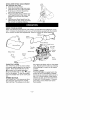
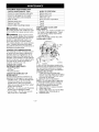
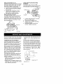
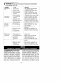
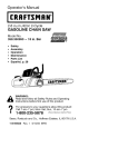
Instruction
Manual
I CRRFTSMRN°I
25cc/1.5 cu.in. 2-Cycle
185 MPH/385 CFM
GASOLINE POWERED
BLOWERNAC
Model No.
358.797300
•
Safety
• Assembly
•
•
Operation
Maintenance
•
Parts
•
Espa_ol
A
9
List
WARNING:
Read and follow all Safety Rules and Operating
Instructions before first use of this product.
For answers to your questions about this product:
Call 7 am-7 pm, Mon.-Sat., or 10 am-7 pm, Sun.
1-800-235-5878
Sears,
530088072
Roebuck
10/1/01
and Co., Hoffman
(Hours
listed are Central Time)
Estates,
IL 60179
U.S.A.
Warranty Statement
Safety Rules
Assembly
Operation
Maintenance
Service & Adjustments
2
2
4
6
9
10
Storage
Troubleshooting
Table
Emissions Statement
Parts List
Spanish
Parts and Ordering
11
12
12
14
17
Back
FULL TWO YEAR WARRANTY ON CRAFTSMAN ® GAS BLOWER
For two (2) years from date of purchase, when this Gas Blower is maintained,
lubricated, and tuned up according to the instructions in the instruction manual,
Sears will repair, free of charge, any defects in material or workmanship.
This warranty excludes blower tubes, spark plug, and air cleaner, which are expendable parts and become worn during normal use.
If this blower is used for commercial purposes, this warranty applies for 90 days from
the date of purchase. If this Blower is used for rental purposes, this warranty applies
for 30 days from the date of purchase. This warranty applies only while this product
is in use in the United States.
WARRANTY SERVICE IS AVAILABLE BY RETURNING THE BLOWER TO THE NEAREST
SEARS STORE OR SERVICE CENTER IN THE UNITED STATES.
This warranty gives you specific legal rights, and you may also have other rights
which vary from state to state.
Sears, Roebuck and Co,, D/817WA, Hoffman Estates, IL 60179
_WARNING:
Failure to follow all
Safety Rules and Precautions can result in serious injury.
KNOW YOUR UNIT
• Read your instruction manual carefully until you completely understand
and can follow all warnings and
safety rules before operating the unit.
• Restrict unit to users who understand and will follow all warnings and
safety rules in this manual
_LWARNING:
Inspect area before
starting unit. Remove all debris and
hard objects such as rocks, glass,
wire, etc. that can ricochet, be thrown,
or otherwise cause injury or damage
during operation.
Use your unit as a blower for:
• Sweeping debris or grass clippings
from driveways, sidewalks, patios, etc.
• Blowing grass clippings, straw, or
leaves into piles, around joints, or between bricks.
Use your unit as a vacuum for:
• Picking up dry material such as
leaves, grass, small twigs, and bits of
paper.
• For best results during vacuum use,
operate your unit at high speed.
• Move slowly back and forth over the
material as you vacuum. Avoid forcing the unit into a pile of debris as
this can clog the unit.
• Keep the vacuum tube about an inch
above the ground for best results.
PLAN AHEAD
• Always wear eye protection when operating, servicing, or performing maintenance on unit. Wearing eye protection will help to prevent rocks or debris
from being blown or ricocheting into
eyes and face which can result in
blindness and/or serious injury. Eye
protection should be marked Z87.
• Always wear foot protection. Do not
go barefoot or wear sandals.
• Always wear respirator or face mask
when working with unit in dusty environments.
• Secure hair above shoulder length.
Secure or remove jewelry, loose
clothing, or clothing with loosely
hanging straps, ties, tassels, etc.
They can be caught in moving parts.
• Donotoperate
unitwhen
youare
picked
upbytheairintake
and
tired,ill,upset,
orifyouareunder
the thrown
outthrough
discharge
openinfluence
ofalcohol,
drugs,
ormedi- ing,damaging
unit,property,
orcauscation.
ingserious
injury
tobystanders
or
• Keep
children,
bystanders,
andanioperator.
malsaway
fromworkareaamini• Avoid
dangerous
environments.
Do
notuseinunventilated
areas
or
mumof30feet(10meters)
when
starting
oroperating
unit.Donot
where
explosive
vapors
orcarbon
point
blower
nozzle
inthedirection
of monoxide
buildupcouldbepresent.
• Donotoverreach
orusefromunstapeople
orpets.
blesurfaces
suchasladders,
trees,
HANDLE
FUEL
WITH
CAUTION,
ITIS steep
slopes,
rooftops,
etc.Keep
firm
HIGHLY
FLAMMABLE
footing
andbalance
atalltimes.
• Eliminate
allsources
ofsparks
or
• Never
place
objects
inside
the
flame
(including
smoking,
open
blower
tubes;
always
direct
theblowflames,
orworkthatcancause
ingdebris
away
frompeople,
anisparks)
intheareas
where
fuelis
mals,
glass,
andsolidobjects
such
mixed,
poured,
orstored.
automobiles,
walls,
etc.The
• Mixandpour
fuelinanoutdoor
area; astrees,
ofaircancause
rocks,
dirt,or
store
fuelinacool,
dry,wellventilated force
tobethrown
ortoricochet
place;
useanapproved,
marked
con- sticks
which
canhurtpeople
oranimals,
tainer
forallfuelpurposes.
glass,
orcause
other
damage.
• Donotsmoke
while
handling
fuelor • break
Never
rununitwithout
theproper
while
operating
theunit.
equipment
attached.
When
using
• Make
suretheunitisproperly
asunitasablower,
always
install
sembled
andingoodoperating
con- your
blower
tubes.
When
using
theopdition.
tional
vacuum
kit,always
install
vac• Donotfillfueltankwhileengine
is
uumtubes
andvacuum
bagassemrunning.
surevacuum
bagassem• Avoid
spilling
fueloroil.Wipe
upfuel bly.Make
blyiscompletely
zipped.
spillsbefore
starting
engine.
• Check
airintake
opening,
blower
• Move
atleast10feet(3meters)
tubes,
andvacuum
tubes
frequently,
away
fromfuelandfueling
sitebealways
withengine
stopped
and
forestarting
engine.
plugdisconnected.
Keep
vents
• Always
storegasoline
inacontainer spark
anddischarge
tubes
freeofdebris
approved
forflammable
liquids.
which
canaccumulate
andrestrict
OPERATE
YOUR
UNIT
SAFELY
proper
airflow.
Never
place
anyobject
inairintake
_kWARNING:
Stoptheengine
be- • opening
asthis
could
r
estrict
proper
air
foreopening
thevacuum
inletdoor.
andcause
damage
totheunit.
Theengine
must
bestopped
andthe • flow
Never
useforspreading
chemicals,
impeller
blades
nolonger
turning
to
orothersubstances
which
avoid
serious
injury
fromtherotating fertilizers,
maycontain
toxicmaterials.
blades.
• Toavoid
spreading
fire,donotuse
• Inspect
unitbefore
eachusefor
near
leaf
o
rbrush
fires,
fireplaces,
worn,
loose,
missing,
ordamaged
barbecue
pits,ashtrays,
etc.
parts.
Donotuseuntilunitisin
• Useonlyforjobsexplained
inthis
proper
working
order.
manual.
• Keep
outside
surfaces
freefromoil
andfuel.
MAINTAIN
YOUR
UNIT
PROPERLY
• Have
allmaintenance
other
thanthe
• Never
startorrunengine
inside
a
recommended
procedures
described
closed
room,
building
orother
unventilated
area.Breathing
exhaust
intheinstruction
manual
performed
fumes
cankill.
bya Sears
Service
Center.
• Toavoid
static
electricity
shock,
do
• Disconnect
spark
plugbefore
pernotwear
rubber
gloves
oranyother forming
maintenance
except
forcarinsulated
gloves
while
operating
unit. buretor
adjustments.
• Donotsetunitonanysurface
ex• Useonlyrecommended
CraftsmanZ
ceptaclean,
hard
areawhileengine replacement
parts;
useofanyother
isrunning.
Debris
suchasgravel,
parts
mayvoidyourwarranty
and
sand,
dust,
grass,
etc.could
be
cause
damage
toyourunit.
• Empty
fueltankbefore
storing
the
teetheavoidance
ofthese
problems.
whooperate
power
toolsona
unit.Useupfuelleftincarburetor
by Users
andregular
basis
must
monistarting
engine
andletting
itrununtil continual
torclosely
theirphysical
condition
and
itstops.
ofthistool.
• Donotuseanyaccessory
orattach- thecondition
ment
other
thanthose
recommendedSPECIAL
NOTICE:
Forusers
onU.S.
bymanufacturer
forusewithyourunit. Forest
Land
andinsome
states,
includ• Donotstore
theunitorfuelina
ingCalifornia
(Public
Resources
Codes
closed
areawhere
fuelvapors
can 4442
and4443),
Idaho,
Maine,
Minnereach
sparks
oranopenflame
from sota,
NewJersey,
Oregon,
andWashhotwater
heaters,
electric
motors
or ington:
Certain
internal
combustion
enswitches,
furnaces,
etc.
gines
operated
onforest,
brush,
and/or
• Store
inadryareaoutofreach
of
grass
covered
landintheabove
areas
children.
arerequired
tobeequipped
withaspark
screen,
maintained
ineffective
SAFETY
NOTICE:
Exposure
tovibra- arresting
order,
ortheengine
must
be
tionsthrough
prolonged
useofgaso- working
constructed,
equipped,
and
maintained
linepowered
hand
toolscould
cause fortheprevention
offire.Check
with
blood
vessel
ornerve
damage
inthe
your
state
o
rlocal
authorities
forregulafingers,
hands,
andjoints
ofpeople tionspertaining
tothese
requirements.
prone
tocirculation
disorders
orabnor- Failure
tofollow
these
requirements
isa
malswelling.
Prolonged
useincold
violation
ofthelaw.
Thisunitisnotfactoweather
hasbeenlinked
toblood
ves- ryequipped
withaspark
arresting
seldamage
inotherwise
healthy
screen;
however,
aspark
arresting
people.
Ifsymptoms
occur
suchas
screen
isavailable
asanoptional
part.
If
numbness,
pain,
lossofstrength,
aspark
arresting
screen
isrequired
in
change
inskincolor
ortexture,
orloss your
area,
contact
Sears
Service
forthe
offeeling
inthefingers,
hands,
or
correct
kit.Thespark
arresting
screen,
joints,
discontinue
theuseofthistool blower
tubes,
andnozzles
must
beasandseekmedical
attention.
An
sembled
tounittobeinfullcompliance
antivibration
system
doesnotguaran- withregulations.
CARTON
CONTENTS
Check
carton
contents
against
thefollowing
list.
Model 358.797300
• Blower
• Blower tube
• Elbow tube
• Vacuum bag
• Upper vacuum tube
• Lower vacuum tube
• 2-Cycle Engine Oil
NOTE: It is normal for the fuel filter to
rattle in the empty fuel tank.
ASSEMBLY
,_WARNING:
Stop engine and be
sure the impeller blades have stopped
turning before opening the vacuum inlet door or attempting to insert or remove the vacuum tubes. The rotating
blades can cause serious injury.
,_ WARNING:
unit assembled,
If you receive your
repeat all steps to en-
sure your unit is properly assembled
and all fasteners are secure.
•
A standard screwdriver is required
for assembly.
BLOWER
ASSEMBLY
BLOWER TUBE ASSEMBLY
If you have already assembled your
unit for use as a vacuum, remove the
vacuum tubes and collection bag.
1. Align the rib on the blower tube
with the groove in the blower outlet;
slide the tube into place.
NOTE: Tube clamp must be loose
enough to allow blower tube to be inserted in blower outlet. Loosen tube
clamp by turning knob counterclockwise.
/'_'_.
Blower
_.,.€'_"_
Outlet
Blower
_'_.
_.
Groove
2.
Tube
',
Rib
Tighten the tube clamp by turning
the knob clockwise.
3. Toremove
thetube,
turntheknob
toloosen
clamp;
remove
tube.
VACUUM
ASSEMBLY
VACUUM
BAGASSEMBLY
1. Open
thezipper
onthevacuum
bagandinsert
theelbow
tube.
2. Push
thesmallendoftheelbow
tubethrough
thesmallopening
in
thebag.
Elbow
Tube
Vacuum Tube
Upper
Lower
Vacuum Tube
2.
Latch
Small
Opening
/
3.
4.
_
_!_
_"]
.....
Blower
Latch Area
Vacuum
_,
Outlet
_._-_J7 - Inlet Cover
Rib
NOTE: Make sure edge of the small
opening is flush against the flared area
of the elbow tube, and the rib on the
elbow tube is on the bottom.
_
A_
3.
Zipper
Opening
Insert a screwdriver into the latch
area on the vacuum inlet cover.
4.
Gently tilt the handle of the screwdriver toward the back of the unit
while pulling up on the vacuum inlet cover with your other hand.
Hold the vacuum inlet cover open
until upper vacuum tube is installed.
Vacuum Inlet
Close the zipper on the bag. Make
sure the zipper is closed completely.
Remove blower tube from engine.
Retaining
Pest
Vln°, tm
Cover
5.
Place the hooks on the vacuum tube
on the retaining posts; pivot tube into
position. Secure vacuum tube by
turning the knob clockwise until tight.
_ Gro ve
5.
Insert the elbow tube into the blower
outlet. Make sure elbow tube is
aligned with the blower outlet
groove.
6. Turn clamp knob clockwise to tighten.
VACUUM TUBE ASSEMBLY
1. Align the lower vacuum tube as
shown. Push lower vacuum tube
into upper vacuum tube.
--
6,
_-- _oks
When converting back to the blower feature, make sure latch on the
vacuum inlet cover is securely fastened.
SHOULDER
STRAP
ADJUSTMENT
(for vacuum use only)
1. Hold the unit as shown.
2. Pass the shoulder strap over your
head and onto your right shoulder.
3. Extend your left arm toward the
rear of the vacuum bag.
4. Adjust shoulder strap until the vacuum bag/shoulder
strap seam lies
between your thumb and index
finger.
5. Make sure air flows freely from the
elbow tube into bag. If bag is kinked,
the unit will not operate properly.
KNOW YOUR BLOWER
READ THIS INSTRUCTION MANUAL AND SAFETY RULES BEFORE OPERATING YOUR
UNIT. Compare the illustrations with your unit to familiarize yourself with the location
of the various controls and adjustments. Save this manual for future reference.
Vacuum T
Lower
Vacuum Tube
Upper
_
Primer Button
THROTTLE
LEVER
The THRO-i-rLE LEVER is used to select
the desired engine speed and to stop the
engine. Move the throttle lever to the
position for full speed operation.
Move the throttle lever to the _
position for idle speed. To stop the engine,
move the throttle lever to the STOP position.
the engine with fewer pulls on the starter
rope. Activate primer button by pressing
it and allowing it to return to its original
position.
CHOKE LEVER
The CHOKE helps to supply fuel to the
engine to aid in cold starting. Activate
the choke by moving the choke lever to
the FULL CHOKE position. After engine
attempts to start, move the choke lever
to the HALF CHOKE position. Once engine starts, move choke lever to the
RUN position.
PRIMER BUTTON
The PRIMER BU-i-ION removes air _om
the carburetor and fuel lines and fills
them with fuel. This allows you to start
-6-
OPERATING TIPS
• While vacuuming or blowing debris,
hold the unit with the muffler side facing away from your body and clothes
(see OPERATING POSITION).
• To reduce the risk of hearing loss
associated with sound level(s), hearing protection is required.
• To reduce the risk of injury associated
with contacting rotating parts, stop the
engine before installing or removing
attachments. Do not operate without
guard(s) in place.
• Operate power equipment only at reasonable hours-not early in the morning or late at night when people might
be disturbed. Comply with times listed
in local ordinances. Usual recommendations are 9:00 a.m. to 5:00 p.m.,
Monday though Saturday.
• To reduce noise levels, limit the number of pieces of equipment used at
any one time.
• To reduce noise levels, operate power blowers at the lowest possible
throttle speed to do the job.
• Use rakes and brooms to loosen
debris before blowing.
• In dusty conditions, slightly dampen
surfaces or use a mister attachment
when water is available.
• Conserve water by using power blowers instead of hoses for many lawn
and garden applications, including
areas such as gutters, screens, patios,
grills, porches, and gardens.
• Watch out for children, pets, open
windows, or freshly washed cars.
Blow debris away safely.
• Use the full blower nozzle extension
so the air stream can work close to
the ground.
• After using blowers and other equipment, CLEAN UP! Dispose of debris
in trash receptacles.
OPERATING POSITION
Protection
I
Blower
Vacuum
BEFORE
STARTING
'_LWARNING:
ENGINE
Be sure to read the
fuel information in the safety rules
before you begin. If you do not
understand the safety rules, do not
attempt to fuel your unit. Call
1-800-235-5878.
FUELING
ENGINE
,_LWARNING:
Remove fuel cap
slowly when refueling.
This engine is certified to operate on
unleaded gasoline. Before operation,
gasoline must be mixed with a good
quality 2-cycle air-cooled engine oil.
We recommend Craftsman brand oil.
Mix gasoline and oil at a ratio of 40:1
(A 40:1 ratio is obtained by mixing 3.2
ounces of oil with 1 gallon of unleaded
gasoline). DO NOT USE automotive oil
or boat oil. These oils will cause engine damage. When mixing fuel, follow
instructions printed on container.
Once oil is added to gasoline, shake
container momentarily to assure that
the fuel is thoroughly mixed. Always
read and follow the safety rules relating to fuel before fueling your unit.
IMPORTANT
Experience indicates that alcohol
blended fuels (called gasohol or using
ethanol or methanol) can attract moisture which leads to separation and
formation of acids during storage.
Acidic gas can damage the fuel system of an engine while in storage.
To avoid engine problems, empty the
fuel system before storage for 30 days
or longer. Drain the gas tank, start the
engine and let it run until the fuel lines
and carburetor are empty. Use fresh
fuel next season.
Never use engine or carburetor cleaner products in the fuel tank or permanent damage may occur.
Fuel stabilizer is an acceptable alternative in minimizing the formation of
fuel gum deposits during storage.
Craftsman brand oil is already blended
with fuel stabilizer. See the STORAGE
section for additional information.
STOPPING YOUR ENGINE
• To stop the engine, move the throttle
lever to the STOP position.
STARTING
THEENGINE
_LWARNING:
You MUST make sure
the tubes are secure before using the
unit.
• Fuel engine. Move at least 10 feet (3
meters) away from the fueling site.
• Hold the unit in the starting position
as shown. Make sure the blower end
is directed away from people, animals, glass, and solid objects.
.,_i@__p
STARTING POSITION
Blower
Vacuum
,_ WARNING:
When starting engine,
hold the unit as illustrated. Do not set
unit on any surface except a clean, hard
area when starting engine or while engine is running. Debris such as gravel,
sand, dust, grass, etc. could be picked
up by the air intake and thrown out
through the discharge opening, damaging the unit or property, or causing serious injury to bystanders or the operator.
STARTING A COLD ENGINE (or a
warm engine after running out of
fuel)
1. Move the throttle lever to the
position.
2. Move the choke lever to the FULL
CHOKE position.
3. Slowly press the primer button 8
times.
Throttle Lever
Primer Button
\4
Choke Lever
4,
Pull starter handle sharply until the
engine attempts to run, but no
more than 5 pulls (below 30°F, 8
pulls).
-8-
NOTE: If the engine attempts to start
before the 5th pull, go to the next step
immediately.
5. Move choke lever to HALF CHOKE.
6. Pull the starter handle sharply until
the engine runs, but no more than
5 pulls (below 30°F, 10 pulls).
7. After a 5 second warm-up, move
the choke lever to the RUN position.
8. Allow the unit to run for 30 more
seconds at RUN before moving the
throttle lever to the _
position.
If the engine has not started after 5
pulls (at HALF CHOKE), repeat the
STARTING A COLD ENGINE procedure.
If the engine still does not start, proceed to STARTING A FLOODED ENGINE.
9. To stop the engine, move the
throttle lever to the STOP position.
STARTING A WARM ENGINE
1. Move the throttle lever to the 4r_
position.
2. Pull the starter handle sharply until
the engine starts, but no more than
5 pulls.
NOTE: If the engine has not started,
pull starter handle sharply for 5 more
pulls. If engine still does not run, it is
probably flooded. Proceed to STARTING A FLOODED ENGINE.
3.
To stop the engine, move the
throttle lever to the STOP position.
STARTING A FLOODED ENGINE
Flooded engines can be started by placing the choke lever in the RUN position.
Move throttle lever to the fast position
4r_ ; then, pull rope until engine starts.
After engine starts, move the throttle lever to the slow position -aF to allow engine to idle.
Starting could require pulling the starter
rope many times depending on how
badly the unit is flooded. If the unit still
doesn't start, refer to the
TROUBLESHOOTING TABLE or call
1-800-235-5878.
CUSTOMER
RESPONSIBILITIES
CARE & MAINTENANCE
TASK
WHEN TO PERFORM
Check for loose fasteners
and parts
Before each use
Check for damaged
Before each use
or worn parts
Inspect and clean unit and labels
Clean air filter
After each use
Replace spark plug
Replace fuel filter
Yearly
Yearly
Check muffler mounting
Every 5 hours of operation
screws
Yearly
WARNING:
Avoid touching muffler unless engine and muffler are cold.
A hot muffler can cause serious burns.
,_,WARNING:
Stop engine and be
sure the impeller blades have stopped
turning before opening the vacuum inlet door or attempting to insert or remove the vacuum or blower tubes.
The rotating blades can cause serious
injury. Always disconnect the spark
plug before performing maintenance or
accessing movable parts.
GENERAL RECOMMENDATIONS
The warranty on this unit does not cover items that have been subjected to
operator abuse or negligence. To receive full value from the warranty, the
operator must maintain unit as instructed in this manual. Various adjustments
will need to be made periodically to
properly maintain your unit.
CHECK FOR LOOSE
FASTENERS AND PARTS
• Spark Plug Boot
• Air Filter
• Housing Screws
CHECK FOR DAMAGED
OR
WORN PARTS
Contact Sears Service Center for replacement of damaged or worn parts.
• Throttle Lever - Ensure throttle lever
functions properly by moving the
throttle lever to the STOP position.
Make sure engine stops; then restart
engine and continue.
• Fuel Tank - Do not use unit if fuel tank
shows signs of damage or leaks.
• Vacuum Bag - Do not use vacuum
bag if it is torn or damaged.
-9-
INSPECT AND CLEAN UNIT
AND LABELS
• After each use, inspect complete unit
for loose or damaged parts. Clean
the unit using a damp cloth with a
mild detergent.
• Wipe off unit with a clean dry cloth.
CLEAN AIR FILTER
__
Air Filter
cover
\
.JJ_F "_
J
Screws
/
Air Filter
A dirty air filter decreases engine performance and increases fuel consumption and harmful emissions. Always
clean after every 5 hours of operation.
Cleaning the air filter:
1. Clean the cover and the area
around it to keep debris from falling
into the carburetor chamber when
the cover is removed.
2. Remove parts as illustrated.
NOTE: Do not clean filter in gasoline
or other flammable solvent. Doing so
can create a fire hazard or produce
harmful evaporative emissions.
3. Wash the filter in soap and water.
4. Allow filter to dry.
5. Apply a few drops of oil to the filter;
squeeze filter to distribute oil.
6. Replace parts.
REPLACE SPARK PLUG
Replace spark plug each year to ensure
the engine starts easier and runs better.
Set spark plug gap at 0.025 inch. Ignition timing is fixed, nonadjustable.
1. Twist, then pull off spark plug boot.
2. Remove spark plug from cylinder
and discard.
3. Replace with Champion CJ-6Y
spark plug and tighten securely
with a 3/4 in. socket wrench.
4. Reinstall the spark plug boot.
REPLACE FUEL FILTER
To replace fuel filter, drain unit by running it dry of fuel, then remove fuel
cap/retainer assembly from tank. Pull
filter from tank and remove it from the
fuel line. Install new fuel filter on fuel
line; reinstall parts.
CHECK MUFFLER MOUNTING
SCREWS
Once each year, ensure muffler
mounting screws are secure and tightened properly to prevent damage.
Mounting
_,
Screw
Muffler Cover
_'_/_u*_\
H°les
J'_
Screws
1.
2.
3.
4.
Line
'
I
___
Loosen and remove the 2 screws
from the muffler cover.
Remove the muffler cover.
Tighten the 2 muffler mounting
screws securely.
Reinstall muffler cover and 2
screws. Tighten securely.
Fuel Filter
We recommend all service and adjustments not listed in this manual be performed by your Sears Service Center.
CARBURETOR
ADJUSTMENT
Carburetor adjustment is critical and if
done improperly can permanently
damage the engine as well as the carburetor. If you require further assistance or are unsure about performing
this procedure, call our customer assistance help line at 1-800-235-5878.
Old fuel, a dirty air filter, a dirty fuel filter, or flooding may give the impression of an improperly adjusted carburetor. Check these conditions before
adjusting the carburetor.
The carburetor has been carefully set
at the factory. Adjustments may be
necessary if you notice any of the following conditions:
• Engine will not idle. See LOW SPEED
MIXTURE ADJUSTMENT (L) under adjusting procedure.
• Engine dies or hesitates instead of accelerating. See ACCELERATION CHECK
under adjusting procedure.
-10-
• Loss of power. See MIXTURE ADJUSTMENT (L or H) under adjusting procedure.
There are two adjustment screws on
the carburetor. The low speed adjustment screw is marked with the letter L,
and the high speed adjustment screw
is marked with the letter H. The throttle
lever is used to control engine speed.
The throttle lever can be placed in one
offour positions: STOP, IDLE or -4111_
FULL THROTTLE or _, and one intermittent position.
im er Button
ever
nt "H"
Adjustment
"L"
ADJUSTING
PROCEDURE
CAUTION:
Do not force plastic ]imiter
caps on screws beyond the built-in
stops or damage will occur.
Initial Settings
1. Turn both mixture screws (L and H)
counterclockwise until they stop.
2. Start engine, let it run for 3 minutes,
then proceed to adjust screws according to the instructions below. If
engine performance at initial settings
is acceptable, no further adjustments
are necessary. If engine does not
start, refer to TROUBLESHOOTING
TABLE. If still unable to remedy situation, call 1-800-235-5878.
Low Speed Mixture Adjustment
- L
1. Allow the engine to idle.
2. Turn low speed mixture screw (L)
slowly clockwise until the speed begins to drop.
3. Turn the low speed mixture screw
(L) counterclockwise until the speed
,_ WARNING:
Perform the following
steps after each use:
• Allow engine to cool, and secure the
unit before storing or transporting.
• Store unit and fuel in a well ventilated area where fuel vapors cannot
reach sparks or open flames from
water heaters, electric motors or
switches, furnaces, etc.
• Store unit with all guards in place.
Position unit so that any sharp object
cannot accidentally cause injury.
• Store unit and fuel well out of the
reach of children.
SEASONALSTORAGE
Prepare unit for storage at end of season or if it will not be used for 30 days
or more.
If your unit is to be stored for a period
of time:
• Clean the entire unit before lengthy
storage.
• Store in a clean dry area.
• Lightly oil external metal surfaces.
FUEL SYSTEM
Under FUELING ENGINE in the OPERATION section of this manual, see message labeled IMPORTANT regarding
the use of gasohol in your engine.
Fuel stabilizer is an acceptable alternative in minimizing the formation of fuel
-11
increases and then starts to drop
again.
4. Set the low speed mixture screw (L)
at the midpoint between the two
positions.
High Speed Mixture Adjustment
- H
CAUTION:
Adjust the mixture screw
1/16 of a turn at a time. A 1/16 turn is
about the width of the slot in the top of
the screw.
1. Run engine at full throttle.
2. Turn the high speed mixture screw
(H) counterclockwise until it stops.
3. Turn the high speed mixture screw
(H) 1/16 of a turn clockwise at a time
until the engine runs smoothly.After
completing adjustments, check for
acceleration. Reset if necessary.
Acceleration Check
If engine dies or hesitates instead of
accelerating, turn the low speed mixture screw (L) counterclockwise
until
you have smooth acceleration.
gum deposits during storage. Add stabilizer to gasoline in fuel tank or fuel storage container. Follow the mix instructions found on stabilizer container. Run
engine at least 5 minutes after adding
stabilizer.
Craftsman 40:1,2-cycle
engine
cooled) is already blended with
stabilizer. If you do not use this
oil, you can add a fuel stabilizer
fuel tank.
oil (air
fuel
Sears
to your
ENGINE
• Remove spark plug and pour 1 teaspoon of 40:1,2-cycle
engine oil (air
cooled) through the spark plug opening. Slowly pull the starter rope 8 to
10 times to distribute oil.
• Replace spark plug with new one of
recommended type and heat range.
• Clean air filter.
• Check entire unit for loose screws,
nuts, and bolts. Replace any damaged, broken, or worn parts.
• At the beginning of the next season,
use only fresh fuel having the proper
gasoline to oil ratio.
OTHER
• Do not store gasoline from one season to another.
• Replace your gasoline can if it starts
to rust.
-
,_OUBLESHOOTING
TABLE
WARNING:
Always stop unit and disconnect spark plug before performing any of the recommended remedies below other than remedies that require operation of the unit.
TROUBLE
Engine will not
start.
CAUSE
REMEDY
1. See "Starting a Flooded Engine"
in Operation section.
2. Fill tank with correct fuel mixture.
1. Engine flooded.
2. Fuel tank empty.
3. Spark plug not firing.
4. Fuel not reaching
carburetor.
5. Compression
Engine will not
idle properly.
low.
1. Fuel not reaching
carburetor.
2. Carburetor requires
adjustment.
3. Crankshaft seals worn.
4. Compression
Engine will not
accelerate,
lacks power, or
dies under a
load.
low.
1. Air filter dirty.
2. Fuel not reaching
carburetor.
1. Check for dirty fuel filter; replace.
Check for kinked or split fuel line;
repair or replace.
2. See "Carburetor Adjustment" in
Service and Adjustments
section.
3. Contact your Sears Service Center.
4. Contact your Sears Service Center.
1. Clean or replace air filter.
2. Check for dirty fuel filter; replace.
Check for kinked or split fuel line;
repair or replace.
3. Clean or replace spark plug
and re-gap.
4. See "Carburetor
Adjustment" in
Service and Adjustments section.
5. Contact your Sears Service Center.
6. Contact your Sears Service Center.
3. Spark plug fouled.
4. Carburetor requires
adjustment.
5. Carbon build up.
6. Compression
low.
Engine smokes
excessively.
1. Choke partially on.
2. Fuel mixture incorrect.
Engine
3. Air filter dirty.
4. Carburetor requires
adjustment.
1. Fuel mixture incorrect.
runs hot.
3. Install new spark plug.
4. Check for dirty fuel filter; replace.
Check for kinked or split fuel line;
repair or replace.
5. Contact your Sears Service Center.
2. Spark plug incorrect.
3. Carburetor requires
adjustment.
4. Carbon build up.
1. Adjust choke.
2. Empty fuel tank and refill with
correct fuel mixture.
3. Clean or replace air filter.
4. See "Carburetor Adjustment" in
Service and Adjustments section.
1. See "Fueling
section.
Engine"
in Operation
2. Replace with correct spark plug.
3. See "Carburetor
Adjustment" in
Service and Adjustments section.
4. Contact your Sears Service Center.
YOUR WARRANTY RIGHTS AND
OBLIGATIONS:
The U. S. Environmental Protection Agency and Sears,
Roebuck and Co., U.S.A., are pleased
to explain the emissions control system warranty on your lawn and garden
equipment engine. All new utility and
lawn and garden equipment engines
must be designed, built, and equipped
to meet the stringent anti-smog standards. Sears must warrant the emission control system on your lawn and
garden equipment engine for the periods of time listed below provided there
has been no abuse, neglect, or improper maintenance of your lawn and
garden equipment engine. Your emission control system includes parts
such as the carburetor and the ignition
system. Where a warrantable condition
exits, Sears will repair your lawn and
garden equipment engine at no cost to
you. Expenses covered under warranty include diagnosis, parts and labor.
-12-
MANUFACTURER'S
WARRANTY
COVERAGE: If any emissions related
part on your engine (as listed under
Emissions Control Warranty Parts List)
is defective or a defect in the materials
or workmanship
of the engine causes
the failure of such an emission related
part, the part will be repaired or replaced by Sears. OWNER'S WARRANTY RESPONSIBILITIES:
As the
lawn and garden equipment engine
owner, you are responsible for the performance of the required maintenance
listed in your instruction manual. Sears
recommends that you retain all receipts covering maintenance on your
lawn and garden equipment engine,
but Sears cannot deny warranty solely
for the lack of receipts or for your failure to ensure the performance of all
scheduled maintenance.
As the lawn
and garden equipment engine owner,
you should be aware that Sears may
deny you warranty coverage if your
lawn and garden equipment engine or
a part of it has failed due to abuse, neglect, improper maintenance,
unapproved modifications, or the use of
parts not made or approved by the
original equipment manufacturer.
You
are responsible for presenting your
lawn and garden equipment engine to
a Sears authorized repair center as
soon as a problem exists. Warranty
repairs should be completed in a reasonable amount of time, not to exceed
30 days. If you have any questions
regarding your warranty rights and responsibilities, you should contact your
nearest authorized service center or
call Sears at 1-800-469-4663
WARRANTY COMMENCEMENT
DATE:
The warranty period begins on the
date the lawn and garden equipment
engine is purchased.
LENGTH OF
COVERAGE: This warranty shall be
for a period of two years from the initial
date of purchase. WHAT IS COVERED: REPAIR OR REPLACEMENT
OF PARTS. Repair or replacement of
any warranted part will be performed at
no charge to the owner at an approved
Sears servicing center. If you have any
questions regarding your warranty
rights and responsibilities,
you should
contact your nearest authorized ser-
-13-
vice center or call Sears at
1-800-469-4663.
WARRANTY
PERIOD: Any warranted part which is not
scheduled for replacement as required
maintenance, or which is scheduled
only for regular inspection to the effect
of "repair or replace as necessary"
shall be warranted for 2 years. Any
warranted part which is scheduled for
replacement as required maintenance
shall be warranted for the period of
time up to the first scheduled replacement point for that part. DIAGNOSIS:
The owner shall not be charged for
diagnostic labor which leads to the determination that a warranted part is defective if the diagnostic work is performed at an approved Sears servicing
center. CONSEQUENTIAL
DAMAGES: Sears may be liable for damages to other engine components
caused by the failure of a warranted
part still under warranty. WHAT IS
NOT COVERED: All failures caused
by abuse, neglect, or improper maintenance are not covered. ADD-ON OR
MODIFIED PARTS: The use of add-on
or modified parts can be grounds for disallowing a warranty claim. Sears is not
liable to cover failures of warranted
parts caused by the use of add-on or
modified parts. HOW TO FILE A
CLAIM: If you have any questions regarding your warranty rights and responsibilities, you should contact your
nearest authorized service center or
call Sears at 1-800-469-4663.
WHERE
TO GET WARRANTY SERVICE: Warranty services or repairs shall be provided at all Sears service centers, call:
1-800-469-4663.
MAINTENANCE, REPLACEMENT AND REPAIR OF EMISSION RELATED PARTS: Any Sears
approved replacement part used in the
performance of any warranty maintenance or repair on emission related
parts will be provided without charge to
the owner if the part is under warranty.
EMISSION CONTROL WARRANTY
PARTS LIST: Carburetor, Ignition System: Spark Plug (covered up to maintenance schedule), Ignition Module.
MAINTENANCE
STATEMENT: The
owner is responsible for the performance of all required maintenance as
defined in the instruction manual.