1
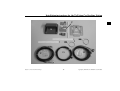
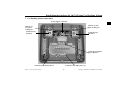
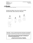
Installation instructions for the TriVision Car Docking Station
Contents
1.
2.
3.
4.
5.
6.
7.
8.
9.
10.
11.
12.
13.
Symbols used in this installation guide . . . . . . . . . . . . . . . . . . . . . . . . . . . . . . . . . . . . . . . . . 30
Prior to installation . . . . . . . . . . . . . . . . . . . . . . . . . . . . . . . . . . . . . . . . . . . . . . . . . . . . . . . . . 31
Safety instructions . . . . . . . . . . . . . . . . . . . . . . . . . . . . . . . . . . . . . . . . . . . . . . . . . . . . . . . . . 31
Installation instructions. . . . . . . . . . . . . . . . . . . . . . . . . . . . . . . . . . . . . . . . . . . . . . . . . . . . . . 33
Components in the installation kit . . . . . . . . . . . . . . . . . . . . . . . . . . . . . . . . . . . . . . . . . . . . . 34
Connection diagram for TriVision with Car Docking Station . . . . . . . . . . . . . . . . . . . . . . . . 36
Car Docking Station connections . . . . . . . . . . . . . . . . . . . . . . . . . . . . . . . . . . . . . . . . . . . . . . 37
General information on installation of the Car Docking Station . . . . . . . . . . . . . . . . . . . . . . 38
Installation instructions for the mounting plate . . . . . . . . . . . . . . . . . . . . . . . . . . . . . . . . . . . 41
Routing wiring / Installing antennas. . . . . . . . . . . . . . . . . . . . . . . . . . . . . . . . . . . . . . . . . . . . 49
Connecting the power supply . . . . . . . . . . . . . . . . . . . . . . . . . . . . . . . . . . . . . . . . . . . . . . . . . 53
Final installation of the Car Docking Station . . . . . . . . . . . . . . . . . . . . . . . . . . . . . . . . . . . . . 54
NOTICE . . . . . . . . . . . . . . . . . . . . . . . . . . . . . . . . . . . . . . . . . . . . . . . . . . . . . . . . . . . . . . . . . 56
1. Symbols used in this installation guide
G
Warning
denotes instructions which are important for your safety and the safety of others.
denotes instructions which are important for the installation and function of the unit.
Subject to errors and technical changes
30
Copyright by Harman/Becker GmbH, D-76303 Karlsbad
Installation instructions for the TriVision Car Docking Station
2. Prior to installation
G
Warning
In order to prevent head injuries and driver distraction during driving, the driver/front passenger backrests must be
adjusted such that contact between the occupants’ heads and the TriVision, as well as viewing of the TriVision are
prevented. This must be ensured during installation of the Car Docking Station. The instructions contained in this
installation guide must be observed.
Before starting installation, please read this installation guide carefully. In particular, please pay attention to the safety and
installation instructions.
Before commencing installation, the vehicle must be checked by a specialist company to determine whether there are any
reasons preventing installation of the Car Docking Station for the TriVision, such as a roof antenna etc. It must be ensured
that sufficient clearance is maintained for opening an installed tilting/sliding sunroof.
3. Safety instructions
G
Warning
Incorrect installation
Incorrect installation may result in damage to the unit or to the vehicle. Specialist knowledge and skills are required
for installation of the Car Docking Station and its components. We strongly recommend that you have the unit
installed by a specialist workshop.
Before the commencement of installation, it must be ensured that there are no technical or design reasons preventing
installation of the Car Docking Station in the relevant vehicle.
Subject to errors and technical changes
31
Copyright by Harman/Becker GmbH, D-76303 Karlsbad
Installation instructions for the TriVision Car Docking Station
G
G
G
Warning
Risk of injury
Installing the components incorrectly may lead to injuries in the event of a road traffic accident or render safety
devices ineffective. Please refer to the instructions provided by the vehicle manufacturer.
Warning
Damage to the airbag
Installing the components in the wrong location may damage the airbag or impair its operation. Do not install the
components within the operating range of the airbag.
Warning
Risk of injury due to inadequate attachment
Attach the components so that they cannot come loose in the event of a collision or sudden braking.
Poorly attached components can be thrown forward in the vehicle in the event of sudden manoeuvres or accidents,
causing injuries to the vehicle occupants or other road users. This increased risk of injury is further aggravated if
the objects thrown forward are hit by a deploying airbag. In such cases, the objects can act as “projectiles” which
may cause fatal injuries.
Subject to errors and technical changes
32
Copyright by Harman/Becker GmbH, D-76303 Karlsbad
Installation instructions for the TriVision Car Docking Station
4. Installation instructions
Damage due to polarity reversal or short-circuit
Incorrect cable connections and short-circuits can seriously damage the unit.
Disconnect the vehicle battery for the duration of unit installation.
In order to avoid short-circuits and malfunctions, install the cables so that they cannot be pinched, kinked, chafed
or detached. Especially take this into account during installation of a unit if the vehicle is equipped with a tilting
sunroof or roof window.
Before installation, park the vehicle in a safe and level place and remove the ignition key.
Apply the parking brake.
In order to avoid malfunctions, it is absolutely essential to observe the relevant cable cross-section when using
branch connections/cable connectors.
In order to avoid short-circuits and any associated risk of fire, cables which have to be cut must be properly
insulated.
Subject to errors and technical changes
33
Copyright by Harman/Becker GmbH, D-76303 Karlsbad
Installation instructions for the TriVision Car Docking Station
5. Components in the installation kit
A. Car Docking Station
B. Mounting plate
C. Installation parts for attaching purposes - adhesive tape / Velcro strip / screws / nuts / washers / plastic clips /
plastic threaded rod
D. Plates for attachment to the vehicle roof (third attachment point)
E. Adapter box (audio/video in – e.g. for Playstation/DVD player)
F. Audio/video in connection cable from the Docking Station to the adapter box
G. Power supply connection cable to the Docking Station
H. Docking Station to audio/video out connection cable e.g. for an external screen (optional)
I. Self-adhesive window antennas (x 2)
Subject to errors and technical changes
34
Copyright by Harman/Becker GmbH, D-76303 Karlsbad
Installation instructions for the TriVision Car Docking Station
D
C
B
A
E
I
F
Subject to errors and technical changes
G
35
H
Copyright by Harman/Becker GmbH, D-76303 Karlsbad
Installation instructions for the TriVision Car Docking Station
6. Connection diagram for TriVision with Car Docking Station
DVD player
Becker
(optional)
Connection cable
Video/audio out
(optional)
Power supply
Antenna 1
Car
Docking Station
Connection
cable
Video/audio in
Adapter box
Video/audio in
(Playstation)
Antenna 2
All components are connected to the Car Docking Station.
When selecting the installation locations of the individual components, take into account the length of the cables
provided in the installation kit.
The length of the cables provided in the installation kit:
Docking Station – connection cable for audio/video in (F) to adapter box (E) approx. 5 metres
Docking Station – power supply (G) approx. 5 metres
Docking Station - antennas 1 and 2 (I) approx. 3 metres each
A cable for Docking Station - audio/video out (H) approx. 5 metres is optionally available (part number 1712144)
Subject to errors and technical changes
36
Copyright by Harman/Becker GmbH, D-76303 Karlsbad
Installation instructions for the TriVision Car Docking Station
7. Car Docking Station connections
Power supply connection
Fixture for
base plate
locking tab
Fixture for base
plate locking tab
Connection for
antenna 1
Connection for
antenna 2
Connection for DVD
player (Becker)
Connection for audio/video out
Connection for audio/video in
Subject to errors and technical changes
37
Copyright by Harman/Becker GmbH, D-76303 Karlsbad
Installation instructions for the TriVision Car Docking Station
8. General information on installation of the Car Docking Station
Ideal installation position
•
G
The Car Docking Station should be secured in the centre of the vehicle behind the front seats to provide the vehicle
occupants in the rear with the best possible view of the TriVision.
Warning
In order to prevent head injuries and driver distraction during driving, the Car Docking Station must be installed
such that contact between the driver's head and the TriVision, as well as viewing of the TriVision are prevented even
when the driver seat is in the rearmost position.
When deciding on the best installation position, ensure that the TriVision is not a nuisance to the driver or does not
obstruct his view either when open or closed.
Check all applicable national regulations and laws.
Subject to errors and technical changes
38
Copyright by Harman/Becker GmbH, D-76303 Karlsbad
Installation instructions for the TriVision Car Docking Station
Requirements for attachment in the vehicle
Dead weight / vibrations / shocks / impacts
•
The weight of the Car Docking Station, the mounting plate and the TriVision amount to approx. 1.5 kg.
To prevent severe vibrations affecting the screen under normal driving conditions and at the same time to ensure an
unimpaired view, the Car Docking Station must be secured to a frame part of the vehicle.
•
Most vehicles have struts in the roof structure that usually run across the width of the vehicle. The roof structure is
attached to these struts, which extend across the entire vehicle. These struts offer the most stable attachment for the
Car Docking Station (A).
•
The mounting plate (B) provided permits the Car Docking Station to be attached to the struts in the roof structure.
Attachment points (at least 3 stable attachment points)
•
The mounting plate (B) must be secured to at least two points of the vehicle’s strut structure. This prevents longitudinal movements or lateral rotation of the TriVision during operation or when folding out.
•
The third attachment secures the mounting plate (B) during folding out of the TriVision. This attachment can be made
directly to the roof panel by installing the plates (D), the plastic threaded rod and the double-sided adhesive tape included in the installation kit.
The third attachment point must always be used in order to counteract the vibrations and the arising lever forces.
Subject to errors and technical changes
39
Copyright by Harman/Becker GmbH, D-76303 Karlsbad
Installation instructions for the TriVision Car Docking Station
Checking the installation options in your vehicle
•
Consult a specialist company to check the installation options in your vehicle.
•
In vehicles equipped with a sunroof, the mounting plate of the Car Docking Station can usually be fastened directly
onto the struts to which the frame of the sunroof is also attached.
It must be ensured that the attaching parts do not impair the movement of the sunroof or the sunroof panel.
It must be checked whether a roof antenna prevents the installation of the Car Docking Station.
Subject to errors and technical changes
40
Copyright by Harman/Becker GmbH, D-76303 Karlsbad
Installation instructions for the TriVision Car Docking Station
9. Installation instructions for the mounting plate
G
9.1
•
G
9.2
•
Warning
Incorrect installation
Incorrect installation may result in damage to the unit or to the vehicle. Specialist knowledge and skills are required
to install the unit and its components. We strongly recommend that you have the unit installed by a specialist
workshop. Here, checks can be made to establish whether there are any reasons to prevent installation (roof antenna,
sliding roof, possible installation position etc.).
Determining the ideal installation location
First determine the ideal installation position of the Car Docking Station. Refer to the information given under “General information on installation of the Car Docking Station” on page 38 for this purpose.
Warning
In order to prevent head injuries and driver distraction during driving, the Car Docking Station must be installed
such that the possibility of contact between the driver's head and the TriVision, as well as viewing of the TriVision
are prevented even when the driver seat is in the rearmost position.
Locating support struts of the roof structure
Consult a specialist dealer to find out where the roof struts are located in your vehicle. Also find out whether any
wiring is routed between the roof and the headliner, as this could be damaged during installation of the Car Docking
Station.
Subject to errors and technical changes
41
Copyright by Harman/Becker GmbH, D-76303 Karlsbad
Installation instructions for the TriVision Car Docking Station
9.3
Attachment options on the mounting plate
3. Attachment point with the plates (D) and the threaded rod
when using the main attachment
Optional
main attachment
to the roof strut
Optional
main attachment
to the roof strut
Locking tab
Locking tab
Main attachment
to the roof strut
Main attachment
to the roof strut
3. Attachment point with the plates (D) and the threaded rod
when using the optional main attachment
Subject to errors and technical changes
42
Copyright by Harman/Becker GmbH, D-76303 Karlsbad
Installation instructions for the TriVision Car Docking Station
9.4
•
9.5
Determining the central axis of the vehicle
Determine the central axis by measuring the width of the vehicle. Mark the central axis. This permits you to attach
the mounting plate (B) centrally.
Marking out the cutout for the mounting plate
•
Hold the mounting plate (B) in the correct position on the headliner. Ensure that it will subsequently be possible to screw the main
attachment to the roof strut. Also ensure that you hold the mounting plate (B) according to the markings on the plate (front/rear).
•
Mark out the size of the cutout with a pen. The size of the cutout
is indicated by means of the slot running approx 1 cm from the
edge of the mounting plate (B). I.e., the subsequent cutout in the
headliner is a little smaller than the mounting plate.
Subject to errors and technical changes
43
Copyright by Harman/Becker GmbH, D-76303 Karlsbad
Installation instructions for the TriVision Car Docking Station
9.6
•
Cutting out the cutout for the mounting plate
Cut along the markings you made previously using a sharp knife.
If the thickness of the headliner material exceeds 8 millimetres,
it must be reduced to approx. 8 millimetres. Remove the required
amount of material on the upper side of the headliner. It must be
ensured that the part of the headliner overlapping the mounting
plate does not have a thickness exceeding 8 millimetres.
9.7
•
Measuring the distance between the headliner and the roof strut
Measure the distance between the roof strut and the upper side of the headliner.
You will require this information to determine the height of the spacers which it may be necessary to install between
the mounting plate and the roof strut.
Subject to errors and technical changes
44
Copyright by Harman/Becker GmbH, D-76303 Karlsbad
Installation instructions for the TriVision Car Docking Station
9.8
Marking the drill holes for the main attachment
•
Position the mounting plate (B) correctly between the headliner
and the roof strut.
•
The two elevated recesses are used (elevated part against the roof
strut) for subsequently screwing on the mounting plate (B).
•
Mark the position of the drill holes on the support strut.
9.9
•
Determining the distance between the mounting plate and the strut/roof
In order to maintain the distance from the support strut on the vehicle and the vehicle headliner, determine whether
spacers are required, as described under 9.7 on page 44. For this purpose, subtract the mounting plate thickness of
4 mm from the distance measured under 9.7 on page 44. The result of the subtraction gives the necessary height of
the spacers.
Subject to errors and technical changes
45
Copyright by Harman/Becker GmbH, D-76303 Karlsbad
Installation instructions for the TriVision Car Docking Station
9.10 Determining the third attachment point
•
In vehicles without a sunroof, it is usually possible to attach the mounting plate (B) to a third point on the roof panel.
•
The third attachment point of the mounting plate (B) can be attached to the roof by using the double-sided adhesive
tape, the threaded rod and the plates (D) included in the installation kit.
•
When using the main attachment (long slots) the furthest possible option from the screw connection should be selected
for the third attachment point during fastening.
When using the optional main attachment, the third attachment point must be located on the opposite side.
Please refer to the description of the mounting plate under “Attachment options on the mounting plate” on page 42.
Once attached, the provided double-sided adhesive tape can no longer be removed.
Subject to errors and technical changes
46
Copyright by Harman/Becker GmbH, D-76303 Karlsbad
Installation instructions for the TriVision Car Docking Station
9.11 the mounting plate to the support struts
•
Drill holes with the correct diameter (for the sheet-metal screws being used) in the holes marked on the roof strut, see 9.8 on page 45.
•
Fasten the mounting plate (B) with at least two sheet-metal
screws. Use the correct spacers as required (as determined under
9.9 on page 45).
When drilling and then tightening the mounting plate, ensure
that no damage is caused to the roof (e.g. excessively long
screws).
The mounting plate (B) must be detached again for the purpose
of routing the wiring and fastening the cable clips for the audio/
video in/out cables.
Subject to errors and technical changes
47
Copyright by Harman/Becker GmbH, D-76303 Karlsbad
Installation instructions for the TriVision Car Docking Station
9.12 Preparing/fastening the mounting plate attachment point
•
There are two fastening options:
1. Use one of the plates (D) provided and attach the 8 mm plastic
threaded rod using the washers and nuts provided. Counterhold the
nuts when fastening. Secure the plate (D) to the roof using the double-sided adhesive tape provided. You must insert the threaded rod
through the mounting plate (B) and then fasten it with the washers
and nuts provided. The excess part of the threaded rod protruding
from the nut must be cut off as closely as possible to the nut.
1.
2. You must accurately determine the distance between the roof and
the upper side of the plate. Then use both plates (D) to make a suitable spacer together with the threaded rod. The spacer must later be
attached to both the roof and the plate using the double-sided tape.
Once attached, the supplied double-sided adhesive tape can no
longer be removed.
The excess part of the plastic threaded rod can be cut off using
strong pliers or a saw.
2.
Subject to errors and technical changes
48
Copyright by Harman/Becker GmbH, D-76303 Karlsbad
Installation instructions for the TriVision Car Docking Station
10. Routing wiring / Installing antennas
In order to avoid short-circuits and malfunctions, install the cables so that they cannot be pinched, kinked, chafed
or detached.
•
Route the audio/video in, audio/video out (optional), power supply and both antenna cables in the required positions.
The cable ends and small connectors of the audio/video in and audio/video out cables are protected by small plastic
bags. Only remove these once you have routed the cables in the vehicle.
When routing the audio/video in cable, ensure that you route the cable end with the housing grommet towards the
adapter box (E). The end to be routed towards the Car Docking Station is marked with yellow tape.
•
When routing the antenna cables, please refer to the instructions contained in “Installation of both antennas” on page
51.
•
Ensure strain relief of the audio/video in and audio/video out cables at the mounting plate (B) using the two cable clips provided.
Make sure that the cable screening is clamped in the cable clips.
Subject to errors and technical changes
49
Copyright by Harman/Becker GmbH, D-76303 Karlsbad
Installation instructions for the TriVision Car Docking Station
10.1 Connecting adapter box for audio/video in
•
Attach the adapter box (E) (two screws) and open the adapter box.
•
Loosen the cable clip screw.
•
Connect the audio/video in cable to the white socket. The connector
can only be attached in one direction.
•
Push the housing grommet of the audio/video in cable into the recess on the adapter box housing.
•
Fasten the cable with the cable clip.
In order to achieve a correct earth connection, ensure that the cable
screening is clamped with the cable in the cable clip.
•
Close the adapter box and fasten it again via the screws.
Subject to errors and technical changes
50
Copyright by Harman/Becker GmbH, D-76303 Karlsbad
Installation instructions for the TriVision Car Docking Station
10.2 Installation of both antennas
•
Two window antennas are provided for mobile television reception. These are self-adhesive window antennas for the
vehicle interior. The adhesive surface of the antenna is protected by a backing film (length 45 cm). If the antenna
provided is too long, antennas with an adhesive surface length of 35 cm are optionally available. In order to ensure
the best possible reception, one antenna should be affixed at the front right (windscreen) and one at the rear left, or
one antenna at the front left (windscreen) and the other at the rear right, on fixed windows. The antennas can also be
affixed on the right and left sides of the windscreen. The two antenna wires (1) should be attached at a 90° angle to
one another. If this is not possible, poor reception may result. The amplifier (2) can either be affixed on the window
or laid under the trims or headliner.
The antenna should not be attached to metallic coatings or on the window heating elements (poor reception). If all
the vehicle windows have a metallic coating, reception in the vehicle interior is severely impaired. An external
antenna must be used.
A clearance of approx. 5 cm should be maintained from the body pillars and roof struts.
Clean the windows using a suitable cleaning agent before affixing the antennas.
Hold the antenna against the window to ensure that the location you have selected is suitable before removing the
backing film.In order to prevent short-circuits and malfunctions, install the wiring so that it cannot be pinched,
kinked, chafed or detached.
Subject to errors and technical changes
51
Copyright by Harman/Becker GmbH, D-76303 Karlsbad
Installation instructions for the TriVision Car Docking Station
•
Remove the backing film and attach the antenna to the window.
It may be advisable to fasten the antenna in place using
removable tape in order to perform any necessary reception
tests prior to installation. The antennas can subsequently be
affixed in the final position.
•
Then route the antenna wires to the installation location of the
Car Docking Station.
•
Proceed likewise for the second antenna.
Subject to errors and technical changes
52
Copyright by Harman/Becker GmbH, D-76303 Karlsbad
Installation instructions for the TriVision Car Docking Station
11. Connecting the power supply
In order to avoid short-circuits and malfunctions, install the cables so that they cannot be pinched, kinked, chafed
or detached.
•
G
Connect the power supply cable (M).
Connect the brown wire to terminal 31 (earth)
Connect the black wire to terminal 15 (switched voltage)
Connect the red wire to terminal 30 (permanent positive)
The yellow wire does not need to be connected.
Warning
Removing the fuses represents a fire hazard
The fuses integrated in the wiring harness must be used. Without fuses, there is a risk of fire or damage to the
components.
In order to avoid malfunctions, it is absolutely essential to observe the relevant cable cross-section when using
branch connections/cable connectors.
Subject to errors and technical changes
53
Copyright by Harman/Becker GmbH, D-76303 Karlsbad
Installation instructions for the TriVision Car Docking Station
12. Final installation of the Car Docking Station
•
Fasten the mounting plate (B) to the three attachment points.
In order to prevent short-circuits and malfunctions, install the
cables so that they cannot be pinched, kinked, chafed or
detached.
Ensure that the cables routed through the mounting plate from
above are not excessively long.
•
Connect the cables to the Car Docking Station according to the
instructions contained under “Car Docking Station connections”
on page 37.
The individual cable connectors can only be attached in one
direction. This is to protect against reverse polarity.
Subject to errors and technical changes
54
Copyright by Harman/Becker GmbH, D-76303 Karlsbad
Installation instructions for the TriVision Car Docking Station
•
Engage the Car Docking Station into the locking tabs on the base
plate.
Fasten the Car Docking Station to the base plate using the 4 M4
screws provided.
Take special care not to pinch or damage any wiring in the process.
•
Reconnect the vehicle battery.
•
Insert the TriVision into the Car Docking Station as described in the Operation Guide.
•
The TriVision is now ready for operation.
Subject to errors and technical changes
55
Copyright by Harman/Becker GmbH, D-76303 Karlsbad
Installation instructions for the TriVision Car Docking Station
127,&(
Dear Listener,
In conformance with current EC guidelines, any person may operate this radio receiver.
This unit conforms to the current valid European or harmonised national standards. This designation is your guarantee that
the unit conforms to the applicable specifications regarding electromagnetic compatibility. This means that interference with
other electrical/electronic devices caused by the unit, or interference with this unit caused by other electrical/electronic devices is largely prevented.
The EC type-approval mark (e1) issued by the Federal Office for Transport
(KBA) in accordance with European Directive 95/54/EC governing the EMC
of motor vehicles authorises installation and operation of the unit in motor vehicles (classes M, N and O).
With regard to the following European standards, the EMC requirements that
apply specifically to this unit have been met:
- EN 55013
- EN 55020
Subject to errors and technical changes
56
Copyright by Harman/Becker GmbH, D-76303 Karlsbad
Installation instructions for the TriVision Car Docking Station
13.1 Correct disposal of this product (waste electrical and electronic equipment)
(Applicable in European Union countries and other European countries with a separate
collection scheme)
The label on the product or on the accompanying literature indicates that at the end of its life it cannot be disposed of together with normal household waste. Dispose of this unit separately from other waste so as not to harm the environment or
human health through uncontrolled waste disposal. Recycle the unit to promote the sustained reuse of material resources.
Private users should contact the dealer where the product was brought or the responsible authorities to find out how they
can recycle the unit in a environmentally friendly manner.
Commercial users should contact their supplier and consult the conditions of the sales contract. This product must not be
disposed of together with other commercial waste.
Subject to errors and technical changes
57
Copyright by Harman/Becker GmbH, D-76303 Karlsbad