1
2012 Data Switch‐Remote Power Control (DS‐RPC)
Copyright 2012 Bay Technical Associates, Inc 12/1/2012 Table of Contents COMPLIANCE STANDARD .............................................................................................................................................................. 4 INSTALLATION ......................................................................................................................................................................... 5 UNPACKING .............................................................................................................................................................................................. 5 PREPARING THE INSTALLATION SITE ............................................................................................................................................................... 5 POWER .................................................................................................................................................................................................... 5 CIRCUIT BREAKER ....................................................................................................................................................................................... 6 CABLING ........................................................................................................................................................................................ 7 RJ‐45 CABLE ............................................................................................................................................................................................. 7 ADAPTERS ................................................................................................................................................................................................ 8 SERIAL SETUP ................................................................................................................................................................................ 9 QUICK START: DS‐RPC .................................................................................................................................................................... 9 DS2‐RPC CONTROLLER QUICK START ............................................................................................................................................................ 9 DS4(A)‐RPC CONTROLLER QUICK START ..................................................................................................................................................... 10 DS2‐RPC OPENING MENU ............................................................................................................................................................ 12 DS2‐RPC CONFIGURATION MENU ....................................................................................................................................................... 12 Change Password ........................................................................................................................................................................... 12 Change Outlet Name ...................................................................................................................................................................... 12 Enable/Disable Confirmation ......................................................................................................................................................... 13 Enable/Disable Status Menu .......................................................................................................................................................... 13 DS2‐RPC RECEPTACLE CONTROLS .............................................................................................................................................................. 13 On, Off, Reboot ............................................................................................................................................................................... 13 Page
DS4(A)‐RPC CONFIGURATION MENU .................................................................................................................................................. 15 Manage Users ................................................................................................................................................................................ 15 ‐‐Add Users ..................................................................................................................................................................................... 15 ‐‐‐‐Add Individual Outlets ............................................................................................................................................................... 16 ‐‐‐‐Remove Individual Outlets ......................................................................................................................................................... 16 ‐‐‐‐Add All Outlets ........................................................................................................................................................................... 16 ‐‐‐‐Remove All Outlets .................................................................................................................................................................... 16 ‐‐Delete User ................................................................................................................................................................................... 17 ‐‐Rename User ................................................................................................................................................................................ 17 Change Outlet Name ...................................................................................................................................................................... 18 Enable/Disable Confirmation ......................................................................................................................................................... 18 Enable/Disable Status Menu .......................................................................................................................................................... 18 Change Unit ID................................................................................................................................................................................ 19 Change Alarm Threshold ................................................................................................................................................................ 19 DS4(A)‐RPC OUTLET CONTROL ............................................................................................................................................................ 20 DS4(A)‐RPC Receptacle Controls: .................................................................................................................................................... 21 ‐‐On, Off, Reboot, Lock, and Unlock ............................................................................................................................................... 21 Status .............................................................................................................................................................................................. 21 Config ............................................................................................................................................................................................. 21 Current ............................................................................................................................................................................................ 21 Clear ............................................................................................................................................................................................... 22 Voltage ........................................................................................................................................................................................... 22 Temp ............................................................................................................................................................................................... 22 Logging Out .................................................................................................................................................................................... 22 Current User Password: .................................................................................................................................................................. 22 Identify Current User ...................................................................................................................................................................... 22 Unit Identification ........................................................................................................................................................................... 22 2 DS4(A)‐RPC OPENING MENU ....................................................................................................................................................... 14 BAYTECH PRODUCT WARRANTY .................................................................................................................................................. 23 EXCEPTIONS ............................................................................................................................................................................................ 23 BAYTECH EXTENDED WARRANTY ................................................................................................................................................................ 23 TECHNICAL SUPPORT ................................................................................................................................................................................ 24 REPAIR POLICY......................................................................................................................................................................................... 24 RETURN AUTHORIZATION PROCESS: ............................................................................................................................................................. 25 Page
3 Serial 1: Port Pin out Table _____________________________________________________________________________________ 7 Serial 2: RJ08X007 Pin out _____________________________________________________________________________________ 8 Serial 3: RJ45 Receptacle & Plug ________________________________________________________________________________ 8 Serial 4: 9FRJ45PC‐1 Adapter Pin Out ____________________________________________________________________________ 8 Figure 1: Host Module Menu ___________________________________________________________________________________ 9 Figure 2: Module Configuration Menu ____________________________________________________________________________ 9 Figure 3: DS2‐RPC Menu Rev F0.15 _____________________________________________________________________________ 10 Figure 4: Outlets ON _________________________________________________________________________________________ 10 Figure 5: Outlets Off _________________________________________________________________________________________ 10 Figure 6: Outlets Reboot ______________________________________________________________________________________ 10 Figure 7: Configuration Menu _________________________________________________________________________________ 10 Figure 8: Password __________________________________________________________________________________________ 10 Figure 9: Host Module Menu __________________________________________________________________________________ 11 Figure 10: Module Configuration Menu __________________________________________________________________________ 11 Figure 11: DS‐RPC Configuration Menu __________________________________________________________________________ 11 Figure 12: Add User Menu ____________________________________________________________________________________ 11 Figure 13: Admin User Configuration ____________________________________________________________________________ 14 Figure 14: Non‐Admin User Configuration ________________________________________________________________________ 14 ABOUT THIS DS‐RPC OWNER’S MANUAL This document provides information required for installing and operating your Bay Tech equipment. It
should allow the user to connect to, power up, and access an applications menu where peripheral
equipment can be controlled. We recommend reading this manual carefully, while placing special
emphasis on correct cabling and configuration. If you have any problems with your installation, please
contact a BayTech Applications Engineer at 228-563-7334, or toll free from anywhere in the United
States using 1-800-523-2702 or contact us at our Web Site, www.baytech.net.
BayTech manufactures many remote site management power products and data switches. If you would
like information on any of these products, please contact BayTech Customer Service at the above
numbers or visit our web site.
Conventions used in this manual include:
CAUTION: This term is used to denote any condition that could possibly result in physical
harm to personnel or damage to equipment.
IMPORTANT: This term is used to denote conditions that could result in the loss of
communications or to highlight the proper functioning of equipment.
NOTE: This term is used to denote items of interest to the user.
<cr>: Carriage Return or ENTER
The information in this document is subject to change without notice. The statements, configurations,
technical data, and recommendations in this document are believed to be accurate and reliable, but are
presented without express or implied warranty. Users must take full responsibility for their applications
of any products specified in this document. The information in this document is proprietary to Bay
Technical Associates, Inc.
In the interest of improving internal design, operational function, and/or reliability, Bay Technical
Associates, Inc reserves the right to make changes to the products described in this document without
notice.
Bay Technical Associates, Inc does not assume any liability that may occur due to the use or application
of the product(s) or circuit layout(s) described herein.
COMPLIANCE STANDARD Page
We welcome any comments you may have about our products, and we hope that you will continue to
look to BayTech for your remote management needs.
4 BayTech units are in accordance with the general requirements of Standard for Information Technology
Equipment (ETL listed, conforms to ANSI/UL 60950-1 2nd Edition and CAN/CSA C22.2 No. 60950-00.
CE conforms to IEC 60950.) Equipment installations are to be in accordance with the Canadian
Electrical Code, Part I, CSA C22.1-02; General Requirements – Canadian Electrical, Part II, CSA
C22.2 No 0-M91; the National Electrical Code, NFPA 70-2005; and the National Electrical Safety
Code, NFPA, IEEE C2-2002.
INSTALLATION
Unpacking Compare the unit and serial number of the equipment you received to the packing slip located on the
outside of the box. Inspect equipment carefully for damage that may have occurred in shipment. If there is
damage to the equipment or if materials are missing, contact BayTech Customer Support at 228-563-7334
or call toll free inside the United States at 800-523-2702. At a minimum, you should receive the
following:
1. DS-RPC series unit and/or DS modules.
2. Manual insert describing the location of the User’s Guide on BayTech’s website at
www.baytech.net.
3. 1 ea. DE-9 (9 pin) PC serial port adapter 9FRJ45PC-1, RJ-45 Roll over cable -- RJ08X007.
4. Horizontal brackets: M140R114, M140R115
NOTE: Keep the shipping container and packing material in the event future shipment is required.
Preparing the Installation Site The installation area should be clean and free of extreme temperatures and humidity. Allow sufficient
space behind the DS unit for cabling and receptacle connections. Access to installation site should be
restricted to authorized personnel. Installation of these units should be limited to ITE and Telco server
environments.
PRÉPARATION DE L'EMPLACEMENT D'INSTALLATION
Le secteur d'installation devrait être propre et exempt des températures et de l'humidité extrêmes.
Permettez le suffisamment d'espace derrière l'unité de MRP/MMP/MSP/MDP pour des raccordements de
câblage et de réceptacle. L'accès à l'emplacement d'installation devrait être limité au personnel autorisé.
L'installation de ces unités devrait être limitée à ITE et à environnements de serveur de Telco.
Power 208V VAC Model: Internal 208 VAC 50/60 Hz, (10 Amps Maximum Load).
120V VAC Model: Internal 120 VAC 50/60 Hz (15, Amps Maximum Load).
5 CAUTION: This unit is intended for indoor use only. Do not install near water or expose this unit
to moisture. To prevent heat buildup, do not coil the power cord when in use. Do not use extension
cords. Do not attempt to make any internal changes to the power source. Do not attempt to modify
any portion or component of an MRP/MMP/MSP/MDP Series Unit unless specifically directed to
by BayTech personnel. BayTech must perform any internal operations.
ATTENTION: Cette unité est prévue pour l'usage d'intérieur seulement. N'installez pas près de
l'eau ou n'exposez pas cette unité à l'humidité. Pour empêcher l'habillage de la chaleur, ne lovez pas
le cordon de secteur en service. N'employez pas les cordes de prolongation. N'essayez pas de
n'apporter aucune modification interne à la source d'énergie. N'essayez pas de ne modifier aucune
partie ou composant d'une unité de série de MRP/MMP/MSP/MDP à moins qu'ait spécifiquement
dirigé vers par le personnel de BayTech. BayTech doit effectuer toutes les opérations internes.
Page
CAUTION: High-voltage surges and spikes can damage this equipment. To protect from such
power surges and spikes, this unit must have a good earth ground or good power surge protection.
ATTENTION: Les montées subites et les transitoires à haute tension peuvent endommager cet
équipement. Pour se protéger contre de telles montées subites et transitoires de puissance, cette unité
doit avoir une bonne protection rectifiée ou bonne de la terre de puissance de montée subite.
CAUTION: Do not exceed the AC current rating for the selected model.
ATTENTION: Ne dépassez pas l'estimation courante à C.A. pour le modèle choisi.
CAUTION: In order to be absolutely removed from the power supply, the power cord must be
unplugged from the power source.
ATTENTION: Afin d'être absolument enlevé de l'alimentation d'énergie, le cordon de secteur doit
être débranché de la source d'énergie.
CAUTION: For PERMANENTLY CONNECTED EQUIPMENT, a readily accessible disconnect
device (Circuit Breaker rated not to exceed the amperage rating of the unit) shall be incorporated in
the fixed wiring between the power source and the Baytech unit. For PLUGGABLE EQUIPMENT,
the socket-outlet shall be installed near the equipment and easily accessible. The outlets providing
power to the unit shall be protected against over current, short circuit and earth fault by suitable
rated protective devices.
ATTENTION: Pour l'ÉQUIPEMENT DE MANIÈRE PERMANENTE RELIÉ, un dispositif
aisément accessible de débranchement (disjoncteur évalué pour ne pas dépasser l'estimation
d'ampérage de l'unité) sera incorporé dans le câblage fixe entre la source d'énergie et l'unité de
Baytech. Pour l'ÉQUIPEMENT QUE L'ON PEUT BRANCHER, la douille-sortie sera installée près
de l'équipement et facilement accessible. Les sorties fournissant la puissance à l'unité seront
protégées contre le courant, le court-circuit et le défaut de terre finis par les dispositifs protecteurs
évalués appropriés.
Applying power illuminates a green LED on the front panel of the MRP/MMP/MSP/MDP. When the
power switch is off, devices connected to the unit are not receiving power.
Mettre sous tension illumine une LED verte pour la puissance sur le panneau avant de la
MRP/MMP/MSP/MDP. Quand le commutateur électrique est éteint, les dispositifs reliés à l'unité ne
reçoivent pas la puissance.
Circuit Breaker In the case of power overload, the circuit breaker automatically trips. Determine the cause of the tripped
circuit breaker, correct the problem then reset the circuit breaker by depressing the circuit breaker switch.
Page
6 208V/10A Rated Model:
(10A Maximum Over current protection Device)
120V/15A Rated Model:
(15A Maximum Over current protection Device)
CABLING RJ45 Cable Control Module RJ-45 pin Signals
EIA 232
Signal
Pin Signal
Direction
1
2
DTR
GND
Out
3
4
5
6
7
8
RTS
TX
RX
DSR
GND
CTS
Out
Out
In
In
In
Description
Handshake, Line Driver Inactive State = High: +12V when power is
applied. Used as a handshake line to enable/disable the receiving of
characters.
Signal Ground
Handshake, Line Driver Inactive State = High: +12 V when power is
applied. Not used to enable/disable.
Transmit (Data Out)
Receive (Data In)
Handshake In. –12V when not used
Signal Ground
Used as a handshake line to enable/disable the receiving of characters.
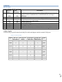
Adapter signals
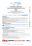
Listed are the pin specifications for the BayTech cable and adapters and the terminal COM ports:
Serial 1: Port Pin out Table
RS-232 Port
(RPC)
1
2
3
4
5
N/C
7
8
9
COM Port
DE-9 Pin
4
7
3
2
6
5
8
4
1
COM Port
DB-25 Pin
20
1
5
2
3
6
7
4
8
22
Signal
DSR
GND
CTS
RXD
TXD
DTR
GND
RTS
DCD
DTR
7 DTR
GND
RTS
TXD
RXD
DSR
GND
CTS
DTR
DCD
RI
RS-232
Port (DS)
1
2
3
4
5
6
7
8
Page
Signal
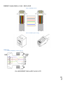
RJ08X007 Standard Rollover Cable – RJ45 to RJ45
Serial 2: RJ08X007 Pin out
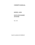
Serial 3: RJ45 Receptacle & Plug
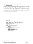
Adapters Serial 4: 9FRJ45PC-1 Adapter Pin Out
Page
8 (Use with RJ08X007 Cable and B/C switch in “B”)
Serial Setup Refer to the Host module user’s manual
NOTE: At any time during the session you need to go to another menu, use the Attention
Character = semi-colon (;). Press the attention character key 5-times to get back to the
main status menu.
NOTE: Password feature is case sensitive. (Default is user/password is root/baytech). If the
DS-RPC login is enabled, the default User Name is ‘admin’; password is ‘baytech’ lower
case or ‘BTA’ upper case for older units.
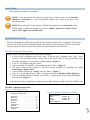
QUICK START: DSRPC For those Administrators who have requested the bare minimum for this type of equipment, follow these
steps exactly. If this is a new unit shipped directly from Baytech, follow the steps. If this is a previously
own unit, perform a factory reset to clear out any users and passwords still in the unit.
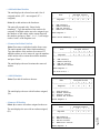
DS2RPC Controller Quick Start Setup the HOST module configuration first, before continuing.
1. If you get only a blinking cursor Press ‘Enter’. If still get only a blinking cursor, Type 5 semicolons (;), The Attention Character will not echo on the screen. There is a one second delay before
the menu is displayed. You should see a menu similar to (Figure 1).
2. Type “C” for configure and press ‘Enter’.
3. Type the number for ‘DS-RPC’ at the prompt and press ‘Enter’, (Figure 2).
4. The outlet control menu, (Figure 3), has three options available to controlling the outlets,
on/off/reboot, (Figures 4/5/6).
5. At the DS-RPC prompt type “config” and press ‘Enter’, (Figure 7).
6. Type “1” at the prompt and press ‘Enter’ to change the password. Default is blank, (Figure 8)
7. Type the Attention Character, Default: semi-colon (;), 5-times quickly to get to the Host module
network menu (Figure 1).
At this point you have enough basic configurations needed to operate the RPC part of the DS-RPC unit.
DS2-RPC explanation quick start
Figure 1: Host Module Menu
Configuration
DS62
module #1.........1
DS74
module #2.........2
DS-RPC
module #3.........3
Enter Request :3
9 Device A
................1
Device B
................2
Device C
................3
Device D
................4
DS-RPC
................5
Configure.......................C
Status..........................S
Unit Reset......................RU
Logout..........................T
Figure 2: Module Configuration Menu
Page
Module:
Attention Character: ]
Figure 3: DS2-RPC Menu Rev F0.15
DS-RPC Power Control
(C) 1997 by BayTech
Rev. F0.15
Circuit Breaker: On
1)...Outlet 1
2)...Outlet 2
3)...Outlet 3
4)...Outlet 4
: On
: On
: On
: On
DS-RPC>
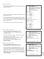
Figure 4: Outlets ON
Type ‘off’ / ‘on’ / ‘reboot’ at prompt and should get the following:
‘off’ = Figure 3; ‘on’ = Figure 4; ‘reboot’ = Figure 5
DS-RPC>off
Turn Off All Outlets (Y/N)?
Figure 5: Outlets Off
DS-RPC>on
Turn On All Outlets (Y/N)?
Figure 6: Outlets Reboot
DS-RPC>reboot
Reboot All Outlets (Y/N)?
NOTE: The reboot option has a 10-second count
down before the outlets turn back on
“9-0 count down”
Figure 7: Configuration Menu
1)...Change Password
2)...Change Outlet Name
3)...Enable/Disable Confirmation
4)...Enable/Disable Status Menu
X)...Exit
Enter Request:
Figure 8: Password
Enter Current Password: ****
Enter new Password:
Re-Enter new Password:
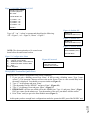
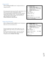
DS4(A)RPC Controller Quick Start Setup the HOST module configuration first, before continuing.
1. If you get only a blinking cursor Press ‘Enter’. If still get only a blinking cursor, Type 5 semicolons (;), The Attention Character will not echo on the screen. There is a one second delay before
the menu is displayed. You should see a menu similar to (Figure 9).
2. Type “C” at the prompt and press ‘Enter’.
3. Type the number for the ‘DS-RPC’ and press ‘Enter’, (Figure 10).
4. Type “1” for Manage Users and press ‘Enter’. (Figure 11)
5. IMPORTANT: the first user added will be the ADMIN user. Type ‘A’ and press ‘Enter’, (Figure
12) Type a name for the admin user. Type the number of the user, just added. Add the outlets.
6. Press ‘Enter’ until you get to the Host module menu (Figure 9).
Page
10 At this point you have enough basic configurations needed to operate the RPC part of the DS-RPC unit.
Figure 9: Host Module Menu
Module:
Attention Character: ]
Device A
................1
Device B
................2
Device C
................3
Device D
................4
DS-RPC
................5
Configure.......................C
Status..........................S
Unit Reset......................RU
Logout..........................T
Enter Request :c
Figure 10: Module Configuration Menu
Configuration
DS62
module #1.........1
DS74
module #2.........2
DS-RPC
module #3.........3
Enter Request :3
Figure 11: DS-RPC Configuration Menu
1)...Manage Users
2)...Change Outlet Name
3)...Enable/Disable Confirmation
4)...Enable/Disable Status Menu
5)...Change Unit ID
6)...Change Alarm Threshold
X)...Exit
Enter Request :1
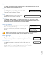
Type the letter “A” at the prompt to add a
user.
Type the name of user.
Select number of user.
Figure 12: Add User Menu
--------------------------------------------|
User
|
Assigned Outlets
|
|
| 1 | 2 | 3 | 4 |
----------------------------------------------------------------------------------------A)...Add User
D)...Delete User
R)...Rename User
Enter user number to assign Outlets, A, D or R.
Enter Request: a
Enter user name: engineer
--------------------------------------------1)...engineer
| N | N | N | N |
--------------------------------------------A)...Add User
D)...Delete User
R)...Rename User
Enter user number to assign Outlets, A, D or R.
Enter Request: 1
1)...Add Outlet(s)
2)...Remove Outlet(s)
3)...Add All Outlets
4)...Remove All Outlets
Enter Outlet number(s): 1,3
11 Enter Request: 1
Page
Type “1” or “3” to add outlets.
--------------------------------------------|
User
|
Assigned Outlets
|
|
| 1 | 2 | 3 | 4 |
--------------------------------------------|
engineer
| N | N | N | N |
---------------------------------------------
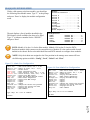
Detail Operations and Configurations DS2RPC Opening Menu A valid connect to the host module, you should get the
following menu.
The Configuration menu displays a list of modules
installed in the DS2 chassis. Type “3” for the “DSRPC”, and press ‘Enter’
NOTE: Module #1 in slot 1 is the Host module.
Module #2 in slot 2 is the DS74 module. Refer to
the individual Host and DS74 module for their
configuration.
Module:
Attention Character: ]
Device A
................1
Device B
................2
Device C
................3
Device D
................4
DS-RPC
................5
Configure.......................C
Status..........................S
Unit Reset......................RU
Logout..........................T
Configuration
DS62
DS74
DS-RPC
module #1..........1
module #2..........2
module #3..........3
DS2RPC CONFIGURATION MENU DS-RPC Power Control
(C) 1997 by BayTech
Rev. F0.15
1)...Change Password
2)...Change Outlet Name
3)...Enable/Disable Confirmation
4)...Enable/Disable Status Menu
X)...Exit
Enter Request: 1
Change Password Select 1), to change the “Admin” user password.
If the Admin has a password, enter the current
password before entering the new password.
Enter new Password:
Re-Enter new Password:
Enter Current Password:
Enter new Password:
Re-Enter new Password:
Change Outlet Name Enter Request:4
Enter :
Type the new name up to 16 characters
1
2
3
4
12 Type the number of the outlet to be changed. If you want to change the name
of Outlet 4, type the number 4 at the “Enter Request” prompt, and press
‘Enter’ The unit displays the following:
1)...Outlet
2)...Outlet
3)...Outlet
4)...Outlet
Page
Select 2), to change the names of the outlets. The unit will display a list of the
outlet’s names.
If the unit displays the following: Type “Y” for yes to change the outlet
name and type the new name.
Type “N” to keep the same outlet name.
Current Outlet: Outlet 4
Modify (Y/N)? Y
Enter:
Enable/Disable Confirmation Select 3), to enable or disable the confirmation option.
If the enable/disable feature is disabled, the DS will not ask to confirm
the command.
From the configuration menu, select “Enable/Disable Confirmation.”
Depending on the current status of the switch, the DS responds with the
option to change the current status. Default is Enabled.
Disable Confirmation (Y/N)? Y
Enable/Disable Status Menu Select 4), to enable or disable the status menu. The DS displays the
following:
Disable Status Menu (Y/N)? Y
If the Enable/Disable Status Menu feature is disabled, only the DS>
prompt appears, else the following status menu appears.
Default is Enabled.
DS2RPC Receptacle Controls On, Off, Reboot On, Off, Reboot, Lock, and Unlock are commands to control the
individual outlets. From the (DS-RPC >) prompt, enter one of the
following commands: {ON n}, {OFF n}, {REBOOT n}, where “n” is the
outlet number you want to command.
Circuit Breaker: On
Example: To turn ‘On’ Outlet 3, type “ON 3” from the DS-RPC prompt.
The DS responds with:
DS-RPC>
1)...Outlet
2)...Outlet
3)...Outlet
4)...Outlet
1
2
3
4
:
:
:
:
On
On
On
On
Turn On Outlet 3 (Y/N)?
Type “Y” for yes turns ‘On’ Outlet 3. Observe the status of Outlet 3 has changed to ‘On’ in the status
menu. Likewise, typing ‘ON ALL’, ‘ON 0’, or ‘ON’ at the DS-RPC > prompt and responding “Y” for
yes, turns ‘On’ all outlets. The {OFF n} command work similarly as the {ON n} command.
The {REBOOT n} command will reboot or reset equipment attached to corresponding receptacle(s).
When the command to REBOOT is sent from the DS-RPC > prompt, the DS powers ‘Off’ the
corresponding outlet(s) for approximately 10 seconds, then powers them ‘On’ in sequence.
This command only works on outlets which were ‘On’ prior to receiving the reboot command
Page
13 NOTE: Type the Attention Character, Default: semi-colon (;), 5-times quickly, to get out of the DS-RPC
module.
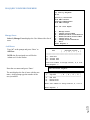
DS4(A)RPC OPENING MENU With a valid connect to the host module; you should get
the following Host Module menu. Type “C” at the prompt
and press ‘Enter’ to display the module configuration
menu.
The unit displays a list of modules installed in the
DS4 chassis, not all available slots have to be filled.
Type “5” or whatever number list the “DS-RPC”,
and press ‘Enter’
Module:
Attention Character: ;
Device A
................1
Device B
................2
Device C
................3
Device D
................4
DS-RPC
................5
Configure.......................C
Status..........................S
Unit Reset......................RU
Logout..........................T
Enter Request :c
Configuration
DS62
DS74
DS74
DS74
DS-RPC
module
module
module
module
module
#1..........1
#2..........2
#3..........3
#4..........4
#5..........5
NOTE: Module #1 in slot 1 is for the Host module. Module #2-4 in slots 2-4 are the DS74Peripheral module which connects to the external devices. Module #5 is the outlet module located
internal to the chassis. Refer to the individual Host and DS74 manuals to configure these modules.
NOTE: Only the Admin user assigned to the First position in the manage users menu will have
the following options available: ‘Config’, ‘Lock’, ‘Unlock’ and ‘Clear’.
Figure 13: Admin User Configuration
On n <cr>
Off n <cr>
Reboot n <cr>
Status <cr>
Config <cr>
Lock n <cr>
Unlock n <cr>
Current <cr>
Clear <cr>
Temp <cr>
Voltage <cr>
Logout <cr>
Logoff <cr>
Exit <cr>
Password <cr>
Whoami <cr>
Unitid <cr>
Help <cr>
--Turn on an Outlet, n=0,1...4,all
--Turn off an Outlet, n=0,1...4,all
--Reboot an Outlet, n=0,1...4,all
--DS-RPC Status
--Enter configuration mode
--Locks Outlet(s) state, n=0,1...4,all
--Unlock Outlet(s) state, n=0,1...4,all
--Display True RMS Current
--Reset the maximum detected current
--Read current temperature
--Display True RMS Voltage
--Logoff
--Logoff
--Logoff
--Changes the current user password
--Displays the current user name
--Displays the unit ID
--This Command
Figure 14: Non-Admin User Configuration
On n <cr>
Off n <cr>
Reboot n <cr>
Status <cr>
Current <cr>
Temp <cr>
Voltage <cr>
Logout <cr>
Logoff <cr>
Exit <cr>
Password <cr>
Whoami <cr>
Unitid <cr>
Help <cr>
--Turn on an Outlet, n=0,1...4,all
--Turn off an Outlet, n=0,1...4,all
--Reboot an Outlet, n=0,1...4,all
--DS-RPC Status
--Display True RMS Current
--Read current temperature
--Display True RMS Voltage
--Logoff
--Logoff
--Logoff
--Changes the current user password
--Displays the current user name
--Displays the unit ID
--This Command
Type "Help" for a list of commands
Type "Help" for a list of commands
DS-RPC>
Page
14 DS-RPC>
DS4(A)RPC CONFIGURATION MENU DS-RPC Series
(C) 2001 by BayTech
F2.05
Option(s) Installed:
True RMS Current
Internal Temperature
True RMS Voltage
Unit ID: Site Alpha
Manage Users Select 1) Manage Users displays the User Menu with a list of
users.
1)...Manage Users
2)...Change Outlet Name
3)...Enable/Disable Confirmation
4)...Enable/Disable Status Menu
5)...Change Unit ID
6)...Change Alarm Threshold
X)...Exit
Enter Request:1
Add Users Type “A” at the prompt and press ‘Enter’ to
Add User.
NOTE: the first assigned user will be the
‘admin user’ for the outlets.
--------------------------------------------|
User
|
Assigned Outlets
|
|
| 1 | 2 | 3 | 4 |
----------------------------------------------------------------------------------------A)...Add User
D)...Delete User
R)...Rename User
Enter user number to assign Outlets, A, D or R.
Enter Request: a
--------------------------------------------1)...engineer
| N | N | N | N |
--------------------------------------------A)...Add User
D)...Delete User
R)...Rename User
Enter user number to assign Outlets, A, D or R.
Enter Request: 1
15 The unit displays the list of users with the new
name. At the prompt type the number of the
user just added.
Enter user name: Engineer
Page
Enter the user name and press ‘Enter’.
Add Individual Outlets The unit displays the selected user and a list of
assigned outlets. (‘N’ = not assigned; ‘Y’ =
assigned).
Select 1) to add outlets to the listed user.
The unit will respond with, “Enter Outlet
number(s)”: Type the number of the outlet to be
assigned. If multiple outlets are to be assigned, type
the numbers of the outlets with a comma between
the numbers and press ‘Enter’, i.e. (1, 3) will assign
outlets 1 and 3 to the Engineer user.
--------------------------------------------|
User
|
Assigned Outlets
|
|
| 1 | 2 | 3 | 4 |
--------------------------------------------|
Engineer
| N | N | N | N |
--------------------------------------------1)...Add Outlet(s)
2)...Remove Outlet(s)
3)...Add All Outlets
4)...Remove All Outlets
Enter Request: 1
Enter Outlet number(s): 1, 3
Remove Individual Outlets Select 2) to remove individual outlets from a user.
The unit responds with ‘Enter Outlet number(s):’
Type the number of the outlet to be removed. If
multiple outlets are to be removed, type the numbers
of the outlets with a comma between the numbers
and press ‘Enter’,
The unit displays the user list minus the removed
outlets.
--------------------------------------------|
User
|
Assigned Outlets
|
|
| 1 | 2 | 3 | 4 |
--------------------------------------------|
Engineer
| Y | N | Y | N |
--------------------------------------------1)...Add Outlet(s)
2)...Remove Outlet(s)
3)...Add All Outlets
4)...Remove All Outlets
Enter Request: 2
Enter Outlet number(s): 1
Add All Outlets Select 3) to add all outlets to the user.
--------------------------------------------|
User
|
Assigned Outlets
|
|
| 1 | 2 | 3 | 4 |
--------------------------------------------|
Engineer
| N | N | Y | N |
---------------------------------------------
The unit displays the user with all outlets assigned,
(Y).
1)...Add Outlet(s)
2)...Remove Outlet(s)
3)...Add All Outlets
4)...Remove All Outlets
Enter Request: 3
1)...Add Outlet(s)
2)...Remove Outlet(s)
3)...Add All Outlets
4)...Remove All Outlets
Enter Request: 4
16 The unit displays the user with no outlets assigned,
(N).
--------------------------------------------|
User
|
Assigned Outlets
|
|
| 1 | 2 | 3 | 4 |
--------------------------------------------|
Engineer
| Y | Y | Y | Y |
---------------------------------------------
Page
‐‐‐Remove All Outlets Select 4) to remove all outlets assigned to the user.
Delete User Select D) from the Manage Users menu to Delete
User.
--------------------------------------------|
User
|
Assigned Outlets
|
|
| 1 | 2 | 3 | 4 |
--------------------------------------------|
Engineer
| N | N | N | N |
--------------------------------------------A)...Add User
D)...Delete User
R)...Rename User
The unit responds with ‘Enter the user number to
delete’. Type the number and press ‘Enter’.
Enter Request: d
Enter the user number to delete: 1
You are deleting the current admin user. The
next user will become the admin user, do you
want to continue. (Y/N)? y
The unit displays the user list minus the deleted
user.
--------------------------------------------|
User
|
Assigned Outlets
|
|
| 1 | 2 | 3 | 4 |
----------------------------------------------------------------------------------------A)...Add User
D)...Delete User
R)...Rename User
Enter user number to assign Outlets, A, D or R.
Enter Request:
Rename User The unit responds with ‘Enter user name:’. Type
the new name and press ‘Enter’.
The unit displays the user list with the renamed
user.
Enter user number to assign Outlets, A, D or R.
Enter Request: r
Enter the user number to rename: 1
Enter user name: Engineer
--------------------------------------------|
User
|
Assigned Outlets
|
|
| 1 | 2 | 3 | 4 |
--------------------------------------------1)...Engineer
| N | N | N | N |
--------------------------------------------A)...Add User
D)...Delete User
R)...Rename User
Enter user number to assign Outlets, A, D or R.
Enter Request:
17 The unit responds with ‘Enter the user number to
rename:’. Type the number and press ‘Enter’.
--------------------------------------------|
User
|
Assigned Outlets
|
|
| 1 | 2 | 3 | 4 |
--------------------------------------------1)...Tester
| N | N | N | N |
--------------------------------------------A)...Add User
D)...Delete User
R)...Rename User
Page
Select R) from the Manage Users menu to
Rename User.
Change Outlet Name Select 2) Change Outlet Name from the Configuration Menu
to rename the outlets.
The unit responds with a list of outlets. Type the number of an
outlet and press ‘Enter’.
The unit responds with the Current Outlet name and ‘Modify
(Y/N)?’ Type “Y” for yes to change the outlet name and press
‘Enter’. Type the new name. Type “N” to keep the same outlet
name and press ‘Enter’.
The unit displays the outlet list with the renamed outlet.
1)...Manage Users
2)...Change Outlet Name
3)...Enable/Disable Confirmation
4)...Enable/Disable Status Menu
5)...Change Unit ID
6)...Change Alarm Threshold
X)...Exit
Enter Request: 2
1)...Outlet
2)...Outlet
3)...Outlet
4)...Outlet
1
2
3
4
Enter Request: 1
Current Outlet: Outlet
Modify (Y/N)? y
1
Enter : Tester 1
1)...Tester 1
2)...Outlet 2
3)...Outlet 3
4)...Outlet 4
Enter Request:
Enable/Disable Confirmation Select 3) Enable/Disable Confirmation from the
Configuration Menu to enable a confirmation prior to
executing command.
If the unit responds with ‘Enable Confirmation (Y/N)?’, The
Confirmation is currently disabled.
If the unit responds with ‘Disable Confirmation (Y/N)?’,
The Confirmation is currently enabled.
Type “Y” for yes or “N” for no and press ‘Enter’.
Default is Enabled.
1)...Manage Users
2)...Change Outlet Name
3)...Enable/Disable Confirmation
4)...Enable/Disable Status Menu
5)...Change Unit ID
6)...Change Alarm Threshold
X)...Exit
Enter Request: 3
Enable Confirmation (Y/N)? y
Or
Disable Confirmation
(Y/N)? y
Enable/Disable Status Menu 18 If the unit responds with ‘Enable Status Menu (Y/N)?’. The
Status Menu is currently disabled. If the unit responds with
‘Disable Status Menu (Y/N)?’. The Status Menu is currently
enabled. Type “Y” for yes or “N” for no and press Enter’. A
Disabled Status Menu is display only the prompt: “DS-RPC>’
Default is Enabled.
1)...Manage Users
2)...Change Outlet Name
3)...Enable/Disable Confirmation
4)...Enable/Disable Status Menu
5)...Change Unit ID
6)...Change Alarm Threshold
X)...Exit
Enter Request: 4
Enable Status Menu (Y/N)? y
Or
Disable Status Menu
(Y/N)? y
Page
Select 4) Enable/Disable Status Menu from the
Configuration Menu to enable outlet status menu
Change Unit ID Select 5) Change Unit ID from the Configuration Menu to
change the unit ID.
The unit responds with ‘Current Unit ID:’ and ‘Modify (Y/N)?
Type “Y” for yes or “N” for no and press ‘Enter’.
If yes the unit responds with ‘Enter New Unit ID:’ Type new
name for the ID and press ‘Enter’. The unit responds with
“Unit ID: (Name). In the screen shot, the current ID was
blank. The new ID is “Site Alpha”
Default is Blank(No Name Entered).
1)...Manage Users
2)...Change Outlet Name
3)...Enable/Disable Confirmation
4)...Enable/Disable Status Menu
5)...Change Unit ID
6)...Change Alarm Threshold
X)...Exit
Enter Request: 5
Current Unit ID:
Modify (Y/N)? y
Enter New Unit ID: Site Alpha
Unit ID: Site Alpha
Change Alarm Threshold Buzzer alarm value :
12.0 Amps
Modify (Y/N)? y
Enter: 13
19 The unit responds with current ‘Buzzer alarm value:’ and
‘Modify (Y/N)? Type “Y” for yes or “N” for no and press
‘Enter’.
If yes the unit responds with ‘Enter:’ Type new value and
press ‘Enter’. To verify the changes, Select 6) from the
Configuration Menu. Default is 12.0 Amps.
1)...Manage Users
2)...Change Outlet Name
3)...Enable/Disable Confirmation
4)...Enable/Disable Status Menu
5)...Change Unit ID
6)...Change Alarm Threshold
X)...Exit
Enter Request: 6
Page
Select 6) Change Alarm Thresholds from the Configuration
Menu to the over current alarm levels.
DS4(A)RPC OUTLET CONTROL From the Host Module Menu, Select the number
corresponding to the DS-RPC, in this screen shot the
number is “5”.
The DS-RPC module displays the following menu below.
Outlet Default is ON.
Device A
................1
Device B
................2
Device C
................3
Device D
................4
DS-RPC
................5
Configure.......................C
Status..........................S
Unit Reset......................RU
Logout..........................T
Enter Request: 5
DS-RPC Series
(C) 2001 by BayTech
F2.05
Option(s) Installed:
True RMS Current
Internal Temperature
True RMS Voltage
Unit ID: Site Alpha
Average Power: 0 Watts
Apparent Power: 26 VA
True RMS Voltage: 120.5 Volts
True RMS Current: 0.1 Amps Maximum Detected: 0.2 Amps
Internal Temperature: 29.5 C
Outlet Circuit Breaker: Good
Type “Help” at the prompt for a list of
Outlet Controller commands
1)...Tester 1
2)...Outlet 2
3)...Outlet 3
4)...Outlet 4
:
:
:
:
On
On
On
On
Type "Help" for a list of commands
DS-RPC>help
On n <cr>
Off n <cr>
Reboot n <cr>
Status <cr>
Config <cr>
Lock n <cr>
Unlock n <cr>
Current <cr>
Clear <cr>
Temp <cr>
Voltage <cr>
Logout <cr>
Logoff <cr>
Exit <cr>
Password <cr>
Whoami <cr>
Unitid <cr>
Help <cr>
--Turn on an Outlet, n=0,1...4,all
--Turn off an Outlet, n=0,1...4,all
--Reboot an Outlet, n=0,1...4,all
--DS-RPC Status
--Enter configuration mode
--Locks Outlet(s) state, n=0,1...4,all
--Unlock Outlet(s) state, n=0,1...4,all
--Display True RMS Current
--Reset the maximum detected current
--Read current temperature
--Display True RMS Voltage
--Logoff
--Logoff
--Logoff
--Changes the current user password
--Displays the current user name
--Displays the unit ID
--This Command
DS-RPC>
20 Type "Help" for a list of commands
Page
NOTE: Only the Admin user will
have the {Config}, {Lock n},
{Unlock n}, or {Clear} options
available.
DS4(A)RPC Receptacle Controls: On, Off, Reboot, Lock, and Unlock On, Off, Reboot, Lock, and Unlock are commands to control the
individual outlets. From the (DS-RPC >) prompt, enter one of the
following commands: {ON n}, {OFF n}, {REBOOT n}, where “n” is the
outlet number you want to command.
Circuit Breaker: On
Example: To turn ‘On’ Outlet 3, type “ON 3” from the DS-RPC prompt.
The DS responds with:
DS-RPC>on 3
1)...Outlet
2)...Outlet
3)...Outlet
4)...Outlet
1
2
3
4
:
:
:
:
On
On
On
On
Turn On Outlet 3 (Y/N)?y
Type “Y” for yes turns ‘On’ Outlet 3. Observe the status of Outlet 3 has changed to ‘On’ in the status
menu. Likewise, typing ‘ON ALL’, ‘ON 0’, or ‘ON’ at the DS-RPC > prompt and responding “Y” for
yes, turns ‘On’ all outlets. The {OFF n} command work similarly as the {ON n} command.
The {REBOOT n} command will reboot or reset equipment attached to corresponding receptacle(s).
When the command to REBOOT is sent from the DS-RPC > prompt, the DS powers ‘Off’ the
corresponding outlet(s) for approximately 10 seconds, then powers them ‘On’ in sequence.
This command only works on outlets which were ‘On’ prior to receiving the reboot command
The {Lock n} command will lock the outlet in its current state, On or Off. The {Unlock n} command
unlocks the outlets to allow them to change states, On, Off, or Reboot.
NOTE: Only the Admin user will have the {Lock n} and {Unlock n} options.
Status This shows the current status of
the unit RPC: Voltage, RMS
Current, Maximum Detected
Current, state of circuit breaker,
Average Power, Apparent Power
and Internal Temperature.
Average Power:
0 Watts
Apparent Power:
29 VA
True RMS Voltage: 121.1 Volts
True RMS Current:
0.2 Amps
Internal Temperature:
Maximum Detected:
0.2 Amps
33.5 C
Outlet Circuit Breaker: Good
1)...Tester 1
2)...Test 2
3)...Outlet 3
4)...Outlet 4
:
:
:
:
On
On
On
On
Config Refer to previous section on DS4 (A)-RPC CONFIGURATION MENU.
Current DS-RPC>current
0.2 Amps
Maximum Detected:
Type "Help" for a list of commands
0.2 Amps
21 True RMS Current:
Page
Type “Current” at the prompt to show
the unit’s True RMS Current and Peak
RMS Current, and the unit will display
the following:
Clear Type “Clear” at the prompt to reset the Maximum Detected, the unit will redisplay the status menu with
the new maximum detected current. Admin user only
Voltage True RMS Voltage: 122.2 Volts
Type “Voltage” at the prompt to display the unit’s True RMS
Voltage, and the unit will display the following.
Temp Type “Temp” at the prompt to show the unit’s current
temperature, the units will display the following:
Internal Temperature:
33.5 C
Logging Out Type “Logout”, “Logoff”, or “Exit” at the prompt to logoff from the unit. This will close the Outlet
Control session. Press “Enter” to open the Outlet Controller session. A login prompt may appear if a user
has been assign to an outlet. Newer firmware may go to the network menu.
Current User Password: Type “Password” at the prompt to change the current user’s password
and the unit will display the following:
If the current user already has a password the unit will display the
following:
Enter new Password:
Re-Enter new Password:
Enter old Password:
Enter new Password:
Re-Enter new Password:
NOTE: If you do not have the user’s current password, delete the user. Reinstall user. Select
option to change password and the unit will respond asking for a new password
Identify Current User Type “Whoami” at the prompt to determine the current user, the unit displays the
following:
To change the user, logout of the unit and log back in using the new user name.
Current User: root
Unit Identification Type “unitid” at the prompt to determine the Unit ID, the MRP displays the
following:
Unit ID: DS4-RPC
Page
22 To change the unit ID, go the Outlet Configuration menu and select ‘Change Unit
ID’ option. The maximum field length is 32 or 16 for older units.
BayTech Product Warranty Bay Technical Associates (BayTech) warrants that its products will be free from defects in materials and
workmanship under normal use for a period of two years from date of purchase (or from date of shipment
from BayTech if proof of purchase is not provided).
During this warranty period, BayTech shall, at its discretion, either repair or exchange any defective
product at no charge for labor and materials, or refund the amount paid for the product, less shipping and
handling charges. Any replacement and/or repaired products are warranted for the remainder of the
original warranty.
The customer is responsible for properly packaging the product and for shipping costs for returns. The
customer is liable for loss or damage to the product during shipping, as well as any other fees or charges
associated with transporting the product back to BayTech. BayTech will pay return costs for delivery
within the Continental United States.
All repair and return shipments must be approved by BayTech and must be accompanied by an RA
(return authorization) number. Please refer to our Repair and Return Policy below.
For the initial 30 days from the original date of shipment, any unopened product may be returned to
BayTech, accompanied by an RA number. Full purchase price will be refunded, provided that the product
is in excellent condition. A product may not be returned after 30 days from the original date of shipment
unless approved by BayTech management.
For additional information or more specific warranty issues, contact BayTech’s Technical Support or
Customer Service Departments at (800) 523-2702 or (228) 563-7334.
Exceptions This warranty does not cover misuse or minor imperfections that fall within design specifications or that
do not materially alter functionality. BayTech does not warrant and is not responsible for damages
incurred in shipping and handling or caused by disasters (such as fire, flood, wind, earthquake, lightning,
power surges or water).
The warranty will be voided regarding products that have been neglected, altered, abused, misused, or
used for purposes other than those for which it was designed.
Under no circumstances shall BayTech be liable for any special, incidental, or consequential damages
based upon breach of warranty, breach of contract, negligence, strict liability, or any other legal theory.
Such damages include (but are not limited to) loss of profits, loss of the product or associated equipment,
cost of capital, cost of substitute or replacement equipment, facilities or services, down time, purchaser’s
time, the claims of third parties, including customers, and injury to property.
BayTech Extended Warranty Page
23 Extended warranties and but only at the time of product purchase. The extended warranty cost will not
exceed 7% per year of the product list price unless otherwise stated in the customer contract or approved
by BayTech management. Contact BayTech for further details on this.
Technical Support BayTech offers Tech Support for the lifetime of the product. A staff of Applications Engineers is on
duty to assist with installation, set up or operation issues. Support is available from 8:00 a.m. to 5 p.m.
(CST or CDT), Monday through Friday at the phone numbers or website provided below.
Please have the following information available to help the Applications Engineers answer questions
efficiently:
BayTech model type
Unit serial number
Firmware version (if accessible)
A list of devices connected to the BayTech unit
A general description of the application being used and the intended outcome
Information about cables and adapters being used (type, length, place of purchase)
The name of the software emulation program being used
Printout of the configuration status (if possible)
Bay Technical Associates, Inc.
5239 A Avenue
Long Beach Industrial Park
Long Beach, MS 39560
Telephone: 800-523-2702 or 228.563.7334
FAX: 228.563.7335
Email: [email protected]
Website: www.baytech.net
Repair Policy (Return policy refers to BayTech products purchased and returned for credit or repair.)
A Return Authorization (RA) number must be obtained in all cases before returning the BayTech
product. Have the serial number and reason for the return or description of the problem handy.
Customers in the Continental U.S. can call 1-800-523-2702 or international customers can call
228.563.7334 to obtain an RA number.
Before dismantling equipment or returning the unit for any reason, always contact BayTech. Attempting
to repair a product without BayTech authorization may result in voiding the warranty.
Cost and Time:
The cost of repair for units no longer under warranty will be $50.00 per hour plus cost of materials and
shipping. Typical turnaround times for repairs are 3 days for domestic requests and 5 days for
international.
Page
24 Follow the instructions below for repackaging and shipping. NOTE: Power should be disconnected
from the power source before servicing or dismantling.
Return Authorization Process: a. Contact BayTech via Phone, Fax, or Email to get a Return Authorization (RA) Number.
IMPORTANT: BayTech will not accept any returns without an RA number.
b. Package the unit carefully in its original packaging or similar packaging. The warranty does not
cover damage sustained during shipment. Enclose a letter with name, address, RA number,
daytime phone number and description of the problem.
c. Mark the RA number clearly on the outside of the package.
d. Ship the unit by insured, prepaid carrier to the following address:
Page
25 Bay Technical Associates
5239 A Avenue
Long Beach Industrial Park
Long Beach, MS 39560
RA #: 140-xxxxx