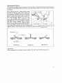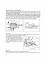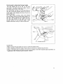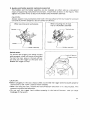
1
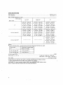
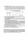
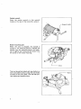
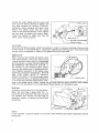
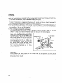
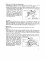
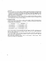
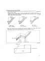
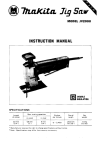
Slide Compound Saw
305 mm (12”) MODEL L S l 2 1 l
Equipped with Electric Brake
INSTRUCTION MANUAL
DOUBLE
INSULATION
SPECIFICATIONS
Blade diameter
..............................................................................................................
305 mm 112")
Arbor diameter
..............................................................................................................
25.4 mm 11")
Max cutting capacities 1H x W )
Bevel angle
Left 45"
00
I
Right 45"
00
65 mm x 230 mm
12-9/16" x 9-1/16',)
49 mm x 230 mm
*11-15/16" x 9-1/16',)
.120 mm x 230 mm
14-3/4" x 9-1/16',)
57 mm x 290 mm
12-1/4" x 11-7/16")
40 mm x 290 mm
11-9/16" x 11-7/16")
107 mm x 290 mm
14-3/16" x 11-7/16")
48 mm x 310 mm
11-7/8" x 12-3/16")
31 mm x 310 mm
11-1/4" x 12-3/16")
94 mm x 310 mm
13-11/16" x 12-3/16")
65 mm x 162 mm
12-9/16'' X 6-3/8"1
49 mm x 162 mm
11-15/16" x 6-3/8"1
.120 mm x 162 mm
(4-3/4" x 6-3/8"1
57 mm x 205 mm
(2-1/4" x 8-1/16',)
4 0 mm x 205 mm
11-9/16" x 8-1/16',)
107 mm x 205 mm
14-3/16" x 8-1/16")
48 mm x 219 mm
.11-7/8" x 8-5/8")
31 mm x 219 mm
11-1/4" x 8 - 5 / 8 " )
94 mm x 219 mm
13-11/16" x 8-5/8")
.
Miter angle
.
Left and right 45O
1
-120mmx 115mm
(4-3/4" x 4-112")
107 mm x 145 mm
14-3/16' x 5-1 1/16',)
94 mm x 155 mm
13-11/16" x 6-118"l
[Note)
mark indicates that a w o o d facing w i t h t h e following thickness is used.
I
I
Miter angle
I
oo
Left and right 45O
No load speed (RPMl
Thickness of wood facing
30 mm 11-3/16',)
I
21 mm 113/16"1
................................................................................................................
Dimensions (L x W x HI
..............................
4,000
.._.1,040 mm x 605 mm x 620 mm
140-15/16" x 23-13/16" x 24-7/16,')
Net weight .......................
Manufacturer reserves t h e right t o change specifications w i t h o u t notice.
Note: Specifications may differ f r o m c o u n t r y t o country.
WARNING: For your personal safety, READ and UNDERSTAND before using.
SAVE THESE INSTRUCTIONS FOR FUTURE REFERENCE.
2
For Your Own Safety Read Instruction
Manual Before Operating
Slide Compound Saw
Save it for future reference
GENERAL SAFETY PRECAUTIONS
(For All Tools)
1. KNOW YOUR POWER TOOL. Read the owner’s manual carefully. Learn the
tools applications and limitations, as well as the specific potential hazards
peculiar t o it.
2. KEEP GUARDS I N PLACE and in working order.
3. REMOVE ADJUSTING
KEYS A N D WRENCHES. Form habit of checking t o
see t h a t keys and adjusting wrenches are removed from tool before turning
it on.
4. KEEP WORK AREA CLEAN. Cluttered areas and benches invite accidents.
5. DON’T USE IN DANGEROUS ENVIRONMENT. Don’t use power tools in damp
or w e t locations, or expose t h e m t o rain. Keep work area well lighted.
Don’t use tool in presence of flammable liquids or gases.
6. KEEP CHILDREN AWAY. All visitors should be kept safe distance f r o m work
area.
7. MAKE WORKSHOP CHILD PROOF with padlocks, master switches, or by
removing starter keys.
8. DON‘T FORCE TOOL. It w i l l do the job better and safer at the rate for w h i c h
it was designed.
9. USE RIGHT TOOL. Don’t force tool or attachment to d o a job for w h i c h it
was n o t designed.
IO. WEAR
PROPER APPAREL. Wear no loose clothing, gloves, neckties, rings,
bracelets, or other jewelry w h i c h may get caught in moving parts. Nonslip
footwear is recommended. Wear protective hair covering t o contain long hair.
11. ALWAYS USE SAFETY GLASSES. Also use face or dust mask if cutting
operation is dusty. Everyday eyeglasses only have impact resistant lenses,
they are NOT safety glasses.
12. SECURE WORK. Use clamps or a vise t o hold work w h e n practical. It’s safer
than using your hand and it frees both hands t o operate tool.
13. DON‘T OVERREACH. Keep proper footing and balance at all times.
14. MAINTAIN TOOLS WITH CARE. Keep tools sharp and clean for best and
safest performance. Follow instructions for lubricating and changing accessories.
15. DISCONNECT TOOLS before servicing, w h e n changing accessories such as
blades, bits, cutters, and the like.
3
16. EXTENSION CORDS. Make sure your extension cord is i n good condition.
When using an extension cord, be sure to use one heavy enough to carry
the current your product w i l l draw. An undersized cord will cause a drop
in line voltage resulting in loss of power and overheating. Table 1 shows the
correct size to use depending on cord length and nameplate ampere rating.
If in doubt, use the next heavier gauge. The smaller the gauge number, the
heavier the cord.
TABLE 1 MINIMUM GAUGE FOR CORD SETS
Total Length of Cord in Feet
I
0 - 25
I
26 - 50
Ampere Rating
More
Not M O W
Than
Than
0
-
6
-
10
12
-
6
10
12
16
I
51
-
100
I
101
-
150
A W G
18
18
16
14
16
16
16
12
:t
I
14
12
14
12
Not Recommended
VOLTAGE WARNING: Before connecting the tool t o a power source (receptacle,
outlet, etc.) be sure the voltage supplied is the same as t h a t specified o n the
nameplate of the tool. A power source w i t h voltage greater than t h a t specified
for the tool can result i n SERIOUS INJURY t o the user - as well as damage t o
the tool. If in doubt, DO NOT PLUG IN THE TOOL. Using a power source w i t h
voltage less than the nameplate rating is harmful t o the motor.
ADDITIONAL SAFETY RULES
1. Wear eye protection.
2. Do n o t operate saw without guards in place.
3. Don't use the t o o l i n the presence of flammable liquids or gases.
-
4. Check the blade carefully for cracks or damage before operation.
Replace cracked or damaged blade immediately.
5. Use only flanges specified for this tool.
6. Be careful not t o damage the arbor, flanges (especially the installing surface)
or bolt. Damage t o these parts could result in blade breakage.
7. Make sure that the turn base is properly secured so it w i l l not move during
operation.
8. For your safety, remove the chips, small pieces, etc. from the table top before
operation.
9. Avoid cutting nails. Inspect for and remove all nails from the workpiece before
operation.
IO. Make sure the shaft lock is released before the s w i t c h is turned on.
1 1. Be sure that the blade does not contact the turn base in the lowest position.
12. Hold the handle firmly. Be aware that the saw moves u p or d o w n slightly
during start-up and stopping.
13. Do not perform any operation freehand. The workpiece must be secured
firmly against the turn base and guide fence w i t h the vise during all
operations. Never use your hand t o secure the workpiece.
14.Keep hands out of path of saw blade. Avoid contact w i t h any coasting blade.
It can still cause severe injury.
15. Never reach around saw blade.
16. Make sure the blade is not contacting the workpiece before the s w i t c h is
turned on.
17. Before using the tool o n an actual workpiece, let it run for a while. Watch
for vibration or wobbling that could indicate poor installation or a poorly
balanced blade.
18. Wait until the blade attains full speed before cutting.
19. Stop operation immediately i f you notice anything abnormal.
20. Do n o t attempt t o lock the trigger in the o n position.
21. Shut o f f power and wait for saw blade t o stop before servicing or adjusting
tool.
22. Be alert at all times, especially during repetitive, monotonous operations.
Don't be lulled into a false sense of security. Blades are extremely unforgiving.
23. Always use accessories recommended i n this manual. Use of improper
accessories such as abrasive wheels may cause an injury.
24. Don't abuse cord. Never yank cord t o disconnect it from the receptacle. Keep
cord away f r o m heat, oil, water and sharp edges.
SAVE THESE INSTRUCTIONS.
5
Socket wrench
Store the socket wrench in the wrench
holder a t the rear of the tool after using it.
Wrench holder
1
Bench mounting saw
,
When the tool is shipped, the handle is
locked in the lowered position. Release the
handle from the lowered position by lowering it slightly and removing the chain from
the screw on the motor housing.
I
I
I
This tool should be bolted with two bolts to a
level and stable surface using the bolt holes
provided in the tool’s base. This will help prevent tipping and possible injury.
6
Chain
Installing or removing saw blade
CAUTION :
Always be sure that the tool is switched off and unplugged before installing or removing
the blade.
Use the socket wrench to loosen the hex
bolt which secures the center cover by
turning counterclockwise. Raise the safety
cover and the center cover.
Socket wrenc
Press the shaft lock to lock the spindle
and use the socket wrench to loosen the
hex bolt by turning it clockwise. Then remove the hex bolt, outer flange and blade.
Hex bolt (left-handed)
Socket wrench
To install the blade, mount it carefully
onto the spindle, making sure that the
direction of the arrow on the surface of the
blade matches the direction of the arrow
on the blade case.
\-Outer
flange
rSpindle
Ring
Inner flange
Saw blade
I - -
Hex bolt (left-handed)
7
Install the outer flange and hex bolt, and
then use the socket wrench to tighten the
hex bolt securely by turning it counterclockwise while pressing the shaft lock.
Return the safety cover and the center
cover to the original position. Then tighten
the hex bolt to secure the center cover.
Lower the handle to make sure that the
safety cover moves properly.
I
I
/-Safety
-Socket
cover
wrench
CAUTION:
Use only the Makita socket wrench provided to install or remove the blade. Failure to do
so may result in overtightening or insufficient tightening of the hex bolt. This could cause
serious injury to operator or others in the general vicinity of the tool.
Safety cover
-When lowering the handle, the safety cover
rises automatically. The cover returns to i t s
original position when the cut is complet d
and the handle is raised. NEVER DEFE&T
OR REMOVE THE SAFETY COVER. In
the interest of your personal safety, always
maintain the safety cover in good condition.
Any irregular operation of the safety cover
should be corrected immediately. NEVER
USE THE TOOL WITH A FAULTY
SAFETY COVER. If the see-through safety
cover becomes dirty, or sawdust adheres to
it in sucha way that the blade and/or workpiece is no longer easily visible, unplug the saw and clean the cover carefully with a damp
cloth. Do not use solvents or any petroleum-based cleaners on the plastic cover.
~~
Dust bag
To attach the dust bag, fit i t into the elbow.
When the dust bag is about half full, remove the dust bag from the tool and pull
the fastener out. Empty the dust bag by
tapping it lightly to remove as much dust
as possible.
NOTE :
If you connect a vacuum cleaner to your saw, more efficient and cleaner operations can be
performed.
8
Positioning kerf boards
This tool is provided with kerf boards in the turn base. The kerf boards are factory-adjusted
so that the saw blade does not contact the kerf boards. Before use, adjust the kerf boards
as follows:
First unplug the tool. Loosen the a l l screws
(2 each on left and right) which secure the
kerf boards. Retighten them t o the extent
that the kerf boards can be easily moved by
hand. Loosen the clamp screw on the arm.
Pull the carriage toward you fully and
lower the handle fully. Adjust the kerf
boards so that the kerf boards just contact
the sides of blade teeth slightly. Tighten
the front screws (do not tighten firmly).
Push the carriage toward the guide fence
fully and adjust the kerf boards so that the
kerf boards just contact the sides of blade teeth slightly. Tighten the rear screws (do not
tighten firmly). After adjusting the kerf boards, tighten the a l l screws securely.
1
Kerf board
Left bevel cut
Straight cut
Right bevel cut
CAUTION:
After changing the bevel angle, always readjust the kerf boards as described above.
9
Maintaining maximum cutting capacity
This tool I S factory adjusted to provided the max. cutting capacity for a 305 mm (12”) saw
blade. When using a saw blade other than the 305 mm (12”) saw blade, adjust the lower
limit position of the blade as follows:
First unplug the tool. Push the carriage toward the guide fence fully and lower the handle
completely. Use the socket wrench to turn the adjusting bolt until the periphery of the
blade extends slightly below the top surface of the turn base at the point where the front
face of the guide fence meets the top surface of the turn base. With the tool unplugged,
rotate the blade by hand while holding the handle a l l the way down to be sure that the
blade does not contact any part of the lower base. Re-adjust slightly, if necessary.
I
Periphery
of blade
n
To surface
of turn base
Guide fence
I
I
CAUTION :
After installing a new blade, always be sure that the blade does not contact any Part of
the lower base when the handle is lowered completely.
Positioning for adjusting the miter angle
The turn base turns up to 60” to the left
and right. Loosen the grip and turn the
turn base to the position where the pointer
points to the desired angle on the miter
scale. Then, tighten the grip firmly to secure
turn base.
I
-Miter
scale
CAUTION :
When turning the turn base, be sure to rasie the handle fully.
After changing the miter angle, always secure the turn base by tightening the grip firmly.
10
Positioning for adjusting the bevel angle
The saw blade t i l t s up t o 45" t o the left
and right. To adjust the bevel angle, loosen
the lever a t the rear of the tool.
For left bevel cutting, tilt the saw blade t o
the left until the pointer points t o the desired angle. Then tighten the lever firmly t o
secure the arm.
For right bevel cutting, press the release
button after tilting the saw blade slightly t o
the left. While pressing the release button,
tilt the saw blade t o the right until the
pointer points t o the desired angle. Then
tighten the lever firmly to secure the arm.
i-f-
Tighten
L
CAUTION :
*When tilting the saw blade, be sure to raise the handle fully.
*After changing the bevel angle, always secure the arm by tightening the lever.
*When changing bevel angles, be sure t o position the kerf boards appropriately as
explained in the "Positioning kerf boards" section.
11
Securing workpiece
WARNING:
It i s extremely important to always secure the workpiece properly and tightely with the
vise. Failure to do so can cause the tool to be damaged and/or the workpiece to be destroyed. PERSONAL INJURY MAY ALSO RESULT. Also, after any cutting operation,
DO NOT raise the blade until the blade has come to a complete stop.
1. Vertical vise
The vertical vise can be installed in two
positions on either the left or right side
of the guide fence, or holder assembly
(optional accessory). Insert the vise rod
into the hole in the guide fence or holder
assembly and tighten the screw to secure
the vise rod. (Note: When using the
holder assembly, install it on the holder
(optional accessory) as shown in the
figure.) Position the vise arm according
to the thickness and shape of the workpiece and secure the vise arm by tightenHolder
H k r assembly
ing the screw. Make sure that no part of
the tool contacts the vise when lowering th. handle fully or when pulling or pushing
the carriage. If some part contacts the vise, re-position the vise. Press the workpiece flat
against the guide fence and the turn base. Position the workpiece a t the desired cutting
position and secure it firmly by tightening the clamp screw of the vise. The maximum
thickness of workpieces which can be secured by the vertical vise is 120 mm (4-3/4").
w
CAUTION :
The workpiece must always be secured firmly against the turn base and guide fence with
the vise during all operations.
2. Horizontal vise (optional acccssory)
The horizontal vise can be installed in
two positions on either the left or right
side of the base. When performing 15" or
greater miter cuts, install the horizontal
vise on the side opposite the direction in
which the turn table is to be turned. By
flipping the vise nut to the left, the vise
is released, and rapidly moves in and out.
To grip workpieces, push the vise knob
forward until the vise plate contacts the
workDiece and fliD the vise nirt to the
right.' Then turn the vise knob clockwise to secure the workpiece. The maximum width
of workpieces which can be secured by the horizontal vise is 200 mm (7-7/8").
CAUTION :
Always set the vise nut to the right fully when securing the workpiece. Failure to do so
may result in insufficient securing of the workpiece. This could cause the workpiece to
be thrown, cause damage to the blade or cause the dangerous loss of control of the tool.
12
3. Holders and holder assembly (optional accessories)
The holders and the holder assembly can be installed on either side as a convenient
means of supporting workpieces horiziontally. Install them as shown in the figures. Then
tighten the screws firmly to secure the holders and the holder assembly.
CAUTION :
Always support long workpieces level with the top surface of the turn base for accurate
cuts and to prevent dangerous loss of control of the tuol.
When installing the vertical
vise on the holder assembly
When securing wide workpieces
-Vertical
I
-
Holder assembly
I
Switch action
To prevent the trigger from being accidentally actuated, a lock-off button is provided.
To start the tool, press in the lock-off button and pull the trigger a t the same time.
Release the trigger to stop.
-Holder
vise
assembly
Lock-off button
Trigger switch
I
CAUTION :
Before plugging in the tool, always check to see that the trigger switch actuates properly
and returns to the "OFF" position when released.
.When not using the tool, remove the lock-off button and store it in a secure place. This
prevents unauthorized operation.
*Do not pull the trigger hard without pressing in the lock-off button. This can cause
breakage of the switch.
13
Operation
CAUTION :
.Make sure the blade is not contacting the workpiece, etc. before the switch is turned on.
Do not apply excessive pressure on the handle when cutting. Too much force may result
in overload of the motor and/or decreased cutting efficiency.
*Gently press down the handle to perform the cut. If the handle is pressed down with
force or if lateral force is applied, the blade will vibrate and leave a mark (saw mark) in
the workpiece and the precision of the cut will be impaired.
During a slide cut, gently push the carriage toward the guide fence without stopping. If
the carriage movement i s stopped during the cut, a mark will be left in the workpiece and
the precision of the cut will be impaired.
1. Press cutting (cutting small workpieces)
Workpieces up to 94 mm (3-11/16") high and 130 mm (5-1/8") wide or 107 mm
(4-3/16") high and 110 mm (4-5/16") wide can be cut in the following way.
Push the carriage toward the guide
fence fully and tighten the clamp screw
on the arm to secure the carriage in the
Lower gently
"back" position. Secure the workpiece
with a vise. Switch on the tool and wait
until the blade attains full speed before
lowering gently into the cut. When the
cut is completed, switch off the tool
and WAIT UNTIL THE BLADE HAS
COME TO A COMPLETE STOP before returning the blade to i t s fully
e Ievated position.
CAUTION:
Firmly tighten the clamp screw on the arm so that the carriage will not move during
operation. Insufficient tightening may cause unexpected kickback of the blade. Possible
serious injury may result.
14
2. Slide (push) cutting (cutting wide workpieces)
Workpieces up t o 94 mm (3-11/16") high and 310 mm (12-3/16") wide or 107 m m
(4-3/16") high and 290 mm (11-7/16") wide can be cut in the following way.
Loosen the clamp screw on the arm so that the carriage can slide freely. Secure the
workpiece with a vise. Pull the carriage toward you fully. Switch on the tool and wait
until the blade attains full speed. Then
gently lower the handle to the fully
lowered position and PUSH THE
CARRIAGE TOWARD THE GUIDE
FENCE TO CUT THE WORKPIECE.
When the cut i s completed, switch off
the tool and WAIT UNTIL THE
BLADE HAS COME TO A COMPLETE
STOP before returning the blade to i t s
fully elevated position.
Holder assembly
(Optional accessory)
CAUTION:
Whenever performing the slide cut, FIRST PULL THE CARRIAGE TOWARD YOU
FULLY and press down the handle to the fully lowered position, then PUSH THE
CARRIAGE TOWARD THE GUIDE FENCE. If you perform the slide cut without
pulling the carriage fully or if you perform the slide cut toward your direction, the
blade may kick back unexpectedly with the potential to cause serious injury.
3. Miter cutting
Refer to the previously covered "Positioning for adjusting the miter angle".
4. Bevel cut
Left and right 0" - 45" bevel cuts can be performed. A t a left 45" bevel angle, workpieces up to 48 mm (1-7/8") high and 310 mm (12-3/16") wide or 57 mm (2-1/4")
high and 290 mm (11-7/16") wide can be cut. At a right 45" bevel angle, workpieces
up to 31 mm (1-1/4") high and 310 mm (12-3/16") wide or 40 mm (1-9/16") high and
290 mm (11-7/16") wide can be cut.
Loosen the lever and tilt the saw blade to set the bevel angle. Be sure to re-tighten the
lever firmly to secure the selected bevel angle safely. Secure the worktiece with a vise.
Switch on the tool and wait until the
Apply pressure in
blade attains full speed. Then gently
lower the handle to the fully lowered
position while applying pressure in
parallel with the blade and PUSH THE
CARRIAGE TOWARD THE GUIDE
FENCE TO CUT THE WORKPIECE.
When the cut is completed, switch off
the tool and WAIT UNTIL THE
BLADE HAS COME TO A COMPLETE
STOP before returning the blade to i t s
fully elevated position.
15
CAUTION :
During a bevel cut, it may create a condition whereby the piece cut off will come
to rest against the side of the blade. If the blade is raised while the blade is still
rotating, this piece may be caught by the blade, causing fragments t o be
scattered around which is dangerous. The blade should be raised ONLY after the
blade has come to a complete stop.
When pressing down the handle, apply pressure in parallel with the blade. If a force i s
applied perpendicularly to the turn base or if the pressure direction is changed during
a cut, the precision of the cut will be impaired.
5. Compound cutting
Compound cutting i s the process in which a bevel angle is made a t the same time in
which a miter angle i s being cut on a workpiece. Compound cutting can be performed
a t angle shown in the table below.
Bevel angle
I
Left and right 35"
Left and right 0" - 30°
16
Miter angle
Left and right 0
'
Left and right 45O
1
- 45'
Left and right Oo - 55'
Left and right Oa - 60'
+
6. Cutting crown and cove moldings
.Crown and cove moldings can be cut on a compound miter saw with the moldings laid
f l a t on the turn base.
*There are two common types of crown moldings and one type of cove molding:
52/38" wall angle crown molding, 45" wall angle crown molding and 45" wall angle
cove molding. See illustrations below.
Ceilling
Cei IIing
45" type
crown molding
52/38" type
crown molding
45" type
cove molding
.There are crown and cove molding joints which are made to frt "Inside" 90" corners
( @ and @ In Fig. A) and "Outside" 90" corners (0
and @ in Fig A )
38" or 45"
inside corner
w
Outside corner
Fig.
U
inside corner
I7
When cutting crown and cove moldings, set the bevel angle and miter angle as indicated
in the table ( A ) and position the moldings on the top surface of the saw base as indicated in the table (B).
Table ( A I
Molding position
in Fig. (AI
For inside corner
Miter angle
Bevel angle
52/38O type
I
45O type
0
__
0
33.90
30°
Left 31.6O
Left 35.3"
0
For outside corner
@I
Molding
Molding edge against guide fence
in Fig. ( A I
Ceiling contact edge should be
against guide fence.
For inside corner
Right 31.6O
1
Right 35.3"
Finished piece
Finished piece will be on the
Left side of blade.
0
Wall contact edge should be
m
-
against guide fence.
For outside corner
a
Ceiling contact edge should be
against guide fence.
Finished piece will be on the
Right side of blade.
7. Cutting aluminum extrusion
When securing aluminum extrusions, use spacer blocks or pieces of scrap as shown in
the figure to prevent deformation of the aluminum. Use a cutting lubricant on the blade
teeth when cutting the aluminum extrusion to prevent build-up of the aluminum material on the blade.
Aluminum extrusion
n
Spacer blocks
Vertical vise
Guide fe
Horizontal vise
I
Spacer black
CAUTION:
Never attempt to cut thick or round aluminum extrusions. Thick aluminum extrusions
may come loose during the cutting operation and round aluminum extrusions are very
difficult to be secured firmly and safely with this tool.
8. Wood facing
When cutting workpieces from 107 mm (4-3/16") to 120 mm (4-3/4") high, use a wood
facing attached to the face of the guide fence to prevent a portion of the workpiece
near the guide fence from being left uncut. Attach a straight wood board of even thick
ness to the guide fence using the holes in the guide fence and screws. The screws should
be installed so that their heads remain beneath the surface of the wood facing. See the
figure below concerning the dimensions for a suggested wood facing.
NOTE :
When using a wood facing, the max. cutting width will be reduced by the thickness of
the wood facing.
Over 15 m m 1518"l
Over 600 mm 123 518"l
C
(39/16")
14-15116")
I4 1 5 / 1 6 )
139116"l
19
Miter angle
Thickness of wood facing
0"
Over 30 mm ( 1-3/16")
Over 21 mm (13/16")
Left and rioht 45"
Left and right 60"
I
Over 1 5 mm ( 9 / 1 6 " )
9. Cutting repetitive lengths
When cutting several pieces of stock to
the same length, ranging from 305 mm
(12") to 440 mm (17-5/16"), use of the
set plate (optional accessory) will facilitate more efficient operation. Install the
set plate on the holder (optional accessory) as shown in the figure. Align the
cutting line on your workpiece with
either the left or right side of the groove
in the kerf board, and while holding the
workpiece from moving, move the set
plate flush against the end of the workpiece. Then secure the set plate with the screw.
When the set plate is not used, loosen the screw and turn the set plate out of the way.
10. Groove cutting
A dado type cut can be made by proceeding as follows:
Adjust the lower limit position of the blade using the adjusting screw on the stopper arm
to limit the cutting depth of the blade. To adjust it, rotate the stopper arm to the position shown in the figure. Adjust the adjusting screw so that the blade stops at the desired position when lowering the handle fully. After adjusting the lower limit position of
the blade, cut parallel grooves across the width of the workpiece using a slide (push) cut
as shown in the figure. Then remove the workpiece material between the grooves with a
chisel. Do not attempt to perform this type of cut using wide (thick) blades or with a
dado blade. Possible loss of control and injury may result.
k
Adjusting screw
-Stopper
arm
I
rn
t
Carrying tool
Make sure that the tool isunplugged. Secure
the blade a t 0" bevel angle and the turn
base a t 60" miter angle to the right. Secure
the slide pole after pulling the carriage toward you fully. Lower the handle fully and
lock it in the lowered position by hooking
the chain to the screw on the motor hous,
ing. Carry the tool by holding both sides of
the tool base as shown in the figure. If you
remove the holders, dust bag, vise, tec., you
can carry the tool more easily.
CAUTION :
Always secure all moving portions before carrying the tool
21
MAINTENANCE
CAUTION :
Always be sure that the tool is switched off and unplugged before attempting to perform
inspection or maintenance.
WARNING:
Always be sure that the blade is sharp and clean for the best and safest performance.
Adjusting the cutting angle
This tool is carefully adjusted and aligned at the factory, but rough handling may have
affected the alignment. If your tool i s not aligned properly, perform the following:
1) Miter angle
Push the carriage toward the guide fence
and tighten the clamp screw on the arm
to secure the carriage in the "back" position. Loosen the grip which secures the
turn base. Rotate the turn base so that
the pointer points to 0" on the miter
scale. Then turn the turn base slightly to
the left and right to seat the turn base
snugly in the 0" miter notch. (Leave as it
is even if the pointer does not point to
O".) Loosen the four hex bolts which
secure the guide fence using the socket
wrench.
Lower the handle fully and square the
side of the blade with the face of the
guide fence using a triangular rule, trysquare, etc. Then securely tighten the
hex bolts on the guide fence in order
starting from left side.
Make sure that the pointer points to 0"
on the miter scale, If it does not point to
0". loosen the screw which secures the
pointer and adjust it so that it will point
to 0".
22
Guide fence
1
-
)
2) Bevel angle
i)0" bevel angle
Push the carriage toward the guide
fence and tighten the clamp screw on
the arm. Loosen the lever a t the rear
of the tool. Turn the hex bolt (A) on
the turn base two or three revolutions
counterclockwise to tilt the blade to
the right.
Lower the handle fully and carefully
square the side of the blade with top
surface of the turn base using the triangular rule, try-square, etc. by turning the hex bolt (A) clockwise. Then
tighten the lever securely.
Make sure that the pointer on the arm
points to 0" on the bevel scale on the
arm holder. If it does not point to O",
loosen the screw which secures the
pointer and adjust it so that it will
point to 0".
23
i i ) 45" bevel angle
Adjust the 45" bevle angle only after
performing 0"bevel angle adjustment.
To adjust left 45" bevel angle, loosen
the lever and tilt the blade 45" t o the
left. Make sure that the pointer on the
arm points to 45" on the bevel scale
on the arm. If the pointer does not
point to 45". turn the hex bolt (€3)on
the side of the turn base until the
pointer points to 45".
To adjusr right 45" bevel angle, perform the same procedure described
above.
Right 45"
bevel angl
adjusting
bolt
Left 45"
bevel angle
adjusting
bolt
Adjusting for smooth handle action
The hex lock nut which holds the blade case
and the arm together has been factory adjusted to assure smooth handle action up and
down and to guarantee precise cutting. Do
not tamper it. Should looseness develop at
the blade case and arm connection, tighten
the hex lock nut using a wrench while holding
the bolt with another wrench. After adjusting
the hex lock nut, be sure that the handle
returns automatically t o the initial, raised
position from any position. If the hex lock nut
is too loose, the cutting accuracy will be
affected; if it is too tight, it will be difficult to work the handle up and down. Note that this is a
self locking nut. It is a special type that does not loosen during normal use. It should not be
overtightened or replaced with other types of nuts. The ideal amount to tighten the hex lock
nut is: tight enough to just barely prevent any bining of the handle action when the handle is
moved up or down.
Replacing carbon brushes
Remove and check the carbon brushes
regularly. Replace when they wear down t o
the limit mark. Keep the carbon brushes
clean and free to slip in the holders. Both
carbon brushes should be replaced at the
same time. Use only indentical carbon
brushes.
24
J
Use a screwdriver to remove the brush
holder caps. Take out the worn carbon
brushes, insert the new ones and secure the
brush holder caps.
After use
After use, wipe off chips and dust adhering to the tool with a cloth or the like. Keep the
safety cover clean according t o the directions in the previously covered "Safety cover".
Lubricate the sliding portions with machine oil to prevent rust.
To maintain product SAFETY and RELIABILITY, repairs, any other maintenance or
adjustment should be performed by Makita Authorized or Factory Service Centers, always
using Makita replacement parts.
25
OPTIONAL ACCESSORIES
The accessories listed in this manual are available at an extra cost from your Maklta distributor or Makita factory
service center. Service centers are listed on the warranty card packed with your tool.
CAUTION :
These accessories or attachments are recommended f o r use w i t h your Makita t o o l specified in this
manual. The use of any other accessories o r attachments might present a risk o f injury t o persons. The
accessories or attachments should be used o n l y in the proper and intended manner.
Dust bag
Part No. 122469-9
Socket wrench 13
Part No. 782212-4
Holder
Part No. 322602-5
Set plate
Part No. 344049-3
Triangular rule
Part No. 762001-3
Lock-off b u t t o n ( 2 PCS.)
Part No. 4 1 1478-6
Holder Assembly
Part No. 122446- 1
Vise assembly
Part No. 122470-4
Vertical visa
Part No. 122468-1
*Carbide-tipped saw blade
Part No A 10665
Diameter
Hole dia.
305 (12")
25 4 (1")
teeth
26
Oci - 2 5 -
305 m m (12")
9 3 US
'1
SLIDE COMPOUND SAW
Model LS1211
27
.
Note: The switch, noise suppressor and other part configurations
may differ from country to country.
h
7R
MODEL LS1211
'i\M
A&
A:D
DESCRIPTION
Oct
*
25-
9 3 US
DESCRIPTION
MACHINE
__
1
2
3
1
I
1
1
1
1
1
1
4
5
6
7
8
9
1
1
io
11
12
13
14
15
16
17
1n
19
20
21
1
1
1
1
4
2
2
1
I
1
4
I
1
1
1
28
1
29
1
1
30
31
32
1
33
1
3n
39
40
41
42
43
44
45
46
47
48
52
53
54
55
56
57
58
59
60
61
62
1
I
1
I
1
1
1
1
1
2
1
1
I
1
1
1
1
1
1
I
2
2
1
2
I
1
1
63
I
64
65
66
1
1
1
67
1
68
1
I
70
71
73
14
75
76
77
78
79
no
81
82
a3
Baffle Plate
Field
Pan Head Screw M 6 x 4 0 IWilh Washer1
Carbon Brush
Brush Holder Cap
Name Plate
naurlng
1
2
22
23
24
25
26
27
34
35
36
37
H e r Bo11 M a r 7 5
Rubber Sleeve 6
Elbow
0 Ring 42
Pin 6
Pan Head Scrsw M 4 r 1 0 lWilh Washer1
Stopper Arm Plaie
Stopper Arm
Uralhane Ring 5
Screw M 6 r 4 3
Inrulatmn Washer
Ball Bearing 629LLB
1
Pan Head Screw M5xBO IWith Washer & Bond1
ARMATURE ASSEMBLY
l W i i h Item 11 12 & 221
Fan 92
Pan Head Screw M5x16 lWilh Wabhsrl
Bearing Retainer 92
Flat Washer 15
Ball Bearing 6202LLB
Retamirg Ring S - 15
Ring Spring 8
Pin 6
comprarr,on Sprcng 7
Blade Case
Stop Ring E- 5
Flat Washer 6
Ring 6
Link Plate
Makina Maik
Ring 6
Flat Washer 6
Hex Socket Head Bolt M6x20
Pan Head Screw M4x10 IWtth Warherl
Sfral" Rellel
Pda Head Screw M4x10 l W i l h Washer1
Fro", Bellows Cover
Slide Pipe
Hex Bolt M10x130
Flal Washer 10
Pips 1 6 - 1 1 3
Hex Bolt M a r 3 0 lWilh Warherl
Flat Washer 10
Hex Lock Nul M 1 0 - I 7
Spring Holder
Compression Spring 34
rappt"g screw ~ ~ 4 ~ 2 0
Pan Head Screw M5r2O iWNh Warherl
Handle Set lWith Item 651
lapping Screw 014x18
Strain Raliel
Cord Guard
Zard
rapping screw ~ ~ 4 ~ 2 0
.ock 011 SwllCh Button
iandle Set iWith llem 581
:am
ack OFF Laver
:ompreerla" Spr,ng 3
;witch
;witch Lever
1
1
1
I
I
1
2
1
MI Bearing 608LLB
rpirdl Bevel Gear 39
lesrlng 8""
tall Bearing 6203LLB
I
ling 15 8
1enge 55
I
1
-
ipmdle
learing Retamer 66
'an Head Screw M 5 r 1 6 lWith Washer1
lange 55
lex Flange Head Boll MlOr2O
nl
1
1
1
6!
81
8.
1
81
I
I
8s
9L
1
1
4
1
91
9:
9:
1
94
9t
9t
9i
9L
1
1
I
2
91
1
1ac
101
to1
I 03
I a4
105
106
107
to8
109
110
111
112
113
114
115
116
117
1I 6
1 I9
120
121
I22
I23
I24
125
126
127
I26
I29
I30
131
I32
I34
I35
I36
137
1
1
2
2
1
1
,38
,39
,40
I41
142
I43
,44
845
,46
847
48
49
50
51
52
53
54
55
56
57
58
I
I
1
2
I
1
1
1
I
1
1
I
1
2
2
1
1
1
1
2
1
2
I
1
1
2
center Plate
center c u m ,
Flal Head Screw
M5
rowon spr<,,y45
Safely cover
6lat Warhei 6
Pari Head Srrew M5x16 IWilh W4slierl
Her Flange Head Boll Max12
H~~
&it ~ 8 ~ 3 0
Guide Rule
Screw M6.10
Ball Spline G4b
R e d l Arm Cover
Bellows
pan Head screw ~ 4 ~ i w
1 , t0h washer]
Rear Ballow, Plate
Red, Bellow> cover
s,ra,n Rellal
Pin Head Screw M4.10 IWiIh Wd,lirrl
Pda H r r d b u r w M 4 r l D IWuJr W ~ h h n l
Laat s p m g
Screw Mbx33
Urethane Ring 5
Front Ballows Plate
Fro811 Arin Lover
T ~ ~ ~ w
screw
, Q 8 ~ 4 ~ 2 0
Bellows
Pdn Head Screw M4.10 l W i l h Washer)
POl"W,
Her Boll Max30
Hex Bolt Max30
Hex Lock Nut MB
Flat Washer 8
Turn Bass
13
Kerf Board
Scirw M 4 x l 2
S ~ i e wM4.12
K e r l Board
P0l"lrl
Pan Head Screw M4x10 IWilh Washer1
Lock Plate
Pan Head S c r e w M 5 r 1 2 IWiih Warher)
Front Cover
Pan Head Screw M5x20 IWith Washer1
Grip 34
Slrel Ball 7 9
C a m p r e r r ~ o nSpring 6
cao 20
1
2
1
3
1
1
1
1
1
1
1
1
1
1
2
1
1
I
I
1
1
1
1
1
1
1
00
1
01
02
I
1
-
_.
Holder
Slide Plate
Pm 6
H e x Bolt Mar30
Lack Malt M 1 0
Sleeve 1 1
rOrllOn
sprlrig 30
Reiainiiig Ring S - 14
StOPPW
Torrlo" sprmy 15
Arm
Relaale Bullon
Cap 16
Pan Head S o r w M5x12 iW'llh W s r h r r i
.ever Holder
?"mer Pin 4
i r x N u t M I U 17
-Id, Wdbher 10
rtllust N
~cdye
~ 1024~
I
~
-Id, Wdshri 10
.ack Fldnyr
.ever Rod 10
1 Rllq 9
lubber Riiiy 35
<ex Boll M O x 4 0 IWlllr Wdrhc.1
,an Head Screw M6.16 IWith Wdrherl
h l "
29
r
1
MAKITA LIMITED ONE YEAR WARRANTY
Warranty Policy
.
i v r r y Mnkita tool is t h o r o u e inspected and tested before leaving the factory. It is warranted t o
be rrre ol delccts from wor
anshrp and materials for the period of ONE YEAR from the date of
original purchase. Should any trouble develop during this one-year period, return the COMPLETE
tool, freight prepaid. t o one of Makita’s Factory or Authorized Service Centers. If inspection shows
the trouble is caused by defective workmanship or material, Makita will repair (or a t our option.
replace) without charge.
This Warranty does not apply where:
repairs have been made or attemvted by others:
repairs are required because of normal wear and tear:
T h e tool has been abused, misused or improperly maintained;
alterations have been made to the tool.
IN NO EVENT SHALL MAKITA BE LIABLE FOR ANY INDIRECT, INCIDENTAL OR CONSEQUENTIAL DAMAGES FROM THE SALE OR USE OF THE PRODU(JT. THIS DISCLAIMER
APPLIES BOTH DURING AND AFTER THE TERM O F THIS WARRANTY.
MAKITA DISCLAIMS LIABILITY FOR ANY IMPLIED WARRANTIES, INCLUDING IMPLIED
WARRANTIES O F “MERCHANTABILITY” AND “FITNESS FOR A SPECIFIC PURPOSE,”
AFTER THEONE-YEAR TERM OF THIS WARRANTY.
This Warranty gives you specific legal rights. and you may also have other rights which vary from
state t o state. Some state? do not allow the exclusion or limitation of incidental or consequential
damages, so the above limitation or exclusion may not apply t o you. Some states d o not allow
limitation on how long an implied warranty lasts, so the above limitation may not apply l o you.
Makita Corporation of America
2650 Gainesville Hwy., Buford, GA 30518
b
MCA - 3/94
883860465
PRINTED IN U.S.A.
1994-3-C