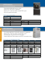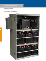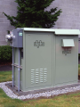
1
> Broadband
Power
Total Power Solutions by ALPHA Technologies
2
Alpha Technologies
>CableUPS®
Alpha Technologies pioneered the concept of reliable uninterruptible power for the broadband cable
television industry, and in the process has set a 30-year precedent for visionary, market-driven power
solutions. Today, Alpha continues to focus on providing the communications industry with the most
reliable, innovative and efficient powering solutions available.
>Intelligence
Alpha works in all areas of communications power, engineering complete systems for specific
applications, technologies and regions: from an Outside Plant Pole Mount enclosure in the
Northeast with wind-driven snow to a Power Node Ground Mount system in the desert heat of
the Southwest. Alpha produces powering systems to operate in specific climates and applications
allowing service operators to better manage assets and resources, and provide greater service
reliability and profitability.
>Sustainability
Energy efficiency is a critical component of a powering communications network. More than that, it
makes economic sense. Alpha’s next generation HP (High Performance) powering systems enable
service operators to focus on energy efficiency while assuring unprecedented reliability, extended
battery runtimes and increased flexibility.
>Collaboration
Working with customers to be more competitive and environmentally-conscious makes us successful,
and hundreds of dedicated Alpha engineers, technicians, craftspeople and field specialists share this
focus. These highly motivated people create proactive solutions that help shape the future of the
industry and Alpha itself – a company where people and power come together.
>The Alpha Group
The Alpha Group represents an alliance of independent companies sharing a common philosophy – to
create world-class powering solutions. Collectively, Alpha Group members develop and manufacture
AC and DC power conversion, protection and standby products. Applications for these products
include broadband cable, telecom, commercial, industrial and renewable energy for a worldwide
customer base. In addition, our companies provide a range of installation and maintenance services.
Members of The Alpha Group include Alpha Technologies, Alpha Energy, Alpha Industrial Power,
Argus Technologies and G.B. Enterprises.
2
Table of Contents
>Alpha Technologies Services
5-9
>Generators
39-43
Depot Repair..........................................................6
AlphaGen™ Curbside............................................40
Alpha Technologies Services Map.........................7
Portable AC and DC Generators.......................... 41
Field Services.........................................................8
AlphaGen™ Portable Trailer..................................42
Turnkey Installation Services..................................9
>Batteries and Accesories
>Cable Power Supplies
45-49
11-17
AlphaCell™............................................................46
XM2-HP................................................................ 12
AlphaCell™ Runtime.............................................. 47
XM2...................................................................... 13
AlphaGuard™........................................................48
GMX...................................................................... 14
Battery Testing Equipment...................................49
XM2-300HP......................................................... 15
APX....................................................................... 16
APP....................................................................... 17
>Fiber Power
51-53
FlexPoint™ 1230 Series.........................................52
Integrated Fiber Enclosure...................................53
>Status Monitoring
19-25
AlphaNet DSM3.................................................20
™
3
AlphaNet™ IDH3.................................................... 21
AlphaNet™ EDH-A2..............................................22
AlphaNet™ EDH4..................................................23
>Enclosure Systems
27-37
LPE Enclosure......................................................28
NPS Enclosure.....................................................28
PWE Enclosure.....................................................29
UPE and UPE-M Enclosures................................30
Extended Runtime Enclosures............................. 31
Powernode Systems............................................32
Enclosure Accessories.........................................34
Surge Protection...................................................36
Precast Pads........................................................37
Pedestal Support Series......................................37
Table of Contents
Continuity Software.............................................. 24
4
Alpha Technologies Services
Alpha Technologies Services
>Alpha Depot Repair Services
Alpha’s repair depots are located across the country offering convenient pick-up and drop off service.
Our repair and development laboratories are designed for product repair and refurbishment, product
improvement, research and modification, to assist with your specific needs.
>Field Service Calls
Trained Alpha field service engineers are dispatched 24 hours per day, 7 days per week in specially
equipped and stocked Alpha service vehicles to perform routine system maintenance or emergency
repair service.
>Preventive Maintenance
An on-going preventive maintenance program helps ensure optimum system reliability and equipment
life. Alpha’s service plan options include performing routine scheduled maintenance, testing of local
and remote alarm operation, and analyzing local data for special requirements. Local service logs are
updated and information is uploaded to our central database.
>Turnkey Installation
Our complete power system integration and turnkey installation services include right-of-way
and easement procurement, site preparation, equipment installation, utility hookup coordination,
system turn-up and system testing.
>Turn-Up and Test Services
5
Turn-up and test services for Headend, DC Plant and Outside Plant installations represent a significant
completion of Alpha start-up procedures and system testing.
>Construction Services
With a national network of contractors and project managers, Alpha Technologies Services can
provide turnkey solutions for outside plant, headend, telecommunications, industrial and renewable
energy applications.
Alpha Technologies Services
first step in ensuring long-term system reliability. Our services include verification of proper installation,
Depot Repair
Extending the life of your power network
>Complete repair and refurbishment of all Alpha
product lines
>Repair of all major brand equipment for cable
headend, fiber optics, line gear, power supplies
and test equipment
>Exclusive two and three year warranties available on
refurbished Alpha and Lectro power supplies
>Warranty and non-warranty repair
Alpha Technologies Services
6
Cable/Telecommunications Equipment Repair Program
Line Equipment
Pick-up services customized to customer’s needs
Quality assurance testing on all equipment
Full distortion testing on all line equipment
Full FCC testing on all headend equipment
Emergency and rush services available
Personalized service from your sales professional
Advance replacement capabilities
Pick up and delivery service
Non-AGC active module
Single-pilot AGC module
Dual-pilot AGC module
Feedforward module
Multifunction network amplifier
Amplifier
Amplifier w/AGC
Motherboard assembly
Housing: repair and/or clean
Fiber optic node receiver/transmitter
Optional Services
Test Equipment
Hybrid and component sales
Field intensity surveys
Pilot frequency changes
Line equipment upgrades
Line equipment modifications
Modulator/processor frequency offsets and/or channel changes
Modulator video color compliance upgrades
Videocipher repairs and upgrades
Test equipment repair and calibration
Headend testing documentation
Prototype testing and evaluation
Computer and monitor repair
On-site calibrations
Technical support
Customized management reports:
• Repair costs each month
• Year-to-date for each system
• Repair cost per module
Line equipment testing documentation
Cable TV analyzers
Signal level meters
Cable leakage meters
Cable locators
Time domain reflectometers (TDRs) and OTDRs
On-site calibration certification
Headend Equipment
Modulator/processor
Modulator/demodulator/processor assembly
Continum/prizma
Signal level meter
SAT receivers
DigiCipher
Sound IF module output LO module, etc.
Fiber optic headend transmitter/receiver
Power Supplies
Standby power supply
Inverter card assembly
AC power supply
Argus rectifiers
Status monitoring
• Transponders
• EDSM
• APM/USM
Power Supplies
Line Gear
Fiber Optic
Headend
Test Equipment
Alpha Technologies Services Map
>Alpha’s Repair Depots are located across the country
>State of the art repair and development laboratories are designed for product
repair and refurbishment, product upgrades, research and modification
>Customizable to assist with your specific needs
>On-site calibration and repair of test equipment
>Alpha certified technicians
Alpha Technologies Services Depot Locations
7
Alpha Technologies Services
3767 Alpha Way
Bellingham, WA 98225
United States
Phone: 360 756 4904
Fax: 360 647 0498
2329 W. Mescal St. #306
Phoenix, AZ 85029
United States
Phone: 602 710 1382
10393 Brockwood Road
Dallas, TX 75238
United States
Phone: 214 217 6300
Fax: 214 217 6313
Toll Free: 877 623 5227
1075 Satellite Blvd. NW
Suite 400
Suwanee, GA 30024
United States
Phone: 678 475 3995
Fax: 678 584 1322
6170 Woodside Executive Ct
Aiken, SC 29803
United States
Phone: 803 643 3790
Fax: 803 643 3798
5055 Central Highway
Pennsauken, NJ 08109
United States
Phone: 856 317 9410
Fax: 856 317 9411
Toll Free: 800 681 8324
Field Services
Extending the life of your power network
>Preventive maintenance
>Plant hardening
>Network power management
>Construction services
>Turnkey installation
>Turn-up and test services
Trained Alpha Field Service technicians and engineers are dispatched 24 hours per day, 7 days per week to perform routine system
maintenance or emergency repair service. In addition, Alpha Technologies Services can combine small-, medium- and large-scale
network hardware upgrades with the necessary installation manpower.
Alpha Technologies Services
8
Preventive Maintenance
Plant Hardening
An on-going preventive maintenance program helps ensure optimum system
reliability and equipment life. Alpha’s service plan options include performing
routine scheduled maintenance, testing of local and remote alarm operation,
and analyzing local data for special requirements. Local service logs are
updated and information is uploaded to Alpha’s central database.
With the necessary manpower and logistics to extend the life of your power
networks, Alpha Technologies Services offers multiple plant hardening options:
• Develop historical data file for each power system component
• Complete preventive maintenance checklists
- Confirm UPS is properly installed with appropriate breaker
- Clean or replace air filters
- Check and repair all battery connections as required
- Test individual cells for voltage and impedance
- Clean, inspect and test as necessary the operation of inverters,
transformers, switches and other components
- Perform a thermal scan using IR thermographs to check final
condition of the UPS and associated circuitry
- Prepare a report on UPS condition with recommendations as necessary
• Perform mechanical maintenance
• Check accuracy of monitoring system readouts and alarm set points
• Document routine service or callouts
Battery Expansion Cabinet installation for longer runtimes to support quad play
applications and critical enterprise equipment
Generator Expansion Module for rapid generator deployment and prolonged
power outages
Top mount battery
expansion cabinet for
UPE-3/6 enclosures
Generator expansion
module for UPE and
PWE enclosures
Under mount battery
expansion cabinet for
PWE-3/6 enclosures
Turnkey Installation
Construction Services
Alpha’s complete power system integration and turnkey installation services
include right-of-way and easement procurement, site preparation, equipment
installation, utility hookup coordination, system turn-up and system testing.
With a national network of contractors and project managers, Alpha
Technologies Services can provide turnkey solutions for outside plant,
headend, telecommunications, industrial and renewable energy applications.
• Performs all site negotiations
• Coordinate utilities and construction permitting process
• Correct installation and maintenance of Headend, DC Plant and Outside
Plant power solutions
• Customers benefit from Alpha’s professional project management and
quality control
Turn-Up and Test Services
Turn-up and test services for Headend, DC Plant and Outside Plant installations
performed by Alpha specialists represent a significant first step in ensuring
long-term system reliability. Services include verification of proper installation,
completion of Alpha start-up procedures and system testing.
• Turn-up and test completed by Alpha technicians
• Certified installation inspections
• Coordinated product and service ordering, tracking and billing
• Extended warranty availability
Complete renewable energy system installations
including design, engineering and construction
Alpha building systems
from concept to
site activation
Turnkey Installation Services
Off-grid, grid-tied solar power
>Complete system engineering, installation
and system commissioning
>Service and support before, during
and after system commissioning
>Liaison with utility companies and local
municipalities throughout the project
16.8kW Alpha Elevated Racking Structure
Elevated Racking Structure in Bordentown, NJ
Largest continuous elevated racking structure in the United States
This 1MW DC grid-paralleled Solar System in Bordentown, NJ is the largest
continuous elevated racking structure in the United States. The system will
provide clean and low-cost power for onsite business operations for the next
20 to 25 years. As part of the Renewable Energy Portfolio available only in New
Jersey, our customer was able to lower the system cost through the sale of
environmental attributes (Solar Renewable Energy Credits).
Off-grid Solar System in Hinsdale, CO
Remote electrical system in Southwestern Colorado
This remote electrical system was built and installed in Southwestern Colorado
as part of a project to improve emergency communications. The site is located at
9700 feet elevation up a narrow and steep ATV path. An 800mHz repeater radio
is the primary load on-site with additional DC and AC power provided for local
emergency fire, rescue and police communication.
The combined load of all the communications systems is just over 50 kilowatt
hours per day – roughly equivalent to the electrical demands of two average gridconnected homes. Not surprisingly, the mandate for this electrical system was
"extreme reliability" so two sources of power generation are available. A 13.86kW
PV array is the primary source of energy, backed up by a 20kW
diesel generator.
The solar power system on this site is intended to meet 86% of the power
requirements, with the remainder of the power coming from the 20kW diesel
generator. The 240Vac output of the generator is converted into 48Vdc by a bank
of Argus Cordex™ 3.6kW rectifiers. The hybrid nature of this system – PV assisted
by a generator – maximizes battery life and minimizes the risk of load loss.
Grid-tied Solar System in Phoenix, AZ
153kW grid-tied solar power system
As part of a broader effort to reduce their power demand and energy expenses,
Cox Communications contacted Alpha Energy to design and implement a solar
power system at its Phoenix, Ariz. headquarters. Alpha Energy worked with a
regional prefabricated parking structure installer and electrical contractor to engineer
and build a series of turnkey Elevated Racking Structures
The 153kW grid-tied solar power system includes 900 photovoltaic panels spread
across six new racking structures, enough to accommodate 75 parking spaces.
The system will generate more than 240,000 kilowatt hours per year, which is
roughly the amount required to power 16 homes. The resulting CO2 offset of
392,081 lbs (178.2 tons) is equivalent to preventing the emissions from 33 cars.
As an added benefit the racking structures provide parking protection from the
elements. These structures also make the solar modules visible from the street to
help demonstrate Cox Communications' commitment to renewable energy.
9
Alpha Technologies Services
This 1MW grid-tied solar power system includes 5,880 photovoltaic panels
spanning a total area of 140,000 square feet. The panels are tied in to one single
electric utility meter via 10 separate inverters; this ensures that if a single array
needs troubleshooting, 90% of the system would still be producing electricity.
The system will generate more than 1,130,000 kilowatt hours per year, which is
roughly the amount required to power 128 homes. The resulting CO2 offset of
2,030,000 lbs (about 923 tons) is equivalent to eliminating the annual emissions
from 169 cars.
10
Cable Power Supplies
Cable Power Supplies
Alpha has provided specialized uninterruptible power supplies (UPS) for more than 30 years. With
impressive backup power capabilities, integrated generators, dual power grid switching and enhanced
battery thermal management, an Alpha CableUPS® ensures improvement in the overall efficiency and
reliability of a broadband network.
>XM2-HP
Alpha’s XM2-HP CableUPS® is the answer to the higher energy costs associated with running today’s
cable networks. The XM2-HP power supply features a high efficiency transformer with lower power
consumption and lower life cycle costs. This “green” power supply can greatly reduce the carbon
footprint of the entire cable plant by running more efficiently 24/7. Additional features include an
enhanced Smart Display with improved menus and a dedicated Communications menu with
DOCSIS® parameters. The XM2-HP is available in three convenient power ratings for load matching to
operate at optimal efficiency.
>XM2
Alpha’s XM2 CableUPS is the industry’s leading power technology. A variety of power ratings make it
an ideal match for network architectures worldwide. Advanced product design features include
hot-swappable modular inverter and smart display. Optional independent dual outputs and N+1
redundant capability provide additional protection and enhanced system reliability. AC or DC generator
compatibility, flexible system control and advanced status monitoring options support easy migration
to clustered or centralized powering.
11
>GMX
Alpha’s GMX is a cost-effective CableUPS designed for cable operators who need a reliable, basic
smart display, terminal block output connections, 63 and 87V output taps, external battery
temperature probe, built-in chassis handle and removable MOV’s.
>XM2-300HP
The XM2-300HP is the ideal CableUPS powering solution for rapidly expanding cable broadband
networks and services. When used in applications requiring less power than traditional outside plant
powering, service operators will experience increased efficiency and reduced operating costs. This low
power system features a much smaller footprint and is engineered for use in multiple dwelling units
(MDU), business parks and node segmentations, as well as Fiber Deep, N+0 and N+1 plant extensions.
Rated at 300 Watts, with a 12V inverter, this power supply features an XM2 smart display and a
DOCSIS-based status monitoring card.
>APX
Alpha’s APX is designed for communication networks that require compact, non-standby
power supplies. The APX’s ferroresonant design provides fully regulated output voltage, surge
and short-circuit protection. The APX can be easily upgraded by adding modular plug-in options
such as a Lightning Arrestor, Time Delay Relay, Ammeter, Status Indicator LED or AmpClamp™
Surge Suppressor.
>APP
The APP is a portable non-standby power supply used to provide conditioned AC power to
the load when the main power supply is being serviced. Used in conjunction with the "Alternate"
connector and the "ALT/ON" switch located on the enclosure's service power inserter, power can
be transferred from the main power module to the APP without interrupting the connected load.
Cable Power Supplies
uninterruptible power supply. Features of the GMX include an embedded status monitoring card slot,
XM2-HP
CableUPS® Power Supply
>New high efficiency transformer
>New communications menu
>6, 15 and 22A models available
>Next generation microprocessor
>Backwards compatible with XM Series 2 CableUPS
>Integrated and External DOCSIS® Transponders
>Integrated and External Proprietary Transponders
XM2-HP
XM2-HP
Models:
XM2-906HP
XM2-915HP
XM2-922HP
Input Voltage (Vac):
120 / 240
120 / 240
200 / 240
Input Voltage Tolerance:
-30% to +20%
±15%
±15%
Input Frequency:
60Hz
60Hz
60Hz
Frequency Tolerance:
±3%
±3%
±3%
Output Voltage (Vac):
63 / 87
63 / 75 / 87
63 / 75 / 87
Output Current (A):
8/6
22.5 / 18 / 15
22.5
Max Output Power (VA):
525
1350
2025
Electrical
12
Quasi-square wave
Waveform:
±5%
Voltage Regulation:
±0.05% inverter mode, ±1% normal mode
Cable Power Supplies
Output Frequency Stability:
150% of maximum current rating
Short Circuit Current:
93% typical line mode, 87% typical standby mode
Transformer Efficiency:
Uninterrupted output
Transfer Characteristics:
Battery Voltage (Vdc):
36
36
48
Battery Charger
Programmable (0 to 5mV/Cell/°C)
Temperature Compensation:
10A at 80% load and nominal input (bulk charge mode)
Charger Current:
Bulk, accept, float
Three Stage:
Mechanical
Smart Display 2 x 20 LCD with backlight
Status Display:
Dimensions
H x W x D (in/mm):
Approx. Weight (lb/kg):
Finish:
8.8 x 15 x 13 / 222 x 381 x 330
60 / 27
70 / 32
92 / 42
Black, epoxy powdercoat
Environment
Operating Temperature:
Humidity:
Agency Compliance:
Smart Display Features:
-40 to 55°C / -40 to 131°F
0 to 95% non-condensing
FCC Part 15 Class A, UL1778, CSA 22.2 No. 107.1-M95
Output current, Input frequency, Battery voltage, Battery temperature, Output VA, Standby time, DOCSIS® parameters,
Built-in diagnostics, Output power (W), Output voltage, % load, Input voltage, Charger current, Number of events
Note: General Specifications reference most commonly used models. For model-specific information, consult product manual. Other voltages and configurations may be available. For more information,
contact your sales representative.
Optional Features
PIM/N+1 Protective Interface Module: Provides two programmable outputs from a single XM Series 2 power supply. The PIM protects system components and provides
isolation between distribution legs by shutting down the individual load during over-current conditions. The PIM has a user-programmable over-current threshold, as well as a
programmable over-current tolerance period to specify the time in seconds (1 to 10) that an over-current condition is allowed on the XM Series 2 output before the individual
output channel is shut down. A user programmable retry limit allows the user to select how many times (1 to 40) the PIM will attempt to reconnect an output that was shut
down for an over-current condition. The PIM also provides redundant power supply capability (N+1) for multiple power supply configurations.
XM2
CableUPS® Power Supply
>Proven CableUPS® uninterruptible power supply
>Programmable LCD Smart Display
>6, 15 and 22A models available
>Modular design with hot-swappable inverter
XM2
>Programmable, temperature-compensated battery charger
>Integrated and External DOCSIS® Transponders
>Integrated and External Proprietary Transponders
XM2
Models:
XM2-910
XM2-915
XM2-915 HV
XM2-1350-48
XM2-922
XM2-922 HV
Input Voltage (Vac):
120 / 240
120 / 240
120 / 240
120 / 240
200 / 240
200 / 240
Input Voltage Tolerance:
±15%
±15%
-25% to +15%
±15%
±15%
-25% to +15%
Input Frequency:
60Hz
60Hz
60Hz
60Hz
60Hz
60Hz
Frequency Tolerance:
±3%
±3%
±3%
±3%
±3%
±3%
Output Voltage (Vac):
63 / 75 / 87
63 / 75 / 87
63 / 75 / 89
63 / 75 / 87
63 / 75 / 87
63 / 75 / 89
Output Current (A):
10
22.5 / 18 / 15
22.5 / 18 / 15
22.5 / 18 / 15
22.5
22.2
Max Output Power (VA):
900
1350
1350
1350
2025
2025
48
48
Electrical
Quasi-square wave
Waveform:
±5%
Voltage Regulation:
±0.05% inverter mode, ±1% normal mode
Output Frequency Stability:
90% typical line mode, 84% typical standby mode
Transformer Efficiency:
Uninterrupted output
Transfer Characteristics:
36
36
36
48
Battery Charger
Programmable (0 to 5mV/Cell/°C)
Temperature Compensation:
10A at 80% load and nominal input (bulk charge mode)
Charger Current:
Bulk, accept, float
Three Stage:
Mechanical
Smart Display 2 x 20 LCD with backlight
Status Display:
Dimensions
H x W x D (in/mm):
Approx. Weight (lb/kg):
Finish:
8.8 x 15 x 13 / 222 x 381 x 330
62 / 28
70 / 32
64 / 29
70 / 32
92 / 42
92 / 42
Black, epoxy powdercoat
Environment
Operating Temperature:
Humidity:
Agency Compliance:
Smart Display Features:
-40 to 55°C / -40 to 131°F
0 to 95% non-condensing
FCC Part 15 Class A, UL1778, CSA 22.2 No. 107.1-M95
Output current, Input frequency, Battery voltage, Battery temperature, Output VA, Standby time,
Built-in diagnostics, Output power (W), Output voltage, % load, Input voltage, Charger current
Note: General Specifications reference most commonly used models. For model-specific information, consult product manual. Other voltages and configurations may be available. For more information,
contact your sales representative.
Optional Features
PIM/N+1 Protective Interface Module: Provides two programmable outputs from a single XM Series 2 power supply. The PIM protects system components and provides
isolation between distribution legs by shutting down the individual load during over-current conditions. The PIM has a user-programmable over-current threshold, as well as a
programmable over-current tolerance period to specify the time in seconds (1 to 10) that an over-current condition is allowed on the XM Series 2 output before the individual
output channel is shut down. A user programmable retry limit allows the user to select how many times (1 to 40) the PIM will attempt to reconnect an output that was shut
down for an over-current condition. The PIM also provides redundant power supply capability (N+1) for multiple power supply configurations.
Cable Power Supplies
150% of maximum current rating
Short Circuit Current:
Battery Voltage (Vdc):
13
GMX
CableUPS® Power Supply
>Line Interactive Ferro Technology (LIFT)
>Wide input voltage range of ±30%
>Compact packaging with light weight ferro
>Field programmable flash memory
GMX
>Integrated DOCSIS® Embedded Transponder
>Built-in battery circuit breaker
>IEC-style line cord
GMX
Models:
GMX-915
GMX-915P
Electrical
Cable Power Supplies
14
Input Voltage (Vac):
120
240
Input Voltage Tolerance:
±30% @ 115V (80 to 150vrms)
±30% @ 225V (158 to 292vrms)
Line Return:
±25%
±25%
Nominal Input Current1:
13A
7A
Input Frequency:
60Hz
60Hz
Frequency Tolerance:
±3Hz
±3Hz
DC Voltage (Vdc):
36
36
Low DC Voltage Cutout:
1.75V/Cell
1.75V/Cell
Output Voltage (Vac):
63 / 87 (Field selectable)
63 / 87 (Field selectable)
Output Regulation, 87V Tap2:
±3%
±3%
Output Regulation, 63V Tap2:
±4%
±4%
Output Current:
15A
15A
Output Frequency Stability:
60Hz, ±1Hz (Inverter operation)
60Hz, ±1Hz (Inverter operation)
Waveform:
Quasi-square wave
Quasi-square wave
Battery Charger
Charge Current3:
10A
10A
Temperature Compensation:
-5MV/Cell/°C (Programmable)
-5MV/Cell/°C (Programmable)
Constant Current Operation:
High Rate Charge to 90% Capacity
High Rate Charge to 90% Capacity
Constant Voltage Operation:
2.4V/Cell (Typ. 7hrs) @ 25°C / 77°F
2.4V/Cell (Typ. 7hrs) @ 25°C / 77°F
Dimensions
H x W x D (in/mm):
7.8 x 18.3 x 11.4 / 198 x 465 x 290
7.8 x 18.3 x 11.4 / 198 x 465 x 290
Weight (lb/kg):
60 / 27.5
60 / 27.5
Front Panel Display (LCD):
2 x 20 Character LCD
2 x 20 Character LCD
Front Panel Indicators (LED):
Output status and alarm
Output status and alarm
Finish:
Black, epoxy powdercoat
Black, epoxy powdercoat
Operating Temperature:
-40 to 55°C / -40 to 131°F
-40 to 55°C / -40 to 131°F
Humidity:
0 to 95% non-condensing
0 to 95% non-condensing
Elevation:
0 to 3000m / 0 to 10000ft above sea level
0 to 3000m / 0 to 10000ft above sea level
Status Monitoring4:
Optional DSM and ESM
Optional DSM and ESM
Agency Compliance:
UL 1778/CSA C22.2, No. 107.1
UL 1778/CSA C22.2, No. 107.1
Emissions:
CISPR 22, Class A
CISPR 22, Class A
Mechanical
Environment
Communication
Notes:
1
Batteries fully charged 2 Output regulation at nominal input frequency. Frequency variations will proportionally affect the output voltage (i.e., a 1% reduction in frequency will result in approximately a 1%
drop in output voltage) 3 Varies with input line voltage and output load 4 Status monitoring and embedded transponders are optional
XM2-300HP Power Supply
High Efficiency CableUPS®
>High efficiency 300W power supply
>XM2 Programmable LCD Smart Display
>New predictive preventive maintenance features
>Small footprint and lightweight
>Ideal for RFoG, MDU and N+0 applications
>Integrated DOCSIS® status monitoring
XM2-300HP
XM2-300HP
Model:
XM2-300HP
Electrical
120
Input Voltage Tolerance:
-15% to +10%
Input Frequency:
60Hz
Frequency:
±3%
Output Voltage (Vac):
63/87
Output Current (A):
4.8/3.5
Max Output Power (VA):
300
Waveform:
Sine wave
Voltage Regulation:
±5%
Output Frequency Stability:
±0.05% inverter mode, ±1% normal mode
Short Circuit Current:
150% for ten seconds
Transformer Efficiency:
94% typical line mode, 88% typical standby mode
Battery Voltage (Vdc):
12
Battery Charger
Temperature Compensation:
Programmable (0 to 5mV/Cell/°C)
Charger Current:
6A minimum - 10A maximum
Three Stage:
Bulk/Accept/Float
Mechanical
Status Display:
Smart display 2x20 LCD with backlight
Dimensions
H x W x D (in/mm):
8.5 x 9.0 x 8.0 / 216 x 229 x 203
Approx. Weight (lb/kg):
22/10
Finish:
Black, epoxy powdercoat
Environment
Operating Temperature:
-40 to 55°C / -40 to 131°F
Humidity:
0 to 95% non-condensing
Agency Compliance:
FCC Part 15 Class A, UL / CSA 1778
Smart Display Features:
Output current, Input frequency, Battery voltage, Battery temperature, Output VA, Standby time, Built-in diagnostics, Output power (W),
Output voltage, % load, Input voltage, Charger current
Advanced Diagnostics
Advanced Analytics:
User Inputs:
• Onboard battery algorithm for predictive service required
• Onboard inverter algorithm to trend inverter performance
• Power supply install and battery manufacturing dates
• Power Supply priority level
• IP Server address
• Siemens values during battery preventive maintenance cycles
15
Cable Power Supplies
Input Voltage (Vac):
APX
Non-Standby Power Supply
>Complete line conditioning
>Modular transformer design
>Flexible mounting options
>Current limited output and short circuit protection
APX Series
APX Series
Models:
16
Input
Voltage (Vac)
Input
Frequency (Hz)
Output
Voltage (Vac)
Max. Output
Power (VA)
Input Protection
(breaker)
Output
Protection (fuse)
Weight
(lb/kg)
APX 6008:
120
60
63
8
480
8A
10A
21 / 9.5
APX 6014:
120
60
63
14
840
12A
15A
30 / 13.6
APX 9015-120:
120
60
63/75/87
15
1350
12A
20A
47.5 / 21.6
APX 9015-240:
240
60
63/75/87
15
1350
12A
20A
47.5 / 21.6
APX 9015-120 HV:
120
60
63/75/89
15
1350
12A
20A
51 / 23
APX 9015-240 HV:
240
60
63/75/89
15
1350
12A
20A
51 / 23
APX 6008 RM:
120
60
63
8
480
8A
10A
22 / 10
APX 6014 RM:
120
60
63
14
840
12A
15A
31 / 14
Note: Other voltages and configurations may be available. For more information, contact your local Alpha sales representative.
Input
Cable Power Supplies
Output
Current (A)
Mounting Options
Power Factor:
>0.90 at full load
Voltage Tolerance:
±15%
Voltage (APX 9015 HV):
-25 to 15%
Frequency:
±3%
Output
Waveform:
Quasi-square wave
Regulation:
±5%
Efficiency:
90% or better
Pole Mount (PM): Built of durable, weather-resistant, powdercoated aluminum to
withstand the harshest environments. This enclosure also includes brackets that
provide for easy bolted, or banded Pole Mounting.
Wall Mount (WM): Allows the module to be mounted on a flat, vertical surface.
Shelf Mount (SM): Allows the module to be mounted on flat, horizontal
surfaces such as the PWE or UPE enclosures. An extended input power
cable is also included.
Pedestal Mount (PED): Ideal for ground mount applications, and provides
weather-resistant, steel construction. The APX PED is available in either
concrete or soil mount versions (please specify at time of order).
Rack Mount (RM): Ideal for mounting the power supply in a standard 19" rack.
Mechanical
Dimensions H x W x D
APX 6008, 6014 (in/mm):
11.75 x 7.5 x 10.5 / 298 x 190 x 267
APX 9015 (in/mm):
15.5 x 8.5 x 11 / 394 x 216 x 279
Finish:
Durable powdercoat
Enclosure Material:
Aluminum
Environment
Operating Temperature:
-40 to 55°C / -40 to 131°F
Agency Compliance:
UL1012/CSA C22.2 No. 107.1-M95
Optional Features
SIL-C:
Long life LED pilot light
LA-M:
Plug-In lightning arrestor (120V)
AMM-C:
Easy reading panel ammeter
TDR-M:
Time delay relay (10 to 60sec variable)
ACAT-3P:
Plug-In Amp Clamp™
GLK:
Enclosure security lock (PM)
APX - Cover removed
APP
Service Power Supply
>Portable service power supply
>Time proven ferroresonant technology
>Selectable input and output voltages
>15A and 22A versions available
APP9022S
APP
APP9015S
APP9022S
Input Voltage (Vac):
120/240 ±15%
120/240 ±15%
Input Current (A):
12
16/12 max.
Input Frequency:
60Hz
60Hz
Output Voltage (Vac):
60/75/87 ±5%
60/75/87 ±5%
Output Current (A):
15
17 (22 at 240Vac Input)
Output Power (VA)
(Continuous):
1350
1350/1650/2000
Output Current Limit:
150% of output rating
150% of output rating
Efficiency:
90% typical @ rated load
90% typical @ rated load
Agency Compliance:
—
CSA
Finish:
Durable powdercoat
Durable powdercoat
Operating Temperature:
-40 to 50°C / -40 to 122°F
-40 to 50°C / -40 to 122°F
Dimensions
H x W x D (in/mm):
9 x 9.5 x 13.75 / 229 x 241 x 349
9 x 9.5 x 14.75 / 229 x 241 x 375
Weight (lb/kg):
47 / 21
60 / 27
17
Cable Power Supplies
Models:
APP Kits:
APP-9015S Kit Includes:
874-726-20 — Line Cord Assy, 120Vac, 5-20P, APP-9015S
874-727-20 — Line Cord Assy, 240Vac, 6-15P, APP-9015S
874-728-20 — Output Cable Assy, Jones Connector, APP-9015S
874-712-20 — WR KT, ADPTR, SPS JONES to SPI 25XM
APP-9022S Kit Includes:
874-935-20 — Line Cord Assy, 120Vac, 5-20P, APP-9022S
874-935-21 — Line Cord Assy, 240Vac, 6-15P, APP-9022S
All output cables for the APP-9022S are to be ordered as separate line items. One standard output cable kit (745-223-20) is included in the price of the APP-9022S.
Additional output cables or 30ft cable kits can be ordered (additional cost) as needed.
745-223-20 Kit Includes:
874-949-20 — Y-Cables, 25A Connectors, 6', APP-9022S
874-949-21 — Y-Cables, Jones, 6', APP-9022S
875-173-20 — Lectro Adapter, Lectro to APP-9022S
Cables:
874-726-20 (5-20 plug)
Power cord with 5-20P
plug (120Vac)
874-727-20 (6-15 plug)
Power cord with 6-15P
plug (240Vac)
874-728-20
Output cable, single Jones
875-173-20
25A Lectro Adapter
874-935-20 (5-20 plug)
Power cord with 5-50P
plug (120Vac)
874-935-21 (6-15 plug)
Power cord with 6-15P
plug (240Vac)
874-935-22
Optional 10-Ft cord with
30A connector and
Twist Lock Plug (125Vac)
874-949-20
Y cable with
25A connectors
874-949-21
Y cable with
Jones connectors
874-949-32
30-Ft cable
874-949-33
Y cable adapter for
25A connector
874-949-34
Y cable adaptor for
Jones connector
18
Status Monitoring
Status Monitoring
Monitoring, measuring and managing power supplies, batteries and generators are no easy tasks.
However, in order to maintain customer satisfaction, reduce operating costs and meet regulatory
requirements, cable service providers need specific information from their systems. Alpha’s status
monitoring solutions use state-of-the-art communications technology to transmit critical network
performance data to the headend or network management center. This allows cable providers to
be proactive and take corrective action before serious problems occur. Whether you are extending
the life of your network backup power through battery balancing, managing QoS for VoIP services,
or monitoring for trouble areas during an AC power outage, the AlphaNet™ series of products
provides the tools to manage today’s network power requirements with the ability to upgrade for
tomorrow’s needs.
>AlphaNet DSM
Alpha’s AlphaNet family of networking products including the DOCSIS® Status Monitor (DSM)
broadband power communication card enables Alpha’s XM2-HP, XM2, XM2-300HP and GMX
CableUPS® to connect directly to an HFC network through an embedded DOCSIS cable modem.
Through a Simple Network Management Protocol (SNMP) interface, standard MIBs are used for
quick, efficient network status and diagnostics. A WEB interface enables any authorized personnel
direct access to powerful, advanced diagnostics using a common web browser. No proprietary
software is required. A single DSM installed in an Alpha CableUPS supports communications and
system control for multiple Alpha power supplies and an AlphaGen™ generator system.
>AlphaNet Family of Embedded and External Transponders
19
The AlphaNet family of products includes monitoring solutions for any of your broadband cable
network management needs. Let us help you select a solution that fits your requirements.
Continuity-SPS (Standby Power Supply) is a flexible standby power supply status monitoring solution.
Based on HMS and DOCSIS standards, Continuity supports any standards-based transponder,
providing cable operators with a centralized, feature-rich, web-enabled tool to monitor all the standby
power supplies in their network.
Status Monitoring
>Continuity DOCSIS Power Supply Monitoring
AlphaNet™ DSM3
DOCSIS ® Status Monitor
>Embedded network management for Alpha broadband power supplies
>Standard network interface including SNMP, Web access and ANSI/SCTE HMS MIBs
>Battery and power supply advanced diagnostics reduces truck
rolls and overall operating expense of powering network
>Optional VoIP testing features
AlphaNet DSM3
AlphaNet DSM
Specifications
Network Communications
Power Supply Models
Supported:
XM2-HP, XM2-300HP, XM2, GMX
Battery Monitoring:
Up to four strings of 36V or 48V batteries
Power System Management:
Management Protocol:
Up to five power supplies and an AlphaGen
generator are managed from a single DSM3.
Coordinated battery charging, system test and
aggregated alarm reporting are each managed
by the DSM3
Standard ANSI/SCTE HMS MIBs support basic
power supply monitoring. Advanced diagnostics
with battery and power module analytics available
via secure SNMP
Advanced Diagnostics1
Status Monitoring
20
DOCSIS (RF) Port Protocols:
Ethernet Port:
MIBs:
IP, UDP, TCP, DHCP, TFTP, SNMPv1, SNMPv2c, HTTP
Local Mode: HTTP web interface for local
craft diagnosis.
CPE Mode: DOCSIS Cable modem Ethernet
CPE functionality
Power Supply (ANSI/SCTE 38-4)
Other SCTE HMS MIBs as defines by the SCTE
for power supply and generator status monitoring
Alpha proprietary advanced UPS diagnostics
Power Supply Monitored Parameters
Major Alarm:
Aggregate alarm consisting of: test fail, battery
fail, line isolation alarm, output overload, inverter,
over-temperature, N+1 active, fuse fail
Minor Alarm:
Aggregate alarm consisting of:
temperature probe error, AC line loss, N+1 error
Intelligent Power Supply
Interface:
Power supply user interface displays advanced
diagnostics including: DOCSIS modem upstream
and downstream RF levels, IP address assigned by
network DHCP server, MAC address and firmware
levels, individual battery voltages to verify correct
wire harness installation.
Input Voltage:
Reported from power supply V(in) measurement
Output Voltage:
Reported from power supply V(out) measurement
Output Current 1-4:
0-25A standard on port 1. Ports 2-4 require
power supply option.
Battery State of Health:
Power supply internal analytic diagnostics report
when batteries should be serviced. Reported
Status:
Batteries OK,
Battery Thermal Warning – PM Visit
Recommended,
Battery Conductance Warning - PM Visit
Recommended,
Battery Thermal Alarm – Service Required
Battery Conductance Alarm - Service Required
Output Power:
Calculated, reported in AC Watts
UPS Status:
AC Line, Standby, Test in process, Test alarm
Enclosure Door:
Open or Closed
Power supply internal diagnostics report if the
power inverter requires service.
Reported Values: Inverter OK, Replace Inverter.
Individual battery conductance measurements
(Mho’s) from portable meters are using the power
supply or DSM craft interface.
Battery Voltage:
Temperature delta between enclosure ambient
and battery (-) terminal is automatically logged.
Generator Monitored Parameters
Power Inverter State
of Health:
Battery Conductance:
Battery Thermal Variance:
Local Interface:
LED Indicators:
Start / Stop power supply test cycle
Status:
Generator Off, Running, Alarm
Generator Alarm:
Aggregate alarm consisting of: low oil pressure, engine
over-temp, engine over-speed, crank limit, over voltage,
low fuel, water intrusion, pad shear, gas hazard, test fail
Ready/Alarm, Upstream Registration,
Downstream Lock, AlphaBus, RF Level, Link,
CPE Traffic, Battery Harness Correct
Gas Hazard:
OK, Alarm
Water Intrusion:
OK, Alarm
Pad Shear:
OK, Alarm
Enclosure Door:
Closed, Open
Ignition Battery Voltage:
+/- 100mV
Enclosure Temperature:
+/- 2°C
Low Fuel:
OK, Alarm
Remote Test Control:
Start / Stop generator test cycle
I/O Control:
4-pin Molex: Digital Input, Digital Output, 5V, Common
AlphaBus:
RJ-11 offset tab: Multi-power supply and
AlphaGen communications
Battery Monitoring:
8-pin Molex battery string A/B, 8-pin Molex
battery string C/D
Tamper:
NO or NC, software configurable, reads
enclosure door magnetic switch
1
Remote Test Control:
F-connector, female, 75 Ohm, connector angle
accommodates coax bend radius when installed
in some enclosures
RJ-45, Ethernet, multi-mode operation
Hardware
RF Cable Interface:
Battery Temperature:
Individual battery voltage, up to four strings of 3
or 4 batteries (maximum 16 batteries), +/- 100mV
per battery
Reported from power supply battery Remote
Temperature Sensor (RTS)
Advanced diagnostics are available through Alpha Certified network monitoring systems
Cable Modem:
Compliance:
DOCSIS 1.1 and 2.0
Operating Temperature:
-40 to 65°C / -40 to 149°F
Transmit Frequency Range:
5 to 42 Mhz
Storage Temperature:
-40 to 85°C / -40 to 185°F
Receive Center Frequency Range:
91 to 857 Mhz
Humidity:
10 to 90% non-condensing
Output Power Range:
8 to 58 dBmV
Input Signal Range:
-15 dBmV to 15 dBmV
Channel Bandwidth:
6 Mhz
Regulatory Compliance:
FCC Part 15 Class A
EN 50083-2:2006 EMC Requirements for CATV Equipment
EN 62040-2:2006 Uninterruptable Power Supply EMC
Requirements, Category C2
Environment
Surge: IEEE 587, Category B3
RoHS: Directive 2002/95/EC
AlphaNet™ IDH3
DOCSIS ® Status Monitor
>Alpha XM2-HP and XM2 embedded status monitoring
>Standard network interface including SNMP,
Web access and ANSI/SCTE HMS MIBs
>Monitors one or two 36V or 48V battery strings
>Used with EDSM interface card
>Optional VoIP testing features
AlphaNet IDH3
AlphaNet IDH3
Specifications
Power Supply Monitored Parameters
Power Supply Models
Supported:
XM2-HP, XM2
Battery Monitoring:
Up to two strings of 36V or 48V batteries
Monitoring Protocol:
SNMP v1
Devices Monitored:
Management Protocol:
Aggregate Alarm consisting of: test fail, battery
fail, line isolation alarm, output overload, inverter
over temperature, N+1 active, fuse fail
Minor Alarm:
Power Supply, Batteries and Generator
(compatible with ANSI/SCTE 25-3 2002,
formerly HMS 022)
Aggregate Alarm consisting of: temperature
probe error, AC line loss, N+1 error
Input Voltage:
Reported from power supply V(in) measurement
Output Voltage:
Reported from power supply V(out) measurement
Standard ANSI/SCTE HMS MIBs support basic
power supply monitoring.
Output Current 1-4:
0-25A standard on port 1. Ports 2-4 require
power supply option.
Output Power:
Calculated, reported in AC Watts
UPS Status:
AC line, Standby, Test in-process, Test alarm
Enclosure Door:
Open/Closed
Battery Voltage:
Up to 2 battery strings
Individual battery voltages measured reported to
±100mv resolution
Battery Temperature:
Reported from power supply battery Remote
Temperature Sensor (RTS)
Remote Test Control:
Start/Stop XM2 self test cycle
Hardware
RF Cable Interface:
F-connector, female, 75 Ohm
Local Interface:
RJ-12, RS-232, 19.2kb,N,8,1
Requires serial port adapter and
PC with terminal emulation software
(Hyper-Terminal recommended)
LED Indicators:
Transponder Ready/RF Link Established
Transponder/CMTS Communications
Power Supply/Transponder Communication
I/O Signals:
Battery, tamper, and AlphaBus interfaces located
on EDSM interface card
Environment
Operating Temperature:
-40 to 65°C / -40 to 149°F
Storage Temperature:
-40 to 85°C / -40 to 185°F
Humidity:
10 to 90% non-condensing
Regulatory Compliance:
EN50022 Class A and FCC Part 15 Class A
(Installed in power supply enclosure system)
Cable Modem:
Compliance:
DOCSIS 1.1 and 2.0
Transmit Frequency Range:
5 to 42 Mhz
Receive Center Frequency Range:
91 to 857 Mhz
Output Power Range:
8 to 58 dBmV
Input Signal Range:
-15 dBmV to 15 dBmV
Channel Bandwidth:
6 Mhz
Generator Monitored Parameters
Status:
Generator off, Running, Alarm
Generator Alarm:
Aggregate alarm consisting of: low oil pressure,
engine over-temp, engine over-speed, crank limit,
over voltage, low fuel, water intrusion, pad shear,
gas hazard, test fail
Gas Hazard:
OK, Alarm
Water Intrusion:
OK, Alarm
Pad Shear:
OK, Alarm
Enclosure Door:
Open, Alarm
Ignition Battery Voltage:
+/- 100mV
Enclosure Temperature:
+/- 2°C
Low Fuel:
OK, Alarm
Remote Test:
Start and Stop control input
21
Status Monitoring
Major Alarm:
AlphaNet™ EDH-A2
External DOCSIS® Transponder
>Add DOCSIS Status Monitoring capability
to existing power supplies
AlphaNet EDH-A2
>Supports standard networking interfaces including
SNMP, Web access and ANSI/SCTE MIBs
>Multiple power supply models supported
>Embedded Web server for remote diagnostics
AlphaNet EDH-A2
Specifications
XP-EDH-A2
Hardware
Power Supplies Supported:
XM2-HP, XM2 (requires USM2 or USM2.5 card)
XM (requires APM/USM), AM (requires RPM card)
Lectro ZTT, ZTT+ and CPR
Dimensions
H x W x D (in/mm):
1.3 x 8.6 x 5.2 / 33 x 218 x 132
RF Cable Interface:
F-connector, female, 75Ohm
DOCSIS Compatibility:
DOCSIS 1.1, 2.0
Monitoring Protocol:
SNMPv1
Local/Craft Interface:
USB
Devices Monitored:
Power supply, batteries
1
Environment
Notes: 1 Reported as per ANSI/SCTE 25-3 2002 (HMS-022)
Status Monitoring
22
RF Transmit/Receive
Tx Frequency Range:
5 to 42MHz
Output Power:
8 to 55dBmV
Channel Bandwidth:
6MHz
Receive Center
Freq Range:
91 to 857MHz (Standard, HRC, IRC channels)
Input Level:
-15 to 15dBmV
Operating Temperature:
-40 to 65°C / -40 to 149°F
Humidity:
10 to 90% non-condensing
Emissions:
EN55022 Class A and FCC Part 15 Class A
(Installed in power supply enclosure system)
Immunity:
Surge Test per Specification (IEEE C62.41-1991)
ESD Protection: ±8kV air discharge, ±6kV
contact discharge as per (IEC 61000-4-2)
Management
Monitored Parameters
NMS/EMS:
Standard SNMP Management Tools
HMS MIBs:
In addition to the standard DOCSIS MIBs, the
transponder supports the following HMS MIBs:
• SCTE 25-3 (HMS-022): - Interface
• SCTE 36 (HMS-050): - Root
• MIB SCTE 37 (HMS-072): - Tree
• MIB SCTE 38-1 (HMS-026): - Property
• MIB SCTE 38-2 (HMS-023): - Alarm MIB
• SCTE 38-3 (HMS-024): - Common
• MIB SCTE 38-4 (HMS-027): - Power Supply
• MIB SCTE 38-7 (HMS-050): - TIB MIB
Power Supply Data
Model:
XM2-HP/
XM2
XM
AM
ZTT
Series
CPR
Major Alarm:
Minor Alarm:
Input Line Voltage Present:
1
1
1
Output Voltage:
1
Battery Voltage:
Output Current:
1
Standby/AC Line Fail:
-
Equipment/Test Fail:
Enclosure Door Status:
Remote Test Control:
Notes: 1 Requires optional cable assembly
Number of Battery Strings:
Up to two 36V or 48V strings
Battery Data:
Individual battery voltages
Battery compartment temperature
-
AlphaNet™ EDH4
External DOCSIS ® Transponder
>Add DOCSIS Status Monitoring capability
to existing power supplies
AlphaNet EDH4
>Supports standard networking interfaces including
SNMP, Web access and ANSI/SCTE MIBs
>Multiple power supply models supported
>Embedded Web server for remote diagnostics
>Optional VoIP testing features
AlphaNet EDH4
Hardware
Specifications
Power Supplies Supported:
XM2-HP, XM2 (requires USM2 or USM2.5)
XM (requires APM/USM)
Lectro ZTT, ZTT+ AM (requires RPM card)
Dimensions
H x W x D (in/mm):
1.3 x 8.6 x 5.2 / 33 x 218 x 132
RF Cable Interface:
F-connector, female, 75Ohm impedance
DOCSIS Compatibility:
DOCSIS 1.1, 2.0
Local/Craft Interface:
RJ45 Ethernet
Monitoring Protocol:
SNMP v1, v2, v3
Environment
Devices Monitored:
Power supplies, batteries, generators1
Operating Temperature:
-40 to 65°C / -40 to 149°F
Humidity:
10 to 90% non-condensing
Emissions:
EN55022 Class A and FCC Part 15 Class A
(Installed in power supply enclosure system)
2 years
Notes: Reported as per ANSI/SCTE 25-3 2002 (HMS-022)
1
RF Transmit/Receive
5 to 42MHz
Output Power:
8 to 58dBmV
Warranty:
Channel Bandwidth:
6MHz
Management
Receive Center
Freq Range:
91 to 857MHz (Standard, HRC, IRC channels)
Input Level:
-15 to 15dBmV
NMS/EMS:
Standard SNMP Management Tools
HMS MIBs:
In addition to the standard DOCSIS MIBs, the
transponder supports the following HMS MIBs:
• SCTE 25-3 (HMS-022): - Interface
• SCTE 36 (HMS-050): - Root
• MIB SCTE 37 (HMS-072): - Tree
• MIB SCTE 38-1 (HMS-026): - Property
• MIB SCTE 38-2 (HMS-023): - Alarm MIB
• SCTE 38-3 (HMS-024): - Common
• MIB SCTE 38-4 (HMS-027): - Power Supply
• MIB SCTE 38-6 (HMS-033): - Generator
• MIB SCTE 38-7 (HMS-050): - TIB MIB
Monitored Parameters
Power Supply Data
Model:
XM2-HP /
XM2
XM
AM
ZTT
Series
Major Alarm:
Minor Alarm:
Input Line Voltage:
1
1
1
Output Voltage:
1
Battery Voltage:
Output Current:
1
Standby/AC Line Fail:
-
Equipment/Test Fail:
Enclosure Door Status:
Remote Test Control:
Notes: 1 Requires optional cable assembly
Number of Battery Strings:
Up to four 36V or 48V strings
Battery Data:
Individual battery voltages
Battery compartment temperature
23
Status Monitoring
Tx Frequency Range:
Continuity Software
DOCSIS ® Power Supply Monitoring
>Enterprise-class, web-enabled and standard-based
>Centralized transponder provisioning and inventory
>Scheduled standby tests for preventive maintenance
>Standby event dashboards
> Enterprise-class Software
> Scheduled Standby Tests Allow for Preventive Maintenance
Web-enabled and standard-based Continuity-SPS (Standby
Continuity-SPS allows you to proactively schedule standby
Power Supply) is a flexible, standby power supply status
tests, which will alarm on risk areas on the network. A
monitoring solution. Based on HMS and DOCSIS standards,
dashboard graphically updates individual battery voltages
Continuity-SPS supports any standards-based transponder,
from standby tests every minute, making it easy to identify
providing cable operators with an enterprise-class,
questionable batteries. These batteries can be replaced
centralized, feature-rich, web-enabled tool to monitor all the
during scheduled maintenance visits before they turn the
standby power supplies in their network.
next standby event into an outage.
24
Status Monitoring
> Centralized Transponder Provisioning and Inventory
> Standby Event Dashboard
With Continuity-SPS you can automatically discover and
Continuity-SPS shows all current, standby events in an
provision all of your transponders from one central location.
easy-to-read dashboard. For each event, the standby event
Continuity-SPS also includes an up-to-date inventory of all
dashboard displays summaries of past standby events and
your transponders that can be exported into Excel or CSV.
shows real-time battery voltages. The standby event
dashboard provides a powerful view into the network
during a power outage.
Continuity Software
DOCSIS ® Power Supply Monitoring
>Powerful visualization and reporting
>Integration with other systems
>Easy to deploy
>Flexible Alarm notification
> Alarm Notification
> Powerful Visualization and Reporting
Continuity-SPS generates alarms for a configurable set of
Continuity-SPS shows power supplies in multiple views: as
warnings and/or alerts according to rules defined by the
a tree structure that represents your network layout; grouped
operator. Real-time alert notification and acknowledgement
by status (such as “Alert” or “Offline”); and on a map (using
helps the operator to reduce downtime due to power failures
address or latitude and longitude to determine the location).
by facilitating a rapid and accurate response to problems.
Power Supplies are always color-coded based on their
Alert notification can be configured to contact scheduled
status (“Warning” or “Standby”), helping the user navigate
support staff via email and/or text message when an alert
Continuity-SPS easily and draw conclusions quickly (such as
condition arises.
identifying a widespread outage by observing a cluster of
offline power supplies on the map).
> Integrating with Other Systems
25
> Easy to Deploy
Cable operators can access Continuity-SPS from any web
Systems when an alarm is created, acknowledged, and
browser. The application is delivered as an appliance that
closed. For example, critical alarms can be forwarded to the
includes server, database and Continuity-SPS software for
NMS at a centralized Network Operations Center.
installation in their own data center.
Status Monitoring
Continuity-SPS can send traps to other Network Monitoring
26
Enclosure Systems
Enclosure Systems
Regardless of the location of a powering system, a solid enclosure is an essential part of the plan.
With one of Alpha’s agency certified enclosures, your power systems are protected from changes
in the climate or weather.
>LPE Enclosure
The LPE is an ideal solution for cable network power where traditional equipment is too large or bulky.
Designed for multiple dwelling units, the LPE is more than 40 percent smaller than a standard PWE
enclosure. Engineered to work with the XM2-300HP power supply and a single 220 GXL or two 70
HPL-FT batteries, the LPE enclosure offers a low-profile solution to keep your customer’s
communications alive.
>NPS Enclosure
The NPS enclosure is for use in business parks, node segmentation and plant extension applications. It is
specifically designed for indoor and outdoor installations requiring lower power, a smaller footprint and
embedded DOCSIS® or proprietary status monitoring capability. The NPS can be conveniently mounted in
an equipment rack, on a wall, on a pole or even on a floor or pedestal using the appropriate installation kit.
>Pole Mount Enclosures
Alpha’s Pole Mount enclosures are the most durable broadband power supply enclosures in the industry.
Each enclosure comes with a removable door and easy opening lid. Standard features include high
magnetic circuit breaker, duplex AC receptacle and service power inserter. Optional features include
battery integration tray, surge protector, battery heater mat, storm hood and battery expansion cabinets.
>Ground Mount Enclosures
>Extended Runtime Add-on Enclosures
Alpha’s battery expansion cabinets have the same rugged construction as the rest of the enclosure
line. These cabinets allow a retrofit battery upgrade to increase runtime on VoIP networks. Available
options include top and bottom mount cabinets for most standard Alpha enclosures, as well as stand
alone options to work with any Broadband enclosure.
>Powernode Systems
Alpha’s Powernode (PN) Series enclosures offer flexibility and modular expandability for broadband
powering applications. Supporting centralized or distributed powering architectures, PN Series enclosures
accommodate multiple power supplies, battery strings and natural gas or propane generators.
>Enclosure Accessories
Extend battery runtime and protect your power system investment with enclosure accessories. Security
add-ons help prevent the theft of valuable equipment, while accessories like Battery Heaters Mats and
Battery Spacers help get the best performance from your batteries in any climate or condition.
>Surge Protection
Alpha’s surge protection devices provide reliable protection of power supplies and related equipment
from the damaging powerline disturbances common to cable and broadband applications.
>Precast Pads for Enclosures
Alpha offers a line of precast, polymer concrete pads for most Alpha Enclosures including AlphaGen™
generator systems. All precast pads include 3/8" mounting hardware to ease field installation.
>Pedestal Support Series
Alpha provides two pedestal support systems for the UPE Series ground mount enclosures. The PS-6
supports UPE Series 3 and 4 battery enclosures and the PS-6XL, with a larger battery vault, supports
3, 4, 6 and 8 battery enclosures.
27
Enclosure Systems
Alpha’s Ground Mount enclosures can be seen installed all over the world. Each enclosure comes with a
removable door and easy opening lid. Standard features include high magnetic circuit breaker, duplex AC
receptacle and service power inserter. Optional features include battery integration tray, surge protector,
battery heater mat, storm hood, battery expansion cabinets and meter enclosure models.
LPE Enclosure
Indoor/Outdoor Enclosure
>Economical and lightweight enclosure solution
>Ideal for RFoG, MDU and N+0 applications
>More than 40% smaller than Alpha’s standard PWE-3 system
>Pole, wall or ground mount options
LPE Enclosure (For use with XM2-300HP)
LPE Enclosure
Mechanical
Dimensions
H x W x D (in/mm):
26 x 16.4 x 11.25 / 660 x 417 x 286
Weight (lb/kg):
25 / 11.3
Specifications
28
Material:
Exterior powdercoated aluminum
Battery:
220 GXL or two 70 HPL-FTs
Door and Lid Seal:
Poron gasketing
Tamper Switch:
Optional
Color:
Gray (custom colors available)
Groundmount Pedastal:
Optional
Lid:
Removable
Service Power Inserter:
Optional SPI or SPI-RF
Door:
Hinged removable
NPS Enclosure
Enclosure Systems
Indoor/Outdoor Enclosure
>For low power applications including fiber deep up to N+6 applications
>More than 22% smaller than Alpha’s standard PWE-3 system
>Convenient pole, wall, ground and rack mount options
>Optional AlphaGuard™ battery balancer and SPI-RF service power inserter
NPS Enclosure
NPS Enclosure (For use with XM2-906HP and XM2-300HP)
Models:
NPS-R
NPS-W1
NPS-W2
NPS-F
NPS-P
Installation:
Indoor
Indoor
Outdoor
Indoor
Outdoor
Description:
19" and 23" Rack mount
Wall mount
Wall mount
Floor mount
Pole mount
Dimensions
H x W x D (in/mm):
22.75 x 19 x 14.14 /
578 x 432 x 359
22.75 x 17 x 14.14 /
578 x 432 x 359
22.75 x 17 x 14.14 /
578 x 432 x 359
22.75 x 17 x 14.14 /
578 x 432 x 359
22.75 x 17 x 14.14 /
578 x 432 x 359
Weight (lb/kg):
39 / 17.7
39 / 17.7
39 / 17.7
39 / 17.7
39 / 17.7
Configurations
Mechanical
Node Power
Supply Enclosure
Configurations:
With GXL Batteries
With 115 HPL Batteries
Specifications
Material:
Exterior powdercoated aluminum
Door:
Hinged removable
Door and Lid Seal:
Poron gasketing
Tamper Switch:
Optional
Color:
Gray (custom colors available)
Battery Side Tray:
Optional
Lid:
Removable
PWE Enclosure
Outdoor Pole Mount Enclosure
>Engineered for broadband powering applications
>Aluminum welded construction and durable powdercoated exterior
>Agency certified to meet applicable industry standards
>Internal or external SUSE rated service entrance options
>Optional Battery Integration Tray (BIT)
PWE-3
>Portable generator cabling access door
>Optional Northern Enclosure available for colder climates
PWE Enclosures
PWE-3
PWE-3
Northern Enclosure
PWE-4
PWE-6
PWE-6
Northern Enclosure
Dimensions
H x W x D (in/mm):
24.5 x 24.3 x 14 /
622 x 615 x 355
25.4 x 24.8 x 14.1 /
645 x 628 x 359
24.8 x 30.3 x 16 /
629 x 768 x 406
36.8 x 24.3 x 14 /
933 x 615 x 355
37.7 x 24.8 x 14.1 /
958 x 628 x 359
Weight (lb/kg):
39 / 18
(without batteries)
42 / 19.1
(without batteries)
57 / 26
(without batteries)
68 / 31
(without batteries)
73 / 33.1
(without batteries)
PWE-6FT
PWE-8
PWE-9
PWE-D36
Dimensions
H x W x D (in/mm):
27.5 x 29.3 x 17.5 /
698 x 753 x 445
36.9 x 30.3 x 16 /
937 x 768 x 406
47 x 24.3 x 14 /
1194 x 615 x 355
47 x 24.3 x 14 /
1194 x 615 x 355
Weight (lb/kg):
57 / 26
(without batteries)
121 / 55
(without batteries)
85 / 38.5
(without batteries)
75 / 34
(without batteries)
Models:
Mechanical
PWE Enclosures (cont.)
Models:
Mechanical
PWE Enclosure
Configuraions
Specifications
Northern Enclosure Hood and Door for Colder Climates
Material:
Exterior powdercoated aluminum
Door and Lid Seal:
Poron gasketing
Color:
Gray (custom colors available)
Lid:
Removable
Door:
Hinged removable
Pole Mount:
Galvanized steel brackets for wood, and concrete
pole mount and wall mount
Tamper Switch:
Optional
Battery Side Tray:
Optional
Northern Enclosures feature Z-bracket, vented hood and doors with
no batting required.
Enclosure Systems
PWE Enclosure
Configuraions
29
UPE and UPE-M Enclosures
Outdoor Ground Mount Enclosures
>Engineered to accommodate broadband powering applications
>Internal or external SUSE rated service entrance options available
>Enclosures are CSA/UL certified to meet applicable industry standards
>Aluminum welded construction and durable powdercoated exterior
>Portable generator cabling access door
>Multiple enclosure accessories and options available
UPE-6
UPE - Ground Mount Enclosures
Models:
UPE-3
UPE-4
UPE-6
UPE-6L
UPE-8
Dimensions
H x W x D (in/mm):
33.5 x 26 x 15 /
851 x 660 x 381
35 x 34.5 x 15 /
889 x 876 x 381
48 x 26 x 15 /
1219 x 660 x 381
36 x 26 x 15 /
914 x 882 x 381
45.5 x 34.5 x 15 /
1136 x 882 x 381
Weight (lb/kg):
61 / 28
(without batteries)
72 / 32
(without batteries)
75 / 34
(without batteries)
68 / 30
(without batteries)
121 / 55
(without batteries)
Mechanical
30
Enclosure Systems
UPE Configurations:
UPE - Metered Ground Mount Enclosures
Models:
UPE-M3
UPE-M6
UPE-M8
Dimensions H x W x D (in/mm):
45 x 26 x 19.7 / 1143 x 660 x 482
57.3 x 26 x 19.7 / 1455 x 660 x 482
50 x 32 x 20.5 / 1270 x 813 x 521
Weight (lb/kg):
100 / 44 (without batteries)
130 / 59 (without batteries)
140 / 64 (without batteries)
Mechanical
UPE-M Configurations:
Specifications
Material:
Exterior powdercoated aluminum
Door and Lid Seal:
Poron gasketing
Color:
Gray (custom colors available)
Lid:
Removable
Door:
Removable/Lockable
Ground Mount:
Precast polymer concrete pad (optional)
Tamper Switch:
Optional
Battery Side Tray:
Optional
Extended Runtime Enclosures
>Upgrade existing Alpha enclosures
>Extend existing runtimes by up to 300%
>Plant hardening option for voice and data broadband networks
BE-PWE mounted on PWE-3
BE-PWE
Adds battery capacity to the PWE-3 Enclosure
Installs onto top of PWE-3
Kit Includes enclosure with sliding battery tray,
door, battery cabling and pole mount bracket
Compatible with AlphaCell™ 165, 195 and
220 Batteries
LBE-3
Adds battery capacity to Lectro 3 battery pole
mount enclosure
Installs onto bottom of Lectro Enclosure
Kit Includes enclosure with sliding battery tray,
door, battery cabling, and pole mount bracket
Compatible with AlphaCell 165, 195 and
220 Batteries
31
UBE-PWE
BE-UPE
Adds battery capacity to the UPE-3 Enclosure
Kit Includes enclosure, and battery cabling
Compatible with AlphaCell 165, 195 and
220 Batteries
PWE-SG
Adds battery capacity to any OEM pole
mount enclosure
Installs underneath of existing pole
mount enclosure
Kit includes conduit kit, battery cabling and
pole mount bracket
Accommodates 3 or 4 AlphaCell 165, 195
or 220 Batteries
Thermally stable underground environment helps
promote maximum battery life and performance
Reduces visual impact with below-grade
battery installation
Durable, maintenance-free, long-lasting, utility
approved and non-combustible material
Large battery capacity houses up to eight
batteries for extended backup time
Flexible enclosure options for both pole and
ground mount systems
PWE Generator Expansion Module
Provides an easy means to pole mount the
AlphaGen™ EU2000
Protects generator from inclement weather
Prevents theft of valuable portable generators
Field installable using two rails attached to the
bottom of the PWE
Backwards compatible with existing enclosure
Accommodates Line Transfer Switch (LTS)
Can be easily removed after extended outage
or left in place
Designed to provide four to ten hours of
additional runtime
Universal Generator Expansion Module
Add an AlphaGen EU2000 to an Alpha PWE
or UPE Enclosure
Protects generator from inclement weather
Prevents theft of valuable portable generators
Backwards compatible with existing enclosure
Accommodates Line Transfer Switch (LTS)
Can be easily removed after extended outage
or left in place
Designed to provide four to ten hours of
additional runtime
Enclosure Options
Adds battery capacity to the PWE-3 Enclosure
Installs onto bottom of PWE-3
Kit Includes enclosure with sliding battery tray,
door, battery cabling and pole mount bracket
Compatible with AlphaCell 165, 195 and
220 Batteries
Underground Battery Vaults
Powernode Systems
Extended Runtime Powering
>Supports centralized or distributed powering architectures
>Compatible with AlphaGen™ generator systems or
multiple battery strings for extended runtime solutions
PN-3 with AlphaGen
CESC
Specifications
CESC
Dimensions
H x W x D (in/mm):
44 x 15 x 24 /
1118 x 381 x 610
Weight (lb/kg):
51 / 23.13
Power Supply Capacity:
One power supply
Color:
Seafoam Green,
optional colors available
Standard Features:
Removable/Lockable doors
Finish:
Durable powdercoat exterior
Material:
Aluminum
Sidecar
1 Power Supply,
1 Battery String
32
PN-3
Enclosure Systems
Specifications
Dimensions
H x W x D (in/mm):
44 x 26 x 24 /
1118 x 660 x 610
Weight (lb/kg):
115 / 52 (without trays)
Power Supply Capacity:
Up to two power supplies
Color:
Seafoam Green,
optional colors available
Standard Features:
Removable/Lockable doors
Finish:
Durable powdercoat exterior
Material:
Aluminum
Single PN-3
Dual PN-3
PN-3/CE-3X2
1 Power Supply
2 Battery Strings
2 Power Supplies
4 Battery Strings
2 Power Supplies
1 Battery String
AlphaGen™ Generator
The PN-3 enclosure can accommodate a maximum combination of three equipment or battery trays.
PN-3-HS (High Security)
Specifications
Dimensions
H x W x D (in/mm):
44 x 26 x 24 /
1118 x 660 x 610
Weight (lb/kg):
115 / 52 (without trays)
Power Supply Capacity:
Up to two power supplies
Color:
Seafoam Green,
optional colors available
Standard Features:
Removable/Lockable doors
Finish:
Durable powdercoat exterior
Material:
Aluminum
PN-3-HS
PN-3/SC-HS
PN-3/SC-HS
Battery Cabinet
3 Battery Strings
Sidecar and Battery Cabinet
1 Power Supply
4 Battery Strings
High Security Locks
The PN-3/SC-HS system has recessed star bolt security locks to prevent unauthorized entry. Reinforced door
frames. Doors reinforced with welded channel for strength.
Powernode Systems
Extended Runtime Powering
>SUSE and EUSERC rated options available
>CSA/UL certified to meet applicable industry standards
>High security options
PN-4 with AlphaGen
CESC-3x2
Specifications
CESC-3x2
Dimensions
H x W x D (in/mm):
44 x 41 x 24 /
1118 x 1041 x 610
Weight (lb/kg):
428 / 194.1 (without trays)
Power Supply Capacity:
One power supply
Color:
Seafoam Green,
optional colors available
Standard Features:
Removable/Lockable doors
Finish:
Durable powdercoat exterior
Material:
Aluminum
1 Power Supply
1 Battery String
AlphaGen™ Generator
The most compact, cost effective “allin-one” power system. The CESC-3x
provides for a single power module,
batteries, and generator in a low
profile, minimum footprint design.
33
PN-4
Specifications
52 x 26 x 24 /
1320 x 660 x 610
Weight (lb/kg):
145 / 66 (without trays)
Power Supply Capacity:
Up to three power supplies
Color:
Seafoam Green,
optional colors available
Standard Features:
Removable/Lockable doors
Finish:
Durable powdercoat exterior
Material:
Aluminum
Single PN-4
Dual PN-4
PN-4/CE-9X2
2 Power Supplies
2 Battery Strings
3 Power Supplies
4 Battery Strings
2 Power Supplies
2 Battery Strings
AlphaGen Generator
The PN-4 enclosure can accommodate a maximum combination of four trays. A maximum of either three power
modules or three battery trays can be installed.
PN-6
Specifications
Dimensions
H x W x D (in/mm):
39 x 52 x 24 /
990 x 1321 x 610
Weight (lb/kg):
250 / 113 (without trays)
Power Supply Capacity:
Up to three power supplies
Color:
Seafoam Green,
optional colors available
Standard Features:
Removable/lockable doors
Finish:
Durable powdercoat exterior
Material:
Aluminum
PN-6
PN-6
PN-6 and PN-6X
3 Power Modules
2 48V Battery strings
Optional Battery Drawer
3 Power Modules
4 48V Battery strings
3 Power Modules
2 48V Battery strings
Optional Battery Drawer
AlphaGen Generator
The PN-6 offers a low profile design that accommodates up to three power modules. An optional Battery Drawer
(BD-8) fits under the PN-6 to provide easy access storage for up to eight batteries.
Note: PN-6 with PN-6x dimensions are (in/mm) 57H x 91W x 24D / 1448H x 2311W x 610D with BD-8 and generator
pedestal. PN-6 with PN-6x dimensions are (in/mm) 39H x 91W x 24D / 991H x 2311W x 610D without BD-8 and
generator pedestal
Enclosure Systems
Dimensions
H x W x D (in/mm):
Enclosure Accessories
>Extend battery runtime
>Optimize system performance
>Ease installation and maintenance
1
34
Enclosure Options
5
4
2
3
Enclosure Accessories
>Maximize power system investment
>Prevent theft and damage
>Cooling options extend battery and power supply life
PWE High Security Device
1
Enclosure Cooling Fan (ECF) Systems
PWE/UPE series
3
Battery Spacer Clip (BSC)
Designed for use with most group
27 or 31 VRLA batteries
Easy installation - clips to the top of the battery
Increases battery life expectancy by
providing critical battery spacing
required for proper ventilation
Accurately positions and secures the
Remote Temperature Sensor (RTS)
Strongly recommended for hot climates
Designed to last over 30 years or lifetime
of the equipment
Enclosure Cooling Fan enhances air circulation
in an enclosure's battery compartment
Air flow eliminates “hotspot” premature battery
failures in hotter climates
Significantly reduces the power supply
compartment temperature
Calculated Mean Time Between Failure (MTBF)
studies indicate this will extend Power Supply
life by two years
35
PowerNode series
PWE High Security Device
4
Provides added security against the batteries from
falling out or being thrown from an enclosure
Easily snaps into place
Ground Mount Security Bar For UPE / UPE-M / PN Enclosures
Module Retaining Cable
Prevents power supply from sliding off the shelf
or being thrown from an PWE enclosure
Bolted to enclosure and clips to handle of supply
Constructed of braided steel cable and
carabiner style clips
High visibility theft deterrent
Powdercoated-corrosion resistant
Locking system prevents access to padlock
shackle (to prevent cutting of lock)
Tamper Switch
Magnetic door switch provides an intrusion
alarm through status monitoring
Available with normally closed or normally
open contacts
2
Battery Heater Mat
Consumes 30% less power than previous designs
Durable polyester construction and insulated design
Sealed on-mat electronics for maximum protection
On-mat thermal switch and thermal fuse for
redundant safety
Piggyback plug standard on 120V models
5
Battery Integration Tray (BIT)
Factory installed option in any new PWE-3/6
and UPE-3/6 enclosures
Eliminates battery cable kits and slide trays
Batteries are individually wired
Greatly reduces battery preventive
maintenance cost
Improves wire management
Pre-wired voltage sense leads for transponder
and AlphaGuard
Modular 75A Anderson connectors
Allows for the direct connection of the
DCX3000 portable generator
Enclosure Options
High visibility theft deterrent
Stainless steel construction-corrosion resistant
Locking system prevents access to padlock
shackle (to prevent cutting of lock)
Battery Retaining Bar
Surge Protection
>UL 1449 3rd Edition Approved
LA-P-120T
>UL 1449 is required for installing surge
protection devices in cable enclosures
LA-P+
>SM Series has Status Monitoring failure
alarm via DSM3 cable harness
LA-P SM
ISA-120/240
Surge Protection
Operating Voltage:
120V Models
Better
Best
Best
Good
Best
Best
Best
Series Model:
LA-P+120
LA-P-120T
LA-P-120S
LA-P-120SM
LA-P+240
LA-P-240S
LA-P-240SM
ISA 120/2401
Part Number:
020-098-24
162-046-10
021-077-22
021-077-20
020-098-25
021-077-23
021-077-21
162-041-10
/ No
/ Yes
/ Yes
/ Yes
/ No
/ Yes
/ Yes
Status Monitor Harness:
Enclosure Options
120/240V Models
Good
Outlet Type / Pass Thru:
36
240V Models
Model Selection:
No
No
No
Yes
No
No
Hardwired / NA
Yes
No
Protection:
L/N/G
L/N/G
L/N/G
L/N/G
L1/L2/G
L1/L2/G
L1/L2/G
L/N/G
Operating Temperature:
-40 to 55°C /
-40 to 131°F
-40 to 55°C /
-40 to 131°F
-40 to 55°C /
-40 to 131°F
-40 to 55°C /
-40 to 131°F
-40 to 55°C /
-40 to 131°F
-40 to 55°C /
-40 to 131°F
-40 to 55°C /
-40 to 131°F
-40 to 55°C /
-40 to 131°F
LED Indicator:
Yes
Yes
Yes
Yes
Yes
Yes
Yes
Yes
Energy Absorption (Joules):
210
360
735
735
112
1170
1170
680
UL 1449 3rd Edition Specifications
Voltage Let Through
Protection Rating:
700Vp
660Vp2
600Vp
600Vp
1200Vp
900Vp
900Vp
600Vp2/ 900Vp2
Nominal Discharge
Current Rating:
3kA
3kA
5kA
5kA
3kA
5kA
5kA
10kA2
Maximum Continuous
Operating Voltage (MCOV):
150Vac
130Vac
175Vac
175Vac
320Vac
300Vac
300Vac
150Vac/300Vac
Notes:
1
The ISA surge protection devices are factory wired on the load side of the service entrance and are available for field replacement. These arrestors should be installed by a licensed electrician.
2
Pending UL 1449 3rd edition certification.
COAX Protectors
COAX Protector Specifications
Ideally suited to protect costly status-monitoring transponders, digital set top
boxes, cable modems and satellite receivers in the headend as well as high-end
HDTV sets from potentially damaging surges. The patented coaxial gas tube surge
protector is equipped with an integral fail-safe mechanism. Listed to UL 497, CSA
Listed Certified and Complies with 1999 National Electric Code.
Part Number:
162-029-10/162-027-10
RF Performance:
DC – 1GHz
1GHz – 1.5GHz
Characteristic Impedance:
75Ohms
75Ohms
Insertion Loss (includes flatness):
<0.1dB
<0.2dB
Return Loss:
>30dB
>20dB
Part Number
Description
162-029-10:
Female/Female connector configuration, “F” type connector
162-027-10:
Male/Female connector configuration, “F” type connector
162-028-10:
Female/Female connector configuration, “F” type
connector with integral ground block
162-028-10
Protection
DC Breakdown @ 2000V/s:
150V to 300V
Impulse Breakdown @ 100V/µs:
<450V
Insulation Resistance:
>100 MegOhms
Surge Life
10A, 10/1000µs:
>1500 Surges
100A, 10/1000µs:
>100 Surges
1000A, 10/1000µs:
>10 Surges
5000A, 8/20µs:
>10 Surges
AC Life
COAX Protectors
5A, 1000Vac, 1s:
>5 Operations
1A, 1000Vac, 1s:
>60 Operations
Failshort
30A, 1000Vac:
>15min
Operating Temperature:
-40 to 65°C / -40 to 149°F
Precast Pads
For Alpha Enclosures
>Polymer Concrete pads are reinforced
with mineral aggregates
>Precast concrete pads are made from highstrength fiber-cement and lightweight concrete
>Includes 3/8" mounting hardware
Polymer Concrete (PCC)
Models:
Enclosure
PCC-3:
PN-3 or PN-4
PCC-3-3X:
PN-3 + PN-3 or
PN-4 + PN-4
PN-3 + CE-3X2 or
PN-4 + CE-9X2
PCC-3X:
CE-3X2 or CE-9X2
PCC-3X-3G:
CE3X2 + CE3G or
CE-9X2 + CE3G
PCC-3-3:
7.5K
PCC-A-PN6:
PN-6 (Part 1 of 2)
PCC-B-PN6X:
7.5K (Part 2 of 2)
PCC-PN6:
PN-6
PCC-RMB:
RMB
PCC-SC:
CESC
PCC-SC-3X:
CESC + CE-3X2 or
CESC + CE-9X2
PCC-SCFN:
SCFN
PCC-SC-RMB:
SC + RMB
PCC-UPE:
PCC-UPEM:
UPE-3, UPE-4,
UPE-6 or UPE-8
UPE-M3, UPE-M6
or UPE-M8
Weight
(lb/kg)
Models:
Enclosure
36 x 38 x 3 /
914 x 965 x 76
36 x 65 x 3 /
914 x 1651 x 76
36 x 65 x 3 /
914 x 1651 x 76
36 x 38 x 3 /
914 x 965 x 76
36 x 64 x 3 /
914 x 1626 x 76
51 x 36 x 3 /
1295 x 914 x 76
29 x 58 x 3 /
736 x 1473 x 76
29 x 42 x 3 /
736 x 1066 x 76
36 x 64 x 3 /
914 x 1626 x 76
44 x 42 x 3 /
1117 x 1066 x 76
27 x 36 x 3 /
685 x 914 x 76
36 x 54 x 3 /
914 x 1372 x 76
27 x 36 x 3 /
685 x 914 x 76
44 x 54 x 3 /
1117 x 1371 x 76
28 x 45 x 3 /
711 x 1143 x 76
40 x 40 x 3 /
1016 x 1016 x 76
120 / 54.4
PCD-3:
PN-3 or PN-4
195 / 88.4
PCD-3-3:
200 / 90.7
PCD-3-3X:
120 / 54.4
PCD-3-3X-3G:
PN-3 + PN-3 or
PN-4 + PN-4
PN-3 + CE-3X2 or
PN-4 + CE-9X2
PN-3 + CE-3X2 + CE-G or
PN-4 + CE-9X2 + CE-G
190 / 86.1
PCD-3X:
CE-3X2 or CE-9X2
190 / 86.1
PCD-3X-3G:
CE-3X2 + CE-3G or
CE-9X2 + CE-9G
232 / 106.5
PCD-A-PN6:
PN-6 (Part 1 of 2)
125 / 56.6
PCD-B-PN6X:
7.5K (Part 2 of 2)
180 / 78.5
PCD-D36:
PWE-D36 or PWE-9
180 / 81.6
PCD-SC:
CESC
85 / 38.5
PCD-SC-3X:
CESC + CE-3X2 or
CESC + CE-9X2
170 / 77.1
PCD-SC-3X-3G:
CESC + CE-3X2 + CE-G
85 / 38.5
PCD-UPE3:
UPE-3 or UPE-6
230 / 104.3
PCD-UPE4:
UPE-4 or UPE-8
Dimensions
H x W x D (in/mm)
Weight
(lb/kg)
36 x 38 x 3 /
914 x 965 x 76
36 x 64 x 3 /
914 x 1625 x 76
36 x 65 x 3 /
914 x 1625 x 76
36 x 90 x 3 /
914 x 2286 x 76
36 x 38 x 3 /
914 x 965 x 76
36 x 65 x 3 /
914 x 1625 x 76
29 x 58 x 3 /
736 x 1473 x 76
29 x 42 x 3 /
736 x 1066 x 76
27 x 44 x 3 /
685 x 1117 x 76
27 x 38 x 3 /
685 x 914 x 76
36 x 53 x 3 /
914 x 1346 x 76
36 x 79 x 3 /
914 x 2006 x 76
27 x 44 x 3 /
685 x 1117 x 76
27 x 44 x 3 /
685 x 1117 x 76
154 / 69.9
264 / 11.8
264 / 119.8
366 / 166
154 / 69.9
260 / 117.9
196 / 88.9
142 / 64.4
134 / 60.8
114 / 51.7
220 / 99.8
325 / 147.4
134 / 60.8
134 / 60.8
190 / 86.1
144 / 65
Pedestal Support Series
Pedestal Support for UPE Enclosures
>Three pedestal support systems for all UPE series applications
>Universal cover is easily field-configured
>Vaults for greater stability and cable slack storage
>Provides space for sweeps to enter the enclosure
Structural Foam Precast Enclosure Pedestals
Models:
PS-1:
PS-2-ECR:
PS-6:
PS-6XL:
UPE-3
UPE-4
UPE-6 UPE-6L
UPE-8
-
-
-
-
UPE-M3
UPE-M6
UPE-M8
-
-
-
Note: Meter load center and ECR through hole in PS6 cover is easily drilled through as required.
Features
Polyethylene Construction:
Large Body Design:
Flush Mount Enclosure Surface:
Mounting Hardware:
Eliminates the need for costly and time consuming concrete work
Provides convenient working space for connections
No enclosure distortion due to uneven concrete installations
Included
37
Enclosure Options
PCC-7K5:
Precast Concrete (PCD)
Dimensions
H x W x D (in/mm)
38
Generators
Generators
Adding a generator to any type of power system provides additional peace of mind. For outside
plant communication networks, a generator serves as assurance that even in severe conditions,
you will be able to keep your system up and functioning. All AlphaGen™ systems are engineered
to have significantly reduced noise levels, high power density and status monitoring.
>AlphaGen Curbside Generator
The AlphaGen curbside generator system is specifically designed for outside plant communication
networks. Every AlphaGen system incorporates industry leading power technology, including: totally
automatic operation natural gas or propane powered engine generators, exclusive audible noise
baffling, remote status monitoring features and durable weather resistant enclosures. Alpha
offers a full line of AlphaGen systems specifically designed for easy integration to various power
supply designs.
>AlphaGen DCX 3000 Portable Generator
The Alpha generator family includes a portable 3.0kW DC generator. The compact, lightweight
AlphaGen generator is designed specifically for powering cable television, telecommunications and
other broadband applications that do not have integrated generators as a primary component of the
power system. The portable generator incorporates several technological advantages including: ultra
quiet operation 36 or 48V selectable dual voltage output based on Permanent Magnet Generator
(PMG) technology, 3000W of power and oversized fuel tank for up to 20 hours of runtime at 25% load
or 7.2 hours at 100% load. Additional features include a convenient front panel with a keyed on/off
39
switch, output connector, output indicators, voltmeter, fuel valve and engine choke.
>AlphaGen Portable Generator Trailer
Alpha Technologies introduces the AlphaGen Portable Generator Trailer, a custom-designed trailer
a 10,000lb GVWR and is completely enclosed. For nighttime emergencies, the trailer includes
battery-operated interior lighting. The battery is always fully charged by a maintenance free solar
panel charger. The trailer sits on a 6 x 2 inch tubular steel frame, the trailer’s contents are protected
with a patented corrosion protection system. The rugged, industrial-duty running gear includes dual
Torflex rubber torsion axles with 16 inch radial tires, electric brakes, LED stop/tail/turn/marker lights
and a 7-pin electrical connector. An adjustable height hitch includes DOT chains and choice of ball
or pintle coupler.
Generators
to store, transport and deploy 28 AlphaGen generators and accessories. The trailer is 16ft long, has
AlphaGen™ Curbside
Broadband Generator Systems
>Cost-effective extended runtime solution
for broadband powering applications
>Quiet operation, small size and low profile
allow for easy installation in populated areas
>Eliminates the large quantities of batteries
otherwise required for extended runtime
AlphaGen CE3x2-3G
AlphaGen Curbside
Output Rating:
3.5kW
5.0kW
7.5kW
39V ±0.5V @ no load 36V configuration
39V ±0.5V @ no load 36V configuration
52V ±0.5V @ no load 48V configuration
52V ±0.5V @ no load 48V configuration
52 ±0.5V @ no load 48V configuration
104V ±0.5V @ no load 96V configuration
DC Output Load Regulation:
0.5V
0.5V
0.5V
Output Current:
39V @ 90A max. / 52V @ 67A max.
39V @ 128A max. / 52V @ 96A max.
52V @ 144A max. / 104V @ 72A max.
DC Output Voltage:
398cc, Air cooled, Single OHV 10.5hp (using natural gas fuel)
Engine:
2800 to 3600RPM
RPM (Variable Speed):
2800 to 3600RPM
2800 to 3600RPM
Acoustical Noise
Generators
40
dBA 10' @ 100% Rated Load:
68.7
68.5
70.3
dBA 20' @ 100% Rated Load:
63
62.5
64.3
dBA 10' @ 70% Rated Load:
68.3
66.9
66.4
dBA 20' @ 70% Rated Load:
62.6
60.9
60.4
Models:
CE-3x2
CE-9x2
CE-3x2
CE-9x2
PN-6x
Dimensions
H x W x D (in/mm):
44 x 26 x 24 /
1117.6 x 660.4 x
609.6
52 x 26 x 24 /
1320.8 x 660.4 x
609.6
44 x 26 x 24 /
1117.6 x 660.4 x
609.6
52 x 26 x 24 /
1320.8 x 660.4 x
609.6
39 x 39.3 x 24 / 914 x 998.2 x 609.6
(57 x 39.3 x 24 / 1447.8 x 998.2 x 609.6
with optional pedestal)
Weight (lb/kg):
383 / 174
413 / 187
383 / 174
413 / 187
338 / 174 (370 / 168 with optional pedestal)
APU Fuel Consumption
Natural Gas (1000BTU/Ft.3):
60ft3/hr
80ft3/hr
Propane Gas (2520BTU/Ft. ):
0.82gal/hr - 30ft /hr - 3.46lb/hr
1.10gal/hr - 40ft /hr - 4.62lb/hr
3
3
3
150ft3/hr
1.48gal/hr - 50ft3/hr - 6.24lb/hr
65°C / 149°F max (meets requirements of UL/CSA)
Exterior Surface Temperature:
All Models
AlphaGen Configuration Options
Gas Inlet Pressure:
0.5 to 2 PSI Inlet Pressure (Contact Alpha
Engineering for additional supply resources)
Ign Charger Voltage:
13.5Vdc
Ign Charger Current:
6A max.
Remote Interface Length:
75ft typical. Distance depends upon installation,
de-rating and wire gauge.
Agency Compliance:
UL1778, UL2200, NFPA 37/54/58 and 70, CSA
C22.2 No.107.1, EMC/FCC Part 15 Class A
Fuel System, Controls
and Monitoring:
The controls and fuel system meet applicable
sections of NFPA 37, 54 and 58 for automatic
unattended operation of remotely located
generators. Full System Control and Status
Monitoring included.
Sensors:
Gas hazard, pad shear, water intrusion and tamper
Safety Shutdowns:
Low oil pressure, over temp, low fuel pressure
shutdown (propane only), water intrusion,
pad shear, gas hazard (propane or natural gas),
over-speed, over-crank
Optional Feature:
Cold Start Kit: provides additional starting
capability at temperatures below -18°C / 0°F
CE-3x2 3.5 or 5kW
CE-9x2 3.5 or 5kW
CE-3/9G Propane Storage for Generator
(For 3.5 and 5kW)
PN-6x 7.5kW
(PN-6x is not compatible with CE-3/9G)
Portable AC and DC Generators
For Disaster Recovery and Preparedness
>Selectable 36 or 48Vdc output
>DC technology requires no Automatic Transfer Switch (ATS)
>No need to disconnect or reconnect power supply
>Super quiet operation: only 58dBA @ 22ft/7m
>Completely enclosed, water resistant
>Oversized metal gas tank with fuel level gauge
for extended runtimes of up to 20 hours
AlphaGen DCX 3000
AlphaGen™ DCX 3000
Part Number:
041-028-10
Optional Accessories
Engine:
Honda GX 200 6.5hp, air-cooled, OHV, single
cylinder, manual recoil starting, manual choke
DCX-PG-WK:
Portable Generator Wheel Kit (P/N 745-793-20)
DCX-PG-HANDLE:
Locking Handle (P/N 745-792-20)
Rated Power:
2800W continuous, 3000W max.
AG-PG-TOOL:
Punch Tool Kit For Enclosures (P/N 745-131-20)
Alternator:
Permanent magnet, brushless, bearingless
AG-PG-UK:
Enclosure Upgrade Kit (P/N 745-131-21)
AG-CAB-KIT:
Cable Bag With Cable and Key Lanyard
(P/N 745-764-21-001)
Dual range selector
36V:
39.5Vdc nominal at generator output connector
48V:
52.5Vdc nominal at generator output connector
Output Regulation:
1Vdc
Control Features:
Automatic voltage regulation electronic governor
over current protection analog voltmeter with
back light
Cable Interface:
Anderson type SBE-80 connector
Fuel Tank:
3.4g / 12.8ltr metal tank with level gauge
Runtime
20hrs
@ 80% Load:
10hrs
@ 100% Load:
7.2hrs
Noise:
Approx. 58dBA @ 7m under full load
Frame:
Fully enclosed
Dry Weight (lb/kg):
Less than 118 / 53.5
Dimensions H x W x D (in/mm):
22.4 x 18.9 x 25.8 / 569 x 480 x 655
Agency:
CSA C22.2 No. 100-95, 107.1-01, 107.2-M89,
0.4 FCC part 15B Class A
41
30' Output Interface
10' P/N 875-324-22
30' P/N 875-324-20
50' P/N 875-324-21
Ring Lug Battery Interface
P/N 874-946-21
Alligator Clamp Battery Interface
P/N 874-946-20
Y-Adaptor Battery
P/N 874-946-22
Generators
@ 25% Load:
Accessories
* Connects the power supply’s battery input directly to the generator
Required Accessories
Output Interface Cable (m/ft):
Available in 3 / 10, 9.1 / 30 or 15.2 / 50 lengths
Battery Interface Cable:
Choose Ring Lung, Heavy-Duty Alligator Clamp,
or Y-adapter*
AlphaGen EU2000
Specifications
AC Line Transfer Switch
The Portable AlphaGen in a Alpha-supplied single cylinder, 4-stroke OHC,
gasoline, portable generator specially qualified for use in the GEM system. The
AlphaGen portable generator can be easily and quickly installed or removed from
GEM enclosures, allowing for dynamic and flexible responses to power outages.
The generator can be connected to the power supply using an optional Line
Transfer Switch (LTS) that automatically switches the power supply to generator
power during an outage. Once power has been restored, the Line Transfer Switch
(LTS) transfers the load from the generator to qualified utility power without
interruption to the load. There is no need for field personnel to manually switch
the power supply to utility power.
Output Voltage:
120Vac
Peak Rated Output:
2000VA
Continuous Rated Output:
1600VA
Noise Level:
53 to 59dBA
Net Weight (lb/kg):
46.3 / 21
Runtime:
4 to 15hrs
AlphaGen™ Portable Trailer
Emergency Response and Disaster Recovery
>Securely holds 28 AlphaGen
Portable DC generators
>Designed for storage and transportation of
gasoline powered generators
>Generator hoist allows for single person
deployment and recovery
AlphaGen portable trailer
>Customized 10,000lb trailer
When an emergency arises service operations need to
respond immediately, and the Alpha generator trailer enables
them to do just that.
These custom designed trailers eliminate generator storage
and transportation issues, while increasing emergency
preparedness. Designed to house, transport and deploy up
to twenty-eight AlphaGen portable generators, these trailers
are a proactive measure to ensure the necessary equipment
42
can be deployed immediately. Having the AlphaGen portable
generators fueled and ready to transport at a moment's notice
greatly reduces the duration of system outages, a critical key
Choice of towing coupler on adjustable-height mount - 3" Pintle Ring or 2-5/16" Ball
Generators
to network reliability.
24” Aluminum Tread Plate Stone Guard with Wrapped Integrated Corners
Rear Swing Down Ramp Door with Spring Assist and Non-Skid Surface
AlphaGen™ Portable Trailer
Emergency Response and Disaster Recovery
>All welded steel construction with space for additional materials
>Complete aluminum interior and diamond tread floor
>Internal lighting for nighttime deployments
>Bay lights and hoist powered by internal battery
system with solar maintenance charger
43
Generators
Portable generator racks securely hold 28 AlphaGen DCX3000 DC generators in transit
All-Welded Steel Construction with Shelving for Additional Materials
Generator Hoist to Raise and Lower Second Shelf Generators
Heavy Duty Rails Provide Smooth Movement of Units Through Trailer
44
AlphaCell Gel Batteries
AlphaCell™ Gel Batteries
Ensure optimal performance for your outdoor broadband, cable television and telecommunications
applications by incorporating AlphaCell batteries. With Alpha’s standby batteries, you don’t have to
worry about leakage, frequent replacements, or cycling to obtain 100% capacity. They come ready
to support your network runtime expectations right out of the box. Whether it is the industry-leading
warranty, the durable Silver Alloy grid chemistry composition, the increased runtime, or the
maintenance-free threaded inserts, expect optimum performance from AlphaCell batteries.
>AlphaCell GXL
Alpha’s standby battery offering incorporates true Gel Cell and Silver Alloy grid battery technologies,
ensuring optimal performance for your outdoor cable, traffic or Wi-Fi application. AlphaCell batteries
provide the ultimate warranty, longest runtimes and superior longevity in today’s demanding outdoor
non-temperature controlled cable power environments.
>AlphaCell GXL-FT
Alpha offers true Gel cell in front terminal configurations. The PWE-6FT enclosure provides maximum
runtime density when using the 195 GXL-FT.
>AlphaCell HPL-FT
The AlphaCell HPL-FT series are constructed from a high performance lead alloy with front terminals
for use with fiber deep XM2-300HP and XM2-906HP power supply systems. These batteries include
central gassing system, snap-in front covers, integral flame arrestor and low self-discharge rates.
45
™
>AlphaGuard
AlphaGuard monitors and protects your batteries by spreading the charge voltage equally across all
ideal voltage across each battery, life and runtime are optimized. Individual batteries in a string can be
replaced as they fail, allowing good batteries to be left in service longer. This stops the wasteful and
costly practice of replacing complete battery strings based on a single battery failure.
>Battery Testing Equipment
A fast, reliable and affordable testing process is now available with the development of conductance
based battery measurement technology. By coupling conductance testing with a simple system load
or voltage test, the system operator is armed with the quality of data necessary to know the status of
their installed standby batteries and budget their replacement with confidence.
AlphaCell Gel Batteries
the batteries in the string, ensuring that every battery, whether old or new, is properly charged. With an
AlphaCell™
Broadband Batteries
>Provides maximum runtime over the
life expectancy of the battery
>True Gel Silver Alloy minimizes grid corrosion
>100% out-of-box runtime capacity-no cycling required
>Industry leading runtime for Voice Over IP networks
>Maintenance-free threaded inserts — no periodic retorquing
>Full-replacement, non-prorated warranty
AlphaCell 195 GXL
AlphaCell Broadband Batteries
Models:
220 GOLD-HP 195 GOLD-HP
220 GXL
195 GXL
Warranty1:
4 to 6 years
4 to 6 years
4 to 5 years
5 years
2 to 3 years
3 years
3 years
3 years
Service Life:
Extended
Extended
Extended
Extended
Long
Long
Long
Long
Runtime (minutes)2:
221
196
165
85
195
115
220
Heat Resistant:
Extreme
Extreme
Extreme
Hydrogen Emission:
Low
Low
Low
Threaded insert 1/4" - 20 UNC
Terminals:
Cells Per Unit:
AlphaCell Gel Batteries
85 GXL-HP
195 GXL-FT
Gel Silver Alloy
VLRA Battery Type:
46
165 GXL
6
6
6
70 HPL-FT
70
Gel
Extreme
High
115 HPL-FT
220 HPL-FT
High Performance Lead Alloy
High
High
High
Low
Low
Low
Low
Low
Threaded insert
10 - 32 UNF
16mm insert
M6 thread
14mm insert
M8 x 1.25 thread
14mm insert
M8 x 1.25 thread
14mm insert
M8 x 1.25 thread
6
6
6
6
6
Voltage Per Unit:
12.8
12.8
12.8
12.8
12.8
12.8
12.8
12.8
Conductance Value:
1175
1100
1000
600
1200
1050
1200
1600
Max. Discharge Current (A):
900
900
800
600
400
1000
1000
1000
Short Circuit Current (A):
2800
2600
2500
2200
3000
1400
2000
3500
10 Second Volts @ 100A:
11.4
11.3
11.2
10.8
10.8
11.3
11.5
11.7
Ohms Impedance 60Hz:
0.0050
0.0050
0.0055
0.0065
.0041
0.0065
.0041
.0025
Capacity at 20hrs
(to 1.75VPC):
109AH
100AH
86AH
50AH
110AH
42AH
62AH
107AH
BCI Group Size:
31
31
27
22
N/A
N/A
N/A
N/A
Weight (lb/kg):
73 / 33.2
67 / 30.5
63 / 28.6
39.6 / 18
76.3 / 34.5
27.9/15.3
46.2/22.2
78.5/36
8.1 x 12.5 x 6.8 /
205 x 318 x 173
8.1 x 9 x 5.5 /
206 x 228 x 139
11.2 x 4.3 x 15.6 /
285 x 110 x 395
8.2 x 3.8 x 9.8 /
209 x 97 x 249
10.3 x 4.2 x 11.3 /
263 x 108 x 287
11.3 x 4.2 x 15.6 /
287 x 108 x 396
8.5 x 13.4 x 6.8 /
215 x 341 x 173
Dimensions
H x W3 x D3 (in/mm):
Operating Temperature Range
Discharge:
-40 to 71°C /
-40 to 160°F
-40 to 71°C /
-40 to 160°F
-40 to 71°C /
-40 to 160°F
-40 to 71°C /
-40 to 160°F
-40 to 71°C /
-40 to 160°F
-40 to 60°C /
-40 to 140°F
-40 to 60°C /
-40 to 140°F
-40 to 60°C /
-40 to 140°F
Charge (with temp
compensation):
-23 to 60°C /
-9.4 to 140°F
-23 to 60°C /
-9.4 to 140°F
-23 to 60°C /
-9.4 to 140°F
-23 to 60°C /
-9.4 to 140°F
-20 to 50°C /
-4 to 122°F
-40 to 60°C /
-40 to 140°F
-40 to 60°C /
-40 to 140°F
-40 to 60°C /
-40 to 140°F
Float Charging Voltage
@ 25°C / 77°F (Vdc):
13.5 to 13.8
13.5 to 13.8
13.5 to 13.8
13.5 to 13.8
13.6 to 13.8
13.5 to 13.6
13.5 to 13.6
13.5 to 13.6
0.5% RMS or 1.5% of float charge voltage recommended for best results. Max. allowed = 4%V pk to pk
AC Ripple Charger:
220 Gold-HP
195 GXL
165 GXL
85 GXL-HP
195 GXL-FT
70 HPL-FT
115 HPL-FT
220 HPL-FT
Notes:
1
Warranty varies by country and region. Consult your sales person for details.
2
Runtimes calculated using a 25A DC constant current load with voltage discharge to 1.75V/cell @ 25°C / 77°F. 195GXL-FT runtime at 25A to 1.75VPC @ 25°C / 77°F. 10 cycles required to obtain maximum runtime charge.
3
Dimensions at top of battery except for 195GXL-FT dimensions at battery base.
4
In Canada, the Gold warranty is 6 years when AlphaGuard™ Charge Management is used in the battery string, and 5 years if AlphaGuard Charge Management is not used.
AlphaCell™ Runtime
Broadband Batteries
AlphaCell 220 GXL
XM2-915, XM2-922 and GMX Runtime (minutes)
90Vac @
4A
6A
8A
10A
Model:
220
195
165
220
195
165
220
195
165
220
195
165
3 batteries:
508
453
396
320
285
249
236
209
193
186
165
144
4 batteries:
701
625
546
444
396
346
329
293
256
261
232
203
6 batteries:
1091
978
853
701
625
546
523
465
407
418
372
325
8 batteries:
1487
1338
1165
960
859
750
720
643
562
577
515
450
9 batteries:
1686
1519
1322
1091
978
853
820
733
640
659
587
514
90Vac @
12A
14A
16A
18A
Model:
220
195
165
220
195
165
220
195
165
220
195
165
3 batteries:
149
132
115
119
106
92
101
89
77
87
78
66
4 batteries:
210
187
163
169
151
132
144
128
112
124
111
96
6 batteries:
339
301
264
275
245
214
236
209
183
204
182
159
8 batteries:
478
419
367
385
341
299
329
293
256
288
255
223
9 batteries:
538
479
419
440
391
342
377
335
294
329
293
256
Above calculations based on an AC load with a .92 cable plant power factor.
47
4A
Model:
220
195
165
6A
220
195
165
8A
220
195
165
220
195
165
3 batteries:
798
712
622
508
453
396
377
335
294
300
267
233
4 batteries:
1091
978
853
701
625
546
523
465
407
418
372
325
6 batteries:
1686
1519
1322
1091
978
853
820
733
640
659
587
514
8 batteries:
2288
2067
1798
1487
1338
1165
1122
1006
877
904
809
706
9 batteries:
2590
2345
2037
1686
1519
1322
1273
1143
997
1027
921
803
60Vac @
12A
Model:
220
195
165
220
195
165
220
195
165
220
195
165
3 batteries:
242
215
188
196
174
151
166
148
125
144
128
107
4 batteries:
339
301
264
275
245
214
236
209
182
204
182
155
6 batteries:
538
479
419
440
391
340
377
335
290
329
293
252
8 batteries:
741
660
577
607
541
470
523
465
402
458
407
351
9 batteries:
843
753
658
692
617
538
597
531
462
523
465
402
14A
10A
16A
AlphaCell Gel Batteries
60Vac @
18A
Above calculations based on an AC load with a .92 cable plant power factor.
XM2-300HP Runtime (minutes)
XM2-906HP Runtime (minutes)
Estimated Runtime
1A
2A
3A
4A
5A
6A
7A
8A
Power Supply in W:
50
100
150
200
250
85 GXL, 60V Runtime:
948
576
444
342
264
222
186
162
AlphaCell 70 HPL-FT:
439
200
133
107
77
85 GXL, 90V Runtime:
600
366
276
216
168
138
-
-
AlphaCell 85 GXL:
531
240
160
128
98
70 HPL, 60V Runtime:
774
474
366
282
228
186
168
138
AlphaCell 195 GXL:
1074
499
337
272
209
70 HPL, 90V Runtime:
498
300
228
180
138
114
-
-
AlphaCell 220 GXL:
1232
577
391
315
243
115 HPL, 60V Runtime:
1200
756
582
456
354
300
252
222
Runtimes based on one battery.
115 HPL, 90V Runtime:
762
486
366
288
222
186
-
-
With XM2-906 and three batteries installed,
* Note: Battery temperature = 25°C / 77°F, Load PF = 0.92, Accuracy: 0.25 hour
AlphaCell 195 GXL-FT Runtime Specifications (minutes)
AlphaCell 195 GXL-FT Runtime Specifications (minutes)
XM2 90Vac @
6A
8A
10A
12A
14A
16A
18A
20A
XM2 60Vac @
6A
8A
10A
12A
14A
16A
18A
20A
3 batteries:
283
195
153
123
100
85
76
67
3 batteries:
467
325
246
195
163
142
123
107
4 batteries:
404
280
211
170
145
123
105
91
4 batteries:
648
467
353
281
230
194
170
153
6 batteries:
662
467
353
281
230
194
170
153
6 batteries:
1077
789
576
461
386
325
280
245
8 batteries:
960
654
501
403
331
280
242
211
8 batteries:
1447
993
847
654
541
461
403
353
Runtimes calculated using a 25A DC constant current load with voltage discharge to 1.75V/cell
@ 25°C / 77°F.
Runtimes calculated using a 25A DC constant current load with voltage discharge to 1.75V/cell
@ 25°C / 77°F.
AlphaGuard™
Battery Charge Management System
>Extends battery life
>Spreads charge voltage equally across batteries
>Compensates for battery differences as they age
>Replace single batteries, not the entire string
>Single battery connections for charge
management and status monitoring
>Safe unattended operation designed to CSA
C22.2 No. 107.1 and UL 1778 Standards
>Optional Potted AlphaGuard for
underground battery vault applications
AlphaGuard CMT-3
AlphaGuard
The AlphaGuard employs a patented Charge Management
Models:
AG-CMT-3:
AlphaGuard Charge Management SC, 36V
—including 36Vdc battery string interface cable
Technology (CMT) to shuttle excess charge current to batteries
AG-CMT-4:
AlphaGuard Charge Management SC, 48V
—including 48Vdc battery string interface cable
enclosure that installs directly on top of one the batteries in the
string or in the optional battery integration tray. A short service
Configuration
48
Quantity:
One (1) AlphaGuard is required per battery string
cable connects the AlphaGuard to each of the batteries in the
Service Location:
With the battery string
string. Both 36Vdc (3 battery) and 48Vdc (4 battery) versions are
available. One AlphaGuard is required per string.
Mechanical
Battery Accessories
requiring a greater charge, and is contained in a small plastic
Housing Material:
High impact plastic
Dimensions
H x W x D (in/mm):
1.4 x 4.8 x 4.3 / 36 x 122 x 108
cabling and interface module (DSM, ESM, EDSM or External
Weight (lb/kg):
0.8 / .36
DOCSIS®) allows the AlphaGuard to interface with a status-
An AlphaGuard configured with the optional voltage sense
monitoring module. Two AlphaGuard modules can be
Electrical
Batteries:
Individual 12Vdc nominal batteries configured
into 36 or 48Vdc strings
Circuit Protection:
Fast blow fuse, reverse polarity protected
Quiescent Current Draw:
1mA max. (Current consumed by AlphaGuard
after low voltage total shutdown)
Charge Management:
Most effective during float period of charge
Max. Current:
2A @ 25°C / 77°F
Quality of Final Balance:
±100mV max. between any two (2) batteries
Charging Efficiency:
80 to 90%
Charge Balance:
±100mV typical
Low Voltage Cutoff:
34.5Vdc/46Vdc ±5%
Communication to XM2:
AG-DSM cable supplies battery readings to a
DSM status monitoring card
Voltage Sense Regulation:
±100mV
connected to single interface module. Refer to individual
interface module documentation for additional information.
Environment
Operating Temperature:
-40 to 55°C / -40 to 131°F
Humidity
5 to 95% non-condensing
Potted AlphaGuard CMT-3
Warranty
Warranty:
AG-DSM-S9-Cable
5 years
AG-DSM-D9-Cable
AG-DSM-D35-Cable
AG-DSM-S35-Cable
Battery Cable 36V 6ft
Battery Cable 48V 6ft
Battery Testing Equipment
AlphaCell™ Battery Testing Equipment
>Complete battery life trending
through conductance tests
>Non-intrusive conductance measurements
do not reduce string life
>Quick, accurate measurements and
data recording reduce on-site time
>Simple pinpoint testing requires only
access to two battery posts or straps
>Enables early detection of questionable
batteries in the network
Celltron Essential
CTE-1200AT
Battery Testing Equipment
Model:
Celltron Essential
Kit Contents
Celltron Advanced
™
CTE-1200AT
(w/temp. sensor)
CTA-4000 (kit)
CTA-2000 (analyzer only)
Applications:
Tests 6 and 12V
batteries with data
retention
Tests individual
lead acid cells or
monoblocs (up to
16V) in any common
configurations
Voltage:
1.5 to 20Vdc
1 to 20Vdc
Conductance:
100 to 9999 Siemens
100 to 19990 Siemens
Test Data Storage:
Up to 144 consecutive
tests can be stored
internally
16 string locations of
480 test results stored
internally
Accuracy:
+2% across test range
+2% across test range
Voltmeter Resolution:
10mVdc
5mVdc
Celltron Advanced Kit CTA-4000AT
Contains:
CTE-1200AT tester
PowerSure Software
Infrared PC data cable
Contains:
Protective boot
Rechargeable battery pack
Infrared PC data receiver and software
Infrared printer
Infrared temperature sensor
Protective carrying case
Both clamp and probe cables
Spare fuses, printer paper, probe tips
Environment
Operating Temperature:
0 to 40°C / 32 to 104°F
Humidity:
95% non-condensing
Conductance Technology/Industry Approvals and Recommendations:
IEEE Standards 1188 and 484
EPRI Guide for testing stationary batteries
Guide for testing stationary batteries International
Telecommunications Energy Conference
Bellcore T1Y1
Presentation for American National Standards Institute
International Lead Zinc Research Organization
Battery Council International
Applications
Cable TV/Broadband Power Networks
• Outside Plant Batteries • Headend DC/AC Batteries • Premise Backup Supplies (FTTx)
6/12V, 5 to 600AH Stationary Batteries
Security system batteries
Emergency lighting batteries
Features and Benefits
Simple - One-step testing, no instrument inputs or adjustments required.
Quick - Battery voltage and conductance displayed in less than 10 seconds.
Test an entire 48V string in less than 1 minute.
Safe - Utilizes patented conductance technology, a passive method that
minimizes technician risk.
Accurate - Field test proven to ±2% accuracy across test range. Conductance
method recognized by IEEE standard for the testing of lead-acid batteries with
proven correlation to battery capacity.
Economical - Efficient and accurate battery tester priced to fit into every
technician’s tool kit.
49
Battery Accessories
Model Number:
Celltron Essential CTE-1200AT
Optional Equipment:
Handheld Printer
Infrared Module for PC
50
Fiber Power Systems
Fiber Power
Fiber to the home is emerging as the 21st Century infrastructure for the information economy. Alpha
Technologies offers a complete portfolio of fiber to the home powering options with the FlexPoint™
line of 12Vdc single-family unit solutions (SFU) and the FlexNet™ line of 48Vdc multiple dwelling
unit (MDU) and small office home office (SOHO) power supplies. All of Alpha’s powering solutions
are engineered to perform reliably in the most demanding environmental conditions while optimizing
battery life and performance.
>FlexPoint 1230 Series
The FlexPoint 1230, 30Watt, 12Vdc standby power supply is an environmentally-hardened standby
power supply intended to be placed indoor or outdoor in sheltered locations. Its compact size allows
placement in the most densely populated structured medial enclosures. The FP1230 includes a unique
emergency battery reserve function that provides greater lifeline service availability by preserving 25%
of the usable battery capacity for user initiated emergency telephone calls. User interfaces include
visual status indicators, audible alarms, silence alarm button and an auxiliary 12Vdc power input port
allowing additional battery capacity to be added for longer standby runtimes.
>Integrated Fiber Enclosure (IFE)
The FlexPoint IFE-A30-1 Integrated Fiber Enclosure from Alpha Technologies provides a reliable,
compact and cost-effective means to simplify RFoG deployment. The enclosure contains a fiber
management system, an 8-way coaxial splitter and a FlexPoint power supply with provisions for
installing RFoG devices (an RFoG device can be installed by Alpha Technologies upon request). The
51
door-mounted FlexPoint power supply provides 20 hours of battery backup runtime. The enclosure is
lockable making this system a secure and convenient solution for Micro Node management. The
the component integration is provided by Alpha Technologies prior to shipping.
Fiber Power Systems
IFE-A30-1 is fully-configurable platform designed to accommodate specific customer applications and
FlexPoint™ 1230 Series
Indoor 12Vdc 30W UPS
>Telecommunications grade power system provides 30W
of 12Vdc power for FTTx and RFoG applications
>Coax F-style and PacketCable™ interface options
>Emergency battery reserve for greater E911 availability
>Battery management system provides optimum
service life and runtime
FlexPoint 1230 Series
>Local visual and audible status indicators and
remote alarm interface
FlexPoint 1230 Series
Fiber Power Systems
52
Models:
Description
Push Buttons
FP1230-01-A:
120Vac 3-Conductor NEMA 5-15 Power Cord
Silence Alarm:
Suppresses the audible alarm for 24 hours
FP1230F-01A:
120Vac 3-Conductor NEMA 5-15 Power Cord
F Connector
Battery Emergency Use:
Accesses reserve battery capacity
FP1230-02-B:
240Vac 3-Conductor Schuko Input Power Cord
FP1230-02-C:
240Vac 3-Conductor United Kingdom Input
Power Cord
System:
FP1230-02-D:
240Vac 3-Conductor Australia/New Zealand
Input Power Cord
Environment
Input OPS
Agency Compliance
Storage Temperature:
FCC part 15 Class B, CSA-NRTL\C (CSA60950),
CE, C-Tick, RoHS to EU 2002/95/EC, Seismic
Zone 4 rated per GR-63
-40 to 46°C / -40 to 115°F
Operating Temperature:
AC Input Voltage:
120Vac or 240Vac
Without Heater:
-20 to 46°C / -4 to 115°F
AC Input Frequency:
50/60Hz
With Heater:
-30 to 46°C / -22 to 115°F
Note: Operating temperatures based on AX-LONGBAT-7.
Surge Protection:
ANSI/IEEE Std. C62.41 to Category A, B
or C requirements, using a “Ring Wave” or
“Combination” waveform, at a level of 6kV
Humidity:
0 to 95% non-condensing
Elevation Operation Max.:
3000m / 10000ft derate at 2°C / 3.6°F
per 1000ft above 6000ft
30W max. continuous
(ONT load + battery charge + heater)
Elevation Storage Max.:
15000m / 50000ft
Output Voltage:
12Vdc Nominal (Battery voltage upon loss of AC)
Interface
Output Power Loading:
Following GR-909 telephone lines in various
states, e.g., ringing, off-hook, on-hook, data, and
video operation requirements
DC Output and Alarm:
Removable Screw Terminal Plug accepts seven
(2) 16AWG and (7) 24AWG wires or COAX F-style
Auxiliary Input Voltage:
10.5 to 15.5Vdc
Auxiliary DC Input:
3.5mm (OD), 1.3mm (Pin, positive)
coaxial barrel connector
Output
Operational Output Power:
Mechanical
AC Input:
IEC320/C6 Receptacle
Housing Size H x W x D (in/mm):
7.75 x 8.75 x 3 / 177 x 224 x 76.2
Line Cord:
NEMA 1-15 to IEC 320 C5 (Other cords available)
Weight (lb/kg):
3 / 1.4
Warranty
Battery 7.2AH (lb/kg):
5.7 / 2.6
FlexPoint 1230:
3 years repair or replace
Battery 12AH (lb/kg):
8.4 / 3.8
Batteries Available:
1 year or 3 year
Battery
Battery Type:
Supporting Options
Maintenance free, leak-proof, sealed VRLA
(valve regulated lead acid)
Visual Indicators
System:
Battery:
Green LED
Power is available at the output
(AC, battery or auxiliary)
Green LED
Battery discharging to 25% SOC
(main or auxiliary)
Green Flash
Battery at 25% SOC
Replace Battery:
Red LED
Battery not present or failed self test
Auxiliary Power Source:
Green LED
Valid auxiliary power source
connected
AX-STDBAT-7 — Battery 7.2AH AGM, 1 year warranty
AX-LONGBAT-7 — Battery 7.2AH AGM, 3 year warranty
AX-STDBAT-12 — Battery 12AH AGM, 1 year Warranty
FP1230-CVR — FlexPoint 1230 12AH battery cover with strap
FP1230-HK — FlexPoint 1230 heater Kit
FTTH-CBL — ONT hook-up cable, 2x16AWG and 5x24AWG, CMX UL listed
AUX-CBL — Cable, auxiliary power plug 3m Long
Audible Status Indicators
Loss of Input Power:
Single, one second chirp
Low Battery:
Single chirp every 15 seconds at 25% SOC
Replace Battery:
Double chirp every fifteen minutes
Shown with cover
removed, battery,
auxiliary power cable
and ONT hook-up cable
Connector interface
options and cable
strain relief
COAX F-style Interface
Integrated Fiber Enclosure
Supporting RFoG Deployment
>RFoG Micro Node Integration
>Integrated power supply with 20 hour battery
back up runtime
>Fiber management
>Coaxial management
>Lockable secure box
>Indoor enclosure
>Small footprint 12” x 12” x 8”
Integrated Fiber Enclosure
Integrated Fiber Enclosure Specifications
Specifications
Environment
Enclosure
Storage Temperature:
-40°F to 115°F (-40°C to 46°C)
Dimensions
H x W x D (in/mm):
12W x 12H x 8D / 305W x 305H x 203D
Operating Temperature:
-4°F to 115°F (-20C° to 46°C)
Weight (lb/kg):
8 / 3.6
Coax Management:
8- way Coax Splitter
Fiber Management:
Fiber wrap spool 12-fiber spice tray
Power:
FlexPoint 1230
Note: Operating temperatures based on AX-LONGBAT-7.
0 to 95%
Elevation Operation Max.:
10,000ft (3000m) Derate at 2°C per 1,000 ft
above 6,000 ft
Elevation Storage Max.:
50,000ft (15000m)
Line Cord:
NEMA 1-15 to IEC 320 C5 (Other cords available
upon request)
Input
AC Input Voltage:
120Vac or 240Vac
AC Input Frequency:
50/60Hz
Surge Protection:
ANSI/IEEE Std. C62.41 to Category A, B,
or C requirements, using a “Ring Wave” or
“Combination” waveform, at a level of 6kV
Warranty
FlexPoint 1230:
3-year repair or replace
Batteries Available:
1-year or 3-year warranty
Output
Operational Output Power:
30W max. continuous
Output Voltage:
12Vdc Nominal (Battery voltage upon loss of AC)
Auxiliary Input Voltage:
10.5 to 16.5Vdc
Battery
Short Circuit Protection:
Electronic
DC Ripple:
150mV
Integrated Fiber Enclosure
53
Fiber Power Systems
Humidity:
Alpha Technologies Inc.
3767 Alpha Way
Bellingham WA 98226
USA
Tel: +1 360 647 2360
Fax: +1 360 671 4936
www.alpha.com
Alpha Technologies Ltd.
4084 McConnell Court
Burnaby BC V5A 3N7
Canada
Tel: +1 604 430 1476
Fax: +1 604 430 8908
Alpha Technologies Europe Ltd.
Twyford House, Thorley
Bishop’s Stortford, Hertfordshire
CM22 7PA
United Kingdom
Tel: +44 1279 501110
Fax: +44 1279 659870
Alpha Technologies GmbH
Hansastrasse 8
D 91126 Schwabach
Germany
Tel: +49 9122 79889 0
Fax: +49 9122 79889 21
AlphaTec Ltd.
339 Saint Andrews Street
Suite 101 Andrea Chambers
3307 Limassol
Cyprus
Tel: +357 25 375675
Fax: +357 25 359595
Visit www.alpha.com for additional broadband power information.
Alpha Technologies Due to continuing product development, Alpha reserves the right to change specifications without notice.
Copyright © 2009 Alpha Technologies Inc. All Rights Reserved.
Alpha is a registered trademark of Alpha Technologies. 049-258-10-A004 (09/2009)
AlphaTEK ooo
Khokhlovskiy Pereulok 16
Stroenie 1 Office 403
109028 Moscow
Russia
Tel: +7 495 916 1854
Fax: +7 495 916 1349
Alpha Technologies
Unit 504 5/F Fourseas Bldg.
No. 208 212 Nathan Road
Kowloon, Hong Kong
China
Tel: +852 2736 8663
Fax: +852 2199 7988