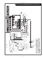
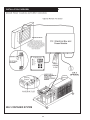
1
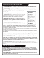
OTDX-FX1
FX-1 Control Panel for
Direct Expansion Systems
OPERATOR’S MANUAL
Technicold Marine Systems | www.technicold.com
Technicold by Northern Lights
1419 W. Newport Center Drive
Deerfield Beach, FL 33442
Tel: (954) 421-1717
Fax: (954) 421-1712
Copyright ©2012, Northern Lights, Inc.
All rights reserved. Northern Lights, Technicold,
the Northern Lights logo, and the Technicold logo are
trademarks of Northern Lights, Inc.
Printed in U.S.A.
PART NO.: OTDX-FX1 05/13
OPERATOR'S MANUAL
OTDX-FX1
for FX-1 Control Panel on Direct Expansion Systems
Read this operator's manual thoroughly before starting to operate your equipment.
This manual contains information you will need to run and service your new unit.
Table of Contents
INTRODUCTION ..............................................................................................................2
BASIC OPERATION .......................................................................................................3
SYSTEM OVERVIEW .......................................................................................................4
OPERATOR CONTROLS & DISPLAY PANEL ................................................................5
DUAL BUTTON FUNCTIONS ..........................................................................................6
SPECIAL BUTTON FUNCTION .......................................................................................7
MODES OF OPERATION .................................................................................................7
FAN MODES .....................................................................................................................8
ENTERING THE PROGRAM MODE ................................................................................9
PROGRAMMABLE PARAMETERS ...............................................................................10
PROGRAMMING .....................................................................................................11 - 13
FAIL-SAFE AND FAULT HANDLING CODES ...............................................................13
AUTOMATED FACTORY SELF TEST PROGRAM ........................................................14
SPECIFICATIONS....................................................................................................14 - 15
HOUR METER ................................................................................................................15
SERVICE HISTORY .......................................................................................................16
DIGITAL CONTROLS .....................................................................................................16
WIRING DIAGRAMS................................................................................................17 - 21
INSTALLATION OVERVIEW ..........................................................................................22
WARRANTY INFORMATION ...................................................................................23 - 24
Proprietary Information
This publication is the property of Northern Lights, Inc.
It may not be reproduced in whole or in part without the written permission of Northern Lights, Inc.
© Northern Lights, Inc. All right reserved.
Every precaution has been taken in the preparation of this manual to insure its accuracy. However, Technicold by Northern Lights
assumes no responsibility for errors and omissions. Neither is any liability assumed for damages
resulting from the use of this product and information contained herein.
Litho U.S.A. Publication number OTDX-FX1 05/13
1
INTRODUCTION
The FX-1 DX Control is designed for use with Marine DX Cooling and Heating Systems.
The FX-1 DX Control has a universal power supply that operates on 115, 230, 50 or 60 Hz AC power.
The FX-1 DX Control includes the following standard and optional features:
STANDARD FEATURES
• User friendly 4 button display panel requires no
manual for basic operation.
• Five volt logic and micro controller located in the
display.
• 3-digit 7-segment display indicates ° F or ° C.
• Room temperature sensor.
• Fan speed is adjusted automatically as the set
point is approached in cooling.
• Six [6] programmable manual fan speeds.
• 17 programmable parameters for custom installations.
• Away Mode for controlling relative humidity.
• Universal AC power supply.
• Nonvolatile memory retains settings without batteries.
• Programmable display brightness control for night use.
• High and low pressure switch inputs.
• AC voltmeter to protect equipment from low voltage
occurrences.
• Programmable time delay for staging multiple
compressors.
• De-Icing cycle to prevent evaporator coil icing.
I M P O R TA N T !
Face Plate Sensor Location
If the optional Display Panel air sensor is used, the
display MUST be located on an inside wall, NOT in
direct sunlight.
If these conditions cannot be met a remote air sensor
must be installed in the return air stream.
OPTIONAL FEATURES
The following optional items can be added by plugging the device into the appropriate jack and
making the necessary programming changes.
Alternate air temperature sensor (No programming needed)
Outside air temperature sensor (No programming needed)
Pump Sentry service sensor (Program P9 to On and set temperature)
Read This Manual Completely Before Proceeding!
This manual is intended to provide information necessary to insure proper installation and operation of
the FX-1 Control. Poor installation and misunderstood operating parameters will result in unsatisfactory
performance and premature failure of the FX-1 DX Control.
If you require assistance prior to or during the installation of the FX-1 DX Control call
Technicold by Northern Lights at 945-421-1717 or via email at [email protected].
The FX-1 Direct Expansion Control is covered under existing Technicold Warranty Policy.
Incorrect installation, neglect and system abuse are not covered under Technicold's warranty policy.
OTDX-FX1 5/13
2
BASIC OPERATION
ON/OFF POWER BUTTON Press the power button once to toggle the unit to the ON mode. Press
the power button again to toggle the unit to the OFF mode.
UP BUTTON Momentarily press and the
set point will appear in the temperature
display. The set point increases one
degree each time the up button is
pressed and released.
DOWN BUTTON Momentarily press and
release to display the set point. The set
point is decreased one degree each time
the down button is pressed and released.
SELECT BUTTON The select button is
used to select one of four [4] Operating
Modes. Press and release to advance
to the next mode. Continue to press and
release until the desired Operating Mode
is reached. The mode selected is indicated by the Mode LED.
THREE DIGIT DISPLAY The inside Air temperature is displayed whenever the control is turned on.
The display provides a read out of the inside air temperature.
COOL MODE LED The cool mode LED is lit when the Cooling is selected.
HEAT MODE LED The heat mode LED is lit when Heating is selected.
AUTOMATIC LED The automatic LED is lit when the Automatic Heating or Cooling Mode is selected.
The control will automatically switch to heating or cooling when this mode is selected.
AWAY MODE LED The away LED is lit when the Away Mode [ Humidity Control ] is selected.
AUTO FAN SPEEDS The fan speeds are automatically controlled as the set point is approached.
FAN SPEED BAR GRAPH There are six [6] individual fan speed LED's. Each LED represents one [1]
fan speed. Low fan [1] is indicated by illuminating the first LED. High fan speed is indicated by
illuminating all six [6] LED's.
MANUAL FAN SPEEDS Manual fan speed settings are available via system programming. See the
first programming item on page 10.
OPERATING LED The system operating status [ compressor on or off ] is indicated by the
operating LED.
READY LED The Ready LED is illuminated when the breaker is turned on and power is applied to
the control. It remains on whether the power button is in the On or Off mode.
OTDX-FX1 5/13
3
OVERVIEW
FX-1 DX Control is a user friendly, easy to operate, programmable temperature control. Press the ON/
OFF button once to engage the system. The display indicates room temperature when the system is
on and the display is blank when the system is off.
Press and release the Select Button until the desired Mode LED is illuminated. Set the room
temperature by pressing the up or down button. The set point can be viewed by momentarily pressing
and releasing the up or down button.
Fan speed automatically adjusts as room temperature is approached. In the cooling mode, the fan
speed decreases as the set point is approached. The fan will operate at low speed when set point
is satisfied. Manual fan speeds can be selected by entering the program mode and selecting the
desired manual fan speed. The fan will operate at the speed selected and will not change speeds
with room temperature. See page 9 of this manual for programming instructions.
The fan can be programmed to cycle on and off with demand, allowing the fan to run only when
cooling or heating is required. It is not recommended to cycle the fan on and off with demand. To do
so can affect system operation and comfort levels. The fan cannot be cycled when using a return air
sensor. Normally the automatic fan speed operation is reversed in the heating mode, however, the
fan can be programmed to operate the same as in the cooling mode.
NORMAL HEATING OR COOLING CYCLE
Select Cool only and only cooling will be supplied. The cabin temperature will be maintained
within 2 ° F of the set point. Select Heat only and only heating will be supplied. The cabin
temperature will be maintained within 2 ° F of the set point.
Select Automatic and both heating and cooling will be supplied as required. While in the
Automatic mode FX-1 will maintain a two degrees Fahrenheit (2 ° F) temperature variation. A four
degree swing is required to cause the unit to shift into the opposite mode. Once in a given mode,
heating or cooling, FX-1 will maintain a two degree differential
REVERSING VALVE OPERATION
The reversing valve is toggled to the opposite mode when heating or cooling is required to reduce
the compressor starting surge. The valve will only toggle to the opposite mode when a cooling or
heating cycle is called for and if the system has been off for less than seventy-five (75) seconds.
The valve will also toggle if a cycle is interrupted from the display panel by pressing the power
button ON/OFF, or changing the set point. Unnecessary valve toggling has been limited to reduce
reversing valve noise. Valve toggling can be totally eliminated by programming the minimum
compressor staging delay at seventy-five (75) seconds or greater.
Power on Reset, which occurs when the system is powered up, will always initiate a valve toggle.
Memory: FX-1 has nonvolatile memory which required no batteries or any form of backup
power. When power is lost the operating parameters are retained indefinitely. When the power
is restored, the control resumes operating as last programmed. All operating and programming
parameters are entered into nonvolatile memory instantly and are retained indefinitely.
OTDX-FX1 5/13
4
OPERATOR CONTROLS AND DISPLAY PANEL
Refer to figure 1 for the button locations and display functions listed on the following pages.
5
9
6
7
10
11
4
8
3
1
2
Figure 1: FX-1 Control Buttons and Indicator Displays
1. POWER BUTTON The power button is used to toggle between the on and off modes. Press the
power button once to toggle the unit to the on mode. Press the power button again to toggle to the
off mode.
2. DOWN BUTTON Momentarily press and release the down button to display the set point. Press
and release the down button to decrease the set point. The set point is decreased one degree
each time the down button is pressed and released. The lowest set point allowed is 55 °
Fahrenheit. The down button is used in conjunction with the up button to display outside air
temperature when the control is on. The down button is also used to reduce program values in the
program mode.
3. UP BUTTON Momentarily press the up button and the set point will appear in the temperature
display. Press and release the up button to increase the set point one degree. The set point is
increased by one degree each time the up button is pressed and released. The highest set point
allowed is 85 ° F. The up button is used with the down button to display the outside air
temperature when the control is on. The up button is also used to increase program values in the
program mode.
4. SELECT BUTTON The select button is used to select one of the four operating modes. Press
and release the select button and the FX-1 will advance to the next mode. Continue to press and
release the select button until the desired operating mode is reached. The mode selected is
indicated by the Mode LED, i.e., Cool, Heat, Automatic or Away Mode.
OTDX-FX1 5/13
5
OPERATOR CONTROLS AND DISPLAY PANEL
5. COOL MODE LED The cool mode LED will be lit when the Cooling Mode has been selected.
6. HEAT MODE LED The heat mode LED will be lit when the Heat Mode has been selected.
The heat mode LED is also lit when the optional electric heat is installed and the heat mode is
selected. Electric heater status, on or off, is indicated by the
Operating LED.
7. AWAY-MODE LED The Away Mode LED will be lit when the
Away Mode has been selected. This mode is used to control
moisture during periods when the vessel is unoccupied.
8. READY LED The Ready LED is on whenever AC power is
supplied to the control. The ready LED remains on whether the
control is in the On and Off modes.
9. THREE DIGIT SEVEN SEGMENT DISPLAY The inside air
temperature is displayed in the window whenever the control is
turned on. The three digit 7 segment display provides a readout of the inside air temperature
which is located on the face plate. An optional alternate air sensor is available for installations
that cannot use the face plate sensor.
The display also indicated program information, fault codes and outside air temperature when the
optional outside air sensor is installed.
The display will momentarily indicate the set point when either the up or down button is pressed
and released.
When the control resumes operation after a power interruption all the display LEDs will turn in for
one second. This is a normal operating condition and is referred to as "Power On Reset"/
10. FAN SPEED BAR GRAPH There are six [6] individual fan speed LED's in the Fan Speed Bar
Graph. Each LED represents one [1] fan speed. Low fan speed [1] is indicated by illuminating the
first LED. High fan speed is indicated by illuminating all six [6] LED's. Any of the six [6] fan speeds
available are displayed by illuminating the appropriate LED's.
11. OPERATING STATUS LED The Operating LED is on when the compressor is on and off,
when the compressor is off. The Operating LED also indicated when the optional electric heater is
turned on.
DUAL BUTTON FUNCTIONS
Up & Down Buttons Press the up and down button together and the outside air temperature will be
displayed, providing the OPTIONAL OUTSIDE AIR TEMPERATURE SENSOR has been installed. No programming is
required. Press the Up & Down buttons simultaneously, while in the program mode, to set new custom
programming defaults.
Power & Down Buttons Simultaneously press the power and down buttons while viewing the Service
Fault History Log clears the fault History Log.
OTDX-FX1 5/13
6
SPECIAL BUTTON FUNCTIONS
Special button functions are implemented by pressing and holding a particular button while the
controls' AC power is turned on.
1. Service History Log View the service history log by pressing and holding the select button
while turning on the AC power. Exit the service history log by pressing the power button once.
Clear the service history log by simultaneously pressing the power and down buttons.
2. Self Test Mode Press and hold the power button while AC power is applied to enter the
self test mode. The self test mode is used to diagnose problems and test the air conditioning
system. For complete details see page 14 of this manual.
3. View Hour Meter To view the compressor hour meter, press and hold the down button
while applying AC power. Maximum recorded time is 10,000 hours. The hour meter stops at
maximum (10,000 hours) and can only be reset by Technicold. The hour meter functions are
described fully on page 15 of this manual.
MODES OF OPERATION
Off Mode
When the FX-1 is in the Off Mode, all control outputs are turned off. Program parameters and
user settings are saved in nonvolatile memory. The program mode can only be accessed from the
off mode. The Ready LED remains lit in the off mode.
On Mode
When the control is in the On Mode, power will be supplied to the appropriate control outputs and
the display will indicate the current state of operation. The operating and program parameters
resume based on those stored the last time the unit was operating.
Cool Only Mode
When Cool LED is on, only the cooling systems are selected and operated as required. When the
temperature drops below the set point, the system will not automatically switch to the heating
mode. Cooling only is available for customers what do not want automatic cooling and heating
operation. Systems without reverse cycle heating can have an optional electric heater installed
should heating be required..
Heating Mode Only
Heating only is supplied for customers that require the system to not automatically switch from
the heating to the cooling mode. When the Heat LED is on, only the heating systems are selected
and operated as required. Should the temperature rise above the set point, the system will not
automatically switch to the cooling mode.
Automatic Mode
When the Automatic LED is on, both heating and cooling are supplied as required. The heat
and cool LEDs will be lit according to the mode required. When the system requires compressor operation for heating or cooling the Operating LED will turn on when the compressor is on.
Temperature in a given mode will be maintained at two degrees Fahrenheit ( 2 ° F), however, a
four degree difference is required to allow the control to change modes. Once in a new mode, the
temperature will remain within two degrees Fahrenheit ( 2 ° F ) of the set point.
OTDX-FX1 5/13
7
MODES OF OPERATION (Cont'd)
Away Mode
While in the On Mode, press the Select Button until the Away Mode LED is illuminated. The first
cycle will start in one minute. Every four (4) hours, the fan is started and air circulated for thirty
(30) minutes. During this time the air temperature is sampled and entered into memory. The
cooling cycle is started and continues until the temperature is lowered 2 ° F. The compressor is
allowed a maximum of one hour running time to reach the desired temperature. Four (4) hours
after the temperature is satisfied or the compressor times out, the cycle is repeated. During the
humidity cycle the Operating LED is lit while the compressor is running..
FAN MODES
Automatic Fan Mode
FX-1 has six automatic fan speeds available. Speed six is high,
three is medium and one is low or the lowest speed. Automatic
fan mode allows the FX-1 to determine the required fan speed
based on room temperature. The closer the room temperature is
to the set point, the slower the fan will run. This permits a
balance between the most efficient temperature control and
slower, quieter fan speeds. Automatic fan operation is the factory
default, however, manual fan speed control is available.
Manual Fan Mode
Program parameter one [1] is used to select one of the six [6]
manual fan speeds available. Six [6] is the fastest and one [1]
represents the slowest fan speed. Manual fan mode allows the
user to select and maintain the desired fan speed manually.
When a manual fan speed has been selected, the fan speed bar
graph will indicate the speed selected by the number of LED's
lit. Select speed 3, for example, and the first 3 LEDs in the fan
bar graph will turn on. Manual Fan Mode is sometimes preferred
when room temperature is constantly changing due to varying
heat loads.
PROGRAM MODE
Program Mode Overview
The program mode is used to adjust the systems operating
parameters to suit the particular needs of individual users.
The program mode is also used to tailor the air-conditioning
system for the most efficient operation within an installation.
Installation variables such as ducting, sensor location and
system layout effect the perceived operation of the overall
system. The program mode allows the system to operate
as efficiently as possible under all conditions. The FX-1 is
shipped with factory programmable default settings which are
stored in permanent memory and can be recalled at any time.
OTDX-FX1 5/13
8
PROGRAM MODE (CONT'D)
Severe electrical disturbances can sometimes upset the FX-1 operating sequences. Operator confusion related to
program parameters can also cause, what seem to be, operational problems. Whenever there is any doubt as to
the proper operation of the controller, Factory Default Parameters should be Re-initialized.
ENTERING PROGRAM MODE
The Program Mode can only be entered from the Off Mode. From the off mode
and in the following order, press the Select, Up, Down and the Select buttons.
These buttons have to be pressed and released in the order given. The letter
"P" appears in the display. The buttons have to be pressed in the sequence
described. Remember "SUDS"… It's the key to enter and unlock the program
mode. The characters "P" then "P 1" followed by the parameter setting, appear in
the display. The FX-1 is now in the program mode. Exit the program mode to the
Off Mode, by pressing and releasing the power button.
NOTE: The control will exit the program mode and return to the off mode if no
programming is attempted for one [1] minute.
Restore Memorized Default Settings
IMPORTANT! The memorized default settings can be restored by entering the
program mode and setting P-17 to rSt. Exit the program mode and the software
version number appears in the display. The memorized default settings are
restored and the FX-1 returns to the off mode. The software version number is
always displayed when you exit the program mode.
USING THE PROGRAM MODE
Increment from one program parameter to the next by pressing the select button while in the
program mode. Press and release the select button to advance to the desired parameter. Use
the up and down buttons to change the program parameter values. The programmable
parameters range from P-1 through P-17.
Up and Down Buttons
The up and down buttons are used to select the data or set the desired limits for the parameter
being programmed. This method is followed throughout the program mode, however, special
instructions are included for individual functions as required.
Exiting the Program Mode
There are two methods to exit the program mode. Press the power button and the FX-1 control
will return to the off mode. Not pressing any buttons or attempting any program changes for sixty
(60) seconds will allow the control to exit the program mode to the off mode. Any programming
changes that were made while in the program mode will be memorized and put into operation
when the program mode is exited and the control is returned to the on mode.
Software Identification
The software version of the control is identified for one [1] second prior to the exit from the
program mode. The software identification number, i.e. ["A10"] will appear in the display for one
second, then the control will return to the off mode.
Should there be any reason to contact Technicold about the system or programming the
FX-1 be sure to have the software identification number available.
OTDX-FX1 5/13
9
PROGRAMMABLE PARAMETERS
There are seventeen (17) programmable parameter locations with their Factory Default
Settings listed in this section. The table below describes these parameters, along with the
permitted values and the original Factory Default Settings..
Program #
Description
P-1
Fan Speed operation: Auto or Manual
P-2
P-7
High Fan Speed Limit
(arbitrary units)
Low Fan Speed Limit
(arbitrary units)
Compressor Staging Time Display
Temperature Sensor Calibration
Failsafe Modes and Mnemonic
High Freon Pressure - HPF
Low Freon Pressure - LPF
Low AC Line Voltage - LAC
Low AC Voltage Cut-Off
P-8
De-Icing Cycle
P-9
P-10
Pump Sentry - Protect Pump and
Compressor From Loss of Sea Water
Display Brightness Control
P-11
Display o Fahrenheit or o Celsius
P-12
Cycle Pump With Compressor or
Continuous Pump
Reverse Fan Speeds During Heating
Mode
Continuous Fan or Cycle Fan with
Compressor
Reverse Cycle Heating or Electric
Heat
Fan Motor Type Selection - Shaded
Pole or Split Capacitor
Reset Memorized Programming
Defaults
P-3
P-4
P-5
P-6
P-13
P-14
P-15
P-16
P-17
Default
A=Automatic
85
Range
A=Automatic
1 thru 6 Manual Speeds
65-95
55
30-64
15
0
3 = 4 Failures with 90 second
restart delay. Manual reset is
required.
5 - 135 seconds
Ambient - 10o F
off
1 = Continuous No Display
2 = Continuous With Display
3 = 4 Failures Reset Required
85 VAC (115 vac)
Off - 75 to 120 (115 vac units)
185 VAC (220 vac)
Off 175 to 220 (220 vac units)
0
0 = Off
1 to 3 Minutes
OFF
OFF
On = Select 100o F to 150o F
13 = Maximum
4 = Low
13 = Maximum
oF
o F = Fahrenheit Displayed
o C = Celsius Displayed
OFF = Cycle With Compres- OFF = Cycle With Compressor
sor
On = Continuous Pump
rEF = Reversed
nor = Normal Fan Operation
rEF = Reversed Fan In Heating
con = Continuous Fan OperaCYC = Cycle Fan On Comp.
tion
con = Continuous Fan Operation
nor = Reverse Cycle Heating
nor = Reverse Cycle Heating
ELE = Electric Heater Installed
SP = Shaded Pole
SP = Shaded Pole Fan Motor
SC = Split Cap. Fan Motor
nor = Normal
rSt = Reset Defaults
Should any programming problems or confusion occur, reset the Memorized Default Settings by
entering the program mode and setting P-17 to rSt.
OTDX-FX1 5/13
10
PROGRAMMING
P-1: FAN SPEED AUTOMATIC OR MANUAL
P-5: TEMPERATURE CALIBRATION
The program values allowed are A, followed by
one (1) through six (6). Select "A" (factory default
setting) for automatic fan speeds and the fan will
operate in conjunction with room temperature. The
further the room temperature is from set point, the
faster the fan will run in the cooling mode. The fan
speed will gradually decrease as the set point is
approached and the fan will run at low speed (1)
when the set point is satisfied. Select any one of
six (6) manual fan speeds available, for example,
select three (3) and the fan will operate at medium
speed under all temperature conditions. When a
manual fan speed is selected the fan will always
operate at the speed selected and will not vary with
room temperature.
Use this feature to calibrate the air sensor within
a range of ± ten (10) °F. Enter the program mode
and the ambient temperature appears in the
display. Use the up and down keys to select the
desired offset. The temperature in the display
will increase or decrease according to the offset
programmed.
The factory default setting is zero.
P-2: HIGH FAN LIMIT
The upper fan speed limit can be tailored to suit
various motors and operating conditions. The high
fan limit is adjusted with the system installed and
operational. The range of values are 56 through
85 and represent arbitrary units. Setting a higher
number, results in a higher fan speed, setting lower
numbers, lowers the high fan speed limit. Use the
up and down buttons to select the desired high fan
speed limit. The factory default setting is eighty-five
(85).
P-6: FAIL-SAFE LEVEL
The system can be configured for one of four
fail-safe levels. Selecting OFF turns off all fail-safe
protection and mnemonic display codes. Level
one (1) shuts down the system, allows the system
to restart after a 90 second delay and displays no
failure code. Level two (2) shuts down the system,
allows continual restarts after the 90 second delay
and displays the appropriate mnemonic failure
code. Level three (3) operates the same as level
two with the addition of a system shutdown after
four (4) consecutive failures... Manual reset is
required to restart the system.
P-7: LOW AC VOLTAGE CUT-OFF
FX-1 can be programmed to protect the system
against sustained low AC line voltage conditions. The
compressor will be shut down and "LAC" flashed
in the display if the line voltage goes below the
P-3: LOW FAN LIMIT
programmed value for more than ten (10) minutes.
The low fan limit determines the lowest output
Programmable values are 75 VAC to 120 VAC for
allowed for the low fan speed. The range of values
120 volt units and 175 VAC to 220 VAC for 220 volt
for the low fan speeds are 30 through 55, in
systems. The factory default is 85 VAC for 120 volt
arbitrary units. Use the up and down buttons to
units and 185 VAC for 220 volt systems. NOTE: Low
select the desired low fan speed limit. Setting a
Voltage Protection can be turned off by programming
higher number results in a higher fan speed. Setting Off instead of selecting a voltage value.
lower numbers lowers the low fan speed limit. The
factory default setting is 45.
P-8: DE-ICING CYCLE
IMPORTANT ! Once the high and low fan speed
FX-1 is equipped with a De-Icing Cycle to prevent ice
limits are set, the unit will automatically readjust to
build up on the evaporator coil during extended
produce six [6] equally spaced fan speeds in both
periods of cooling operation. Installation variables
such as grille sizes, length of ducting, insulation R
the automatic and manual fan speeds modes.
factors and ambient temperatures determine the
cooling run time required to achieve set point.
P-4: COMPRESSOR STAGING TIME DELAY
Customer usage may substantially increase run
The compressor staging time delay is provided for
times by operating the system with the hatches and
installations where more than one system is being
doors open. Programming unrealistic set point [55o
operated from the same power source. Setting the
staging delays at different intervals allows only one F] and leaving the salon door open will usually cause
the evaporator to ice up on warm, muggy days.
compressor to start at a time. The units should be
De-Icing is accomplished by switching the reversing
staged at least five (5) seconds apart. The
valve into Heat Mode while the system is cooling.
minimum delay is five (5) seconds and the
maximum is one hundred thirty-five (135) seconds. The valve will remain energized for the programmed
cycle time. The factory default setting is zero [Off].
The factory default setting is 15 seconds.
OTDX-FX1 5/13
11
PROGRAMMING
P-9: OPTIONAL PUMP SENTRY
FX-1 can be equipped with an optional temperature
sensor that is used to monitor the condenser coil
temperature. The sensor is plugged into the outside
air sensor jack and parameter P-9 programmed for a
temperature between 100 and 150 o F depending on
sea water temperature and the system type. When
the coil temperature rises above the programmed
value, the pump and compressor are shut down and
"PPP" is flashed in the display. The factory default is
Off, no pump sentry installed.
The factory default is rEF, which reverses the
automatic fan speeds during heating.
P-14: CYCLE FAN WITH COMPRESSOR
The fan can be programmed to run continuously when
the system is on or can be allowed to cycle with the
compressor. When cycled with compressor, the fan
will operate only when heating or cooling is called for.
To cycle the fan with the compressor select CYC. To
operate the fan continuously select "con". The
factory default when the system is on is continuous
fan operation [con].
P-10: DISPLAY BRIGHTNESS CONTROL
The display brightness can be adjusted to suit
ambient cabin lighting conditions. The allowed
settings are four (4) to thirteen (13), with four (4) being
the dimmest and thirteen (13) the brightest. Typically
a dark cabin will require a setting of four or five. A very
bright cabin will require a setting of twelve or thirteen.
The factory default setting is thirteen (13).
P-15: REVERSE CYCLE OR ELECTRIC HEAT
Units not equipped with reverse cycle heat may have
electric heater added. Electric heat requires the
compressor be turned off when heating is called
for. The reversing valve outlet is used to control the
optional electric heating element contractor. The valve
output relay can only carry 6 amps, therefore, a heavy
duty contractor must be installed to carry the heater
current. Program parameter ELE for the electric heat
option. The factory default is nor which is normal
reverse cycle heating.
P-11: FAHRENHEIT OR CELSIUS SELECTION
The unit can be programmed to display either
Fahrenheit or Celsius. Programming °F selects
degrees Fahrenheit and programming °C displays
degrees Celsius. The factory default setting is °F,
Fahrenheit. When degrees Celsius (°C) is selected
the readings are displayed in tenths, i.e. 22.2 °.
NOTE: See addendum for electric heat option. Contact factory for more information.
P-12: CYCLE PUMP WITH COMPRESSOR
to increase pump life and conserve electricity the
pump can be programmed to cycle on and off with the
compressor. The pump can also be programmed to
operate continuously whenever the system is on. To
program the pump for continuous operation turn P-12
On. The factory default is Off, which cycles the pump
with the compressor.
P-16: FAN MOTOR SELECTION
There are two basic fan motor types, shaded pole and
split capacitor. Each motor reacts differently to speed
control and each motor requires different timing for
optimum fan speed variation. The default setting is
"SC" which selects the split capacitor motor type, however, "SP" should be selected if a shaded pole type of
fan motor is used in the system. Most air handlers are
supplied with split capacitor type fan motors. The factory default is "SC" split capacitor fan motor type.
P-13: REVERSE AUTOMATIC FAN SPEEDS
DURING HEATING
The automatic fan speeds can be reversed during the
heating mode to improve heat output in cooler
climates. The fan speed is decreased as the
temperature spread increases. The fan will speed up
as the set point is approached. Lowering the fan speed
when the cabin is cold raises the supply air
temperature. The fan switches to low speed when the
set point is satisfied and the water valve cycles off.
The fan can be programmed to operate the same as in
cooling by programming "P-13 nor" which represents
normal fan operation during the heating cycle.
P-17: RESET MEMORIZED DEFAULTS
The default programming parameters can be reset by
entering the program mode and selecting rSt. This will
restore the programmable parameters to the values
selected when the system was shipped. The program
parameters listed on page 9 may be altered by
Technicold, the installing dealer or the end user. Once
new defaults are entered (see page 6, dual button
functions) and memorized the NEW defaults will be
reset. The original factory programmable parameters
as listed on page 9 will have to be restored manually.
OTDX-FX1 5/13
12
PROGRAMMING
Why Memorize New Defaults?
Once the desired programming changes have been made and the system tests satisfactorily, your work can be
saved as the new factory defaults. Your new defaults are initiated by simultaneously pressing and releasing the
up and down buttons prior to exiting the program mode. New defaults can be initialized at any time by entering
the program mode and following the above instructions. Once new defaults have been initialized the control will
revert back to the new defaults whenever factory defaults are restored as described on page 8 of this manual.
FAIL-SAFE AND FAULT HANDLING CODES
When a fault is detected FX-1 will display one of the following Mnemonic fault codes:
HPF… indicates high Freon pressure. 15 Second Delay… Ignored in Heat Mode.
LPF… Indicates low Freon pressure. There is a ten minute charge time delay.
LAC… Indicates low AC line power
AAA… Indicates failed air sensor. Unit will not run until repaired.
PPP… Indicates the sea water pump has failed.
FAIL-SAFE
There are four levels of fail-safe protection including the fail-safe off mode. Level one monitors the
sensors, takes appropriate action and allows continuous restarts after a 90 second delay. Does not
display the fault code. Level two works the same as level one, however, the appropriate fault code
mnemonic is displayed during the time-out between restarts. Level three is identical to level two
with the inclusion of a four successive failures lockout routine. After four consecutive failures the
system is shut down and a manual reset is required.
LOCKOUT
Lockout occurs if P-6 is programmed for level 3 and four consecutive faults are detected within
a heating or cooling cycle. Lockout causes the system to shut down and flash the mnemonic fault
code. Lockout can only be cleared by turning the unit off, then on using the power button.
FAULT DISPLAY
When a fault occurs the appropriate mnemonic code is flashed in the display. The flashing
mnemonic can be removed from the display by pressing and releasing the power button to reset the
control. Resetting the control does not solve the problem that caused the fault!
Failsafe
Level
OFF
Action
Description of Action Taken
All Protection
Turned Off
FAILSAFE PROTECTION LEVELS TURNED OFF:
Air Sensor Fault: Heating/Cooling Immediately Suspended; Normal
Operation Not Resumed Until Fault is Cleared. Air Sensor Fault Code
"Flashing Display" NO OTHER FAILSAFE PROTECTION PROVIDED.
1
No Mnemonic Fault
Code Displayed
Continuous 90 Sec.
Re-Starts Allowed!
MINIMUM PROTECTION LEVEL:
All Actions Taken in Failsafe Protection Level "0" Plus: In Addition,
Continuous 90 Second Compressor Restarts Allowed.
FAULT Mnemonic CODE NOT DISPLAYED
NO OTHER FAILSAFE PROTECTION PROVIDED.
2
Display Fault & Shut
Down Compressor
With Continuous 90
Second Delay
Between Restarts.
INTERMEDIATE PROTECTION LEVEL:
All Actions Taken in Failsafe Protection Level "0" & Level "1" Plus: In
Addition, The FAULT MNEMONIC CODE Message Will Be
Displayed With Continuous 90 Second Compressor Restarts
3
Display fault &
require manual reset
after 4 failures.
MAXIMUM PROTECTION LEVEL:
FAULT CODE MESSAGES ARE DISPLAYED and The Appropriate
Action is Taken According to The Problem Encountered. After 4
Consecutive Failures Manual Reset is Required.
OTDX-FX1 5/13
13
AUTOMATED FACTORY SELF-TEST PROGRAM
SELF-TEST MODE
The FX-1 software contains a self-test program to facilitate factory testing of the entire air conditioning system. Once the self-test mode is activated, the test cycle will continue until the AC power is
interrupted or the on/off button is pressed once which returns the system to the off mode.
Activate the self-test by pressing and holding the on/off button while turning on the AC power. Be
sure to continue to hold the button until the power on reset is completed. FX-1 is now in the self test
mode.
Once activated the self-test software will continuously execute the following procedure:
1 - Turn on in the heat mode and supply heating for ten (10) minutes.
2 - Stop heating and run the fan only for five (5) minutes.
3 - Switch to cooling and continue cooling for ten (10) minutes.
4 - Stop cooling and run the fan only for five (5) minutes.
5 - Return to step one (1) and continue until interrupted.
The test mode will continue until the power is interrupted or the test is halted by pressing the on/off button once.
SPECIFICATIONS
SET POINT OPERATING RANGE...............................................................................55 ° F TO 85 ° F
AMBIENT TEMPERATURE OPERATING RANGE DISPLAYED ................................55 ° F TO 85 ° F
SENSOR ACCURACY ................................................................................................ ± 2 °F AT 77 ° F
LOW VOLTAGE LIMIT 115 VOLT UNITS ................................................................................. 75 VAC
LOW VOLTAGE LIMIT 220 VOLT UNITS ............................................................................... 175 VAC
LOW VOLTAGE PROCESSOR RESET ................................................................................... 60 VAC
LINE VOLTAGE .............................................................................................115 THROUGH 250 VAC
FREQUENCY .................................................................................................................. 50 OR 60 HZ
FAN OUTPUT ...................................................................................................... 6 AMPS @ 115 VAC
FAN OUTPUT .......................................................................................................6 AMPS @ 230 VAC
VALVE OR HEATER OUTPUT..............................................................................1/4 AMP @ 115 VAC
VALVE OR HEATER OUTPUT..............................................................................1/4 AMP @ 230 VAC
PUMP OUTPUT ......................................................................................................1/4 HP @ 115 VAC
PUMP OUTPUT ......................................................................................................1/2 HP @ 230 VAC
COMPRESSOR OUTPUT .........................................................................................1 HP @ 115 VAC
COMPRESSOR OUTPUT ........................................................................................ 2 HP @ 230 VAC
MINIMUM OPERATING TEMPERATURE .....................................................................................0 ° F
MAXIMUM AMBIENT OPERATING TEMPERATURE ...............................................................180 ° F
MAXIMUM RH CONDITIONS ..................................................................... 99% NON CONDENSING
POWER CONSUMPTION .................................................................................LESS THAN 5 WATTS
SPECIFICATIONS
DIMENSIONS
DISPLAY PANEL ............................................................................................................. 3.75" X 3.75"
PANEL CUT OUT ........................................................................................................ 3.150" X 3.150"
OTDX-FX1 5/13
14
CABLE LENGTHS
SELF CONTAINED DISPLAY CABLE...........................................................................15' STANDARD
ALTERNATE AIR SENSOR ........................................................................................... 7' STANDARD
PUMP SENTRY SENSOR .............................................................................................7' STANDARD
SYSTEM INPUTS
1 .................................................................. AMBIENT FACE PLATE AIR TEMPERATURE SENSOR
1 .................................................................................................................HIGH FREON PRESSURE
1 ................................................................................................................. LOW FREON PRESSURE
1 ...................................................................... OPTIONAL OUTSIDE AIR TEMPERATURE SENSOR
NOTES: Custom cable lengths available on special request in 5 foot increments. Maximum length
of display cable is fifty ( 50 ) feet. Sensor cable lengths should be limited to 50 feet. The outside
air sensor, alternate air sensor and condenser coil sensor are optional items and are not included
with the standard control package.
When installing the optional Pump Sensor [ Pump Sentry ] and the Alternate Air Sensor No Outside
Air Sensor is available.
In order to continually improve and advance the FX-1 Control, Micro Air, Inc. reserves the right to
change this product's basic operation, specifications and design criteria without prior notice.
HOUR METER
Total compressor cycle time is saved in EEPROM every 6 minutes of continuous compressor
running time. Cycles less than 6 minutes will be discarded to conserve memory and allow the
most flexible hour-meter possible.
To view the hour meter turn off the power at the AC breaker and hold the down button depressed.
While depressing the down button, restore AC power. After the Power-On reset routine is
complete, the following will appear in the display:
HOUR METER
THOUSANDS
HUNDREDS
1. The hour meter mnemonic [Hr] is displayed for
one [1] second.
2. The display blanks out for one second and then
displays the Thousands units for three [3] seconds.
3. The display blanks out for one [1] second and then displays the Hundreds units for three [3]
seconds.
4. The unit returns to the last operating state before power was removed.
The example shown is displaying eleven-hundred twenty-two [1,122] hours.
Maximum recorded time is 10,000 hours. The hour meter stops at maximum (10,000 hrs) and
can only be reset by Technicold.
OTDX-FX1 5/13
15
SERVICE HISTORY
FX-1 will record and remember the last eight (8) service problems or service faults detected. Each
time a fault is detected, a one hour timer is started. During that hour the same recurring fault will
not be recorded. Should a different fault be detected during that hour, it will be entered into the
service history log.
The following events are entered into the service history log:
1. High Freon Pressure
2. Low Freon Pressure
3. Air Sensor Fault
4. Low AC Voltage
5. Pump or Loss of Sea Water Fault
To view the service log turn off the AC power and depress the select button. With the select
button depressed turn on the AC power. Once Power-On reset is completed, the display will
flash the most recent mnemonic for the fault detected, followed by the event number. To view
the other events detected press either the up or down buttons.
To exit the service history log press the power or the select button or wait 30 seconds without
pressing any buttons.
The service log can be cleared by simultaneously pressing the power and down buttons while you
are viewing the service log mode.
DIGITAL CONTROLS
OTDX-FX1 5/13
16
FX-1 WIRING DIAGRAM
OTDX-FX1 5/13
17
revised 6-15-12
FX-1 WIRING DIAGRAM
OTDX-FX1 5/13
18
added 6-15-12
DX UNIT WITH FX-1
OTDX-FX1 5/13
19
P
C
B
3
6
0
0
0
F
FX-1
PWR
AC
L-1
AC
L-2
COMP
RUN-L2
COMP
COM-L1
DISPLAY
PUMP
L-1
PUMP
L-2
USED FOR
PUMP SENTRY
OUTSIDE
OTDX-FX1 5/13
20
VALVE
L-1
JP9
1
2
3
FAN
L-1
JP8
SERVICE FREON
JP7
FAN
L-2
JP11
ALT. AIR
P
U
R
Y
E
L
B
L
K
FX-1
FX-1 Maxx
FX-1 Hideaway
"FX Series" JUMPERS CONFIGURATION FOR
FX-2 CIRCUIT BOARD:
JP9 IS INSTALLED
JP11 PINS 2 AND 3 ARE SHORTED
JP7 REMOVE FOR LP
JP8 INSTALLED FOR DX
added 5-8-13
FX-1 DISPLAY WITH FX-2 CIRCUIT BOARD
added 5-9-13
SPLIT DX - DUAL EVAPORATORS WITH FX-1 DISPLAY & FX-2
OTDX-FX1 5/13
21
INSTALLATION OVERVIEW
OTDX-FX1 5/13
22
WARRANTY INFORMATION
The Limited Warranty applies to the following product lines:TECHNICOLD Air Conditioning and Refrigeration Products
Technicold manufacturer NORTHERN LIGHTS, INC. (herein “NLI”) extends to the purchaser and user (herein “Owner”) of the product
the following limited warranty (herein “Warranty”). Please read it carefully.
Technicold Air Conditioning
and Refrigeration Products
Warranty Period......
Product
12 Months
Parts and Labor
12 Months
Parts
24 Months
NLI’S WARRANTY AND RESPONSIBILITIES
Subject to the terms and conditions set out below, The obligation of this Warranty shall be limited
NLI warrants the product and its factory installed to repairing or replacing any part of the product
which NLI agrees is defective in materials or
parts to be free from defects in material and
workmanship under normal use and service
workmanship under normal use and service.
If the product is purchased for and used primarily in during the warranty period. If during the
a commercial endeavor, the Warranty period shall warranty period the product or any of its parts are
extend from the date of delivery to the original end found to be defective because of workmanship or
user for a period of twelve (12) months with no limit materials, it will be repaired or replaced without
on hours of use. If the product is purchased for and charge if the Owner prepays the transportation
used primarily in personal, family or household use, charges and returns the item to NLI’s authorized
the warranty period shall extend from the date of warranty dealer. To find the location of the
delivery to the original end user for a period of twelve nearest NLI authorized warranty dealer, contact
(12) months with no limit on hours of use. Original NLI at the address, e-mail address, or telephone
parts shall be warrantied for a period of twenty-four or fax numbers in this publication.
(24) months from date of delivery.
Upon request by the Owner and agreement by
NLI, repair of product or replacement of parts
under this Warranty may be completed at a place
other than at an NLI authorized warranty dealer.
See “Owner’s Responsibilities”.
NLI’S WARRANTY AND RESPONSIBILITIES
Within thirty (30) days of purchase, Owner or If pre-approved repair of product or replacement of
authorized agent of Owner must complete, sign parts under this Warranty is completed at a place
and deliver to NLI the Warranty Registration Card in other than an NLI authorized warranty dealer,
order to validate this warranty. Owner must break Owner shall pay NLI’s or its authorized dealer’s
in unit as described in the “Operating Procedures” reasonable travel expenses.
section of the Operator’s Manual.
Owner shall pay costs of any labor required to
At the time of presentation of product for service remove and reinstall the product and/or parts
under this Warranty, the Owner or authorized agent thereof, any premium for overtime labor requested
must present evidence of the date of original
by the Owner and costs for transporting the
purchase of the product.
product and/or parts thereof to and from the place
where warranty work is performed.
OTDX-FX1 5/13
23
WARRANTY INFORMATION
WARRANTY LIMITATIONS
This warranty will not apply to equipment put into This Warranty is transferable to a new Owner
service more than twenty-four (24) months from date during the warranty period. No transfer forms or
of shipment from factory, and will not apply in any fees are required.
country with which trade is restricted or banned by This Warranty does not extend to failure resultthe U.S. Department of State, at or after the time ing from an accident or disaster or from Owner
of sale or claim.
or operator abuse or neglect (such as operating
without proper maintenance of equipment, includIf the product is used primarily in a commercial ing pumps, filters and electrical connections.)
endeavor, neither NLI nor any company affiliated Service parts worn out by usage and not due
with NLI will be liable for general damages,
to defects in workmanship or material are not
including bodily injuries, except as set forth above, covered by this Warranty.
or for incidental consequential damages, including, NLI is not responsible for failure resulting from
but not limited to, loss of use, loss of profits, loss improper repair or use of defective parts or parts
of production, expense of substitute equipment or not approved by NLI.
other commercial loss or for damage to property in NLI is not responsible for failure of product or
which equipment is installed. The same limitations parts resulting from improper installation or
shall apply to a product used for personal purposes unauthorized modifications.
with respect to all non-personal injuries, general, NLI is not responsible for failure caused by
incidental and consequential damages.
negligent handling or abuse in installation or
storage in improper environment which results
Some countries or states do not fully allow the above in corrosion or freezing damage to equipment.
exclusions or limitations of general, incidental or NLI is not responsible for failure caused by any
consequential damages, so the above exclusions third party’s transportation damage to NLI’s
or limitations may not apply to you.
product.
This Warranty extends only to the original parts, NLI is not responsible for damage if any warning
accessories and products.
alarm system is ignored.
NO REPRESENTATIONS AND LIMITATIONS OF IMPLIED WARRANTY
This written Warranty is in lieu of all other express
warranties, obligations or limitations. If this
equipment is used primarily in a commercial
endeavor, no implied warranty, including that of
merchantability and fitness for a particular
purpose is extended. If the product is used primarily
in personal, family or household use, any implied
warranty, including that of merchantability and
fitness for a particular purpose, shall be limited to
twelve (12) months.
Some countries or states do not allow limitations on
how long an implied warranty lasts, so the above
limitations may not apply to you.
No person is authorized to make any representations
or promised on behalf of NLI or to modify the terms
or limitations of this Warranty in any way except in
writing and signed by an authorized employee of NLI.
This warranty gives you specific legal rights, and
you may have additional statutory rights which vary
from one country or state to another.
OTDX-FX1 5/13
24
1419 W. Newport Center Drive, Deerfield Beach, FL 33442
Tel: (954) 421-1717 • Fax: (954) 421-1712
Northern Lights and Technicold are registered trademarks of Northern Lights, Inc.
www.technicold.com
© 2013 All rights reserved. Litho USA. OTDX-FX1