1
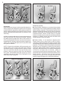
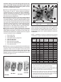
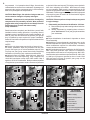
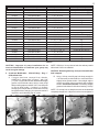
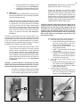
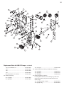
1
Instruction sheet No. 6250
Revised 10-28-98
S&S Cycle, Inc.
Copyright ©, 1986, 1995, 1996, 1998
by S&S Cycle, Inc.
14025 County Hwy. G P.O. Box 215
Viola, Wisconsin 54664
All rights reserved. Printed in the U.S.A.
Phone 608-627-1497
Fax 608-627-1488
email sstech@mwt. net
Technical Service
Installation Instructions for All S&S Big Twin Oil Pump Kits
Safe Installation and Operation Rules:
IMPORTANT NOTICE:
Before installing your new S&S oil pump it is your
responsibility to read and follow the installation and maintenance
procedures in these instructions and follow the basic rules below
for your personal safety.
● Gasoline is extremely flammable and explosive under
certain conditions and toxic when breathed. Do not smoke.
Perform installation in a well ventilated area away from open
flames or sparks.
● Compressed air and particles dislodged from using
compressed air are harmful to eyes and body. Wear protective
goggles when using compressed air and always direct air
stream away from body parts such as hands and eyes and
other people near you.
● Some solvents, degreasers and other chemicals are harmful
to skin, eyes and other body parts. Many items are flammable
and present a fire hazard. Read manufacturer's instruction
label for proper use. Use in well ventilated area and wear
protective clothing when using them to avoid personal injury.
● If motorcycle has been running, wait until engine and exhaust
pipes have cooled down to avoid getting burned before
performing any installation steps.
● Before performing any installation steps disconnect battery
to eliminate potential sparks and inadvertent engagement of
starter while working on electrical components.
● Read instructions thoroughly and carefully so all procedures
are completely understood before performing any installation
steps. Contact S&S with any questions you may have if any
steps are unclear or any abnormalities occur during installation
or operation of motorcycle with S&S oil pump on it.
● Consult an appropriate authorized H-D service manual for
correct disassembly and reassembly procedures for any parts
that need to be removed to facilitate installation.
● Use good judgement when performing installation and
operating motorcycle. Good judgement begins with a clear
head. Don't let alcohol, drugs or fatigue impair your judgement.
Start installation when you are fresh.
● For optimum performance and safety and to minimize
potential damage to oil pump or other components, use the
mounting hardware that is provided and follow all installation
instructions.
● Be sure all oil lines, supply and return, are routed correctly
with clamps in place and tightened. Lines must not contact
exhaust pipes or other extremely hot surfaces where they could
melt or leak and catch fire.
● Motorcycle exhaust fumes are toxic and poisonous and must
not be breathed. Run motorcycle in a well ventilated area where
fumes can dissipate.
Statements in this instruction sheet preceded by the following
words are of special significance:
WARNING
Means there is the possibility of injury to yourself or
others.
CAUTION
Means there is the possibility of damage to the oil pump
or motorcycle.
NOTE
Other information of particular importance has been placed
in italic type.
S&S recommends you take special notice of these
WARRANTY:
All S&S parts are guaranteed to the original purchaser to be
free of manufacturing defects in materials and workmanship for a
period of six (6) months from the date of purchase. Merchandise
that fails to conform to these conditions will be repaired or replaced
at S&S’s option if the parts are returned to us by the purchaser
within the 6 month warranty period or within 10 days thereafter.
In the event warranty service is required, the original purchaser
must call or write S&S immediately with the problem. Some
problems can be rectified by a telephone call and need no further
course of action. A part that is suspect of being defective must not
be replaced by a Dealer without prior authorization from S&S. If it
is deemed necessary for S&S to make an evaluation to determine
whether the part was defective, it must be packaged properly so
as to not cause further damage and be returned prepaid to S&S
with a copy of the original invoice of purchase and a detailed letter
outlining the nature of the problem, how the part was used and the
circumstances at the time of failure. If after an evaluation has
been made by S&S and the part was found to be defective, repair,
replacement or refund will be granted.
ADDITIONAL WARRANTY PROVISIONS:
(1 )S&S shall have no obligation in the event an S&S part is
modified by any other person or organization.
(2) S&S shall have no obligation if an S&S part becomes defective
in whole or in part as a result of improper installation, improper
maintenance, improper use, abnormal operation, or any other
misuse or mistreatment of the S&S part.
(3) S&S shall not be liable for any consequential or incidental
damages resulting from the failure of an S&S part, the breach of
any warranties,the failure to deliver, delay in delivery, delivery in
non-conforming condition, or for any other breach of contract or
duty between S&S and a customer.
(4) S&S parts are designed exclusively for use in Harley-Davidson
motorcycles. S&S shall have no warranty or liability obligation if
an S&S part is used in any other application.
2
#31-6001
#31-6073
#31-6003
#31-6003
#31-6006
Picture 1
Picture 1A
Introduction
S&S manufactures oil pumps in both cast and billet aluminum.
Cast oil pump kits are designed to replace stock H-D pumps
on all OHV Big Twin engines from 1936 to present except Twin
Cam 88. Cast pumps retain stock functions such as rear and
primary chain oiling. Billet pumps have no provision for rear
chain oiling.
IMPORTANT NOTES
● Chrome Plating - S&S does not recommend chrome plating
oil pump body or cover. Proper preparation for plating requires
abrasive buffing compounds. These materials can plug critical
passages and otherwise damage oil pump. Also, it is extremely
difficult to chrome plate an oil pump without altering critical
machined surfaces. Chrome in these areas or on gasket
surfaces can impair pump’s performance by altering operating
tolerances. In addition, chrome may flake and break loose
causing damage to pump and engine.
All S&S oil pumps provide same oil volume and pressure as
stock 1973 and later H-D pumps with stock gears. Installing
any S&S oil pump on engine from 1936 to 1967 results in a
33% increase in supplied oil volume over stock cast iron pump.
An additional 25% increase can be achieved on engines from
1939 to 1972 if optional S&S pinion and oil pump drive shaft
drive gears are installed.
NOTE - Except for Knuckleheads, S&S recommends use of
optional pinion and oil pump drive shaft gears because
increased oil supply is usually beneficial. However, limited
rate of oil return from Knuckle top end will likely cause
problems if later drive gears are used. Even with standard
drive gears, Knuckleheads with S&S pump may require
restriction of top end oil supply. This is discussed in more
detail under notes on page 13.
● Powder Coating - In our experience, subjecting heattreated alloys such as those used in S&S oil pumps,
crankcases, cylinder heads and other parts to excessive heat
can drastically alter their hardness, strength and other critical
properties. The degree to which these properties are altered
depends upon the temperatures reached and the duration
of exposure. When powder coating or otherwise processing
alloy parts, S&S exposes them to a maximum temperature
of 370 ° F for no longer than 20 minutes. Under no
circumstances should parts be heated past 400°F! S&S oil
pump bodies and covers are also chemically treated to insure
proper function. Excessive heat may alter treatment
compounds resulting in poor pump performance and
extensive engine damage due to insufficient lubrication.
Billet Oil Pump Bodies
.080
#31-6040
#31-6042
Picture 2
#31-6043
Picture 3
.150
3
CAUTION - Plating or otherwise altering S&S oil pump may
cause irreversible damage and interfere with engine
lubrication. Damages caused by altering S&S oil pump
will not be covered under warranty
1
2
1
8
2
8
7
● There are important differences in internal machining of oil
pump bodies for each kit. Before beginning installation,
compare pump body you received with those in Pictures 1,
1A & 2. Pump bodies are designed for specific year groups
and must not be interchanged or installed on engines other
than those they were designed for.
● Cast pump body #31-6003 for 1970-1991 models is identical
to #31-6006 body for 1992-up models except for slightly different
mounting bolt patterns. To positively identify bolt pattern, place
known oil pump gasket against pump body and note whether
lower bolt holes in gasket and body line up. Parts can also be
identified by measuring thickness of material between bottom
right bolt hole and supply gear cavity. See Picture 3.
Measurement for 1991-earlier pattern is approximately 080”.
Measurement for ‘92-up pattern is approximately .150”.
● Oil pump covers for 1992-up engines are machined
differently from covers for earlier engines. 1992-up covers have
slightly different bolt pattern, no provision for rear chain oiler,
and slotted lower left bolt holes. To identify cast covers, compare
cover you received to covers in Picture 4.
1.
2.
3.
4.
5.
6.
7.
8.
6
3
3
4
4
5
5
#31-6002
1936 to 1991
#31-6039
1992 and later
Some oil pump kits include parts such as drive shaft gear,
pinion drive gear and/or breather gear kit in addition to oil
pump assembly itself. Chart 1 lists part numbers of each kit,
oil pump body, pump cover, and any additional components
included in kit.
NOTE - Installation of some oil pump kits may require
modification to engine crankcases that cause metal filings to
Top oil return hole.
Top oil supply hole.
Oil pressure switch or gauge hole.
Lower oil supply hole.
Lower oil return hole.
Rear chain oiler hose fitting.
Rear chain oiler adjusting screw.
Front chain oiler hole.
● Billet pump covers have essentialy the same differences
as cast covers as well as additional options for oil line fitting
placement. Billet covers #31-6044 and #31-6047 have
1992-up mounting hole pattern. Billet covers #31-6041 and
#31-6045 have ‘91-earlier mounting bolt pattern. See
Picture 5. Additional information regarding billet covers can
be found on pages 11 & 12.
Pump Kit
Part No.
Pump
Pump Drive Shaft Pinion Shaft Breather
Body
Cover Drive Gear Drive Gear Gear Kit
Part No. Part. No. Part No.
Part. No.
Part No.
31-6250
31-6260
31-6270
31-6262
31-6272
31-6263
31-6264
31-6265
32-6266
31-6267
31-6261
31-6269
31-6251
31-6252
31-6253
31-6254
31-6255
31-6256
31-6257
31-6258
31-6259
31-6001
31-6003
31-6073
31-6003
31-6073
31-6001
31-6001
31-6073
31-6003
31-6003
31-6006
31-6006
31-6040
31-6042
31-6043
31-6040
31-6040
31-6042
31-6042
31-6043
31-6042
31-6002
31-6002
31-6002
31-6002
31-6002
31-6002
31-6002
31-6002
31-6002
31-6002
31-6039
31-6039
31-6041
31-6041
31-6044
31-6041
31-6041
31-6041
31-6041
31-6044
31-6041
33-4230
33-4230
33-4230
33-4230
33-4230
33-4237§
33-4232
33-4232
33-4232
33-4232‡
33-4239
33-4239
33-4239
33-4239
33-4239
33-4239
33-4251†
33-4230
33-4232‡
33-4251†
33-4230
33-4230
33-4230
33-4230
33-4232
33-4232
33-4232
33-4232
33-4239
33-4239
33-4251
33-4251
33-4239
§ Pinion shaft drive gear, part #33-4237 for 1939 to 1953 engines, is
easily distinguishable from 1954 and later gears by the inside diameter
splines machined to fit early style splined pinion shafts.†
† Breather valve gear kit, part #33-4251 for 1977 and later engines, has
a different pitch diameter from 1977 and earlier gears and can be
identified by a circular groove machined in the gear face.
#31-6047
#31-6044
#31-6041
#31-6045
‡ #33-4232 pinion shaft pump drive gear is designed to fit S&S 1958
and later style tapered pinion shaft and stock 1954 to 1989 style
tapered pinion shaft. Engines using stock 1990 and later style straight
pinion shaft must use stock pinion shaft oil pump gear.
Note: "Bold type indicates billet oil pump kits."
Picture 5
Chart 1
4
be generated. It is imperative that all filings, dirt and other
contamination be removed from crankcases, oil passages, oil
pump and other engine components prior to final assembly.
Blow out oil passages with compressed air.
CAUTION - Metal filings, dirt and other foreign matter can
cause extensive damage to oil pump and engine.
WARNING - Compressed air and particles dislodged by
compressed air are potentially harmful. Wear protective
goggles when using compressed air and always direct air
stream away from yourself and others nearby.
Pump Installation
Read instructions completely and familiarize yourself with
installation before starting procedure. A summary chart of
installation steps is provided to help simplify installation. All
S&S oil pump kits are listed with the specific year groups
they fit followed by steps required for proper installation.
Select Kit Part # that corresponds to kit purchased and follow
required steps.
NOTES
● Perform only those steps required for oil pump kit you
will install. Installation steps vary between kits and year
groups. S&S urges you to review installation steps for your
oil pump and year group several times before beginning
installation or performing any crankcase modifications!
● Optional steps will update 1948-1962 and 1966-1972
crankcases to 1973-later style oiling. Step 4 applies to all
1948-1969 crankcases except 1963-1965 models. Step 5
applies to 1970-1972 crankcases. Both procedures separate
oil supplied to top and bottom ends to increase oil pressure
to hydraulic lifters and top end. This helps prevent hydraulic
lifers from collapsing at low RPM. While these two steps
are not mandatory, S&S strongly recommends them for all
engines using hydraulic lifters except 1963-1965 outside oiler
Panheads. It is also suggested that optional S&S high speed
oil pump drive gears be used in all 1972 and earlier engines
except Knuckleheads.
CAUTION - Failure to perform all required steps may result
in engine damage.
1. Disassembly and Crankcase Identification - All Years.
A. Remove old oil pump and mounting studs or bolts from
crankcase.
B. Identify crankcases by comparing them to those in
photo. See Picture 6. Circle year group that matches
your crankcases.
NOTES
● Proper identification of crankcase is imperative to insure
correct assembly.
● Machining of some aftermarket crankcases may not be
consistent with that of a specific stock year group. If in doubt
about modifications required for aftermarket crankcases,
contact crankcase manufacturer.
● S&S crankcases require no modification for S&S oil pump.
S&S 1936-1969 generator style cases are machined to
accept S&S or stock cast iron or early alloy pump. S&S 1970later alternator style crankcases are machined for 1981-1991
or 1992-up oil pumps as specified at time of order. Both
S&S and stock oil pump for specific year group can be
installed without modification.
2
1
2
2
1
2
1
4
3
5
3
3
1936 to 1947
1948 to 1952
1953 to 1964
7
4
1
2
6
6
4
3
1965 to 1969
OIL PASSAGE
IDENTIFICATION
1. Main oil supply
2. Excess oil and pressure
valve relief
3
3. Front chain oil
4. Pinion shaft oil
5. Top end oil
6. Top end and tappet block oil
1970 to 1972
1973 to 1981
1981 to Present
Picture 6
7. Pressure valve relief
5
Kit Part No.
Year Group
Required Steps
Optional Steps
31-6250
Fits 1936 to 1972
1,2,3,7,8,9,10
4 (1948 to 1969 only) §
31-6251
31-6252
31-6253
31-6254
31-6255
31-6256
31-6257
31-6258
31-6259
31-6260
31-6261
31-6262
31-6263
31-6264
31-6265
31-6266
31-6267
31-6269
31-6270
31-6272
Fits 1936 to 1972
Fits 1973 to 1991
Fits 1992 and Later ‡
Fits 1948-1953
Fits 1954 to 1969
Fits 1970-1977
Fits 1978 to 1991
Fits 1992 & Later (Pre '89 shaft)
Fits 1970-1972
Fits 1970 to 1991
Fits 1992 and Later
Fits 1970 to 1972
Fits 1948 to 1953
Fits 1954 to 1964
Fits 1965 to 1969
Fits 1970 to 1977
Fits 1977 to 1991
Fits 1992 and Later‡
Fits 1965 to 1969 †
Fits 1965 to 1969
1, 2, 3, 7, 8, 9, 10
1, 3, 7, 8, 9, 10
1, 7, 8, 9, 10
1, 7, 8, 9, 10
1, 7, 8, 9, 10
1, 2, 3, 7, 8, 9, 10
1, 3, 7, 8, 9, 10
1, 7, 8, 9, 10
1, 2, 3, 6, 7, 8, 9, 10
1, 2, 3, 6, 7, 8, 9, 10
1, 7, 8, 9, 10
1, 2, 3, 6, 7, 8, 9, 10
1, 7, 8, 9, 10
1, 7, 8, 9, 10
1, 6, 7, 8, 9, 10
1, 2, 3, 6, 7, 8, 9, 10
1, 3, 7, 8, 9, 10
1, 7, 8, 9, 10
1, 6, 7, 8, 9, 10
1, 6, 7, 8, 9, 10
4 (1948 to 1969 only) §
4§
4§
5
5§
5 ( 1970 to 1972 only) §
5§
4§
4§
4§
5 (1970 to 1972 only) §
4§
4§
Chart 2
CAUTION - Improper oil pump installation due to
incorrect identification of crankcase year group may
result in engine damage.
2. Crankcase Modification - 1970-1972 Only - Plug 3⁄16"
Oil Overflow Hole.
A. If engine has been removed from chassis,
CAREFULLY enlarge hole in Picture 7 with .203"
(13⁄64") drill. If engine has not been disassembled apply
grease to bit and both ends of hole to catch chips
Wrap masking tape around drill .225" from drill point
to use as depth guide. If engine is in chassis,
enlarging hole may be difficult. In this case hole may
be tapped without enlarging, but extreme caution is
required to avoid breaking tap off in hole.
Picture 7
NOTE - Drill bit o.d. is very close to hole size and may tend to
distort hole if drill is not steadied.
CAUTION - Distorting hole may cause poor thread fit after
hole is tapped.
B. Using 1⁄4-20 tap, carefully tap hole deep enough for
1
⁄4-20 set screw provided with kit to rest flush with or
slightly below gasket surface. Use straight edge to
confirm set screw does not protrude above gasket
surface. See Pictures 8 and 9. If necessary, reapply
grease to both sides of hole before inserting 1⁄4-20 tap.
NOTE - Do not tap hole so deep that screw can be threaded
completely through hole. Objective is to have screw tighten in
Picture 8
Picture 9
6
Picture 10
Picture 11
threads just as it becomes flush with or slightly below oil pump
gasket surface.
C. Install 1⁄4 -20 set screw using Loctite on threads.
3. Crankcase Modification - 1970-1980 Only - Drill
Pressure Valve Relief Hole.
A. Install S&S Oil Pump Drill Jig, part #53-0013, or H-D
Crankcase Oil Passage Drilling Jig, part #94461-81
or #94461-82, on oil pump gasket surface of
crankcase.
B. Use .125" (1⁄8") drill bit to drill pressure relief hole into
gear cavity. See Picture 10. Apply grease to bit and
both sides of case and withdraw drill frequently during
procedure to clear chips.
CAUTION - Do not perform Step 3 on stock 1936-1969
crankcases or any crankcase with angled tappet screen.
Drilled passage will intersect tappet screen oil passage
resulting in loss of oil pressure. Loss of oil pressure will
likely result in serious engine damage due to inadequate
lubrication.
4. Optional Crankcase Modification - 1948-1962 using
#31-6001 cast or #31-6040 billet pump body, or
1966-1969 using #31-6001 or #31-6073 cast pump
body - Plug and Redrill Crankshaft Feed Hole.
Picture 13
Picture 12
NOTES
● Objective of this modification is to alter 1948-1962 and
1966-1969 crankcases to 1973-later style oiling. With this
oiling system heads and lifters get primary, unrestricted oil
supply first. Lower end main and rod bearings get secondary,
low pressure oil after top end is supplied. This modification
is recommended only if hydraulic lifters are used.
● 1948-1969 style S&S crankcases feature special
machining leaving installation of plug as described in Section
4-D only step required to complete modification.
● 1963-1965 and other Panheads with outside oilers cannot
utilize Step #4, Optional Crankcase Modification, due
different oil supply system.
CAUTION - If performed on “outside oiler” Panheads,
modification described in Step 4 will result in oil starvation
to top end and extensive engine damage.
A. Wrap masking tape around .203" (13⁄64") drill bit .850"
from point to use as depth guide. Carefully drill hole
in Picture 11 .850" deep. See Pictures 11 and 12.
NOTE - Drill size is very close to hole size and may tend to
distort hole if drill is not steadied.
CAUTION - Distorting hole may cause poor thread fit after
hole is tapped.
Picture 14
Picture 15
7
Picture 16
Picture 17
B. Using 1⁄4-20 tap, carefully tap hole deeply enough for
1
⁄4 -20 set screw provided in kit to bottom out with screw
head .540" to .600" below gear cover gasket surface.
See Pictures 13 and 14. Remove tap periodically
and install set screw to check depth.
NOTE - Do not tap hole deeply enough for set screw to block
tappet screen oil feed passage.This will restrict oil supply to
lifters and cylinder heads.
CAUTION - Restricted oil supply may cause extensive
engine damage.
C. On 1948-1952 crankcases blow air into intersecting
hole in pump gasket surface to remove chips. On
1953-1969 crankcases remove oil plug and lifter
screen filter assembly and blow air into passage to
remove chips. See Picture 15.
NOTE - Before blowing chips out, set screw must be removed
to allow them to escape.
WARNING - Compressed air and particles dislodged by
compressed air are potentially harmful. Wear protective
goggles when using compressed air and always direct air
stream away from yourself and others nearby.
Picture 18
CAUTION - Improperly drilled oil feed hole may cause oil
to bleed off into gear cavity resulting in oil pressure loss
and possible engine damage.
G. Remove drill jig and blow air into passage to remove
chips. See Picture 17.
CAUTION - Metal filings, dirt and other foreign matter can
cause extensive damage to oil pump and engine.
WARNING - Compressed air and particles dislodged by
compressed air are potentially harmful. Wear protective
goggles when using compressed air and always direct air
stream away from yourself and others nearby.
5. Optional Crankcase Modification - 1970-1972 only, using
#31-6003 cast pump body or #31-6042 billet pump bodyPlug and Redrill Crankshaft Feed Hole
NOTE - Objective of this modification is to alter 1970-1972
cases to 1973 and later style oiling. With this oiling system
lifters get primary, unrestricted oil pressure first. Lower end
main and rod bearings get secondary, lower oil pressure after
top end is supplied. This modification is recommended only if
hydraulic lifters are used.
D. Apply Loctite to threads of 1⁄4-20 set screw provided
and install to depth of .540" to .600" below gear cover
gasket surface.
E. Install S&S Oil Pump Drill Jig, part #53-0013, on
crankcase oil pump gasket surface. See Picture 16.
F. Wrap masking tape around .187" (3⁄16") drill bit .750 "
(3⁄4") from drill point to use as depth guide. Using
tape as guide, drill hole into pump gasket surface
.375" (3⁄8") deep until it breaks into passageway just
tapped. (Hole to be drilled is 3⁄8" deep and drill jig is
3
⁄8" thick - 3⁄8" + 3⁄8" = 3⁄4"). See Picture 16.
NOTE - Do not drill hole too deep. Hole must not extend into
gear cavity side of crankcases.
Picture 19
8
Picture 20
Picture 21
A. Wrap masking tape around .203" (13⁄16") drill bit .375"
(3⁄8") from drill point to use as depth guide. CAREFULLY
enlarge hole in Picture 18. Using tape as guide, drill
hole .375" (3⁄8") deep. See Pictures 18 and 19.
WARNING - Compressed air and particles dislodged by
compressed air are potentially harmful. Wear protective
goggles when using compressed air and always direct air
stream away from yourself and others nearby.
NOTE - Drill bit size is very close to hole size and may tend to
distort hole if drill is not steadied.
D. Remove 1⁄4"-20 set screw, apply drop of Loctite to
threads and install to depth of .125" to .150" below
gear cover gasket surface.
E. Install S&S Oil Pump Drill Jig, part #53-0013, on gear
cover gasket surface as in Picture 23.
F. Using a .125" (1⁄8") drill bit drill angle hole from passage
just plugged until it breaks through pump gasket
surface. See Pictures 23 and 24. While drilling hole,
withdraw drill frequently to clear chips.
G. Remove drill jig and blow compressed air into passage
to remove chips. Note previous cautions regarding
compressed air.
CAUTION - Distorting hole may cause poor thread fit after
hole is tapped.
B. Using 1⁄4 -20 tap, CAREFULLY tap hole deep enough
for 1⁄4 -20 allen head set screw supplied in kit to bottom
out with screw head .125" to .150" below gear cover
gasket surface. See Pictures 20 and 21. Remove
tap periodically and install set screw to check depth.
NOTE - Do not tap hole so deep that screw blocks tappet screen
oil feed passage, inadvertently restricting oil supply to lifters
and cylinder heads.
CAUTION - Restricting oil supply to cylinder heads may
cause extensive engine damage.
C. Remove oil plug and lifter screen filter assembly. Blow
air in top end supply hole directly below top right pump
mounting bolt hole to remove chips and ensure that
passage is not blocked. See Picture 22.
Picture 22
6. Crankcase Modification - 1965-1969 with kits using
#31-6073 body, or 1970-1972 with kits using #31-6003
body - Drill Primary Chain Oil Supply Hole.
NOTE - Objective of this modification is to update early engines
to meter oil to primary chain automatically through breather
gear rather than manually through metering screw device in
pump body. This update requires use of 1973-later style
breather gear such as S&S #33-4239. This gear is not included
in kits #31-6260 or #31-6270
Picture 23
Picture 24
9
#2 marked “S” in top of pump cover or
hole #4 in face of pump cover.
2. Install hose fitting #31-6009 in elbow
fitting installed in step a.
3. Install #31-6007 1⁄8 -27 pipe plug in hole
#4 in face of pump cover.
b. 1992-up
1. Install 90° elbow fitting #31-6008 in hole
#4 in face of pump cover.
NOTE - Elbow fitting must be installed in hole #4 with opening
pointing down for use with OEM rigid oil lines.
2. Install hose fitting #31-6009 in elbow
fitting installed in step a.
3. Install #31-6007 1⁄8 -27 pipe plug in hole #2
Picture 25
A. Install S&S Oil Pump Drill Jig, part #53-0013, on oil
pump gasket surface as in Picture 25.
B. Using .187" (3⁄16") drill bit CAREFULLY drill hole into
pump gasket surface until bit breaks out in breather
valve gear cavity. See Picture 25. If modification is
done while engine is still assembled, apply grease to
both sides of case to help catch chips.
NOTE - Drill hole slowly and carefully to avoid contacting
opposite wall of cavity when drill breaks through.
CAUTION - Contacting breather cavity wall with drill may
damage machined surface.
C. Remove drill jig and clear chips away.
D. Carefully debur hole in breather valve gear cavity.
7. Oil Pump Cover Assembly
Customer must install oil line fittings in pump cover
before installing oil pump. Section A applies to cast
covers. Section B applies to billet covers.
A. Cast Cover
NOTE - Oil line fitting placement on S&S pump may differ from
stock pump. Follow S&S instructions for installation of supply
and return fittings. Prior to installation coat threads of steel
fittings with anti-seize compound to prevent galling.
CAUTION - Improper installation of oil lines or fittings may
result in parts damage not covered under warranty.
1. Oil Supply - Oil supply line fitting can be installed
at either of two locations in most S&S oil pump
covers. Hole #2 marked “S” on cast pump cover
is normally used for 1991-earlier engines. See
Picture 4. Hole #4 in face of pump cover is
normally used for 1992-up engines. Holes #2 and
#4 may be used interchangeably for custom
applications but hole not used must be plugged
with #31-6007 1⁄8 -27 pipe plug.
Steps below are typical for year groups shown.
a. 1936-1991
1. Install 90° elbow fitting #31-6008 in hole
2. Oil Return - Oil return line can be connected to
pump at either of two locations. Hole #1 (marked
“R”) on top of cover is normally used for 1991earlier engines. Hole #5 in bottom of pump cover
is normally used for 1992-up engines. Return
hole not used must be plugged with #31-6007
1
⁄8 -27 pipe plug. Steps below are typical for year
groups shown.
a 1936-1991
1. Install 90° elbow fitting #31-6008 in hole
#1 in top of pump cover.
2. Install hose fitting #31-6009 in elbow
fitting installed in step a.
3. If applicable, install #31-6007 1⁄8 -27 pipe
plug in hole #5 in bottom of pump cover.
NOTE - Earlier S&S oil pumps have only one location for
oil return.
b. 1992-up
1. Install 90° elbow fitting #31-6008 in hole
#5 in bottom of pump cover.
Fitting should be directed toward flat,
machined surface of cover for rigid OEM
oil lines, otherwise position fitting for most
convenient oil line installation.
2. If rigid OEM lines are to be used, install
compression fitting #50-8120 (H-D
#63523-92A) in 90° elbow fitting.
Otherwise install hose fitting #31-6009.
3. Install #31-6007 1⁄8 -27 pipe plug in hole
#1 in top of pump cover.
3. Primary Chain Oil Supply
a. 1936-1964
1. Install #31-6028 1⁄16 -27 pipe plug in hole
#8 in top of cover.
2. Install #31-6026 adjuster screw, #31-6035
brass washer, and #31-6027 lock nut into
threaded hole in side of pump body.
Bottom screw two or three times to seat
properly. See Picture 31.
10
NOTE - Chain oiler adjusting screw has tapered end and must
be used. Substituting standard machine screw for tapered
screw will result in large oil loss out breather.
NOTE - Use of #31-6073 oil pump body requires that Step #6
be performed and that 1973-later style breather gear such as
S&S #31-4239 be used.
3. Turn screw out 1⁄2 turn and tighten locknut
against brass washer and body.
c.
1984-later engines with sealed primary - Install
#31-6028 1⁄16 -27 pipe plug in hole #8 on top of
pump cover.
d. All engines with primary belt drive
1. Install #31-6028 1⁄16 -27 pipe plug in hole
#8 on top of pump cover.
2. For 1936-1964 engines using #31-0001
pump body, loosen locknut and screw
adjusting needle into side of pump body
until oil supply to primary chain is
completely shut off, then retighten
locknut. Do not overtighten locknut or
adjusting screw.
NOTE - After engine has been run for a while it may be
necessary to adjust screw to achieve desired oil flow to
primary chain. Final screw setting is usually closer to fully
closed position.
CAUTION - Overtightening screw may damage threads or
adjusting screw seat in pump body.
b. 1965-1984 engines with primary chain drive
and dry clutch.
1. Install #31-6010 hose fitting in threaded
hole #8 on top of pump cover.
2. Connect #31-6010 fitting to primary chain
oiler line after pump is installed.
3. For 1965-1972 engines using #31-6001
pump body, install #31-6026 adjuster
screw, #31-6035 brass washer, and
#31-6027 lock nut into threaded hole in
side of pump body. See Picture 31.
Bottom screw two or three times to seat
screw. Turn screw out approximately 11⁄2
turns and tighten locknut against brass
washer and oil pump body.
NOTE - Installing machine screw #31-6029 in pump body
instead of adjusting screw will result in large oil losses out
crankcase breather. Tapered adjusting screw #31-6026 must
be used for proper adjustment of oil flow to primary chain.
CAUTION - Overtightening adjustment screw may damage
oil pump body.
4. Optional Rear Chain Oiler - 1936-1991 models
with chain drive
a. Perform following steps if rear chain oiler is
desired:
1. Install #31-6038 hose fitting in hole #6 in
pump cover. See Picture 3.
2. Install #31-6026 adjuster screw, #31-6035
brass washer, and #31-6027 lock nut in
hole #7 in pump cover.
3. Attach hose fitting to rear chain oiler hose
after oil pump is installed.
4. Adjust screw to provide desired amount
of oil to rear chain and tighten locknut.
NOTE - Above setting should provide 1 to 1 3⁄4 oz’s/minute oil
flow to primary chain @ 2500 RPM. This can be confirmed
after engine has reached operating temperature by
disconnecting hose to primary chain, operating engine at 2500
RPM and measuring oil delivered into measuring container
during one minute.
CAUTION - Overtightening adjustment screw may damage
oil pump body.
CAUTION - Overtightening adjustment screw may damage
oil pump cover.
4. No adjusting screw is provided for
1965-1969 engines using #31-6073
pump body because primary chain oil
is metered by breather gear.
1
1
2
9
5
4
Picture 26
b.
Perform following steps if rear chain oiler will
not be used:
8
2
3
5
4
Picture 27
5
4
Picture 28
11
1. Install #31-6028 socket head pipe plug
in hole #6 in pump cover. See Picture 3.
2. Install #31-6029 cap screw and #31-6035
brass washer in hole #7 in pump cover.
See Picture 26. Supply holes not used must be
plugged with #31-6007 1⁄8 -27 pipe plugs.
Pump cover #31-6041 for ‘91-earlier models
provides top and bottom locations for oil supply
fitting. (See Caution below.) Custom Billet cover
#31-6045 for ‘91-earlier models provides only
bottom location. Cover #31-6044 for ‘92-up models
provides central and bottom locations for fitting.
Following steps provide detailed instructions on
installing fittings in different billet covers
B. Billet Cover
S&S manufactures four different billet oil pump covers.
Most obvious differences are in mounting bolt pattern
and oil line fitting placement.
Pump covers #31-6041 and #31-6045 utilize '91-earlier
bolt pattern. #31-6041 provides top and bottom options
for placement of oil supply and return line fittings
as well as provision for oil pressure gauge/switch
and primary oil supply fitting. S&S Custom Billet
Cover #31-6045 accepts bottom mount supply and
return lines only and has no provision for primary
oiling or oil pressure monitoring. See Pictures 5,
27 and 28.
CAUTION - Custom Billet Oil Pump Cover #31-6045 is not
recommended for Dynas and other models with oil tank
mounted below transmission because of possibility of cavitation
or “air lock.”Cavitation can prevent adequate oil circulation
resulting in extensive engine damage. See page 13, section 9
for additional information on preventing cavitation.
CAUTION - Hole #3 in billet pump cover #31-6041 is for oil
pressure switch or gauge. See Picture 27. Although oil
obtained from this site may provide adequate top end
lubrication for some applications (Shovel top on Pan
bottom), S&S recommends site be used for pressure
monitoring only as oil from hole #3 does not go through
lifter screen. Under no circumstance may oil return line
be routed to hole #3.
Billet pump covers #31-6044 and #31-6047 utilize
‘92-up mounting bolt pattern. #31-6044 provides
bottom location for placement of oil line fittings as
well as central location for ‘92-up OEM rigid return
line. “Universal” cover #31-6047 supplied with most
S&S Long Blocks ordered with billet oil pump includes
same features as #31-6044 as well as provision for
placing oil line fittings in top of cover. See Pictures
5, 26 and 29.
CAUTION - To avoid cavitation in ‘92-up Dynas and other
models with oil tank mounted below transmission, oil supply
line should be installed in bottom location in all covers.
1. Oil Supply - Oil supply line fitting can be installed
at any of three locations in #31-6047 billet pump
cover normally supplied with S&S Long Blocks.
Steps below are typical for year groups shown.
a. 1936-1991 using pump cover #31-6041
1. Install 90° elbow fitting #31-6008 in hole
#2 in top of pump cover or hole #4 in
bottom of cover. See Picture 27.
2. Install hose fitting #31-6009 in elbow
fitting installed in step a.
3. Install 1⁄8 -27 pipe plug #31-6007 in supply
hole not used.
4. Install oil pressure switch/gauge elbow (not
supplied) or 1⁄8 -27 pipe plug #31-6007 in
hole #3 in face of cover. Do not attempt to
use hole #3 for oil return line.
b. 1936-1991 using Custom Billet cover
#31-6045
1. Install 90° elbow fitting #31-6008 in hole
#4 in bottom of cover. See Picture 28.
2. Install hose fitting #31-6009 in elbow
fitting installed in step a.
c. 1992-up using cover #31-6044
1. Install 90° elbow fitting #31-6008 in hole
#9 in face of pump cover or hole #4 in
bottom of cover. See Picture 29.
9
5
4
Picture 29
Picture 30
Picture 31
12
NOTE - Elbow fitting must be installed in hole #9 with opening
facing downward and angled toward lower left corner of cover
for use with ‘92-up Dyna-type OEM oil lines.
2. Install hose fitting #31-6009 in elbow
fitting installed in step a.
3. Install 1/8-27 pipe plug #31-6007 in supply
hole not used.
d. 1992-up using cover #31-6047 (Supplied with
most S&S Long Blocks.)
1. Install 90° elbow fitting #31-6008 in
hole #2 in top of pump cover, hole #9
in face of pump cover, or hole #4 in
bottom of cover.
NOTE - Elbow fitting must be installed in hole #4 with opening
facing downward and angled toward lower left corner of cover
for use with ‘92-up Dyna-type OEM oil lines.
2. Install hose fitting #31-6009 in elbow fitting
installed in step a.
3. Install 1⁄8 -27 pipe plugs #31-6007 in supply
holes not used.
2. Oil return - Oil return line can be connected to
pump cover at either of two locations in oil pump
covers #31-6041, #31-6044 and #31-6047. Hole
in bottom of cover is normally used for 92-up
models utilizing OEM rigid return line. Steps below
are typical for year groups shown.
a. 1936-1991 using cover #31-6041
1. Install 90° elbow fitting #31-6008 in hole
#1 in top of pump cover or hole #5 in
bottom of cover. See Picture 27.
2. Install hose fitting #31-6009 in elbow
fitting installed in step 1.
3. Install 1⁄8 -27 pipe plug #31-6007 in return
hole not used.
b. 1936-1991 utilizing Custom Billet cover
#31-6045
1. Install 90° elbow fitting #31-6008 in hole
#5 in bottom of pump cover. See
Picture 28.
2. Install hose fitting #31-6009 in elbow
fitting installed in step 1.
c. 1992-up using cover #31-6044
1. Install 90° elbow fitting #31-6008 in hole
#5 in bottom of cover. See Picture 29.
NOTE - Elbow fitting must be installed in bottom hole with
opening facing forward toward engine for use with ‘92-up OEM
rigid return line. See Picture 30.
2. Install compression fitting # 50-8120 or
hose fitting #31-6009 in elbow fitting
installed in step 1.
NOTE - Compression fitting must be used with ‘92-up OEM
rigid return line.
3. Install #31-6007 1⁄8 -27 pipe plug pipe plug
in return hole not used.
d.
1992-up using cover #31-6047
1. Install 90° elbow fitting #31-6008 in hole
in hole #1 in top of cover or hole #5 in
bottom of cover.
2. Install hose fitting #31-6009 in elbow
fitting installed in step 1.
3. Install 1⁄8 -27 pipe plug #31-6007 in return
hole not used.
3. Primary oil supply - Cover #31-6041 is only billet
cover with provision for external primary chain
oiling.
NOTE - S&S billet oil pumps have no provision for oiling
rear chain.
a. 1936-1964 models
1. Install #31-6028 1⁄16 -27 pipe plug in hole
#8 in top of cover.
2. Install #31-6026 adjuster screw, #31-6035
brass washer, and #31-6027 lock nut into
threaded hole in side of pump body.
Bottom screw two or three times to seat
properly. See Picture 31.
NOTE - Chain oiler adjusting screw has tapered end and must
be used. Substituting standard machine screw for tapered
screw will result in large oil loss out breather.
3. Turn screw out 1⁄2 turn and tighten locknut
against brass washer and body.
NOTE - After engine has been run for a while it may be
necessary to adjust screw to achieve desired oil flow to primary
chain. Final screw setting is usually closer to fully closed
position.
CAUTION - Overtightening screw may damage threads or
adjusting screw seat in pump body.
b.. 1965-1984 engines with primary chain drive
and dry clutch
1. Install #31-6010 hose fitting in threaded
hole #8 on top of pump cover.
2. Connect #31-6010 fitting to primary chain
oiler line after pump is installed.
3. For 1965-1972 engines using #31-6041
pump body, install #31-6026 adjuster
screw, #31-6035 brass washer, and
#31-6027 lock nut into threaded hole in
side of pump body. See Picture 31.
Bottom screw two or three times to seat
screw. Turn screw out approximately 11⁄2
turns and tighten locknut against brass
washer and oil pump body.
NOTE - Above setting should provide 1 to 1 3⁄4 oz’s/minute oil
flow to primary chain @ 2500 RPM. This can be confirmed
after engine has reached operating temperature by
disconnecting hose to primary chain, operating engine at 2500
RPM and measuring oil delivered into measuring container
during one minute.
13
CAUTION - Overtightening adjustment screw may damage
oil pump body.
8. Oil Pump Installation - All Years.
A. Thoroughly clean complete pump assembly with
solvent and compressed air noting previous cautions.
Recoat all moving parts with clean 20W50 engine oil.
CAUTION - Metal filings, dirt and other foreign matter can
cause extensive damage to oil pump and engine.
B. Install S&S oil pump, driveshaft and drive gear in
normal fashion following standard H-D procedure.
Use 1⁄4 -24 mounting bolts provided for 1948-1978
stock crankcase installations and 1⁄4 -20 mounting bolts
provided for 1979-present stock and all S&S
crankcase installations. Use flat washers provided
only on 2 3⁄4 " bolts and lock washers only on 11⁄2" bolts.
Final torque specifications of 90 to 120 in. lbs. are
recommended with paper gaskets.
NOTES ● 1⁄4 -24 mounting bolts provided with cast oil pump kits in the
past were black. Mounting bolts presently provided with all
kits are plated. Visually compare threads and gently screw oil
pump mounting bolts into crankcase to confirm correct thread.
● S&S oil pump bodies, covers and gaskets may appear similar
to other manifacturer’s parts but should not be interchanged
due possible differences in internal machining, etc.
CAUTION - Using oil pump components other than those
provided by pump manufacturer may impair overall
function of pump resulting in oil leaks, insufficient oil
pressure and possible engine damage.
C. Install pinion shaft oil pump drive gear, pinion gear
and remaining parts in gearcase following standard
H-D procedure.
9. Prevention of Air Lock
“Air lock” or cavitation can occur if trapped air is not released
from oil pump after installation. It can occur with new pump
as well as used pump that has been removed from engine,
and interferes with oil circulation. It is owner’s responsibility
to remove trapped air prior to running engine and to confirm
correct pump operation as explained on following page.
NOTE - Dyna Glides, late FL’s and other models with oil tank
below transmission require precautions to prevent air entering
oil pump during oil changes if S&S Custom Billet pump cover
#31-6045 is used or if top oil supply fitting location is utilized on
“Universal Cover” #31-6047. If oil lines are rubber , supply line
from tank should be clamped during oil changes on these
models, and clamp removed after tank has been refilled. If it is
not possible to clamp lines, oil circulation must be confirmed
after each oil change.
CAUTION - Air lock can cause extensive damage not covered
under warranty.
After pump has been installed, oil lines connected in
correct manner and oil tank filled to correct level, remove
air from pump using following procedure:
A. Remove check valve cover screw #15, check valve
spring #12, and check valve ball #11 from oil pump
body. See drawing on last page. Mechanic’s magnet
will be required to remove check ball.
B. Oil from tank will usually fill exposed cavity in a few
seconds. If not, fill cavity with clean engine oil and
allow to sit for 3-4 minutes.
NOTE - Do not leave motorcycle with check ball removed as
check ball prevents oil tank from emptying into crankcase when
engine is not running.
C. Replace check valve ball, spring and screw, and start
engine.
D. Confirm oil circulation with oil pressure gauge and by
removing cap from oil tank and observing oil return to
tank. If oil is not seen returning to tank, S&S
recommends removing return line from tank and
placing end in drain pan to confirm oil circulation.
NOTE - Engine oil circulates under pressure. Areas exposed
to escaping oil should be covered with rags and engine
turned off immediately after oil circulation is confirmed to
minimize oil loss.
WARNING - Oil on tires or brakes can cause loss of
control of motorcycle resulting in serious injury to
operator and others.
10. Initial Startup and Post-operation Checks - All Years.
A. Prime pump according to procedure described in Step
9 before initial startup.
B. After confirming oil circulation run engine for several
minutes and check for leaks.
C. If applicable, adjust primary and rear chain oilers
as needed.
NOTES:
● Low oil pressure is often blamed on oil pump when actual
cause is worn bearings, bushings or other internal
component. A new oil pump will not repair worn parts and
excessive operating clearances. If low oil pressure exists
after new oil pump installation, check bearing clearances
and other possible causes such as installation of different
gear cover, tappet guides etc.
● Increased oil volume generated by S&S pump may
overwhelm stock scavenging system in Knucklehead top
end. If oil return becomes a problem, it can be corrected by
metering oil supply to heads. Oil fitting for top end supply
line can be filled with solder and orifice drilled in solder for
this purpose. S&S has performed tests and has successfully
operated engines (Panheads and Shovelheads as well) with
metering holes as small as .060". Some Knucklehead owners
14
Replacement Parts for S&S Oil Pumps
have installed S&S carb main jet in cam cover top end oil
supply fitting for same purpose, and adjusted oil flow with
different size jets.
● Paper gaskets are supplied as standard with each kit.
S&S prefers paper gaskets but can provide mylar gaskets
for 1936 to 1991 engines if desired.
1.
Pump body assembly
19. Plug, pipe 1⁄16-27 ................................................ Part #50-8332
20. Elbow, supply/return - repl. HD#26338-68 ......... Part #50-8114
21. Fitting, supply/return hose - repl. HD#63533-41 Part #50-8115
22. Fitting, compression return
repl. HD#63523-92A ......................................... Part #50-8120
23. Fitting, rear chain hose ...................................... Part #50-8117
Cast, fits #31-6250 ’36 - ’72 .............................. Part #31-6001
24. Screw, chain oiler adjusting ............................... Part #31-6026
Cast, fits #31-6270 ’65 - ’69 .............................. Part #31-6073
25. Locknut, chain oiler ........................................... Part #50-5000
Cast, fits #31-6260 ’73 - ’91 .............................. Part #31-6003
26. Washer, chain adjuster - repl. HD#6156 ............ Part #50-7008
Cast, fits #31-6261 ’92 - up ............................... Part #31-6006
27. Plug, adjusting screw 10-32 x 1/4” .................... Part #50-0046
Billet, fits #31-6251 ’36-’72,
28. Plug, 1/4-20 ...................................................... Part #50-0069
Billet, fits #31-6254 ’48-’53,
Billet, fits #31-6255 ‘54-’69 ........... ......................Part #31-6040
Billet, fits #31-6252 ‘73-’91,
29. Screw, mounting
1/4-24 x 1-1/2” - ’36 - 78 ................................... Part #50-0082
1/4-24 x 2-3/4” - ’36 - ’78 - repl. HD#5430W ...... Part #50-0083
1/4-20 x 1-1/2" - ’79 - up - repl. HD#2782W ...... Part #50-0080
Billet, fits #31-6252 ‘70-’77,
1/4-20 x 2-3/4” - ’79 - up - repl. HD#3429 .......... Part #50-0081
Billet, fits #31-6257 ‘78-’91,
30. Washer, 1/4" - repl. HD#6703 .......................... Part #50-0029
Billet, fits #31-6259 ‘70-’72 ................................ Part #31-6042
31 Washer, lock 1/4" - repl. HD#7036 ................... Part #50-7019
Billet, fits #31-6253 & #31-6258 '92-up .............. Part #31-6043
32. Ring, retaining - repl. HD#26348-36 .................. Part #50-8058
2.
Idler shaft - repl. HD#26327-68 ......................... Part #31-6004
33. Ring, snap - repl. HD#11002 ............................. Part #50-8059
3.
Seal, drive shaft - repl. HD#26227-58 ............... Part #31-6005
4.
Gear, return drive - repl. HD#26315-68A ........... Part #31-6013
5.
Gear, return idler - repl. HD#26317-68A ............ Part #31-6014
6.
Gear, Supply drive - repl. HD#26328-74 ........... Part #31-6015
7.
Gear, supply idler - repl. HD#26326-62A ........... Part #31-6016
8.
Drive shaft - repl. HD#26346-70 ....................... Part #31-6011
......................................................................... Part #33-4238
Key, drive shaft - repl. HD#26348-15 ................ Part #31-6012
’36 - ’64 - std. size gear only ............................. Part #33-4231
10. Plug, 1⁄8-27 - repl. HD#45830-48 ....................... Part #50-8331
’36 - ’64 - +.030" oversize gear & shims ............ Part #33-4238
9.
11. Ball, check valve - repl. HD#8866 & #8873 ....... Part #50-8091
12. Spring, check valve - repl. HD#26262-80 .......... Part #31-6022
13. Valve, relief - repl. HD #26400-82 ..................... Part #31-6019
14. Spring, relief valve - repl. HD#26207-83 ............ Part #31-6018
15. Screw, check valve and relief valve cover - repl. HD#26263-80
......................................................................... Part #31-6021
34. Gear, pump drive, 24T - repl. HD#26345-73 ..... Part #33-4230
35. Gear, pinion shaft pump drive ’39 - ’53 .............. Part #33-4237
’54-’89 - repl. HD#26349-73, #26349-73A & #26349-84
......................................................................... Part #33-4232
36. Gear, steel breather valve
’36 - ’64 std. size gear & shims repl. HD#25300-36
’36 - ’64 - +.030" oversize gear only .................. Part #33-4235
’48 to ’77 - std. size, gear & shims - repl. HD#25313-73
......................................................................... Part #33-4234
48 to ’77 - std. size, gear only ........................... Part #33-4234
’48 to ’77 - +.030" oversize gear & shims .......... Part #33-4259
’48 to ’77 - +.030" oversize gear only ................ Part #33-4233
’77 - up std. size, gear and shims repl. HD#25313-77A
16. O-ring - repl. HD#11105 .................................... Part #50-8008
......................................................................... Part #33-4239
17. Pump cover assembly
’77 - up std. size, gear only .............................. Part #33-4236
Cast, fits ’36 to ’91, repl. HD#26234-82 ............. Part #31-6002
’77 - up +.030" oversize gear and shims ........... Part #33-4261
Cast, fits ’92 and later ....................................... Part #31-6039
’77 - up +.030" oversize gear only ..................... Part #33-4248
Billet, fits all ’36 to ’91 ........................................ Part #31-6041
Billet, fits ‘36-‘91 custom applications only ......... Part #31-6045
Billet, fits ‘92-up stock applications .................... Part #31-6044
Billet, fits ‘92-up stock and other applications .... Part #31-6047
18. Fitting, front chain hose ...................................... Part #50-8116
37. Shim, steel breather
.100" ................................................................. Part #33-4200
.110", repl. HD#25320-79 .................................. Part #33-4201
.120", repl. HD#25322-79 ................................. Part #33-4202
.130", repl. HD#25325-79 ................................. Part #33-4203
15
20
18
21
19
35
34
36
21
39
10
15
17
19
16
23
20
10
37
14
16
38
27
12
33
13
24
26
9
11
25
21
22
4
21
30
31
29
8
10
28
20
29
10
5
42
3
6
26
32
25
2
1
24
7
Replacement Parts for S&S Oil Pumps - continued
.140", repl. HD#25327-79 ................................. Part #33-4204
.150" ................................................................. Part #33-4205
’36 - ’91 (mylar) ................................................. Part #31-6054
39. Gasket rebuild kit (not shown) Includes key & snap ring
.160" ................................................................. Part #33-4206
’36 - ’91 (paper) ................................................ Part #31-6271
.170" ................................................................. Part #33-4207
’92 - up (paper) ................................................. Part #31-6273
Shim kit (contains 1 ea. all sizes) ...................... Part #33-4249
38. Gasket, pump body
’36 - ’91 (paper) ................................................ Part #31-6024
’92 - up (paper) ................................................. Part #31-6030
’36 - ’91 (mylar) ................................................. Part #31-6274
40. Master rebuild kit (not shown)
Includes gasket rebuild kit, seal, retaining ring, relief valve
spring, check valve spring, check valve ball, and cover
screw o-rings.
’36 - ’91 (specify paper or mylar) ..................... Part #31-6275
’92 -up (paper only) .......................................... Part #31-6278
16