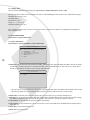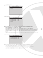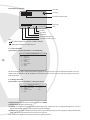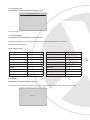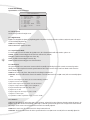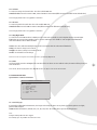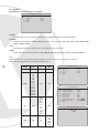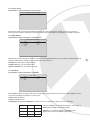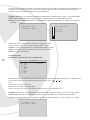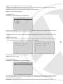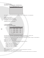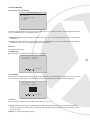
1
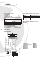
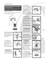
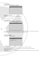
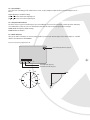
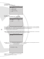
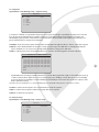
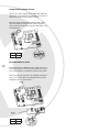
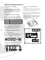
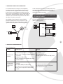
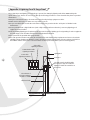
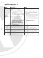
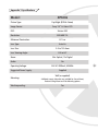
Model:
XPS036
True Day/Night 550/600 TVL Speed
Dome CCTV Camera with 36x Zoom
PLEASE READ THIS MANUAL BEFORE YOU INSTALL OR START USING THE XPS036 SPEED DOME
This equipment generates, uses, and can radiate radio frequency energy and, if not installed and used in accordance with the
instruction manual, may cause harmful interference to radio communications. Operation of this equipment in a residential area is
likely to cause harmful interference in which case the user will be required to correct the interference at the user’s own expense.
PRECAUTIONS:
zz Only qualified and experienced person can carry out the installation. In many countries and areas licensed personnel is required
zz Always take safety codes into consideration during installation.
zz Use reliable tools only, poor quality tools may cause damage to both human and property
zz Check the strength of all item onsite that are related to installation in advance. It is recommended that the stand of dome be at
least 4 times stronger than the weight of the dome and its accessories.
zz Keep all the original dome package materials in case of future repacking and transportation.
zz Choose and install speed dome according to environment requirement (Refer to the Product Features).
WARNINGS:
zz Avoid installing this speed dome in hazardous places where inflammable or explosive materials are stored or used.
zz Indoor dome is not designed for outdoor environment.
zz This speed dome runs on 24V AC.
zz Connect to power only after completing installation.
zz Disassemble can only be carried out by qualified personnel.
zz Use soft towel to clean the down cover when necessary. Avoid using caustic detergent.
zz Avoid aiming camera to strong light.
Model:
XPS036
True Day/Night 550/600 TVL Speed
Dome CCTV Camera with 36x Zoom
INDEX
2
1
PRODUCT DESCRIPTION
3
5.5
Camera Parameters
15
2
FEATURES
3
5.5.1
Sensetivity
15
3
INSTALLATION
4
5.5.2 AE Mode
16
3.1
Installation Preparation
4
5.5.3 Preset Freeze
17
3.1.1 Cables
4
5.5.4 White Balance
17
3.1.2 DIP Switches & Jumper settings
4
5.5.5 BLC Mode
17
3.1.3 Wiring Diagram
4
5.5.6
Video Phase
18
3.2
Wall Mounting Guide
5
5.5.7
Focus Min. Limit
18
4
SYSTEM CONNECTION
6
5.6
Pan/Tilt Parameters
18
5
OPERATING INSTRUCTIONS
7
5.6.1
Auto Stop Time
18
5.1
System Menu
7
5.6.2 Speed Adjust
19
5.1.1 System Menu Tree
8
5.6.3 PT Direction
19
5.2
9
5.6.4 North Direction
19
5.2.1 Selecting Values
9
5.7
Auto Running
20
5.2.2 Changing Values
9
5.7.1
Preset Setup
20
5.2.3 Editing Titles
10
5.7.2
Sequence
21
5.3
10
5.7.3
Pattern Setup
21
5.3.1 Dome Information
10
5.7.4
Panning Setup
22
5.3.2 Display Information
11
5.7.5
Region Setup
23
5.3.3 Init Information
12
5.7.6
Idle Time Setup
23
5.3.4 Change Password
12
5.7.7
Auto Action Setup
24
5.3.5 Language Select
13
5.8
Timer Running Setup
24
5.3.6 Factory Default
13
5.9
Privacy Masking
25
5.3.7 Restart
13
5.10
Alarm Setup
26
5.4
14
A1
APPENDIX I: DIP SWITCH & JUMPER
27
5.4.1 Zoom Speed
14
A2
5.4.2 Digital Zoom
14
5.4.3 Joystick Auto Mode
APPENDIX 2: WIRE DIAMETER
& TRANSMISSION DISTANCE
COMPARISON CHART
14
33
5.4.4 Auto Focus
14
APPENDIX 3: RS485 BUS
BASIC KNOWLEDGE
34
5.4.5 Auto Iris
14
5.4.6 Iris ALC
15
APPENDIX 4: LIGHTNING
PROOF & SURGE PROOF
36
5.4.7 Iris PLC
15
5.4.8 Day/Night Mode
15
APPENDIX 5: THE CLEANING
OF THE DOME COVER
37
5.4.9 Time
15
A6
APPENDIX 6: TROUBLESHOOTING
38
A7
APPENDIX 6: SPECIFICATIONS
39
Menu Operation
System Information
Lens Parameters
A3
A4
A5
1. Product Description
The XPS036 is a Professional True Day/Night Speed Dome with 36x Zoom with Mechanical IR Filter (making it IR sensitive for
use with Infra Red lighting). This camera is designed for use in very high risk applications where very high quality surveillance
is required and features an Xvision Auto Iris Zoom Lens with Auto Focus and 432x Zoom (36x Optical + 12x Digital) for easy
selection of any viewing angle between 0.5 and 64°. It can be panned, tilted and zoomed in seconds to the view required.
It is ideal for covering large areas and for viewing objects that are far away from the camera or for viewing moving objects that
are at varying distances from the camera thanks to its 36x zoom and auto focus function. The camera has an RS485 connection
allowing the Pan, Tilt, Zoom, Focus and On Screen Display set up of its features to be controlled remotely by any DVR or
Controller that supports Pelco D/P. It is weatherproof allowing it to be used internally or externally.
A variety of brackets are available for the camera depending on how and where you wish to mount it. Mounting options include
Wall Mount (as supplied), Pendant Mount on a Ceiling, Corner and Pole Mount (additional brackets required).
2. Features
zz True Day/Night Camera
zz Offers High Resolution 550/600 TVL images
zz Sleek design for professional applications
zz Cable Managed Bracket
zz Hi-accuracy motor drives with 0.1 degree preset accuracy, min. 0.1 degree moving without any vibration.
zz 360 degree continuous panning, 90 degree tilt with auto flipping.
zz Built in DSP camera, with auto focus, auto BLC, auto light control, auto white balance etc. functions.
zz Timer runing with up to 8 scheduled functions.
zz 220 presets, 4 sequences with up to 32 presets each
zz Supports up to 4 patterns of a minimum of 180 seconds each, 4 pannings, 8 regions, 8 privacy masks which can be set to
specific requirements
zz Features Auto Running for when the system is idle
zz Multiple RS485 protocols
zz Supports VCL, PELCO-P, PELCO-D, PELCO-C, PHILIPS, VICON, KALATEL, AMERICAN DYNAMICS, MOLYNX, PANASONIC
protocols.
zz On-Screen Display Menu for Programmable Functions and features an on screen compass and pan/tilt degrees indicator.
zz OSD Menu can be customized to suit user
zz Dome, preset, pattern, panning and region titles can be set to not display, display or display for a period of time.
zz Backup Memory for keeping user configurations after restarting dome
zz Designed for external wall mounting as supplied
zz Pole Mount, Pendant Ceiling Mount and Corner Mount brackets also available.
3
3. Installation
3.1 Installation Preparation
You may need the following tools for the installation:
Screws and nuts, screw driver, Small slotted screw driver, Wire cutter, Ladder, Drill, Saw.
3.1.1 Cables
zz Video Coaxial Cable
The video coaxial cable should be:
1) 75 Ohm impedance.
2) Solid copper wire.
3) 95% braided copper shield.
Check the max transmission distance referring to the chart
below:
4
INTERNATIONAL GAUGE
TRANSMISSION DISTANCE( MAX.)
RG 59/U
750ft (229m)
RG 6/U
1,000ft (305m)
RG 16/U
1,500ft (457m)
zz RS485 (Data) Cable
0.56mm (24AWG) twisted pair ’s maximum transmission
distances are as follows:
BAUD RATE
TRANSMISSION DISTANCE (MAX.)
2400bps
5,906ft (1800m)
4800bps
3,937ft (1200m)
9600bps
2,625ft (800m)
NOTE: Use RS485 distributor if you need to transmit
further. To learn more about RS485, please refer to
Appendix III.
3.1.2 DIP Switch & Jumper settings
Please refer to Appendix I to set the following:
zz Protocol & Baud rate
zz Alarm output method
zz Dome address
zz RS485 termination
resistor
zz Video cable type
3.1.3 Wiring Diagram
1
2
3
4
5
6
7
8
9
10
11
12
13
14
15
22
23
1. Alarm Input1
2. Alarm Input2
3. Alarm Input3
4. Alarm Input4
5. Alarm Input5
6. Alarm Input6
7. Alarm Input7
8. Alarm Input Common Port
9. Alarm Output1
10.Alarm Output1
11.Alarm Output2
12.Alarm Output2
16
17
18
19
20
21
13.Power - (Black)
14.Not Used
15.Power + (Red) 24V AC
16.Video Output
17.Video Ground
18.RS485 +
19.RS485 20.Not Used
21.Not Used
22.Not Used
23.Not Used
3.2 Wall Mounting Guide
ADDITIONAL MOUNTING BRACKETS ARE AVAILABLE
FOR CORNER MOUNT, PENDANT CEILING MOUNT AND
POLE MOUNTING OPTIONS.
REFER TO THE MANUAL SUPPLIED WITH THE BRACKETS FOR FURTHER
CORNER, CEILING OR POLE MOUNTING INSTRUCTIONS.
Installation Requirements:
The wall mounting surface must be firm enough to bear 4
times the weight of the speed dome.
4.Install housing
Insert cables through the
hole at the top of the housing
Apply water-proof tape to the
housing thread. Screw the
housing to the wall mount
adaptor with an M4 screw.
NOTE: Apply silicone to the
gap between bracket and wall
in the case of outdoor dome.
5. Connect cables
Connect the cables to the
power board. Swing the
power board holder back and
turn on the power. The red
LED will light up. Turn off the
power after checking.
NOTE: There are signs for
each port. Please connect
cables as picture shown.
Please MAKE SURE power is
off before connecting cables.
1. Mark screws positions
Take the bracket base as the
template to mark the screws
positions on wall. Drill the
holes and put expansion
screws inside.
2.Install bracket
Put Power/RS485/Video
cables through the cavity
of bracket, and then install
bracket on wall.
NOTE: Put cables through the
wall or aside the bracket.
3.Loosen the bolt and
swing away the
power board holder.
Loosen the bolt and swing
away the power board holder.
6.Set dome ID, baud
rate and protocol
Set dome ID, baud rate and
protocol via DIP switches
Remove the two sponges.
7. Fix Safety Chain
Attach the safety chain with
an M3 screw to prevent the
down cover from dropping.
8.Install black liner and
Pan/Tilt Module
Push the black liner into the
two locking tabs. Align the
pan/tilt module to the two
clips, red to red, black to
black align the holes & push
the module upward until you
hear two click sounds.
NOTE: Be sure the AMP
sockets are clean. DO NOT
forget to remove the lens cover.
9. Install down cover
Loosen the two M4 screws on
the cover ring. Apply lubricant
to the O-ring to make it easier
to slip in. Push upward the
down cover into the housing
and then fasten down.
5
4. System Connection
6
5. Operating Instructions
Two methods are available for carrying out the operation by the system controller.
1. Press the combined hot keys to operate different functions. Refer to the system controller manual for the detailed commands.
2.Access the OSD menu and operate according to the following instructions.
INITIAL INFORMATION
When you power up or restart the dome, the initial information below will display on screen when the dome is conducting selftesting. The information will disappear after the dome receives the first effective command.
Dome S/N
Dome ID
Baudrate
Protocol
Model:
Version
Pan Speed
Temp
H-Check
V-Check
Camera
Ready
:0000000000000000
:0001<Hard>
:4800
:FACTORY
:
: 1.00
:6500
:037C
:Pass
:Pass
:Pass
Dome S/N: The dome’s serial number
Dome ID: The dome ID address set by DIP switch or keyboard.
Baudrate: Baud rate for dome control bus.
Protocol: The dome’s controlling protocol. (please refer to Appendix I for more details)
Model: The dome model number.
Fan Speed: The speed of current running fan calculated by rounds per minute.
Temp: The dome inside temperature. Unit C or F
5.1 SYSTEM MENU
zz Access the dome’s main system menu on your monitor by calling preset 95 once or calling preset 1 twice within 5 seconds.
Note: The way to call a preset may vary among keyboards from different manufactures. Please read those manuals to learn keyboard
operation.
zz When there is password protection, user needs to input the correct 6-bit password to access the OSD menu. (Original
password is 000000).
zz To input password, move the joystick up or down to select number (0-9), move the joystick left or right to choose password
digit. If the input password is wrong, the password input window will close.
Note: You still can control the dome with a wrong password, but can not access to the OSD menu.
System Menu
1.
2.
3.
4.
5.
6.
7.
8.
0.
System Information
Lens Parameters
Camera Parameters
Pan/Tilt Parameters
Auto Running Setup
Timer Running Setup
Privacy Masking
Alarm Setup
Exit
The opened menu will disappear automatically without receiving any operation command in 1 minute. All the settings will be
saved automatically to protect against power cuts.
7
5.1.1 Menu Tree
System Information
1.
2.
3.
4.
5.
6.
7.
0.
Dome Information
Disp Information
Init Information
Change Password
Language Select
Factory Default
Restart
Exit
Lens Parameters
1. Zoom Speed
:High
2. Digital Zoom :Off
3. Joystick Auto :Both
4. Auto Focus
:5s
5. Auto Iris
:5s
6. Iris ALC
:084
7. Iris PLC
:016
8. Day Might Mode:Auto
9. Time : 00:00 00:00
0.Back
Camera Parameters
1. Sensitivity Up
2. AE Mode
3. Preset Freeze
4. White Balance
5. BLC Mode
6. Video Phase
7. Focus Min Limit
0.Back
Pan/Tilt Parameters
System Menu
8
1.
2.
3.
4.
5.
6.
7.
8.
0.
System Information
Lens Parameters
Camera Parameters
Pan/Tilt Parameters
Auto Running Setup
Timer Running Setup
Privacy Masking
Alarm Setup
Exit
1.
2.
3.
4.
0.
Auto Stop Time
:Off
Speed Adjust
:x1
Proportion Direction PT :On
North Direction
Back
1.
2.
3.
4.
5.
6.
7.
0.
Preset Setup
Sequence
Pattern Setup
Panning Setup
Region Setup
Idle Time Setup
Auto Action Setup
Back
Auto Running Setup
Timer Running Setup
Schedule Start
1
00:00
2
00:00
3
00:00
4
00:00
5
00:00
6
00:00
7
00:00
8
00:00
0. Back
End
00:00
00:00
00:00
00:00
00:00
00:00
00:00
00:00
Running
Off
Off
Off
Off
Off
Off
Off
Off
Privacy Masking
1.
2.
3.
4.
0.
Mask No
Setting
Activate Delete
Back
1.
2.
3.
4.
5.
6.
7.
8.
9.
0.
Alarm Input
Alarm Mode
Set Alarm
Input State
Run Function
Alarm Output
Reset Delay
Arm Type
DisArm Time
Back
:1
Empty
Alarm Setup
:1
:Manual
:ArmOff
:NC
:Off
:Off
:1s
:00:00
:00:00
5.2 Menu Operation
5.2.1 Selecting Items
In the main menu, the cursor flashes on the left, move the joystick up or down to move the cursor to the desired setting item.
Move the joystick to the right to select the item.
Select an item to:
1. Access its sub-menu
2.Run a specific function
3.Change its value or edit its title.
5.2.2 Changing Values
Move the joystick up or down to change the value, move the joystick to the left to save the setting and to exit. In the case of
more than one value, move the joystick left or right to select place, move up or down to change value. Move the joystick to the
leftmost to save the setting and to exit.
Note: To increase the value changing speed, hold the joystick in up or down position for more than 10 seconds.
For example: In order to change the password, please follow these steps.
1. Call preset 95 or call preset 1 twice within 5 seconds to access to the main menu.
2.Move the joystick down to let the cursor point to System Information then move the joystick to the right to select it.
System Menu
1.
2.
3.
4.
5.
6.
7.
8.
0.
System Information
Lens Parameters
Camera Parameters
Pan/Tilt Parameters
Auto Running Setup
Timer Running Setup
Privacy Masking
Alarm Setup
Exit
3.Move the joystick down to let the cursor point to Change Password then move the joystick to the right to select it.
Note: Here-in-after menu paths are written in the following format: Main menu > System Information >Change Password
System Information
1.
2.
3.
4.
5.
6.
7.
0.
Dome Information
Disp Information
Init Information
Change Password
Language Select
Factory Default
Restart
Exit
4.Input the old password and new password, Default password is 000000. Move joystick left or right to set a digit; Move up or
down to change a number. Move cursor to leftmost index position after inputting a new password
Select “3. Confirm” to confirm the new password. The system will indicate “Old Password error” or “ Pwd Modify Success”.
Change Password
1.
2.
3.
4.
0.
Input Old Pwd
Input New Pwd
Confirm
Pwd Protect
Back
: ******
: ******
: Off
9
5.2.3 Editing Titles
Access Dome Title Edit Menu following the path: System menu > Dome Information > Title > Input
Move the cursor left or right to select a character, move down to edit the blinking character. Zoom In/out to switch character groups:
zz Number [0 1 2 3 4 5 6 7 8 9 ]
zz Capital [A B C ]
zz Lowercase [a b c ]
zz Sign [ / + - ( ) & % # ! $ ]
zz Special characters [ á í ó w é ]
Move to desired character, then move up to select or move down to cancel. Note: Call preset 1 to switch between Modify and
Insert editting method.
5.3 System Information
System menu > System Information
5.3.1 Dome Information
System Menu > System Information > Dome Information
Dome Information
1.
2.
3.
4.
5.
6.
0.
Dome ID : 001
Dome Title: 0000000000000000
Broadcast : 255
SystemDate: 09-05-31
SystemTime: 10:17:12
Temp Unit :C
Back
10
zz Dome ID: Dome ID shows the current dome’s ID number. Each dome has its unique ID ranging from 001 to 255 (255 is default
broadcast ID ). The Dome ID can be set only when DIP switch is in Programmable ID mode. Move the cursor to Dome ID and
then move the joystick to the right to access dome ID setting submenu:
S/N 2529647106
1. Input
2. Back
: 0000000000
-- Move the cursor to Input and then move the joystick to the right, input the S/N in accordance with the number above the line.
-- Move the joystick up or down to change the value and then move the joystick to the left to save the setting.
zz Dome Title: It is the title of the dome. Assigning a name to a dome helps user to remember which dome it is.
zz Broadcast: It sets broadcast. ID number (001~255). The ID number should be different from any other dome, default setting is
255. When a command is sent to broadcast ID, all the domes connected to the control bus accept the command.
zz System Date: Set the System Date. Display format is year-month-day.
zz System Time: Set the system time in order to show the time on screen and enable timer scheduled functions. Display format:
hour : min : sec
zz Temp Unit: Select temperature unit C or F
zz Back: Return to previous menu.
5.3.2 Display Information
System Menu > System Information > Display Information
Display Configuration
1. Title Information
2. Other Information
0. Back
zz Title Information
Title Information
1.
2.
3.
4.
5.
0.
Dome Title
Preset Title
Pattern Title
Panning Title
Region Title
Back
:
:
:
:
:
Off
Off
Off
Off
Off
This sub-menu allows user to select either display some information on screen or not. Information includes:
-- Dome Title (ON/OFF): To set whether display dome title.
-- Preset Title (ON, OFF, 3s-255s): To set ON or OFF or display time for preset title when calling preset.
-- Pattern Title (ON, OFF, 3s-255s): To set ON or OFF or display time for pattern title when the dome is replaying pattern.
-- Panning Title (ON, OFF, 3s-255s): To set ON or OFF or display time for panning title when the dome is performing a
panning.
-- Region Title (ON, OFF, 3s-255s): To set ON or OFF or display time for region title when the camera moves to the region.
zz Other Information
Other Information
1.
2.
3.
4.
0.
Zoom Times Infor :
Direction Infor :
AlarmState Inform:
Dome Clock Infor :
Back
Off
Off
Off
Off
This sub-menu allows user to select either display some information on screen or not. Information includes:
-- Zoom Times Infor (ON, OFF, 3s-255s): To set ON or OFF or the display time of the zoom times.
-- Direction Infor (ON, OFF, 3s-255s): To set ON or OFF or the display time of camera pointing direction.
-- Alarm State Infor (ON/OFF): To set whether display the alarm state information
-- Dome Clock Infor (ON/OFF): To set whether display the system time.
11
Information text Position
Dome Title
Pan degree
Preset/Pattern/Panning Title
Region Title
P134 T74
XX
2X
16.25.06
Time
Fan Alert
Zoom Times
Alarm Alert
Vertical Tilt Value (degrees)
Horizontal Pan Value (degrees)
Note:
Fan symbol indicates fan speed below 1000 rounds/min.
Alarm symbol indicates an alarm comes in.
5.3.3 Init Information
System Menu > System Information > Init Information
Init Information
12
1.
2.
3.
4.
5.
6.
7.
8.
0.
Dome S/N
Dome ID
Baudrate
Protocol
Model
Version
Fan Speed
Temp
Back
This menu shows the dome’s summary information, helping user to know the dome’s states. Information includes: Dome S/N
number, Dome ID (hard ID or soft ID), BaudRate, Protocol, Dome model, Software version, Fan speed (rounds per min), Dome
inside temperature.
5.3.4 Change Password
System Menu > System Information > Change Password
Change Password
1.
2.
3.
4.
0.
Input Old Pwd
Input New Pwd
Confirm
Pwd Protect
Back
: ******
: ******
: Off
zz Old password: Input old password, Default password is 000000.
zz New password: Input new password.
zz Confirm: To confirm the password changing. System will pop-up “old password error” if old password input is not correct,or
pop-up “Pwd modify success” to indicate password has been changed.
zz Pwd protect: To enable or disable password protection. System will request password to change this setting. If Pwd Protect
is ON, user needs to input password to access menu or set preset.
Note: Contact your supplier for master password if you forget the password.
5.3.5 Language Select
System Menu > System Information > Language Select
Language Select
Language : English
Select one language.
5.3.6 Factory Default
System Menu > System Information > Factory Default
Select Factory Default to restore factory default settings. System will request password to set it. Factory
default will not change dome ID.
List of Default Settings
Zooming Speed
HIGH
White Balance
Auto
Digital Zoom
x10
Focus Min Limit
30cm
Joystick Auto
Both
Idle Tune
30S
Auto Focus
5S
Auto Action
Off
Auto Iris
5S
Alarm Mode
Manual
Iris ALC
084
Set Alarm
Armoff
Iris PLC
016
Input State
NC
Day Night Mode
Auto
Run Function
Off
Sensitivity
1/1.5
Alarm Output
Off
Preset Freeze
Off
Reset Delay
20S
5.3.7 Restart
System Menu > System Information > Restart
Select Restart to reboot the dome. Then the pop-up window appears as below. Settings will not change after restarting.
Restart...
13
5.4 Lens Parameters
System Menu > Lens Parameters
Lens Parameters
1.
2.
3.
4.
5.
6.
7.
8.
9.
0.
Zoom Speed
Digital Zoom
Joystick Auto
Auto Focus
Auto Iris
Iris ALC
Iris PLC
Day Might Mode
Time : 00:00
Back
:High
:Off
:Both
:5s
:5s
:084
:016
:Auto
00:00
5.4.1 Zoom Speed
Set the zoom speed level to High or Low.
5.4.2 Digital Zoom
Digital zoom magnifies the picture by duplicating pixels. The picture is enlarged but the resolution remains the same. This menu
sets the maximum digital zoom.
zz OFF: Turn off digital zoom
zz X1 to X12: Max. digital zoom times
14
5.4.3 Joystick Auto Mode
To set automatic restore mode. When the joystick moves, the selected function will start. Function options are:
zz Both: Joystick movement triggers both auto focus and auto iris. (default)
zz Focus: Joystick movement triggers auto focus only.
zz Iris: Joystick movement triggers auto iris only.
zz Off: Joystick movement triggers none of the functions.
5.4.4 Auto Focus
The system default is set to Auto Focus. Focus can also be manually controlled by key board or matrix. For manual operation
details, please refer to keyboard or matrix operation manual. The setup is used to restore auto focus function after focus has
been manually adjusted.
zz OFF: Never restore auto focus. That means focus is always in manual mode
zz 001-255: The dome will start auto focus in the number of seconds that have been set (001 to 255) after user manually adjusts
focus.
Note: The camera might not be able to auto focus in the following conditions:
1) Target is not in the centre of image.
2) Near and far targets in the same picture can not be both clear.
3) Target is an object with strong light, such as spotlight etc.
4) Target is behind the glass with water drop or dust.
5) Target moves too fast.
6) Target is supposed to be a large area such as a wall.
7) Target is too dark or vague.
8) Joystick Auto set Off or Joystick Auto set Iris, or Focus is set OFF.
5.4.5 Auto Iris
Light passes through the iris and reaches CCD to form an image. A larger iris lets more light pass through causing the image to be
brighter. Iris can be controlled automatically or manually. For manual operation detail, please refer to keyboard or matrix manual.
The setup is used to restore auto Iris function after Iris has been manually adjusted.
zz OFF: Never restore auto iris. That means iris is always in manual mode.
zz 001-255: The dome will start auto iris in the speed that have been set (001 to 255 seconds) after user manually adjusts iris.
5.4.6 Iris ALC
To set the iris average level control value. The value could be 000~255.
zz Default value: 22X Colour Camera: 066, 23X Colour/Mono camera: 084 (different camera has different ALC default value)
Note: Changing default value is strongly NOT recommended.
5.4.7 Iris PLC
To set the iris peak level control value. The value could be 000~127.
zz Default value: 23X Colour/Mono camera: 016 (different camera has different PLC default value)
Note: Changing default value is strongly NOT recommended.
5.4.8 Day/Night Mode
To set the dome Colour/Monochrome switching mode. Colour mode is suitable to work in daytime because it needs higher
illumination. By contrast, light sensitivity of mono mode is much higher. It is suitable to work at night in low illumination
environment but the video is black and white.
zz Auto: The dome will automatically change modes in accordance with the environment illumination.
zz Day: The dome is always in colour mode.
zz Night: The dome is always in monochrome mode.
zz Time: Set schedule for mode change.
Note: You need to set exposure mode to Auto in order to get Auto Day/Night mode
5.4.9 Time
Set the Day Mode start time and Night mode start time. If the two times are same with the other, the camera will stay in current
mode all the time.
Note: Iris PLC, IRF Control, Day Mode Time, Night Mode Time can only be set in certain camera models.
5.5 Camera Parameters
System Menu > Camera Parameters
Camera Parameters
1.
2.
3.
4.
5.
6.
7.
0.
Sensitivity Up
AE Mode
Preset Freeze
White Balance
BLC Mode
Video Phase
Focus Min Limit
Back
5.5.1 Sensitivity Up
In extremely low illumination circumstance, the images retrieved by the dome are very dark. Slow shutter gathers more light,
pictures will be brighter.
zz OFF: Disable this function. (default) 1/1.5, 1/3, 1/6, 1/12, 1/25: The smaller value represents brighter pictures.
Note:
zz High sensitivity will make video sluggish.
zz Sensitivity up is only available when AE mode is Auto.
15
5.5.2 AE Mode
System Menu > Camera Parameters > AE Mode
Exposure Mode
1.
2.
3.
4.
0.
Mode
Shutter
Iris
AGC
Back
:Auto
:N/A
:N/A
:N/A
zz Mode
-- The value options are: Auto, Shutter, Iris and AGC. The setting will take priority overall other settings.
zz Shutter
-- Set Shutter speed as priority, available: settings are 1/1.5, 1/3, 1/6, 1/12, 1/25, 1/100, 1/150, 1/250, 1/500, 1/1000, 1/2000,
1/4000, 1/10000, 1/30000
zz Iris
-- Set Iris as priority. Values are: F1.6, F2.2, F3.2, F4.4, F6.4, F8.8, F12, F17, F24, F34
zz AGC
-- Set Auto gain control as priority. Values are: 0dB, 6dB,12dB,18dB,24dB,30dB. Higher dB value makes image brighter.
Note:
zz Day/Night Auto mode and Sensitivity Up will be void if Exposure mode is not Auto mode. See example screens below.
zz Only one of settings for Shutter, Iris and AGC will take effect
16
MODE
Shutter
Iris
Auto
N/A
N/A
N/A
Shutter
1/1.5,
1/3,
1/6,
1/12,
1/25,
1/100,
1/150,
1/250,
1/500,
1/1000,
1/2000,
1/4000,
1/10000,
1/30000
N/A
N/A
N/A
F1.6,
F2.2,
F3.2,
F4.4,
F6.4,
F8.8,
F12,
F17,
F24,
F34
N/A
N/A
0dB,
6dB,
12dB,
18dB,
24dB,
30dB.
Iris
AGC
N/A
Exposure Mode
AGC
1.
2.
3.
4.
0.
Mode
Shutter
Iris
AGC
Back
1.
2.
3.
4.
5.
6.
7.
8.
9.
0.
Zoom Speed
Digital Zoom
Joystick Auto
Auto Focus
Auto Iris
Iris ALC
Iris PLC
Day Might Mode
Time : 00:00
Back
:Shutter
:1/50
:N/A
:N/A
Lens Parameters
:High
:Off
:Both
:5s
:5s
:084
:016
:Auto N/A
00:00
Sensitivity Up
Sensitivity Up N/A
5.5.3 Present Freeze
System Menu > Camera Parameters > Preset Freeze
Preset Freeze Setup
Preset Freeze: Off
If Preset Freeze is On, the current image will freeze until the image of the preset presents. Therefore you can not see the scene
between the current position and the preset. This feature reduces useless data traffic in web application & save DVR storage space.
5.5.4 White Balance
System Menu > Camera Parameters > White Balance
White Balance Mode
1.
2.
3.
0.
Mode
R Gain
B Gain
Back
:Auto
:N/A
:N/A
White balance simulates sun light circumstance. However in certain lighting conditions, user may want to manually adjust the red
(R Gain) and blue (B Gain) settings for optimal viewing. The value options are:
zz AUTO: Auto white balance. (default setting)
zz USER: Manually set the red and blue values.
zz R Gain & B Gain Set: red and blue color depth.
5.5.5 BLC Mode
System Menu > Camera Parameters > BLC Mode
BLC Mode
1. Mode
2. BLC
0. Back
:Off
:N/A
If the backlight is bright, the objects in the centre of the picture may appear dark. The dome can auto adjust the brightness of the
whole image according to the brightness of centre point.
zz OFF: Disable the function.
zz BLC: Standard BLC mode.
zz WDR (Does not appear on OSD Menu): Call preset 62 to set as “WDR ON”, Call preset 63 to the “WDR OFF”
MODE
BLC
WDR
Off
N/A
N/A
BLC
000~255
N/A
WDR
N/A
000~128
When the backlight mode is setting in BLC Mode, set the values as:
-- 000: Disables backlight compensation function.
-- 001-255: Choose different backlight compensation grade.
Higher value means more backlight compensation.
17
5.5.6 Video Phase
System Menu > Camera Parameters > Video Phase
Video Phase
Phase
: Off
zz OFF: Disable this function.
zz 001~360: Choose the suitable phase to get synchronous video.
Note: Some models only have ON/OFF.
5.5.7 Focus Min Limit
System Menu > Camera Parameters > Focus Min Limit
Video Phase
Focus Limit
: 30cm
18
Set a minimum distance from the lens, the camera will not focus on objects in that distance. E.g. This feature can prevent camera
from focusing on the down cover. Values for focus limit are: 1cm, 10cm, 30cm, 100cm
5.6 Pan/Tilt Parameters
System Menu > Pan/Tilt Parameters
Pan/Tilt Parameters
1.
2.
3.
4.
0.
Auto Stop Time
:Off
Speed Adjust
:x1
Proportion Direction PT :On
North Direction
Back
5.6.1 Auto Stop Time
For some particular protocols, the dome will not stop moving even there is no operation on controller.
This menu item sets the time that, after a specified time period, the dome will stop itself. Values are in 50ms unit:
zz OFF: Disable this function (default setting)
zz 001~255: After value x 50ms the dome will automatically stop moving. For example: 003 means the dome will automatically
stop moving after 150ms.
5.6.2 Speed Adjust
Some protocols’ controlling speed is either faster or slower, set Speed Adjust to adjust the dome movement. Options are as
below:
zz X1: Original speed (default setting)
zz 2 ~ 32: Times faster than original speed.
zz 2 ~ 32: Times slower than original speed.
5.6.3 Proportion Direction PT
The dome moves at a speed of certain degrees per second. Objects on screen move much faster in telescope than in widescope,
even undesirable too faster in some case. This function decreases the dome movement speed while zooming in.
zz ON: Enable the function (default setting)
zz OFF: Disable the function
5.6.4 North Direction
User can set dome’s orientation on screen by using joystick to position north. The Pan degree is the relative degree to a specific
direction. That direction is called NORTH.
Note: Not restricted to geographical north.
Horizontal Angle indicator (degrees)
19
P134 T74
XX
2X
Vertical Tilt Value (degrees)
Horizontal Pan Value (degrees)
N
30°
90°
60°
W
E
120°
S
0
5.7 Auto Running
System Menu > Auto Running Setup
Auto Running Setup
1.
2.
3.
4.
5.
6.
7.
0.
Preset Setup
Sequence
Pattern Setup
Panning Setup
Region Setup
Idle Time Setup
Auto Action Setup
Back
5.7.1 Preset Setup
System Menu > Auto Running Setup > Preset Setup
Preset Setup
1.
2.
3.
4:
0.
20
Title Setting
Show
Delete
Back
:Preset001
:001
:001
:001
Preset is the point that user saves for frequent use. A preset saves both direction and zoom parameters, the camera will quickly
and precisely go and zoom to a specific point if a preset is called. e.g. If you often want to see the door, you can set the point of
door as preset P, then you can see the door simply by calling the preset P. This dome has 220 presets.
Note: preset 95 is reserved for accessing dome menu.
zz Title: To set the preset title. Move the joystick left or right to select the target letter, Turn joystick clockwise or anti-clockwise
to select input method. Move up or down to select the desired letter, number or character.
Preset Title Edit
1. Input 0. Back
:Preset001
zz Setting: Select a preset number then move right. The following menu will display. Move to the desired position and zoom to
a suitable level, call preset 1 to save the current preset, call preset 2 to cancel.
Call Preset 1 Save
call Preset 2 Cancel
zz Show: Select a preset number and show the preset position.
zz Delete: Select a preset number and delete.
5.7.2 Sequence
System Menu > Auto Running Setup > Sequence Setup
Sequence
1.
2.
3.
4:
5.
6.
0.
Number
Dwell
Edit
Show
Run
Delete
Back
:001
:003
A “sequence” is defined as a sequencial moving from preset to preset and dwell for a specific time at each preset. It is useful
if you need to repeat switching among a number of presets. E.g. A shopping mall has several entrances. A sequence can
automatically loop the position of each entrance. 4 sequences can be set for the dome. Each sequence can contain up to 32
presets and dwell time for each preset is independent.
zz Number: Shows the current sequence number. Values are 001~004. Pan right then tilt up or down to select other sequence.
zz Dwell: Sets the default dwell time in seconds for each preset. Value ranges from 000~255. For example, Dwell: 001, all
presets’ dwell time is 1 second, user can set independent dwell time for each preset in Edit menu.
zz Edit: To edit the presets and corresponding dwell time in a Sequence. The following picture shows the edit menu.
[Preset No - Dwell Time]
[001-006][002-004][003-002][003-002]
[000-002][000-002][000-002][000-002]
[000-002][000-002][000-002][000-002]
[000-002][000-002][000-002][000-002]
[000-002][000-002][000-002][000-002]
[000-002][000-002][000-002][000-002]
[000-002][000-002][000-002][000-002]
[000-002][000-002][000-002][000-002]
Save
Back
E.g. 003-002 means accessing preset 003 and dwell for 2 seconds. Move joystick left or right to select editing item, move up
or down to change value.In picture above, the tour starts from preset 1 dwelling 2 seconds, then goes to preset 2 dwelling
4 seconds, then preset 3 dwelling 2 seconds and finally preset 4 dwelling 1 second. Select Save to save the sequence, select
Back to quit without saving.
Note: When a preset’s dwell time is set 0, system will skip that preset. System will consider preset 0 as the end of a sequence.
zz Show: To run the current sequence once. Use this function to check the sequence.
zz Run: To run the current sequence continuously. System will loop the sequence.
zz Delete: To delete current sequence.
5.7.3 Pattern Setup
System Menu > Auto Running Setup > Pattern Setup
Pattern
1.
2.
3.
4:
5.
6.
0.
Number
Title
Record
Show
Run
Delete
Back
:001
:Pattern1
21
A pattern records a continuous movement of the camera in a period of time. The difference between sequence and pattern is that
in a sequence, dome moves from a preset to next at a fixed speed; in a pattern, dome moves flexible curve at various speed.
Speed Dome can record 4 patterns, minimum 180 seconds each pattern.
zz Number: Indicates the current pattern number. Values are 001~004. Pan right then tilt up or down to select another pattern
zz Title: Title is the title of the Pattern. Assigning a name to a Pattern helps user to remember which pattern it is.
zz Record: To start recording the pattern. The recording begins immediately after calling preset 1 or call preset 2 to cancel the
recording.
Call Preset 1 Start
Call Preset 2 Cancel
Call Preset 1 End
Pattern 01
[00:01:30]
Column on the left shows the time lapse and volume of the pattern memory.
Note: Pattern memory only records the operation of pan/tilt and lens command.
zz Show: To run the current pattern once. Use this function to check the pattern.
zz Run: To run the current pattern continuously. System will loop the pattern.
zz Delete: To delete current pattern.
22
5.7.4 Panning Setup
System Menu > Auto Running Setup > Panning Setup
Panning
1.
2.
3.
4:
5.
6.
7.
8.
0.
Number
Title
Start
End
Speed
Show
Run
Delete
Back
:001
:AutoPan1
Panning enables user to scan back and forth an area between two parallel sites(with same vertical degree) at a definable speed.
e.g. If two sites (A & B) are set, the camera will loop between the two sites: A B A B.
Notes:
zz Dome makes horizontal movement only.
zz This dome has a maximum of 4 Panning settings.
zz If the camera has been zoomed to a desired level then during panning, the camera will keep that zoom.
zz Number: Display the current panning number. Values are 001~004. Pan right then tilt up or down to select other panning.
zz Title: Designate the title of the panning. Assigning a name to a panning helps user to remember which panning it is.
zz Start: To set the start position. Move the camera to a particular position and call preset 1 to save or call preset 2 to cancel.
Call Preset 1 Save
Call Preset 2 Cancel
zz End: To set the ending position. Set it in the same way as Start.
zz Speed: Sets the panning speed (Dome movement speed). Value ranges from 001 to 255, the higher value represents the
higher speed. Pan right to select, tilt up or down to change value.
zz Show: To run the current panning once, use this function to check the panning
zz Run: To run the panning continuously.
5.7.5 Region Setup
System Menu > Auto Running Setup > Region Setup
Region Setup
1.
2.
3.
4:
5.
0.
Number
Title
Setup
State
Delete
Back
:001
:Region1
Empty
A region is an area between two sites. User can assign a title for a REGION. (E.g. Dangerous area). Whenever the camera moves
into the region, the title will display on the screen to alert the user.
zz Number: Displays the current region number. Values ranges from 001~008. Pan right then tilt up or down to select another
region.
zz Title: Set the region title.
zz Setup: Move to the desired position and call preset 1 to save left limit or call preset 2 to cancel. After setting the left limit,
below menu will pop-up, set the right limit as the same way as setting left limit
23
Call Preset 1 :Left Limit
Call Preset 2 Cancel
Call Preset 1 :Right Limit
Call Preset 2 Cancel
zz State: Indicate the current region is existing or empty
zz Delete: Delete current region.
5.7.6 Idle Time Setup
System Menu > Auto Running Setup > Idle Time Setup
Idle Time Setup
Idle Time
:30s
This function let the system automatically run assigned function after the idle time. For example: the dome is running a sequence
and an operator breaks the sequence to do other work, the dome can automatically carry on the sequence within a period of
time after the operator finishes using it.
zz Idle Time: It is a specific time without any operation being performed. The values include: Off, 003s~255s (seconds).
5.7.7 Auto Action Setup
System Menu > Auto Running Setup > Auto Action Setup
Auto Action Setup
Auto Action :Off
Auto action refers to the function that system will automatically run when idle time is out. Setting include:
zz OFF: Disable this function
zz Preset (1~220): Call preset 001~220
zz Panning (1~4): Run panning 001~004
zz Sequence (1~4): Run sequence 001~004
zz Pattern (1~4): Run pattern 001~004
5.8 Timer Running Setup
System Menu > Timer Running Setup
Timer Running Setup
Schedule Start
1
00:00
2
00:00
3
00:00
4
00:00
5
00:00
6
00:00
7
00:00
8
00:00
0. Back
24
End
00:00
00:00
00:00
00:00
00:00
00:00
00:00
00:00
Running
Off
Off
Off
Off
Off
Off
Off
Off
This function allows the system to run specified functions during the scheduled time. For example, let the
dome run a Pattern from 3 to 5 pm without any operator controlling the dome at that time.
zz Schedule: Display current time slot index number. 8 time slots are available. Move joystick to the right to set this schedule or
move up or down to select another time slot.
zz Start: Set the start time of Timer Running.
zz End: Set the stop time of Timer Running.
zz Running: Enable the timer running functions during the specified period of time.
-- OFF: Disable timer running function.
-- Preset (1~220): Enable Preset function.
-- Sequence (1~4): Enable Sequence function.
-- Pattern (1~4): Enable Pattern function.
-- Panning (1~4): Enable Panning function.
NOTE:
zz The specified time can not be overlapped otherwise, the assigned Timer Running functions are ineffective.
zz Timer Running function will take priority over Auto Action function.
zz Operations on keyboard will override the Timer Running function, however the function will continue after 10 seconds idle time.
5.9 Privacy Masking
System Menu > Privacy Masking
Privacy Masking
1.
2.
3.
4.
0.
Mask No
Setting
Activate Empty
Delete
Back
:1
The feature of privacy masking can be used to protect public privacy. e.g. a resident’s window, a toilet. Integrated Speed Dome
can cover a black square on some particular locations.
zz Mask No: Display the current masking zone number. Values are 1~8 or 1~4. Pan right then tilt up or down to select another
masking zone.
zz Setting: Select this menu item to set the position and size of the masking zone. There are two setting methods for different
model dome, please refer to your supplier which method your model is.
Method A
The setting has three steps:
1. Choose area
Move the camera to your desired area and call preset 1 to confirm.
Call Preset 1 :Position
Call Preset 2 :Cancel
Move Dome
2.Set position
Enter setting, the following window will pop up. Move the black square to the desired position, call preset 1 to save. Tip: Put the
top left corner of the black square on the desired position because the black square can expand down and right only.
Call Preset 1 :Size
Call Preset 2 :Cancel
Move Dome
3.Set size
Move the joystick to adjust the size of the black square, call preset 1 to save.
zz Activate: Enable / disable the current privacy masking. (ON: enable, OFF: disable) The zoom times for Privacy Masking
activation is effective for certain models only. When zoom times is higher than a specific value, the dome will auto activate
the privacy mask.
zz Delete : To delete current privacy masking.
25
Method B
The setting has two steps:
4.Choose area
Move the cross to the centre of desired position, call preset 1 to save the position then go to step 2 or call preset 2 to cancel.
Call Preset 1 :Save
Call Preset 2 :Cancel
Move Dome
5. Set size
Move up, down, left or right to adjust the size, call preset 1 to save or call preset 2 to cancel.
Note: One screen has limited number of privacy mask. If the masking number exceeds, system will pop up an alert message: ‘Position Error’.
User can choose other place or delete other masking to set a new one.
zz Activate: To indicate whether this privacy masking is existing or not. (Empty: Not set. Open: Existing)
zz Delete : To delete current privacy masking.
5.10 Alarm Setup
System Menu > Alarm Setup
Alarm Setup
26
1.
2.
3.
4.
5.
6.
7.
8.
9.
0.
Alarm Input
Alarm Mode
Set Alarm
Input State
Run Function
Alarm Output
Reset Delay
Arm Type
DisArm Time
Back
:1
:Manual
:ArmOff
:NC
:Off
:Off
:1s
:00:00
:00:00
zz Alarm Input: Select the number of alarm input channel (1-7).
zz Alarm Mode: Auto or manually set alarm.
-- Auto: Dome will set alarm based on Arm Time and DisArm time.
-- Manual: Manually set alarm in following item
zz Set Alarm: Arm off or Arm on.
-- Set Alarm: Arm off or Arm on (Disable or enable the alarm input channel)
zz Input State: Select current alarm input channel’s normal state. NO or NC ( normal open or normal close).
zz Run Function: Set auto respond function.
-- Off
-- Preset (001-220)
-- Panning (1-4)
-- Pattern (1-4)
-- Sequence (1-4)
zz Alarm Output: Select respond output channel for current input channel. Off, 1, 2, 1&2.
zz Reset Delay: Set the time that system will auto reset the alarm after current alarm inputs
-- Values: 1 second to 255 second.
zz Arm Time: Set the alarm enable time.
zz DisArm Time: Set the alarm disable time.
Note: It only takes effect when alarm mode is set auto.
Appendix I: DIP Switch & Jumper Settings
This appendix guides you to set protocol, baud rate, dome
address, video cable type, alarm output and resistor jumper.
This speed dome supports multi-protocol. The setting chart
is shown below, O means ON, blank means OFF, X means
either ON or OFF. Default setting is factory.
DIP SWITCHES’ POSITION
The corresponding DIP-switches’ positions are shown below:
Switch Number
Protocol
ON
1
2
3
4
5
6
7
8
FACTORY
VCL
PELCO_P
PELCO_D
MOLYNK
VICON
DIAMOND
KATATEL
Reserved
Reserved
Reserved
PELCO_C*
PROTOCOL AND BAUD RATE SETTING
SW2 is used to set protocol and baud rate. The first six (1-6)
bits of SW2 are for protocol setting and the last two (7-8)
bits are for baud rate setting. Below chart shows the setting
details. O means ON, blank means OFF. Default setting is
4800 bps.
Reserved
Reserved
27
Reserved
AD*
Reserved
PANASONIC
Reserved
Switch Number
Baud Rate
SENSORNET*
ON
Reserved
B8V*
1
2
3
4
5
6
7
8
2400bps
4800bps
Reserved
Reserved
Reserved
Reserved
9600bps
Reserved
19200bps
Reserved
Reserved
NOTE: If you are using AD or PHILIPS or BBV protocol, please set
the baud rate to 19200 bps.
Reserved
Reserved
Reserved
PHILIPS*
X
X
X
X
X
NOTE: Protocols marked with * need another protocol
board.
DOME ADDRESS SETTING
ADDRESS SETTING CHART
O means ON, blank means OFF.
The control commands contain target dome’s ID. The dome
only reacts to the command sent to its own address or
broadcast address. So, each dome should be assigned an
address. Four kinds of IDs are applicable for domes:
zz Hard ID: Hard ID is set via DIP SW1, it can not be
changed from OSD menu. Hard ID ranges from 1 to 255.
zz Programmable ID: Set all 8-bits of SW1 to ON to
activate programmable address. Input 10-bit camera SN
number, and then set dome ID by controller (The dome
SN number can be found on the side of the camera or on
the package.).
zz Debug ID: Set all the bites of the SW1 to 0 (all OFF), the
dome will react to any command for any ID.
Switch Number
ID
1
0
1
2
3
4
5
NOTE: Debug ID only works with Factory protocol.
6
zz Broadcast ID: When a command is sent to broadcast ID,
all domes connected to the control bus will respond to
that command. Broadcast ID is definable, ranges from 1
to 255, the default broadcast ID is 255.
7
SW1 is used for setting dome ID. The setting is strictly in
accordance with binary system, if you are not familiar with
binary system please look up the address setting chart.
8
9
10
11
12
13
14
28
NOTE: When using Philips protocol, the first 5 bits of SW2 and
all bits of SW1 are for address setting. Max address can be 8191.
Example: in order to set address 2657, set bit 1, 6, 7 of SW1 and bit
2, 4 of SW2 ON. (2657=1+32+64+512+2048)
ON
15
16
17
18
19
20
21
22
23
24
25
26
27
28
29
30
31
32
33
34
35
36
37
38
39
40
41
42
43
2
3
4
5
6
7
8
Switch Number
ID
Switch Number
ON
1
ID
2
3
4
5
6
7
8
ON
1
44
88
45
89
46
90
47
91
48
92
49
93
50
94
51
95
52
96
53
97
54
98
55
99
56
100
57
101
58
102
59
103
60
104
61
105
62
106
63
107
64
108
65
109
66
110
67
111
68
112
69
113
70
114
71
115
72
116
73
117
74
118
75
119
76
120
77
121
78
122
79
123
80
124
81
125
82
126
83
127
84
128
85
129
86
130
87
131
2
3
4
5
6
7
8
29
Switch Number
ID
ON
1
30
Switch Number
ID
2
3
4
5
6
7
8
ON
1
132
176
133
177
134
178
135
179
136
180
137
181
138
182
139
183
140
184
141
185
142
186
143
187
144
188
145
189
146
190
147
191
148
192
149
193
150
194
151
195
152
196
153
197
154
198
155
199
156
200
157
201
158
202
159
203
160
204
161
205
162
206
163
207
164
208
165
209
166
210
167
211
168
212
169
213
170
214
171
215
172
216
173
217
174
218
175
219
2
3
4
5
6
7
8
Switch Number
ID
ON
1
2
3
4
5
6
7
8
220
221
222
223
224
225
226
227
228
229
230
231
232
233
234
235
236
237
238
239
240
241
242
243
244
245
246
247
248
249
250
251
252
253
254
255
Programmable
Address
31
ALARM OUTPUT METHOD SETTING
There are two alarm output methods: NO and NC. NO means
normal state is open circuit, the circuit will be closed when an
alarm comes in. NC means normal close circuit.
When choosing pins 1&2 in JP6 and JP7,the alarm output
state is NC. When choosing pins 2&3 in JP6 and JP7, the
alarm output state is NO. Factory default is NO. (Refer to the
following picture):
12
23
NC
NO
RESISTOR JUMPER SETTING
32
RS485 bus needs two 120 Ohm resistors at both ends. Set on
the 120 Ohm resistors of the two devices (keyboard or dome)
in the farthest distance on RS485 bus. Default setting is OFF.
When connecting pins 1&2 in JP1, the 120 Ohms termination
resistor is connected. When connecting pins 2&3 in JP1, the
termination resistor is unconnected.
12
23
ON
OFF
Appendix 2: Wire Diameter & Transmission Distance Comparison Chart
The transmission distance listed below are farthest ones recommended for each given wire diameter when the 24V AC voltage
loss ratio is below 10% (for equipment powered by AC, the allowed maximum voltage loss ratio is 10%).For example, a set of
equipment with nominal power as 80VA, installed 35 feet (10m) away from transformer, needs a wire with a minimum diameter
of 0.8000mm.
Wire Gauge Conversion Chart
Minimum Diameter of Wire (mm)
0.8000
1.000
1.250
2.000
10
283 ft /
86 m
451 ft /
137 m
716 ft /
218 m
1811 ft /
551 m
20
141 ft /
42 m
225 ft /
68 m
358 ft /
109 m
905 ft /
275 m
30
94 ft /
28 m
150 ft /
45 m
238 ft /
72 m
603 ft /
183 m
40
70 ft /
21 m
112 ft /
34 m
179 ft /
54 m
452 ft /
137 m
50
56 ft /
17 m
90 ft /
27 m
143 ft /
43 m
362 ft /
110 m
60
47 ft /
14 m
75 ft /
22 m
119 ft /
36 m
301 ft /
91 m
70
40 ft /
12 m
64 ft /
19 m
102 ft /
31 m
258 ft /
78 m
80
35 ft /
10 m
56 ft /
17 m
89 ft /
27 m
226 ft /
68 m
90
31 ft /
9m
50 ft /
15 m
79 ft /
24 m
201 ft /
61 m
100
28 ft /
8m
45 ft /
13 m
71 ft /
21 m
181 ft /
55 m
110
25 ft /
7m
41 ft /
12 m
65 ft /
19 m
164 ft /
49 m
120
23 ft /
7m
37 ft /
11 m
59 ft /
17 m
150 ft /
45 m
130
21 ft /
6m
34 ft /
10 m
55 ft /
16 m
140
20 ft /
6m
32 ft /
9m
150
18 ft /
5m
160
Transmission Distance (Feet / Metres)
Power (VA)
Bare Wire
Diameter
metric size
(mm)
QQ-1
Bare
type
Wire
Max
crossouter
diameter sectional
(mm)
(mm)
AWG
(approx)
SWG
(approx)
0.050
43
47
0.065
0.00196
0.060
42
46
0.080
0.00283
0.070
41
45
0.90
0.00385
0.080
40
44
0.100
0.00503
0.090
39
43
0.110
0.00636
0.100
38
42
0.125
0.00785
0.110
37
41
0.135
0.00950
0.130
36
39
0.155
0.01327
0.140
35
0.165
0.01539
0.160
34
37
0.190
0.02011
0.180
33
0.210
0.02545
0.200
32
0.230
0.03142
0.230
31
0.265
0.04115
0.250
30
33
0.290
0.04909
0.290
29
31
0.330
0.06605
35
0.330
28
30
0.370
0.08553
0.350
27
29
0.390
0.09621
0.400
26
28
0.440
0.1257
139 ft /
42 m
0.450
25
0.490
0.1602
0.560
24
24
0.610
0.2463
51 ft /
15 m
129 ft /
39 m
0.600
23
23
0.650
0.2827
30 ft /
9m
47 ft /
14 m
120 ft /
36 m
17 ft /
5m
28 ft /
8m
44 ft /
13 m
170
16 ft /
4m
26 ft /
7m
180
15 ft /
4m
190
200
0.710
22
22
0.760
0.3958
0.750
21
21
0.810
0.4417
113 ft /
34 m
0.800
20
21
0.860
0.5027
42 ft /
12 m
106 ft /
32 m
0.900
19
20
0.960
0.6362
1.000
18
19
1.07
0.7854
25 ft /
7m
39 ft /
11 m
100 ft /
30 m
1.250
16
18
1.33
1.2266
1.500
15
1.58
1.7663
14 ft /
4m
23 ft /
7m
37 ft /
11 m
95 ft /
28 m
2.000
12
2.09
3.1420
14 ft /
4m
22 ft /
6m
35 ft /
10 m
90 ft /
27 m
2.59
4.9080
2.500
3.000
14
7.0683
33
Appendix 3: RS485 Bus Basic Knowledge
1. CHARACTERISTICS OF RS485 BUS
As specified by RS485 standards, RS485 Bus is of halfduplexed data transmission cables with characteristic
impedance as 120 Ohm. The maximum load capacity is
32 unit loads (including main controller and controlled
equipment).
2. TRANSMISSION DISTANCES OF RS485 BUS
When user selects the 0.56mm (24AWG) twisted pair
wires as data transmission cable,the maximum theoretical
transmitting distances are as follows:
Baud Rate
Transmission Distance (Max.)
2400bps
5,906ft (1800m)
4800bps
3,937ft (1200m)
9600bps
2,625ft (800m)
3.2 The connection of 120 Ohm termination
resistor:
The termination resistor is ready on the Protocol PCB. There
are two kinds of connection. Please refer to the Protocol PCB
jumper setting form (refer to following pictures).
a) In the Picture it is the factory default connection.
The jumper is seated on Pin 2 & Pin 3 and the termination
resistor is not connected.
b) when connecting the 120 Ohm termination resistor,
user should pull out the protocol PCB and plug the
jumper on Pin 1 & Pin 2.
Install the PCB back and the termination resistor is
connected.
If user selects thinner cables, or installs the dome in an
environment with strong electromagnetic interference, or
connects lots of equipment to the RS485 Bus, the maximum
transmitting distance will be decreased. To increase the
maximum transmitting distance, do the contrary.
34
3. CONNECTION AND TERMINATION RESISTOR
2 3
1 2
JP1
OFF
ON
120 Ohm
3.1 Daisy Chain Connection
The RS485 standards require a daisy-chain connection
between the equipment. There must be termination resistors
with 120 Ohm impedance at both ends of the connection
(refer to following pictures).
120 Ω
JP1
3
2
1
120 Ω
JP1
Please refer to below picture for simple connection. Distance
“D” should not exceed 7 meters.
3
2
1
4. PROBLEMS IN PRACTICAL CONNECTION
In some circumstances user adopts a star configuration
in practical connection. The termination resistors must be
connected to the two equipment that are farthest away
from each other, such as equipment 1# and 15# as shown
below. As the star configuration is not in conformity with the
requirements of RS485 standards, problems such as signal
reflections, lower anti-interference performance arise when
the cables are long in the connection.
In such circumstances the factory recommends the using
an RS485 distributor. The distributor can change the
star configuration connection to the mode of connection
stipulated in the RS485 standards.
The reliability of control signals is decreased with the
phenomena that the dome does not respond to or just
responds at intervals to the controller, or does continuous
operation without stop (Refer to the following picture):
The new connection achieves reliable data transmission
(Refer to following picture):
NOTE: The RS485 distributor is not supplied with
the XPS036 Speed Dome.
Main
Controller
A+
1#
6#
Main
Controller
B-
A+Ω
120
1#
120 Ω
2#
120 Ω
16#
32#
15#
35
5. RS485 BUS TROUBLESHOOTING
Refer to following form:
Problem
Possible Cause
Dome cannot be
controlled
1. The address and baud rate settings of dome are 1. Change the address and baud rate of controller
not in conformity with those of controller
or dome
2.The”+”and “-”connection of RS485 distributor 2.Correct the connection
is incorrect
3.Make sure the connections are fully seated
3.Wiring is not fully seated
4.There is breakage in the middle section of the
RS485 distributor
The dome can be
controlled but the
operation is not
smooth
1. The RS485 distributor cable is not connected
properly
2.The RS485 distributor cable is faulty
3.The dome is too far away from the controller
4.There are too many domes connected in the
system
Solution
1. Secure the connection
2.Replace RS485 distributor cable
3.Add termination resistors to the system
4.Install RS485 distributor
Appendix 4: Lightning Proof & Surge Proof
The product adopts TVS lightning proof technology to prevent from damage by lightning strike below 4000V and impulse
signals such as surge; but it is also necessary to abide by the following precautions to ensure electrical safety based on practical
circumstances:
zz Keep the communication cables at least 50 meters away from high voltage equipment or cables.
zz Make outdoor cable laying-out under eaves as possible as you can.
zz In open area shield cables in steel tube and conduct a single point ground to the tube. Trolley wire is forbidden in such
circumstances.
zz In strong thunderstorm or high faradic zone (such as high voltage transformer substation), extra strong lightning proof
equipment must be installed.
zz Take the building lightning proof requirements into account to design the lightning proof and grounding of outdoor equipment
and cable laying-out in accordance with the national and industrial standards.
zz The system must be grounded with equal potentials.
zz The earth ground connection must satisfy the anti-interference and electrical safety requirements and must not short circuit
with high voltage electricity net. When the system is grounded separately, the impedance of down conductor should be less
than 4 Ohms and the sectional area of down conductor should be greater than 25mm2. (Refer to following picture):
Video cable
Lightning Conductor
Communication cable
Lightning Conductor
Power cable
Lightning Conductor
Lighting Rod
45 degrees
36
The dome must be installed within
the 45 degree angle area under the
lightning rod with the vertical line as
the bisector
The resistance of
the Down conductor
should be ≤ 4 Ohms
Shield Steel tube
Appendix 5: The Cleaning Of the Dome Cover
To obtain constant clear videos, user should clean the down cover periodically.
zz Be cautious when cleaning. Hold the down cover ring only to avoid direct touch to the acrylic down cover. The acid sweat mark
of fingerprint will corrode the coating of down cover and scratch on down cover will cause blurred/unclear images.
zz Use soft dry cloth or the substitute to clean the inner and outer surfaces.
zz For hard contamination, use neutral detergent. Any cleanser for high grade furniture is applicable.
37
Appendix 6: Troubleshooting
Problem
No action, no
video after dome is
powered up
Possible Cause
Solution
1. If the red LED on the power board in the
1. Check if the power supply is connected, or
housing is NOT lit, causes may be:
confirm if the plug contacts well
-- The 24V AC power supply is not connected
to the port of the power board or the
2.Check to see if the municipal power supply
contact is not good
has been cut off. Check to see if the 24V AC
transformer is OK.
-- The municipal power supply has been cut off
or the 24V AC transformer is in malfunction
-- Replace the fuse. The fuse is a 4-ampere one
-- Check and confirm all the wire connections
2.If the red LED on the power board in the
are correct and have good contact
housing IS lit, causes may be:
-- Use a voltmeter to check the voltage load to
-- Fuse is bad or it is not installed
the dome. Make sure the voltage is above
16V.
-- The MOLEX is not connected to RJ45 or the
connection is not good in contact; the power
-- Please contact factory or distributor for
PCB is not connected to receiver PCB or the
replacement of power PCB
connection is not good in contact
-- 24V AC transformer outputs voltage is too
low
-- The power PCB is faulty
The dome is
uncontrollable
1. The dome DIP switch setting is incorrect
2.The two poles of the control cables are
connected wrongly or the connection is open
1. Reset the DIP switches according to the DIP
switch chart
2.Check the control cables and confirm the
connection is correct and firmly connected
Fan does not
function
1. Wire connection of fan is faulty or not
connected properly
1. Connect the fan wire. If the fan still does not
function, contact the distributor or factory
Vague image
1. Manual focus has been set
2.Unclean dome cover
1. Operate dome or call any preset
2.Clean the dome cover
38
Appendix 7: Specifications
Model:
XPS036
Picture Type:
Day/Night (B/W & Colour)
Image Sensor:
Sony 1/4” Ex View CCD
DSP:
Xvision XX2
Resolution:
550/600 TVL
Minimum Illumination:
0.1 Lux
Lens Type:
Auto Iris
Lens Size:
3.4 to 122.4mm
Lens Viewing Angle:
0.5 to 64°
Zoom:
36x Optical, 12x Digital
Audio:
No
Operating Voltage:
Suggested Power Supply:
24V AC 2500mA, 50/60Hz
Supplied
Wall (as supplied)
Mounting:
Weatherproofing:
Additional mounts & brackets are available for Corner Mount,
Pendant Ceiling Mount and Pole Mounting options.
Yes
39
TECHNICAL SUPPORT:
For Technical Support for any Xvision product please contact your local distributor.
LIMITED WARRANTY:
This product is supplied with a 1 Year warranty. The Warranty excludes products that have been
misused, (including accidental damage) and damage caused by normal wear and tear. In the unlikely
event that you encounter a problem with this product, it should be returned to the place of purchase.
40
Manufactured exclusively for Xvision - www.x-vision.co.uk
UK/Europe
Xvision Group (UK)
Unit 2, Valley Point,
Beddington Farm Road,
Croydon, Surrey
CR0 4WP
Email: [email protected]
Far East
Kyoung Am Building
157-27 Samsung-dong
Kangnam-ku
135 090 Seoul
Korea
Email: [email protected]
Middle East
Burjuman Tower,
18th Floor
PO Box 121828
Dubai 43659
United Arab Emirates
Email: [email protected]
North America
100 Park Avenue
New York City,
New York
10017
United States
Email: [email protected]