1
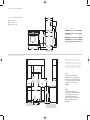
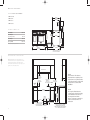
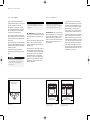
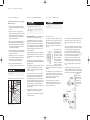
DUAL FUEL RANGES
INSTALLATION INSTRUCTIONS
Model Ser ies
C
M
Y
CM
MY
CY
CMY
K
ICBDF304
ICBDF366
ICBDF364C
ICBDF364G
ICBDF486C
ICBDF486G
ICBDF484CG
ICBDF484F
ICBDF606CG
ICBDF604CF
This cooktop is approved for use with
Natural gas .
Leave instructions with the owner.
W O L F DUAL FUEL RANGES
I N S TA L L AT I O N R E Q U I R E M E N T S
IMPORTANT NOTE: This installation must
be completed by a qualified installer,
service agency or gas supplier.
R AT I N G P L AT E
I N F O R M AT I O N
Model Number
Serial Number
C O N TA C T
I N F O R M AT I O N
Imported and
distributed by:
Multyflex
Website:
www.multyflex.com.au
IMPORTANT NOTE:
Statutory requirements: This
appliance shall be installed in
accordance with the manufacturer’s installation instructions,
local gas fitting regulations,
municipal building codes, electrical wiring regulations, and
AS/NZ5601 the Australian Standard
for gas installations. Refer also to
AS/NZ5601 for gas pipe sizing
tables.
Unsuitability for use in marine
craft, caravans or mobile homes,
unless each burner is fitted with a
flame safeguard.
As you read this use & care information,
take particular note of the CAUTION and
WARNING symbols when they appear.
This information is important for safe and
efficient use of the Wolf equipment.
signals a situation where minor injury or
product damage may occur if you do not
follow instructions.
states a hazard that may cause serious
injury or death if precautions are not
followed.
In addition, this use & care information may
signal an IMPORTANT NOTE which highlights
information that is especially important.
WOLF ® is a registered trademark of Wolf Appliance, Inc.
IMPORTANT NOTE: Save these installation
instructions for the local inspector’s use.
Installation to be carried out only by an
authorised person.
If the information in this book is
not followed exactly, a fire or
explosion may result, causing
property damage, personal injury
or death.
Do not modify this appliance.
Please read the entire installation instructions prior to installation.
Installer: please retain these instructions
for local inspector’s reference, then leave
them with the homeowner.
Homeowner: please read and keep these
instructions for future reference and be sure
to read the entire use & care information
prior to use.
IMPORTANT NOTE: This appliance must be
installed in accordance with local codes. The
correct voltage, frequency and amperage must
be supplied to the appliance from a dedicated,
grounded circuit which is protected by a
properly sized circuit breaker or time delay
fuse. The proper voltage, frequency, and
amperage ratings are listed on the product
rating plate.
Record the model and serial numbers before
installing the dual fuel range. Both numbers
are listed on the rating plate, located rear of
removable lower panel.
IMPORTANT NOTE:
Installation and service must be
performed by a qualified installer,
service agency or the gas supplier.
Do not store or use gasoline or
other flammable vapors and liquids
in the vicinity of this or any other
appliance.
A ventilation hood is recommended
for use with the Wolf dual fuel range.
WHAT TO DO IF YOU SMELL GAS:
Do not try to light any appliance.
Do not touch any electrical switch.
Do not use any phone in your
building.
Immediately call your gas supplier
from a neighbor’s phone. Follow the
gas supplier’s instructions.
If you cannot reach your gas
supplier, call the fire department.
I N S TA L L AT I O N I N S T R U C T I O N S
BEFORE Y O U S TA R T
Proper installation is your responsibility.
Installations must be performed by a
qualified or licensed contractor, plumber or
gas fitter, qualified or licensed by the state,
province or region where this appliance is
being installed. You must also ensure that
electrical installation is adequate and
conforms with all local codes and
ordinances.
Proper gas supply must be available; refer
to gas supply requirements on page 9.
Electrical ground is required; see electrical
requirements on page 10.
Check the location where the range will be
installed. The location should be away from
strong draft areas, such as windows, doors
and strong heating vents or fans. Do not
obstruct the flow of air. The area in which
you are installing this appliance must have
an adequate supply of fresh air to ensure
proper combustion and ventilation.
Make sure you have everything necessary
for proper installation. It is the responsibility of the installer to comply with the installation clearances specified on the product
rating plate. The rating plate is located rear
of removable lower panel.
All openings in the wall or floor where the
range is to be installed must be sealed.
The cooking range to be installed only on
the floor.
When installing the range under existing
cabinets where the installation does not
meet the minimum cabinet clearances,
install a ventilation hood or other noncombustible surface above the range to
avoid burn hazards. Refer to minimum
clearances on page 3.
V E N T I L AT I O N O P T I O N S
I N S TA L L AT I O N S P E C I F I C A T I O N S
IMPORTANT NOTE: A suitable ventilation
hood must be installed. We recommend a Wolf
Pro Ventilation Hood be installed with the Wolf
dual Fuel Range. Contact your Wolf dealer for
details.
MINIMUM CLEARANCES
IMPORTANT NOTE: When installing a ventilation hood, refer to the specific requirements
of the hood for the minimum dimension to
countertop.
I N S TA L L AT I O N S P E C I F I C A T I O N S
Wolf dual fuel ranges come in 762 mm,
914 mm, 1219 mm and 1524 mm widths.
Illustrations on pages 4–7 provide the overall
dimensions and installation specifications for
each width of dual fuel range.
Each range is designed to fit between cabinets
set at the distance specified by the unit. For
example, a 914 mm range will fit a 914 mm
opening. The exception is the 1524 mm unit
which will require a 1530 mm opening.
IMPORTANT NOTE: Cabinet opening dimensions shown in the installation specifications
illustrations must be used. These dimensions
provide for required clearances.
Each unit is designed with a terminal block on
the rear of the range. Have a qualified electrician or installer wire your unit from the electrical supply, through the knockout in the unit
base and to the terminal block on the range.
IMPORTANT NOTE: Locate the electrical
supply within dimensions shown in the
installation specifications illustrations and
flush with back wall.
IMPORTANT NOTE: Caution must be used in
planning the proper installation of the Wolf
dual fuel range to avoid fire or damage to
adjacent cabinetry or kitchen equipment.
Be sure to follow the minimum clearances
established in the finished rough opening
dimensions.
For installation against a rear combustible
surface a 254 mm classic stainless steel riser
must be used. Refer part number 804387.
Refer to the installation specifications illustration for your model on pages 4–7 for the exact
rough opening dimensions.
Maintain the following clearances to
combustible materials:
Minimum 457 mm clearance from bottom
of upper cabinet to countertop, within
152 mm minimum side clearance.
I S L A N D | P E N I N S U L A I N S TA L L A TIONS
For island installations, the range should
not be installed within an enclosure having an
adjacent rear wall less than 305 mm from the
rear of the unit that rises above the countertop.
For peninsula installations, the range must
have a 152 mm minimum clearance to the side
wall, left or right side, and 305 mm minimum
clearance to the rear wall.
Refer to the installation specifications illustration for your model on pages 4–7 for the exact
rough opening dimensions.
Failure to locate the range without the
proper clearances will result in a fire
hazard.
Minimum 762 mm clearance between countertop and bottom of wood or metal
cabinet, which is protected by not less than
6 mm flame retardant millboard covered
with not less than No. 28 MSG sheet steel,
.4 mm stainless steel, or .6 mm aluminum
or .5 mm copper.
Minimum 914 mm clearance between countertop and bottom of an unprotected wood
or metal cabinet.
Bottom of ventilation hood must be
600 mm minimum to 914 mm maximum
from countertop.
Refer to the installation specifications illustration for your model on pages 4–7 for the exact
rough opening dimensions and location of the
gas supply and electrical.
Wolf dual fuel ranges using natural gas will
operate up to an altitude of 2438 m without
any adjustment. Natural gas and LP gas installations from 2438 m to 3353 m need the high
altitude conversion kit.
3
WOLF
749 mm
DUAL FUEL RANGE
OVERALL DEPTH
699 mm
ICBDF304
1419
mm
235
mm
Overall Width
759 mm
Overall Height
(to cooking surface)
937 mm
Overall Depth
749 mm
Opening Width
762 mm
WITH
508 mm
RISER
1165
mm
WITH
254 mm
RISER
613 mm
911
mm
937 mm
OVERALL
HEIGHT TO
COOKING
SURFACE*
635 mm
1038
mm
664 mm
WITH
127 mm
RISER
937
mm
ISLAND
TRIM
759 mm
1194 mm
OVERALL WIDTH
*937 mm MIN TO 991 mm MAX.
IMPORTANT NOTE: In non-island applications,
a minimum 127 mm riser is required for model
ICBDF304.
VENTILATION HOOD
600 mm min
COUNTERTOP TO
COMBUSTIBLE
MATERIALS
min TO
COMBUSTIBLE
MATERIALS
(BOTH SIDES)
152 mm
600 mm min TO
914 mm max
TO BOTTOM OF
VENTILATION HOOD
330 mm
457 mm min
max
TO COUNTERTOP
762 mm
FINISHED ROUGH
OPENING WIDTH
914 mm
937 mm
216
mm
254 mm
LOCATION
OF GAS
SUPPLY
330 mm
LOCATION OF GAS AND
ELECTRICAL EXTENDS 57 mm LOCATION OF
ON FLOOR FROM BACK WALL ELECTRICAL
4
TO
COOKING
SURFACE
83 mm
ISLAND INSTALLATIONS: 305 mm MINIMUM
CLEARANCE FROM BACK OF RANGE TO
COMBUSTIBLE REAR WALL ABOVE COUNTERTOP–
0 mm TO NON-COMBUSTIBLE MATERIALS
Note A:
Side clearances. If the distance
measured from the periphery of the
nearest burner to any vertical surface
is less than 200 mm, the surface shall
be protected in accordance with
AS/NZ5601.
Note B:
The rangehood fitted above the
cooktop must be installed according
to the installation instructions for
the rangehood. A minimum
distance of 750 mm is required for a
range hood and 750 mm for an
exhaust fan.
I N S TA L L AT I O N I N S T R U C T I O N S
749 mm
914 mm D U A L F U E L R A N G E S
OVERALL DEPTH
699 mm
MODEL ICBDF366
MODEL ICBDF364C
235
mm
MODEL ICBDF364G
1445
mm
WITH
254 mm
RISER
616 mm
937 mm
OVERALL
HEIGHT TO
COOKING
SURFACE
911
mm
641 mm
1191
mm
WITH
254 mm
RISER
1064
mm
WITH
127 mm
RISER
911 mm
OVERALL DIMENSIONS
Overall Width
911 mm
Overall Height
(to cooking surface)
937 mm
Overall Depth
749 mm
Opening Width
914 mm
Dimensions may vary to ± 3 mm.
1194 mm
OVERALL WIDTH
LEGS AND CASTERS ALLOW
54 mm HEIGHT ADJUSTMENT
I N S TA L L AT I O N S P E C I F I C AT I O N S
IMPORTANT NOTE: In non-island applications,
a minimum 127 mm riser is required for model
ICBDF366 and minimum 254 mm riser required for
models ICBDF364C and ICBDF364G installed against
a combustible surface. The island trim and 127 mm
riser may only be used against a non-combustible
surface for models ICBDF364C and ICBDF364G.
VENTILATION HOOD
600 mm min
COUNTERTOP
TO COMBUSTIBLE
MATERIALS
762 mm min
FOR CHARBROILER
NOTE
A
330 mm
600 mm min TO
457 mm min
914 mm max
TO BOTTOM OF
VENTILATION HOOD
max
TO COUNTERTOP
NOTE
B
914 mm
FINISHED ROUGH OPENING WIDTH
216
mm
LOCATION OF GAS AND
ELECTRICAL EXTENDS 76 mm
ON FLOOR FROM BACK WALL
483 mm
LOCATION OF
ELECTRICAL
937 mm
TO
COOKING
SURFACE
381 mm
LOCATION
OF GAS
SUPPLY
914
mm
83 mm
ISLAND INSTALLATIONS: 305 mm MINIMUM
CLEARANCE FROM BACK OF RANGE TO
COMBUSTIBLE REAR WALL ABOVE COUNTERTOP–
50 mm TO NON-COMBUSTIBLE MATERIALS
Note A:
Side clearances. If the distance
measured from the periphery of the
nearest burner to any vertical surface
is less than 200 mm, the surface shall
be protected in accordance with
AS/NZ5601.
Note B:
The rangehood fitted above the
cooktop must be installed according
to the installation instructions for
the rangehood. A minimum
distance of 750 mm is required for a
range hood and 750 mm for an
exhaust fan.
5
W O L F DUAL FUEL RANGES
1219 mm D U A L F U E L R A N G E S
ICBDF484 CG
749 mm
OVERALL DEPTH
ICBDF484 F
699 mm
ICBDF486 C
235
mm
ICBDF486 G
1445
mm
WITH
254 mm
RISER
OVERALL DIMENSIONS
Overall Width
Overall Height
(to cooking surface)
Overall Depth
Opening Width
616 mm
1216 mm
911
mm
937 mm
OVERALL
HEIGHT TO
COOKING
SURFACE
937 mm
749 mm
641 mm
1191
mm
WITH
254 mm
RISER
1064
mm
WITH
127 mm
RISER
1219 mm
Dimensions may vary to ± 3 mm.
1194 mm
1216 mm
OVERALL WIDTH
LEGS AND CASTERS ALLOW
54 mm HEIGHT ADJUSTMENT
I N S TA L L AT I O N S P E C I F I C AT I O N S
IMPORTANT NOTE: In non-island applications, a
minimum 254 mm riser is required for all 1219 mm
models installed against a combustible surface.
The island trim and 127 mm riser may only be used
against a non-combustible surface.
VENTILATION HOOD
600 mm min
COUNTERTOP
TO COMBUSTIBLE
MATERIALS
330 mm
600 mm min TO
762 mm min
457 mm min
914 mm max
FOR CHARBROILER
TO BOTTOM OF
VENTILATION HOOD
NOTE
A
max
TO COUNTERTOP
NOTE
B
1219 mm
FINISHED ROUGH OPENING WIDTH
914
mm
254 mm
610 mm
LOCATION OF GAS AND
ELECTRICAL EXTENDS 76 mm
ON FLOOR FROM BACK WALL
6
LOCATION
OF GAS
SUPPLY
330 mm
LOCATION OF
ELECTRICAL
937 mm
TO
COOKING
SURFACE
83 mm
ISLAND INSTALLATIONS: 305 mm MINIMUM
CLEARANCE FROM BACK OF RANGE TO
COMBUSTIBLE REAR WALL ABOVE COUNTERTOP–
50 mm TO NON-COMBUSTIBLE MATERIALS
Note A:
Side clearances. If the distance
measured from the periphery of the
nearest burner to any vertical surface
is less than 200 mm, the surface shall
be protected in accordance with
AS/NZ5601.
Note B:
The rangehood fitted above the
cooktop must be installed according
to the installation instructions for
the rangehood. A minimum
distance of 750 mm is required for a
range hood and 750 mm for an
exhaust fan.
I N S TA L L AT I O N I N S T R U C T I O N S
749 mm
1524 mm D U A L F U E L R A N G E S
OVERALL DEPTH
699 mm
ICBDF606CF
I C B D F 6 04CF
235
mm
1445
mm
WITH
254 mm
RISER
616 mm
937 mm
OVERALL
HEIGHT TO
COOKING
SURFACE
911
mm
641 mm
1191
mm
WITH
254 mm
RISER
1064
mm
WITH
127 mm
RISER
1527 mm
OVERALL DIMENSIONS
Overall Width
1527 mm
Overall Height
(to cooking surface)
937 mm
Overall Depth
749 mm
Opening Width
1530 mm
Dimensions may vary to ± 3 mm.
1194 mm
OVERALL WIDTH
LEGS AND CASTERS ALLOW
54 mm HEIGHT ADJUSTMENT
I N S TA L L AT I O N S P E C I F I C AT I O N S
IMPORTANT NOTE: In non-island applications, a
minimum 254 mm riser is required for all 1524 mm
models installed against a combustible surface.
The island trim and 127 mm riser may only be used
against a non-combustible surface.
VENTILATION HOOD
600 mm min
COUNTERTOP
TO COMBUSTIBLE
MATERIALS
NOTE
A
330 mm
600 mm min TO
762 mm min
457 mm min
914 mm max
FOR CHARBROILER
TO BOTTOM OF
VENTILATION HOOD
NOTE
B
max
TO COUNTERTOP
1530 mm
FINISHED ROUGH OPENING WIDTH
787 mm
LOCATION OF GAS AND
ELECTRICAL EXTENDS 76 mm
ON FLOOR FROM BACK WALL
330 mm
LOCATION OF
ELECTRICAL
937 mm
TO
COOKING
SURFACE
254 mm
LOCATION
OF GAS
SUPPLY
914
mm
83 mm
ISLAND INSTALLATIONS: 305 mm MINIMUM
CLEARANCE FROM BACK OF RANGE TO
COMBUSTIBLE REAR WALL ABOVE COUNTERTOP–
50 mm TO NON-COMBUSTIBLE MATERIALS
Note A:
Side clearances. If the distance
measured from the periphery of the
nearest burner to any vertical surface
is less than 200 mm, the surface shall
be protected in accordance with
AS/NZ5601.
Note B:
The rangehood fitted above the
cooktop must be installed according
to the installation instructions for
the rangehood. A minimum
distance of 750 mm is required for a
range hood and 750 mm for an
exhaust fan.
7
W O L F DUAL FUEL RANGES
U N PA C K T H E R A N G E
Remove and discard all packing materials,
including cardboard and tape on the outside of
the range and inside the oven cavity.
Remove the box containing the oven racks,
oven rack guides and broiler pan from inside
the oven cavity. Be sure to do this for both
oven cavities on the 1524 mm range.
Remove the burner grates and styrofoam off
the top cooking surface. Be sure to remove the
burner caps packaged in styrofoam below the
burner grates.
Do not discard the angle iron supplied with the
range. This is the anti-tip bracket and must be
installed with the unit. Refer to anti-tip bracket
installation on page 11.
Carefully lift the range off the pallet and
remove the styrofoam from the bottom of the
unit.
The dual fuel range is very heavy. Use
caution when lifting and moving the unit.
Secure oven door(s) closed before
moving the unit.
OVEN DOOR R E M O VA L
Do not lift the range by the oven door
handle(s). This will damage the oven door
and hinges.
IMPORTANT NOTE: Before moving the range
into position, protect any finished flooring with
appropriate materials to avoid damage to the
floor.
The rear of the range has rolling casters which
allows for easy movement of the range by
picking up on the front of the unit. Refer to the
illustration below.
Failure to insert the hinge pin in the
appropriate hinge arm will cause damage
to the range. Minor injuries may occur.
IMPORTANT NOTE: The oven door(s) should
not be removed unless it is necessary to fit the
range through a tight doorway. Door removal
should only be done by a qualified service
technician or installer. Door removal and reinstallation may cause damage to the oven
porcelain interior.
The dual fuel range comes from the factory at
an overall height of 911 mm from floor to the
top of the bullnose, before any height adjustment. The legs and casters allow for 54 mm
height adjustment. Refer to the illustration
below. Use a 19 mm socket to adjust the rear
casters. Refer to the installation specifications
illustration for your model on pages 4–7 for
additional dimensions.
If removal of the oven door(s) is necessary, a
hinge pin, supplied with the range, will need to
be inserted in the appropriate hinge arm. For
each oven door, only one hinge arm is spring
loaded, requiring use of the hinge pin for
removal of the oven door. The hinge pin will
be found taped to the inside of the oven door.
For 762 mm and 914 mm ranges, the hinge pin
will be inserted through the hole in the right
hinge arm (facing the unit). On 1219 mm and
1524 mm ranges, the spring hinges are located
on the outer edges of the unit. On these units,
the left oven door will have the spring hinge
on the left side and the right oven door will
have the spring hinge on the right side. Refer
to the illustrations below for the location of the
spring hinge(s) for your model.
Casters allow for 54 mm
height adjustment
Place Hinge Pin on
Spring Hinge Side of Door
Rolling casters.
8
Spring hinge location for 762 mm
and 914 mm ranges.
Place Hinge Pins on
Spring Hinge Side of Door
Spring hinge locations for 1219 mm
and 1524 mm ranges.
I N S TA L L AT I O N I N S T R U C T I O N S
OVEN DOOR R E M O VA L
If removal of the oven door(s) is necessary,
follow these steps:
1) Remove the lower kickplate assembly to
access the lower hinge retainer mounting
screws.
2) Open the oven door to its fully opened
position and remove both upper and lower
hinge retainer mounting screws. The oven
gasket may have to be moved slightly to
access the bottom screws.
3) After removing the mounting screws, move
the hinge retainer plate forward slightly.
The hinge retainer plate will remain on the
door hinge assembly after the mounting
screws have been removed.
4) Insert the supplied door hinge pin through
the hole in the appropriate hinge arm. Refer
to the illustration below.
5) Carefully close the oven door to about a
60° angle from horizontal and lift the door
away from the oven. A slight rocking
motion may be required for removal.
6) For 1219 mm and 1524 mm ranges,
complete these steps for both oven doors
Do not lift or carry the oven door by the
door handle.
Hinge
Retainer
Plate
Upper Mounting
Screw
G A S S U P P LY R E Q U I R E M E N T S
EXPLOSION HAZARD —
Securely tighten all gas connections.
G A S S U P P LY C O N N E C T I O N
Never test for a gas leak with a match or
other flame.
Failure to do so can result in explosion,
fire or death.
IMPORTANT NOTE: The dual fuel range must
be connected to a regulated gas supply.
The rating plate, located rear of removable
lower panel, has information on the type of
gas that should be used. If this information
does not agree with the type of gas available,
check with the local gas supplier. A duplicate
plate can be attached to the inside top of an
adjacent cupboard.
This appliance appliance must be installed in a
position with the proper level of ventilation. Do
not obstruct the flow of combustion and ventilation air.
The gas pressure regulator supplied with the
appliance must be installed in line with the gas
pipe. (N.G. only).
If the appliance cannot be adjusted to perform
correctly contact Multyflex or the local gas
utility. For service contact telephone number
please refer page 13.
For pressure testing in excess of 3.5 kPa (1/2”
psig) the appliance and its individual shut-off
valve must be disconnected from the gas
supply piping system. For pressure testing of
the gas piping system at pressures equal to or
less than 3.5kPa (1/2”psig) the appliance must
be isolated from the gas supply system by
closing its individual shut off valve during any
pressure testing.
Gas connection:
The cooktop is adjusted to operate on the gas
type specified on the gas type label located on
the bottom of the unit. If in doubt as to the
type of gas available contact the network
operator or gas supplier for confirmation of
gas type.
The cooktop must be
connected to the gas
supply with upstream
connection of an isolation valve in accordance
with the respectively
valid regulations. We
recommend that the
isolation valve be fitted
prior to the cooktop to
enable isolation of the cooktop from the gas
supply. The valve must be easily accessible at
all times.
Fit regulator (N.G.) or Propane fitting (Propane)
directly to the R1/2” connection. direction for
gas flow is indicated on the rear of the regulator.
Check correct operation of each burner individually and in combination. Burner flames should
be clear blue, with no yellow tipping. If the
burners show any abnormality check that
burner heads are correctly located and refer to
the ‘trouble shooting’ guide on page 26 & 27 of
the Use and Care manual. If satisfactory
performance can not be obtained, contact
Multyflex or the local gas utility. For service
contact number refer page 13 of this booklet.
Note: These burner have no aeration adjustment.
It should be expressly noted that we cannot
accept any liability for direct or indirect damage
caused by wrong connection or improper instalThis appliance may be connected with a hose
lation. When being repaired, the appliance must
assembly, class B or class D in accordance to
always be
AS/NZS 1869. If connected with a hose assembly ensure that the gas
disconnected
supply connection point is accessible
from the main
with the appliance installed.
gas and electricity supply; if
The position of the inlet connection is
required,notify
measured from bottom RH rear of unit,
our customer
75 mm centre line from rear and 300 mm
service.
centre line from RH side.
The appliance should not be connected to a
combustion product evacuation system.
Hinge
Pin
Instruct the user in the operation of the appliance before leaving..
Kickplate
Oven door removal.
9
W O L F D U A L F U E L RA N G E S
GAS R AT I N G
E L EC TR I C A L R E QU IR E M E NT S
G A S R AT IN G
Verify that power is disconnected from the
electrical box before proceeding.
Refer to page 13
The complete appliance must be properly
grounded at all times when electrical power is
applied.
REQUIRED POWER SUPPLY
NOTE: Improper connection can result in a re
hazard.
Single phase: 220-240V AC; 50/60 Hz
3phase: 380-415V AC; 50/60 Hz
Before obtaining access to terminals, all supply
circuits must be disconnected.
MAXIMUM CONNECTED LOAD
762 mm and 914 mm Dual Fuel ranges:
Single phase: 19 amps
3phase: 18 amps
1219 mm Dual Fuel ranges:
Single phase: 35 amps
3phase: 18 amps
1524 mm Dual Fuel ranges:
Single phase: 38 amps
3phase: 18 amps
Refer to the wiring diagram showing the connections
for each lead to the terminal box on the unit.
Single phase wiring diagram
Open the terminal box to expose the screws with
corresponding numbers. Run the cord through the
strain relief hole and into the terminal box.
For Single Phase Install (Line, Neutral, Ground):
Loosen the 1, 5, and ground screws. Attach the
Neutral wire to the number 5 position. Line should be
attached to the 1 postion and attach the ground to
the corresponding ground screw.
For 3phase Install (L1, L2, L3, Neutral, Ground):
Loosen the 1, 2, 3 and remove the copper bars.
Loosen 5 and ground screws. Attach L1 to position
1. L2 to position 2. L3 to position 3. Neutral wire to
position 5 and attach the ground to the corresponding ground screw.
IMPORTANT NOTE: Connection of this appliance
should be through a fused connection unit or a
suitable isolator, which complies with national and
switch should
local safety regulations. The o
be easily accessible after the appliance has been
installed. If the switch is not accessible after installation (depending on country) an additional means of
disconnection must be provided for all poles of the
power supply. When switched
there must be an
all pole contact gap of 3 mm in the isolator switch.
This 3 mm contact disconnect gap must apply to
any isolator switch, fuses and/or relays according to
EN60335.
Copper bars must be removed from positions 1,
2, and 3 when connecting to 3phase power.
3phase wiring diagram
I M PO R T A N T N O T E
Be aware of local code s and ordinances
when insta lling you r service.
10
I N S TA L L AT I O N I N S T R U C T I O N S
ANTI-TIP BRACKET I N S T A L L A T I O N
This range can tip. Injury to persons could result.
Install the anti-tip bracket supplied with the range.
Raise the unit to its desired height by adjusting the front
legs and rear casters. The legs and casters allow for 54 mm
height adjustment. Use a 19 mm socket to adjust the rear
casters. The front legs are adjusted by rotating the bottom
hexagonal portion of the leg.
The anti-tip bracket can be installed by securing it to the wall
or floor using the supplied hardware.
Refer to the chart and illustration below to determine the
proper distance from the left side of the opening to the
anti-tip bracket. This will ensure the anti-tip bolt properly
engages the bracket.
MODEL
DRYWALL APPLICATIONS
ANTI-TIP BOLT ADJUSTMENT
After properly positioning the anti-tip bracket, use wall
anchors to fasten it to the wall. Using a Philips screwdriver
or a low rpm screw gun, drive the anchor into the surface
of the wallboard until the two cutting blades penetrate the
surface. Use gentle forward pressure to rotate the collar until
flush with the surface of the wall. Refer to the illustrations
below. Use #8 screws and flat washers to fasten the anti-tip
bracket to the wall.
Once the bracket is secured in place, adjust the anti-tip bolt
at the back of the range so the top of the washer is 22 mm
maximum from the floor. Slide the range into the opening and
verify the anti-tip bolt is engaged. Refer to the illustrations
below.
IMPORTANT NOTE: The top of the range must be level.
Use the adjustable front legs and the rear casters to level
the range.
WOOD FLOOR APPLICATIONS
A
5 mm
914 mm Range
14 mm
1219 mm Range
5 mm
1524 mm Range
8 mm
IMPORTANT NOTE: The oven door(s) should not be removed
unless it is necessary to fit the range through a tight
doorway. Door removal should only be done by a qualified
service technician or installer. Door removal and reinstallation may cause damage to the oven porcelain interior.
CONCRETE FLOOR APPLICATIONS
2) Holding the oven door at an approximate 30° angle from
vertical, slide the hinges into the openings until the
bottom hinge arms drop fully into the hinge receptacles.
4) Reinstall the hinge retainer plate with upper and lower
mounting screws.
OVEN DOOR R E I N S T A L L A T I O N
762 mm Range
1) Hold the oven door on both sides and position it with
door hinges aligned with openings in the oven frame.
3) Open the oven door to its fully opened position. Remove
the hinge pin from the appropriate hinge arm. Refer to
the
illustration below.
IMPORTANT NOTE: Pre-drill holes if difficulty is encountered during installation of the wall anchor. For hard wallboard or double-board construction, use a 6 mm drill bit. For
solid plaster, use a 11 mm drill bit.
After properly positioning the anti-tip bracket, drill 5 mm pilot
holes through the floor. Use #12 screws and flat washers to
secure the bracket to the floor.
If oven door(s) have been removed, follow these steps to
reinstall:
5) Open and close the door completely to ensure that it is
properly installed.
6) For 1219 mm and 1524 mm ranges, complete these steps
for both oven doors.
7) Reinstall the lower kickplate assembly.
IMPORTANT NOTE: Fully extend the hinge claw which is
opposite the hinge pin location and insert into the hinge
pocket prior to inserting opposite side. This will ease the
installation of the oven door.
After properly positioning the anti-tip bracket drill 10 mm
holes into the concrete a minimum of 38 mm deep. Use 10
mm wedge anchors to secure the bracket to the floor.
Do not lift or carry the oven door by the door handle.
Hinge
Retainer
Plate
WALL
ANCHOR
ANTI-TIP
BRACKET
Upper Mounting
Screw
Hinge
Pin
A
ANTI-TIP
BRACKET
ANTI-TIP
BOLT
ANTI-TIP
DEVICE
ENGAGED
22 mm MAX
Kickplate
Anti-tip bracket location.
Wall anchor installation.
Anti-tip bolt adjustment.
Anti-tip bolt engaged.
Oven door reinstallation.
W O L F DUAL FUEL RANGES
C O O K T O P O P E R AT I O N
VERIFY R A N G E O P E R AT I O N
REMOVING T H E R A N G E
TROUBLES H O O T I N G
The cooktop burner uses an electronic igniter in
place of a standing pilot. When the cooktop control
knob is pushed in and turned to the
position,
the system creates a spark to light the burner. This
sparking continues for 4 seconds or until the electronic ignition senses a flame, which ever comes
first. If the igniter fails to ignite the gas in 4 seconds,
the gas safety shutoff valve will close, eliminating
the gas flow for 5 seconds. The valve will reopen
after the purge time of 5 seconds, and the igniter
will automatically attempt to re-ignite the gas. This
cycle of events is attempted 3 times. After the third
attempt, in order for gas to flow to the burner once
again, the user must return the knob to the
position and then turn the knob to the
position.
IMPORTANT NOTE: Prior to operating
the range, be sure to read the entire
Wolf dual fuel ranges use & care information included with the range for
important safety and service information.
If removing the dual fuel range is necessary for
cleaning or service, shut off the gas supply.
Disconnect the gas supply and electrical
connections to the unit, then remove the
range. Reinstall in the reverse order and be
sure to check the gas connection for leaks.
IMPORTANT NOTE: If the dual fuel range
does not operate properly, follow these
troubleshooting steps:
Install the oven rack guides onto the
shoulder screws located on the interior
side walls of the oven. Slide the oven
racks onto the support racks within the
oven. There are three racks per oven,
except for the 457 mm oven which has
two racks. Place the broiler pan and grid
on a rack within the oven, if desired.
Refer the Wolf dual fuel ranges use & care
information included with the range for
cleaning recommendations.
To check operation of the cooktop burner, push in
and turn the control knob to the
position. The
flame should light within four seconds.
If the burner does not light properly, turn the control
knob to the
position. Check that the burner
head is in the proper position. Check that the power
supply cord is plugged in and that the circuit breaker
or house fuse has not blown.
Check operation again; If flame is not established
within the ignition cycle time, release the knob, open
a door and wait 1 minute before attempting a new
ignition procedure.
If the flames are extinguished - for any reason
whatever - turn OFF the control knob and wait at
least 1 minute before retrying to ignite the burner.
Ensure that the flames do not extinguish when you
reduce to low flame quickly. Check correct operation
of each burner individually and in combination.
FLAME HEIGHT AND APPEARANCE
The flame on natural gas should be blue with a
deeper blue core. and no yellow tipping. If burners
show any abnormality check that burner heads are
correctly located and refer to the ‘ trouble shooting
guide’ on this page. If satifactory performance can
not be obtained, contact Multyflex. For service
contact number refer page 13 of this booklet.
IMPORTANT NOTE: Initial lighting of the surface
burners may take slightly longer, as air in the
system must be purged before gas can be supplied
to the burner.
12
Turn on the power supply to the range.
The control panel should be closed (no
visible control pads). Touch and slightly
depress the flame graphic on the hidden
control panel to open.
Set the time of day by pressing the
touch pad, scroll to the desired time by
using the
or
arrows, then touch
. After setting the time, the hidden
control panel can be closed. The control
panel does not have to be open to
operate the oven.
Select any of the eight cooking modes
by using the oven control knob bezel
and turning to the desired mode. Once
the mode has been selected, the temperature can be adjusted by turning the
temperature readout knob clockwise to
increase the temperature or counterclockwise to decrease the temperature.
Verify that the oven is coming up to
temperature. For a 1219 mm or 1524 mm
range, follow this procedure for the both
ovens.
IMPORTANT NOTE: A small amount of
smoke and odor may be noticed during
the initial break-in period. Refer to the
use & care information for additional
information.
Verify that power is being supplied to the
range.
Check the gas supply and electrical
connections to ensure that the installation
has been completed correctly.
Check that gas valves are turned to the ON
position.
Be sure to disconnect the gas supply and
electrical connections before removing
the range.
Follow troubleshooting procedures as
described in the Wolf dual fuel ranges
use & care information.
If the range still does not work, contact a
Wolf dealer. Do not attempt to repair the
range yourself. Wolf
is not responsible for service required to
correct a faulty installation.
I N S TA L L AT I O N I N S T R U C T I O N S
SERVICE I N F O R M A TI O N
BEFORE CALLING FOR SERVICE
Serial Number
Before calling your Wolf dealer, refer to the
troubleshooting guide on page 12. Check
the household fuse or circuit breaker to see if it
has been blown or tripped and that the electrical connection to the appliance has not been
disconnected. A power outage may also have
caused a disruption in service.
Installation Date
Wolf Dealer and Phone
GSCS20230
SAI GLOBAL
AS4551
Made in USA
Model No: ICBDF304
Serial No:
Gas type
Test point press. (kPa)
Injector sizes (mm)
RHF
RHR
LHF
LHR
NG
1.0
LPG
2.75
1.80
1.80
1.80
1.35
1.09
1.09
1.09
0.89
Total Consumption (MJ/h)
51.0
51.1
GSCS20230
SAI GLOBAL
AS4551
Made in USA
Model No: ICBDF366
Serial No:
NG
1.0
LPG
2.75
1.80
1.80
1.09
1.09
LHF
LHR
Total Consumption (MJ/h)
1.80
1.35
79.0
1.09
0.89
79.1
Gas type
Test point press. (kPa)
Injector sizes (mm)
RHF
RHR
Grill
LHF
LHR
Total Consumption (MJ/h)
GSCS20230
SAI GLOBAL
AS4551
Made in USA
NG
1.0
LPG
2.75
1.80
1.80
1.78
1.80
1.35
66.0
1.09
1.09
1.09
1.09
0.89
66.1
Gas type
Test point press. (kPa)
Injector sizes (mm)
RHF
RHR
Griddle
LHF
LHR
Total Consumption (MJ/h)
Made in USA
Model No: ICBDF484CG
Serial No:
Model No: ICBDF364G
Serial No:
Model No: ICBDF364C
Serial No:
Gas type
Test point press. (kPa)
Injector sizes (mm)
RHF/CF
RHR/CR
MF018
GSCS20230
SAI GLOBAL
AS4551
Made in USA
The wiring diagram covering the control circuit
is located rear of the removable lower panel.
1300 808 859
MF028
MF022
MF027
For service call:
GSCS20230
SAI GLOBAL
AS4551
WIRING D I A G R A M
Model Number
MF016
When requesting information, literature,
replacement parts or service, always refer to
the model and serial number of your dual fuel
range. This information is found on the
product rating plate located rear of the removable lower panel. Refer to the illustration below.
Record the rating plate information
below for future reference.
NG
1.0
LPG
2.75
1.80
1.80
1.70
1.80
1.35
66.0
1.09
1.09
1.09
1.09
0.89
66.1
Gas type
Test point press. (kPa)
Injector sizes (mm)
RHF
RHR
Grill
Griddle
LHF
LHR
NG
1.0
LPG
2.75
1.80
1.80
1.78
1.70
1.80
1.35
1.09
1.09
1.09
1.09
1.09
0.89
Total Consumption (MJ/h)
81.0
81.1
Electrical compliance: in accordance with
AS/NZS3100 240 V AC, 4.5 kW/19 Amps, 50 Hz
Electrical compliance: in accordance with
AS/NZS3100 240 V AC, 4.5 kW/19 Amps, 50 Hz
Electrical compliance: in accordance with
AS/NZS3100 240 V AC, 4.5 kW/19 amps, 50 Hz
Electrical compliance: in accordance with
AS/NZS3100 240 V AC, 8.4 kW/35 Amps, 50 Hz
Imported & distributed by
Suite 1, 151 Barkley Avenue. Burnley VIC 3121
t: +61 3 9421 0232
Imported & distributed by
Suite 1, 151 Barkley Avenue. Burnley VIC 3121
t: +61 3 9421 0232
Imported & distributed by
Suite 1, 151 Barkley Avenue. Burnley VIC 3121
t: +61 3 9421 0232
Imported & distributed by
Suite 1, 151 Barkley Avenue. Burnley VIC 3121
t: +61 3 9421 0232
Imported & distributed by
Suite 1, 151 Barkley Avenue. Burnley VIC 3121
t: +61 3 9421 0232
Made in USA
Gas type
Test point press. (kPa)
Injector sizes (mm)
RHF
RHR
French top
LHF
LHR
Total Consumption (MJ/h)
GSCS20230
SAI GLOBAL
AS4551
Made in USA
NG
1.0
LPG
2.75
1.80
1.80
1.80
1.80
1.35
65.0
1.09
1.09
1.09
1.09
0.89
65.1
Gas type
Test point press. (kPa)
Injector sizes (mm)
RHF
RHR
Grill
LHF/CF/CR
LHR
Total Consumption (MJ/h)
GSCS20230
SAI GLOBAL
AS4551
Made in USA
NG
1.0
LPG
2.75
1.80
1.80
1.78
1.80
1.35
94.0
1.09
1.09
1.09
1.09
0.89
94.1
Gas type
Test point press. (kPa)
Injector sizes (mm)
RHF/CF
RHR/CR
Griddle
LHF
LHR
Total Consumption (MJ/h)
MF026
GSCS20230
SAI GLOBAL
AS4551
Made in USA
NG
1.0
1.80
1.80
1.70
1.80
1.35
94.0
LPG
2.75
1.09
1.09
1.09
1.09
0.89
94.1
GSCS20230
SAI GLOBAL
AS4551
Made in USA
Model No: ICBDF606CG
Serial No:
Model No: ICBDF604CF
Serial No:
Model No: ICBDF486G
Serial No:
Model No: ICBDF486C
Serial No:
Model No: ICBDF484F
Serial No:
MF030
MF029
MF017
GSCS20230
SAI GLOBAL
AS4551
MF023
Electrical compliance: in accordance with
AS/NZS3100 240 V AC, 4.5 kW/19 Amps, 50 Hz
NG
1.0
Gas type
Test point press. (kPa)
Injector sizes (mm)
RHF
RHR
Grill
French top
LHF
LHR
LPG
2.75
1.80
1.80
1.78
1.80
1.80
1.35
1.09
1.09
1.09
1.09
1.09
0.89
Total Consumption (MJ/h)
80.0
81.1
Gas type
Test point press. (kPa)
Injector sizes (mm)
RHF/CF
RHR/CR
Grill
Griddle
LHF
LHR
NG
1.0
LPG
2.75
1.80
1.80
1.78
1.70
1.80
1.35
1.09
1.09
1.09
1.09
1.09
0.89
Total Consumption (MJ/h)
109.0
109.1
Electrical compliance: in accordance with
AS/NZS3100 240 V AC, 8.4 kW/35 Amps, 50 Hz
Electrical compliance: in accordance with
AS/NZS3100 240 V AC, 8.4kW/35 Amps, 50 Hz
Electrical compliance: in accordance with
AS/NZS3100 240 V AC, 8.4kW/35 Amps, 50 Hz
Electrical compliance: in accordance with
AS/NZS3100 240 V AC, 9.1 kW/38 Amps, 50 Hz
Electrical compliance: in accordance with
AS/NZS3100 240 V AC, 9.1 kW/38 amps, 50 Hz
Imported & distributed by
Suite 1, 151 Barkley Avenue. Burnley VIC 3121
t: +61 3 9421 0232
Imported & distributed by
Suite 1, 151 Barkley Avenue. Burnley VIC 3121
t: +61 3 9421 0232
Imported & distributed by
Suite 1, 151 Barkley Avenue. Burnley VIC 3121
t: +61 3 9421 0232
Imported & distributed by
Suite 1, 151 Barkley Avenue. Burnley VIC 3121
t: +61 3 9421 0232
Imported & distributed by
Suite 1, 151 Barkley Avenue. Burnley VIC 3121
t: +61 3 9421 0232
IMPORTED &
D I ST R I B U T E D B Y :
MultyFlex
C O N TA C T
I N F O R M AT I O N
Website:
www.multyflex.com. au
The information and images in this book are the
copyright property of Wolf Appliance, Inc., an
affiliate of Sub-Zero, Inc. Neither this book nor any
information or images contained herein may be
copied or used in whole or in part without the
express wri tten permission of Wolf Appliance, Inc.,
an affiliate of Sub-Zero, Inc.
©Wolf Appliance, Inc. all rights reserved.
13
Wiring diagram
14
Wiring diagram
15
Wiring diagram
16
Wiring diagram
17
Imported & distributed by Multyflex
www.multyflex.com.au
MF038