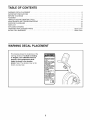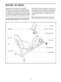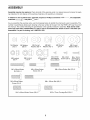
1
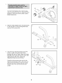
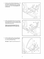
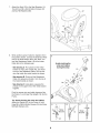
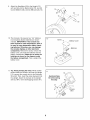
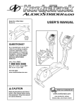
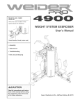
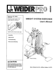
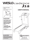
Model No. 83t.2t8tt.0
Serial No.
Write the serial number in the
BIKE EXERCISER
User's Manual
space above for reference.
Serial Number
Decal
• Assembly
• Operation
• Maintenance
• Part List and Drawing
Sears, Roebuck and Co., Hoffman Estates, IL 60179
TABLE OF CONTENTS
WARNING DECAL PLACEMENT ..............................................................
IMPORTANT PRECAUTIONS
................................................................
BEFORE YOU BEGIN ......................................................................
ASSEMBLY ...............................................................................
HOW TO USE THE EXERCISE CYCLE ........................................................
MAINTENANCE AND TROUBLESHOOTING
...................................................
EXERCISE GUIDELINES ...................................................................
PART LIST ..............................................................................
EXPLODED DRAWING ....................................................................
ORDERING REPLACEMENT PARTS ..................................................
90 DAY FULL WARRANTY ..........................................................
WARNING DECAL PLACEMENT
This drawing shows the location(s) of the
warning decal(s). If a decal is missing
or illegible, call 1-866-699-3756 and
request a free replacement decal.
Apply the decal in the location
shown. Note: The decal(s) may not be
shown at actual size.
• M suse oft_is mach ne
may result in serious
injury,
• Read user's mLanL
alu
prior to use and foUow
all warnings and
instructions.
• Do not allow children
on or around machine.
• Pedals continue to
spin when you stop
pedaling.
• Spinning pedals can
cause injury.
• Reduce pedal speed
in a controlledmanner.
• User weight must not
exceed 250 pounds.
• Replace label if
damaged, illegible, or
removed.
2
[_
2
3
4
5
11
14
15
18
19
Back Cover
Back Cover
IMPORTANT
PRECAUTIONS
3
BEFORE YOU BEGIN
Congratulations for selecting the new WESLO ®
PURSUIT CT 3.8 R exercise cycle. Cycling is one of
the most effective exercises for increasing cardiovascular fitness, building endurance, and toning the body.
The PURSUIT CT 3.8 R exercise cycle offers a selection of features designed to let you enjoy this healthful
exercise in the convenience and privacy of your home.
after reading this manual, please see the back cover
of this manual. To help us assist you, note the product
model number and serial number before contacting
us. The model number and the location of the serial
number decal are shown on the front cover of this
manual.
Before reading further, please review the drawing
below and familiarize yourself with the labeled parts.
For your benefit, read this manual carefully before
you use the exercise cycle. If you have questions
Console
Thumb Pulse Sensor
Handlebar
Resistance Knob
Backr,
Pedal/Strap
Seat
Adjustment Knob
Seat Frame
Seat Handle
4
ASSEMBLY
Assembly requires two persons. Place all parts of the exercise cycle in a cleared area and remove the packing materials. Do not dispose of the packing materials until assembly is completed.
In addition to the included tools, assembly requires
wrenches Q_,
a Phillips screwdriver _-_,
two adjustable
and pliers _.
As you assemble the exercise cycle, use the drawings below to identify the small parts used in assembly. The
number in parentheses below each drawing is the key number of the part, from the PART LIST near the end of
this manual. The number following the parentheses is the quantity needed for assembly. Note: Some small
parts may have been preassembled. If a part is not in the hardware kit, check to see if it has been preassembled. If a part is missing, call t-888-533-t333.
M4 Washer
(70)-2
M6 Washer
(68)-8
M6 Locknut
(63)-4
M6 x 30ram Button
Bolt (64)-4
M6 Curved
Washer (69)-4
M8 Locknut
(10)-4
M8 Split
Washer (42)-3
MIO Locknut
(65)-2
M6 x 35mm Button
Screw (61)-8
M8 x 20ram Button
M8 Washer
(54)-4
M4x 5mm
Self-tapping
Screw (66)-2
M8 Curved
Washer (46)-2
M4 x8mm
Screw (29)-2
M4x 15mm
Self-tapping
Screw (47)-4
M8 x 65ram Button Bolt (72)-2
M8 x 125mm Bolt (62)-2
Screw (34)-3
MIO x 60mm Button Screw (33)-2
MIO x 75mm Carriage Bolt (30)-2
5
Turn the Front Stabilizer (2) so that the large
holes are facing the Frame (1). Attach the Front
Stabilizer to the Frame with two M10 x 60mm
Button Screws (33).
Holes
Attach the Rear Stabilizer (6) to the Seat Frame
(5) with two M10 x 75ram Carriage Bolts (30)
and two M10 Locknuts (65).
2,
2
30
,
Insert the end of the Seat Frame (5) into the
Frame (1). Next, firmly press the Frame
Bushing (56) into the Frame. Attach the Frame
Bushing to the Frame with two M4 x 5mm Selftapping Screws (66). Then, tighten the
Adjustment Knob (9) into the Frame.
56
Carefully tip the exercise cycle onto its side.
Attach the two Bumpers (57) to the Frame (1)
with two M4 x 8mm Screws (29) and two M4
Washers (70). Then, tip the exercise cycle
upright.
5
6
Attach the Left and Right Seat Brackets (14, 15)
to the Seat Frame (5) with two M8 x 125mm
Bolts (62), four M8 Washers (54), and two M8
Locknuts (10) as shown. Do not tighten the
Locknuts yet.
4.
54 10
54 10
15
Attach a Seat Handle (59) to the round tube on
the Left Seat Bracket (14) with two M6 x 30ram
Button Bolts (64), two M6 Curved Washers (69),
and two M6 Locknuts (63).
5.
59
Attach the other Seat Handle (59) to the
Right Seat Bracket (t5) in the same way.
59
.
Attach the Backrest (60) to the Seat Brackets
(14, 15) with four M6 x 35mm Button Screws
(61) and four M6 Washers (68).
See step 4. Tighten the two M8 Locknuts (10).
15
68
61
68
7
61
7.
8.
Attach the Seat (12) to the Seat Brackets (14,
15) with four M6 x 35mm Button Screws (61)
and four M6 Washers (68).
While another person holds the Upright (13) in
the position shown, connect the Extension Wire
(52) to the Reed Switch Wire (43). Next, connect the Resistance Cable (19) to the Lower
Cable (45) in the following way:
8
Avoid pinching the
• See drawing A. Pull upward on the metal
bracket on the Lower Cable (45), and insert
the tip of the Resistance Cable (19) into the
wire clip inside the metal bracket as shown.
diurres; t disCablee;
• See drawing B. Firmly pull the Resistance
Cable (19) upward and slide it into the top of
the metal bracket as shown.
13
/_
45 =,_'/" ._--34
34_2__
• See drawing C. Using pliers, squeeze the
prongs on the upper end of the metal bracket
together.
Push the excess wire and cable downward into
the Frame (1), and insert the Upright (13) into the
Frame.
Tip: Avoid pinching the wires and cables.
Attach the Upright (13) to the Frame (1) with
three M8 x 2Omm Button Screws (34) and three
M8 Split Washers (42).
A
._ Metal
_
Bracket
1]-45
8
o
Metal j
Bracket
9.
Attach the Handlebar (53) to the Upright (13)
with two M8 x 65mm Button Bolts (72), two M8
Curved Washers (46), and two M8 Locknuts (10).
9
53
72
10. The Console (16) requires four "AA" batteries
(not included); alkaline batteries are recommended. IMPORTANT: If the Console has
been exposed to cold temperatures,
allow it
to warm to room temperature before inserting batteries. Otherwise, you may damage
the console displays or other electronic
components. Remove the screw, remove the
battery cover, and insert the batteries into the
battery compartment. Make sure to orient the
batteries as shown by the diagram inside
the battery compartment.
Then, reattach the
battery cover.
10
11. Tip: Avoid pinching the wires. While another
person holds the Console (16) near the Upright
(13), connect the console wire to the Extension
Wire (52). Then, insert the wires downward into
the Upright. Attach the Console to the Upright
with four M4 x 15mm Self-tapping Screws (47).
11
16
\
Avoid pinching
the wires during
this step
52
47
Wire
9
12. Identify the Left Pedal (24), which is marked
with an "L" sticker. Using an adjustable wrench,
firmly tighten the Left Pedal counterclockwise
into the left arm of the Crank (21). Tighten the
Right Pedal (not shown) clockwise into the right
arm of the Crank. IMPORTANT: Tighten beth
Pedals as firmly as possible. After using the
exercise cycle for one week, retighten the
Pedals. For best performance, keep the
Pedals tightened.
12
Adjust the strap on the Left Pedal (24) to the
desired position, and press the end of the strap
onto the tab on the Left Pedal (24). Adjust the
strap on the Right Pedal (not shown) in the
same way.
Tab _
Strap
13. Make sure that all parts are properly tightened before you use the exercise cycle. After assembly is completed, some extra parts may be left over. Place a mat under the exercise cycle to protect the floor.
10
HOW TO USE THE EXERCISE CYCLE
HOW TO ADJUST THE SEAT FRAME
FEATURES OF THE CONSOLE
For effective exercise, the seat should be in the proper
position. As you pedal, there should be a slight bend
in your knees when the pedals are in the most forward
position.
H
Pace
Guide ..
Knob
RPM
SCAN
PULSE
CALORIES
SPEED
TIME
DISTANCE
il
11
Seat
Frame
Thumb Pulse Sensor
To adjust the seat frame, first loosen the adjustment
knob on the frame. Slide the seat frame forward or
The console offers a selection of features designed to
make your workouts more effective. As you pedal, the
console will provide continuous exercise feedback.
You can even measure your heart rate using the builtin thumb pulse sensor.
backward to the desired position. Then, retighten the
adjustment knob.
HOW TO ADJUST THE PEDALING RESISTANCE
To increase the
resistance of the
The console also offers two pace workouts that prompt
you to vary your pedaling pace while guiding you
through an effective workout.
pedals, turn the
resistance knob
clockwise; to
decrease the resistance, turn the
knob counterclockwise. IMPORTANT: Stop turning the knob
when turning
becomes difficult,
or damage may
result.
To use the manual mode, see page 12. To use a
pace workout, see page 13.
Before using the console, make sure that batteries are
installed (see assembly step 10 on page 9). If there is
a sheet of clear plastic on the display, remove the
plastic.
Resistance
Knob
t/_
11
HOW TO USE THE MANUAL MODE
t.
When you turn on
the console, the
Indicators
scan mode will be
selected automatically. One indica'_
tor will appear
below the word
Scan to show that
RPMSPEEDTIME DISTANCE
the scan mode is
selected, and a
second indicator will show which information is
currently displayed. Note: If you have selected a
different mode, press the Display button repeatedly
to reselect the Scan mode.
Turn on the console.
To turn on the console, press the On/Reset button
or begin pedaling. The entire display and the pace
guide will light for a moment; the console will then
be ready for use.
2.
..1
Select the manual mode.
When you turn
on the console,
the manual
mode will be
SCAN
PULSE
CALORIES
tt!.tlltl!
M'MM
To select the
speed, time, dis-
selected. If you
have selected a
RPM SPEED
TIME
DISTANCE
pace workout,
reselect the
manual mode by pressing the Pace Workout button repeatedly until zeros appear in the display.
3.
SCAN PULSECALORIES
mode for
tance,
or continucalories
_1_9
ous display, press
the Display butRPMSPEEDTIME DISTANCE
ton repeatedly.
The indicators will
show which mode is selected. Make sure there is
not an indicator below the word Scan.
Follow your progress with the display.
The display can show the following workout information:
Note: The console can show
RPM--The RPM meter on the left side of the display indicates your approximate pedaling pace
(revolutions per minute).
SCAN PULSECALORIES
Distance--This mode shows the distance you
have pedaled, in miles or kilometers.
speed and dis&=,
tance in either
miles or kilometers. The letters
RPM SPEED
TIME
DISTANCE
"mph" or "km!h"
will appear in the
display to show which unit of measurement is
selected. To change the unit of measurement, first
hold down the On/Reset button for a few seconds.
An "E" (for English) or an "M" (for metric) will
appear in the display. Press the Display button to
change the unit of measurement. Note: When the
batteries are replaced, it may be necessary to reselect the desired unit of measurement.
Calories--This mode shows the approximate number of calories you have burned.
To reset the display, press the On/Reset button.
Speed--This mode shows your pedaling speed, in
miles per hour (mph) or kilometers per hour
(kin/h).
Time--This mode shows the elapsed time. Note:
When a pace workout is selected, the display
shows the time remaining in the workout instead of
the elapsed time.
Pulse--This mode shows your heart rate when
you use the thumb pulse sensor.
To pause the console, stop pedaling. If the time is
displayed, it will flash. To continue your workout,
simply resume pedaling.
Scan--This mode shows the speed, time, distance, calories, and pulse modes, for a few seconds each, in a repeating cycle. Note: The pulse
mode will appear only when you are using the
pulse sensor.
12
4.
Measure your heart rate if desired.
HOW TO USE A PACE WORKOUT
To measure your
SCAN
PULSE
CALORIES
heart rate, stop
pedaling and
place your
thumb on the
[
.
J
pulse sensor. Do
RPM SPEED
TIME
DISTANCE
not press too
hard, or the circulation in your thumb will be restricted and
your pulse will not be detected. After a few seconds, the heart-shaped indicator in the display will
flash steadily, two dashes will appear, and then
your heart rate will be shown. Hold your thumb on
the pulse sensor for about 15 seconds for the
most accurate reading.
1. Turn on the console.
,33M
See step 1 on page 12.
2.
To select a pace
workout, press the
button
repeatedly
Pace Workout
until P1 or P2
SCAN pULSECALORIES
p
appears in the
RPMSPEEDTIME DISTANCE
display. A few seconds after you
select a pace workout, the display will show the
duration of the workout.
if the displayed heart rate appears to be too high
or too low, or if your heart rate is not displayed, lift
your thumb off the pulse sensor for a few seconds. Then, place your thumb on the pulse sensor
as described above.
3.
Begin pedaling to start the workout.
Each pace workout consists of 30 one-minute
segments. One target pace is programmed for
each segment. Any time the target pace is about
to change, the display will flash for a few seconds
to alert you.
Make sure you are applying the proper amount of
pressure to the pulse sensor. Try the pulse sensor
several times until you become familiar with it.
Remember to stand still while measuring your
heart rate.
.
Select a pace workout.
During the workout, the pace
guide will prompt
you to keep your
pedaling pace
near the target
pace setting for the current segment. When the
left indicator lights, increase your pace; when the
right indicator lights, decrease your pace. When
the center indicator lights, maintain your current
pace. Important: The pace guide is intended
only to provide a goal. Make sure to pedal at a
pace that is comfortable for you.
When you are finished exercising, the console
will turn off automatically.
If the pedals do not move for a few seconds, the
console will pause. If the pedals do not move for a
few minutes, the console will turn oft and the display will be reset.
The display can show the time remaining in the
workout. If you stop pedaling for a few seconds,
the workout will pause and the time will flash if it
is displayed. To restart the workout, simply
resume pedaling.
4.
Follow your progress with the display.
See step 3 on page 12.
5.
Measure your heart rate if desired.
See step 4 at the left.
6.
When you are finished exercising, the console
will turn off automatically.
See step 5 at the left.
13
MAINTENANCE
AND TROUBLESHOOTING
HOW TO ADJUST THE BELT
Inspect and tighten all parts of the exercise cycle regularly. Replace any worn parts immediately.
If you can feel the pedals slip while you are pedaling,
even when the resistance is at the highest level, the
belt may need to be adjusted.
To clean the exercise cycle, use a damp cloth and a
small amount of mild detergent. IMPORTANT: To
avoid damage to the console, keep liquids away
from the console and keep the console out of
direct sunlight.
To adjust the belt, remove the left and right shield covers. Next, loosen, but de net remove, the M8 x 20ram
Bolt (23). Loosen the two M8 Locknuts (10), one on
each side of the Flywheel (37). Then, tighten the M6
Lecknuts (63), one on each side of the Flywheel, until
the belt is properly tightened. Finally, tighten the M8
Locknuts (10) and the M8 x 20mm Bolt (23). Then,
reattach the shield covers.
BATTERY REPLACEMENT
If the console display becomes dim, the batteries
should be replaced; most console problems are the
result of low batteries. To replace the batteries, see
assembly step 10 on page 9.
HOW TO ADJUST THE REED SWITCH
If the console does not display correct feedback, the
reed switch should be adjusted. To adjust the reed
switch, first remove the left shield cover.
38
Next, turn the resistance knob to the lowest setting.
With the left shield cover removed, locate the Reed
Switch (43). Turn the Crank (21) until the Magnet (38)
is aligned with the Reed Switch. Loosen, but do not
remove, the M4 x 15mm Self-tapping Screw (47).
Slide the Reed Switch slightly closer to or away from
the Magnet, and then retighten the Screw. Turn the
Crank for a moment. Repeat until the console displays
correct feedback. When the Reed Switch is correctly
adjusted, reattach the left shield cover.
14
EXERCISE GUIDELINES
Burning Fat--To burn fat effectively, you must exercise at a low intensity level for a sustained period of
time. During the first few minutes of exercise, your
body uses carbohydrate calories for energy. Only after
the first few minutes of exercise does your body begin
to use stored fat calories for energy. If your goal is to
burn fat, adjust the intensity of your exercise until your
heart rate is near the lowest number in your training
zone. For maximum fat burning, exercise with your
heart rate near the middle number in your training
zone.
Aerobic Exercise--If your goal is to strengthen your
cardiovascular system, you must perform aerobic
exercise, which is activity that requires large amounts
of oxygen for prolonged periods of time. For aerobic
exercise, adjust the intensity of your exercise until
your heart rate is near the highest number in your
training zone.
These guidelines will help you to plan your exercise
program. For detailed exercise information, obtain a
reputable book or consult your physician. Remember,
proper nutrition and adequate rest are essential for
successful results.
WORKOUT GUIDELINES
EXERCISE INTENSITY
Warming up--Start with 5 to 10 minutes of stretching
and light exercise. A warm-up increases your body
temperature, heart rate, and circulation in preparation
for exercise.
Whether your goal is to burn fat or to strengthen your
cardiovascular system, exercising at the proper intensity is the key to achieving results. You can use your
heart rate as a guide to find the proper intensity level.
The chart below shows recommended heart rates for
Training Zone Exercise--Exercise for 20 to 30 minutes with your heart rate in your training zone. (During
the first few weeks of your exercise program, do not
keep your heart rate in your training zone for longer
than 20 minutes.) Breathe regularly and deeply as you
exercise-never hold your breath.
fat burning and aerobic exercise.
165
155
145
140
130
125
115
___
145
138
130
125
120
115
125
118
110
103
£t?
110
105
95
90
20
30
40
50
60
70
Cooling down--Finish
with 5 to 10 minutes of
stretching. Stretching increases the flexibility of your
muscles and helps to prevent post-exercise problems.
80
EXERCISE FREQUENCY
To find the proper intensity level, find your age at the
bottom of the chart (ages are rounded off to the nearest ten years). The three numbers listed above your
age define your "training zone." The lowest number is
the heart rate for fat burning, the middle number is the
heart rate for maximum fat burning, and the highest
number is the heart rate for aerobic exercise.
To maintain or improve your condition, complete three
workouts each week, with at least one day of rest
between workouts. After a few months of regular exercise, you may complete up to five workouts each
week, if desired. Remember, the key to success is to
make exercise a regular and enjoyable part of your
everyday life.
15
SUGGESTED STRETCHES
The correct form for several basic stretches is shown at the right.
Move slowly as you stretch--never bounce.
1. Toe Touch Stretch
Stand with your knees bent slightly and slowly bend forward from
your hips. Allow your back and shoulders to relax as you reach
down toward your toes as far as possible. Hold for 15 counts, then
relax. Repeat 3 times. Stretches: Hamstrings, back of knees and
back.
2. Hamstring
Stretch
Sit with one leg extended. Bring the sole of the opposite foot
toward you and rest it against the inner thigh of your extended leg.
Reach toward your toes as far as possible. Hold for 15 counts,
then relax. Repeat 3 times for each leg. Stretches: Hamstrings,
lower back and groin.
3. Calf/Achilles Stretch
With one leg in front of the other, reach forward and place your
hands against a wall. Keep your back leg straight and your back
foot flat on the floor. Bend your front leg, lean forward and move
your hips toward the wall. Hold for 15 counts, then relax. Repeat 3
times for each leg. To cause further stretching of the achilles tendons, bend your back leg as well. Stretches: Calves, achilles tendons and ankles.
4. Quadriceps Stretch
With one hand against a wall for balance, reach back and grasp
one foot with your other hand. Bring your heel as close to your buttocks as possible. Hold for 15 counts, then relax. Repeat 3 times
for each leg. Stretches: Quadriceps and hip muscles.
5. Inner Thigh Stretch
Sit with the soles of your feet together and your knees outward.
Pull your feet toward your groin area as far as possible. Hold for 15
counts, then relax. Repeat 3 times. Stretches: Quadriceps and hip
muscles.
16
NOTES
17
PART LIST-- Model No. 831.21 811.0
Key No. Qty.
Description
R0608A
Key No. Qty.
Description
1
2
3
4
5
6
7
8
9
10
11
12
13
14
1
1
1
2
1
1
2
2
1
7
1
1
1
1
Frame
Front Stabilizer
Left Shield Cover
Front Stabilizer Cap
Seat Frame
Rear Stabilizer
Seat Handle Cap
Rear Stabilizer Cap
Adjustment Knob
M8 Locknut
C-magnet
Seat
Upright
Left Seat Bracket
38
39
40
41
42
43
44
45
46
47
48
49
50
51
2
1
2
5
3
1
1
1
2
9
1
1
2
1
Magnet
Flywheel Axle
M10 Small Washer
M4 x 25mm Screw
M8 Split Washer
Reed SwitchANire
Crank Bearing Set
Lower Cable
M8 Curved Washer
M4 x 15mm Self4apping Screw
Spring
Bracket
Foam Grip
M6 x 45mm Bolt
15
16
17
1
1
1
Right Seat Bracket
Console
Left Shield
52
53
54
1
1
4
Extension Wire
Handlebar
M8 Washer
18
19
20
21
22
23
1
1
1
1
1
1
Right Shield
Resistance Control/Cable
Seat Frame Bushing
Crank/Pulley
Reed Switch Clamp
M8 x 20mm Bolt
55
56
57
58
59
60
1
1
2
4
2
1
M5 x 40mm Screw
Frame Bushing
Bumper
Square Cap
Seat Handle
Backrest
24
25
26
27
28
29
30
31
32
33
34
35
1
2
1
1
2
2
2
2
1
2
3
1
Left Pedal/Strap
6000Z Bearing
Right Pedal/Strap
Resistance Knob
U_bracket
M4 x 8mm Screw
M10 x 75mm Carriage Bolt
Eyebolt
M6 Nut
M10 x 60mm Button Screw
M8 x 20mm Button Screw
Belt
61
62
63
64
65
66
67
68
69
70
71
72
8
2
6
4
2
2
1
8
4
2
2
2
M6 x 35mm Button Screw
M8 x 125mm Bolt
M6 Locknut
M6 x 30mm Button Bolt
M10 Locknut
M4 x 5mm Self-tapping Screw
M5 Curved Washer
M6 Washer
M6 Curved Washer
M4 Washer
Handlebar Cap
M8 x 65mm Button Bolt
36
37
1
1
Right Shield Cover
Flywheel
-
User's Manual
Hex Key
Note: Specifications are subject to change without notice. See the back cover of this manual for information
about ordering replacement parts. *These parts are not illustrated. If a part is missing, call t-888-533-t333.
18
EXPLODED DRAWING--
Model No. 831.21 811.0
R0608A
59
63
64
68
16
58
50
62
64
4
34
27
38
34
39
63
44
25
28
4
37
56
65
47
30
19
For Sears professional
installation of home appliances
and items like garage door openers and water heaters.
1-800-4-MY-HOME
® (1-800-469-4663)
Call anytime, day or night (U.S.A. and Canada)
www.sears.com
www.sears.ca
Our Home
For repair of carry-in items like vacuums, lawn equipment,
and electronics, call or go on-line for the location of your nearest
Sears Parts & Repair Center.
1-800-488-1222
Call anytime, day or night (U.S,A, only)
Se=l/t
® Registered
@ Marca
Registrada
TM
Trademark
/
Trademark
/ T_,!Marca de F&bdca
SM
/
Service
Mark of Sears Brands,
LLC
/ SM Marca de Servicio
de Sears Brands,
LLC
90 DAY FULL WARRANTY
this Sears bike exerciser fails due to a defect in material or workmanship within 90 days of the date of
purchase, call 1-800-4-MY-HOME _'(1-800-469-4663) to arrange for free repair (or replacement if repair
proves impossible).
This warranty does not apply when the bike exerciser is used commercially or for rental purposes.
This warranty gives you specific legal rights, and you may also have other rights which vary from state
to state.
Sears, Roebuck and Co., Noffman Estates, IL 60179
J
J
Part No. 266633 R0608A
Printed in China © 2008 ICON IP, Inc.