1
TECHNICAL SERVICE MANUAL
VARIABLE REFRIGERANT FLOW A/C SYSTEM
NONE MODULAR DIGITAL SCROLL R-410A 50 HZ
Read this manual before installation and operation
Make sure that it is well kept for later reference
Contents
___________________________________________________________________________________
YDS None Modular Digital scroll
___________________________________________________________________________________
-1-
Contents
___________________________________________________________________________________
Contents
Part 1 General Information……………………………………………….…………………………………..………4
1. YDS system series…………………………………………………………………….…….…………….……..…….6
What is YDS………………………………………………………………………………….…………….….…………6
Features of YDS ……………………………………………………………………….………….………........…….6
2. Nomenclatures…………………………………………………………………………..……………………………..15
Part 2 Units selection base on cooling load……………………………………………………………………..16
Part 3 Outdoor Units……………………………………………………………………………………………………26
1. Specifications……………………………………………………………………………………………………………28
2. Capacity table……….…………………………………………………………………….………………….……..…29
3. Dimensions and required installation space…………………..……………………….…………………….49
4. Piping diagram………………………………………………………………………………………………………….53
5. Noise level………………………………………………………………………………………………………………..57
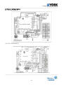
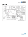
6. Outdoor wiring diagram……………………………………………………………………………………………..59
7. Trouble shooting ………………………………………………………………...………….………….….…………61
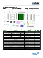
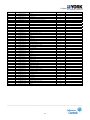
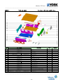
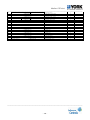
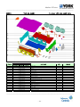
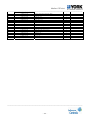
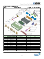
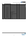
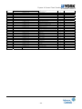
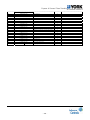
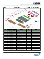
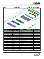
8. Explode view and spare part list………………………………………………………………………………….64
Part 4 Indoor Units…………………………………………….………………………………………………………..78
1. Introduction………………………………………………………………………….…………………….…………….70
2. Four-way cassette type………………………………………………………………………………….………….71
3. Wall mounted type…………………………………………………………………………………………………..102
4. Ceiling &Floor type…………………………………………………………………………………………………..125
5. Medium static pressure type………………………………………………………..……………………...…....151
6. Expose and conceal floor standing………………………………………………………..………………......183
7. Hi ESP duct………………………..……………………………………………………..….………………………….220
Part 5 Installation……………………………………………………………………………………..…………………239
1. Summarize of Installation……………………………………………………………………………………………241
2. Installation of outdoor unit ……………………………………………………………………………………..…245
3. Installation of indoor unit …………………………………………………………………………………………..246
4. Installation of refrigerant pipe ……………………………………………………………………..…………….247
5. Processing & installation of drainage pipe……………………………………………………………………268
6. Insulation work…………….………...………..………………………….………………….………………………..271
7. Pipeline installation…………..………………………………………….……………………………………………274
8. Electric installation…………..………………………………………………….………….….….…………………278
___________________________________________________________________________________
-2-
Contents
___________________________________________________________________________________
Part 6 Control System ………………………………………………………………………………………………...288
1. Control system………….….………….……...…………….……………………………………………..……….. ..290
2. Indoor unit central control monitor system …………..…………………………………………….………..301
3. Outdoor unit central monitor system…………………………………………………………………..………..319
4. 3rd intelligent network control & monitor system…………..…………………………………..…...…….325
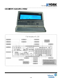
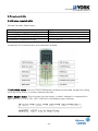
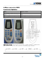
5. Remote controller…………………………………………………………………………………………………......364
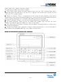
6. Receiver display………………………………………………………..…………………………….………………...381
___________________________________________________________________________________
-3-
General information
___________________________________________________________________________________
Part I General Information
___________________________________________________________________________________
-4-
General information
___________________________________________________________________________________
Contents
1. YDS system series………………………………………………………………………………………….….….…….6
What is YDS…………………………………………………………………………………………………….…………6
Features of YDS …………………………………………………………………………………….………....……….6
2. Nomenclatures…………………………………………………………………………………………………………..15
___________________________________________________________________________________
-5-
General information
___________________________________________________________________________________
1. YDS system series
1.1
What is YDS
The YDS (YORK Digital Scroll Air Conditioner) air conditioning system is operated by a
variable-capacity compressor and is accommodated by multiple evaporators (indoor units). It is
considered as the next-generation modular system with high efficiency air conditioning in the
world.
It has undoubtedly changed the face of cooling associated with high-storied buildings. It
provides a broad range of different applications for settings such as offices, hotels and schools.
With the advantage of easy installation and simple controlling system and so on, the YDS system
can meet the demands of the air conditioning market better.
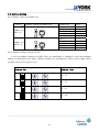
1.2 Features of YDS
(1) Variable compressor
The world’s first PWM (Pulse Width Modulation) compressor controls the cooling and
heating capacity automatically according to the load.
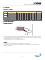
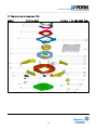
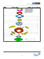
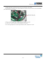
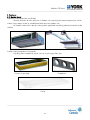
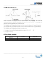
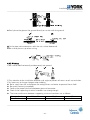
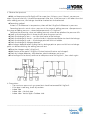
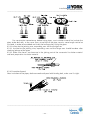
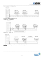
Principle of the digital scroll compressor:
[1] Composition
The solenoid valve is installed for the compressor’s loading/ unloading between the upper
part of the fixed scroll and the suction pipe.
[2] Mechanism
a. When the solenoid valve is turned off, the fixed scroll is close to the orbiting (Loading).
b. When the solenoid valve is turned on, the fixed scroll is separated from the orbiting
scroll. (Unloading)
___________________________________________________________________________________
-6-
General information
___________________________________________________________________________________
c. This process controls the On/Off time of the valve and the rotating refrigerants in the
circle thus adjusting the capacity.
d. The cooling capacity of the outdoor units is adjusted automatically, according to the
number of operating indoor unit(s).
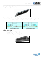
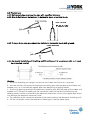
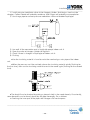
[3] PWM (Pulse Width Modulation) Valve
PWM valve is the valve to take away the fixed scroll by lifting up through the difference
of pressure after the digital scroll compressor being connected to the outlet and inlet of suction.
Therefore, the capacity of compressor is controlled automatically according to the operation
status such as loading when the valve is closed or unloading when the valve is opened. PWM
means the ON/OFF signal to the valve for loading /unloading.
___________________________________________________________________________________
-7-
General information
___________________________________________________________________________________
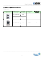
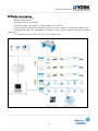
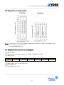
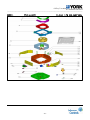
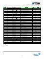
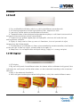
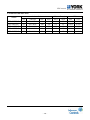
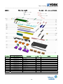
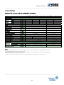
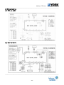
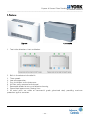
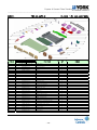
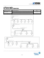
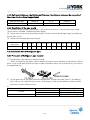
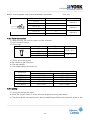
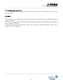
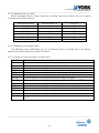
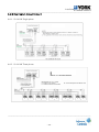
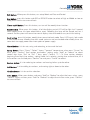
(2) Multi matching with several indoor units
Outdoor units
Appearance
Power supply
Capacity(kW)
1 Ph-220-240V-50Hz
10/14
3 Ph-380-415V-50Hz
10/14
3 Ph-380-415V-50Hz
28
Refrigerant
Max. connectible
indoor units
R-410A
6/8
R-410A
16
___________________________________________________________________________________
-8-
General information
___________________________________________________________________________________
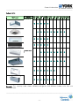
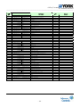
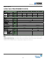
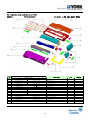
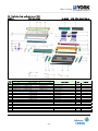
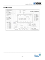
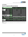
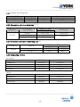
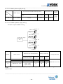
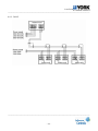
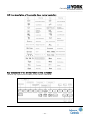
Indoor Units
YDS Product
Capacity
Refrigerant
2.2
kW
2.8
kW
3.6
kW
4.5
kW
5.6
kW
7.1
kW
8.0
kW
9.0
kW
11.2
kW
14.0
kW
28.0
kW
Four-way Cassette (Compact)
Four-way Cassette
Wall mount
Wall mount (EXV Integrated)
Floor ceiling
R-410A 50 Hz
Medium static Duct
Expose Floor standing
Conceal Floor standing
Remark: This capacity table shows different refrigerant and different indoor units that are
available now.
___________________________________________________________________________________
-9-
General information
___________________________________________________________________________________
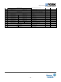
(3) High efficiency
EER is up to 3.2.
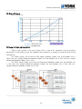
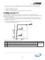
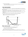
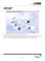
(4) Long & single piping system
Digital scroll system is the only system that is free of oil separator and oil recycling
equipment. In the loading state, the speed of the refrigerant is enough to move oil back to the
compressor.
For 28Kw system, the maximum Pipe length between indoor unit and outdoor unit is
150m, the max. Height difference between indoor unit and outdoor unit is 50m, the max. Height
difference between indoor units is 15m.
For 10kw, 14kw system, the maximum Pipe length between indoor unit and outdoor unit
is 70m, the max. Height difference between indoor unit and outdoor unit is 20m, the max.
Height difference between indoor units is 8m.
___________________________________________________________________________________
- 10 -
General information
___________________________________________________________________________________
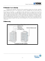
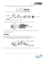
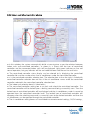
(5) Advanced oil return technology.
Combining the electronic control and the mechanical control, the oil level controller
keeps appropriate oil level in the compressor crankcase. Equipped with oil balance pipe and
low-pressure accumulator, it is applicable to both low-pressure & high-pressure oil cycling
system. Besides, with the innovative design of one-way valve and capillary, the system can
meet the continual oil level change of digital compressor and protect the compressor in whole
hog. The digital Scroll Compressor is in the state of loading or unloading. In the loading state,
the full speed operation of the compressor motor ensures the refrigerant has enough power to
bring the oil back to the compressor. In the unloading state, there is no oil moving out of since
there is no refrigerant output, the inertia of the refrigerant can also bring some oil back to the
compressor.
(6) Space saving
___________________________________________________________________________________
- 11 -
General information
___________________________________________________________________________________
(7) Simple installation and easy maintenance.
Easy installation
The structure of the YDS system and the piping work are simple, thus the installation is
easy.
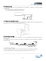
Indoor units installation: Whole series indoor units have the same gas/liquid connection
size for R-410A ,and by flare nut connection, it is easy to connect and decrease your installation
cost up to 30%.
Independent system
The YDS system can be installed by stages and the owners can install their system at
their convenient time. Thus the system has less installation time limit.
- Installation by stages can avoid the non installment for the new project.
- Convenient installation is realized for the rebuilt project.
No need special maintenance work
Simple refrigerant piping system without any complicated maintenance work
Compared with the water-cooled system:
Without water-cooled system, there is no need to clean the water pipe
No full-time person is needed to do the maintenance work
Module construction enables the system to be free from large-scale repair regularly.
___________________________________________________________________________________
- 12 -
General information
___________________________________________________________________________________
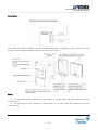
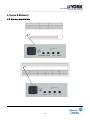
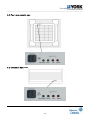
(8) Flexible control system
Wireless remote control
Wired remote control
Individual indoor unit control
Individual indoor unit control & group indoor units control
Central control monitor Realize group control of multi-indoor units (Max:64 indoor units)
Intelligent Net-work Air-conditioner control& monitor System Realize intelligent network
control via
PC monitoring system (Max: 16 CCM, 1024 indoor units)
___________________________________________________________________________________
- 13 -
General information
___________________________________________________________________________________
(9) No electromagnetic disturbance.
YDS Digital Scroll II System causes no electromagnetic disturbance, since the loading and
unloading of compressor are merely mechanical movement. This special feature makes the
Digital Scroll System applicable to telecommunication companies, power stations, and all kinds
of precise science labs.
___________________________________________________________________________________
- 14 -
General information
___________________________________________________________________________________
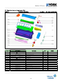
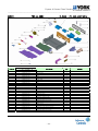
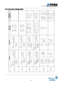
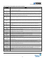
2. Nomenclature
1
YDS
YDV
6
5
6
7
Configuration
YORK Digital Scroll
YORK AC/DC
Inverter
Power Hz
50 Hz
60 Hz
50/60 Hz
7
E
I
2
- XX
-
Capacity
x 100 W
3
W
Type
Outdoor
4
Fluid
A R22
5
1
E
High wall Everest
B R407C
2 220-240V-3-50Hz / 200-230V-3-60Hz
H
F
G
K
Q
R
S
T
U
V
W
High wall EXV Integrated
Floor Ceiling
4-Way Cassette Compact
4-Way Cassette
1-Way Cassette
Conceal Floor standing
Expose Floor standing
Hi ESP Ducted
Me ESP Ducted
Low ESP Ducted
Slim Me ESP Ducted
C R410A
3 380-415V-3-50Hz / 460V-3-60Hz
4 115V-1-60Hz
Expansion device (ID)
Not fixed on unit
Fixed on unit
7
A
B
C
D
F
Generation
First generation
Second generation
Third generation
Forth generation
Fifth generation
-
8
3
A
B
Power phase
220-240V-1-50Hz / 208-230V-1-60Hz
Optional
2-Pipe system
3-Pipe system
Front intake
Below intake
Example
YDS-280WC35A - York Digital Scroll Outdoor unit 28 kW, R-410A, 3 Ph 50 Hz, 1st generation
YDS-22KC15IA
- York Digital Scroll Cassette type 2.2 kW, R-410A, 1 Ph 50 Hz, EXV. fixed on
unit, 1st generation
___________________________________________________________________________________
- 15 -
Unit selection base on cooling load
___________________________________________________________________________________
Part 2 Unit selection base on cooling load
___________________________________________________________________________________
- 16 -
Unit selection base on cooling load
___________________________________________________________________________________
Contents
1. Introduction ……………………………………………………………………………………….……………………18
2. Unit Selection (with cooling load)……………………………………………………………………….………18
___________________________________________________________________________________
- 17 -
Unit selection base on cooling load
___________________________________________________________________________________
1. Introduction
Refrigerant
Power supply
1 Ph-220-240V-50Hz
R-410A
3 Ph-380-415V-50Hz
Model
Capacity (kW)
10
14
10
14
28
YDS-100WC15A
YDS-140WC35A
YDS-100WC35A
YDS-140WC35A
YDS-280WC35A
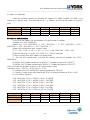
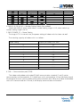
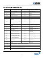
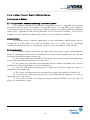
2. Unit selection (Based on Cooling Load)
2.1) Indoor unit selection
1. After calculated the heat load of rooms, according to the local weather parameter and
area, cubage, structure of rooms, selecting the nearest load capacity indoor units with given
load.
2. Selecting the proper indoor units should include the type of indoor units (Such as the
four-way cassette, duct and so on).
3. Pay attention to the requirements of customers and local corresponding design
standards.
CAUTION: The described capacity may be different from each indoor unit according to
combination. So the real capacity should be calculated with outdoor unit capacity table.
2.2) Outdoor unit selection
The allowable combination is described on the indoor combination total capacity index
table.
For the standard of the indoor unit and outdoor unit combination, select the nearest
value that the total indoor unit capacity index is less than 130% outdoor unit capacity index.
Indoor unit combination total capacity index.
Outdoor Units
Outdoor Unit
YDS-100WC15A
YDS-140WA15A
YDS-100WC35A
YDS-140WC15A
YDS-280WC35A
130%
13
18.2
13
18.2
36.4
100%
10(ISO)
14(ISO)
10(ISO)
14(ISO)
28(ISO)
Indoor unit combination
90%
80%
9
8
12.6
11.2
9
8
12.6
11.2
25.2
22.4
70%
7
9.8
7
9.8
19.6
60%
6
8.4
6
8.4
16.8
50%
5
7
5
7
14
Indoor units
Unit size
22
28
36
45
56
71
80
90
112 140 280
Capacity index (kW)
2.2
2.8
3.6
4.5 5.6 7.1
8.0
9.0 11.2 14.0 28.0
___________________________________________________________________________________
- 18 -
Unit selection base on cooling load
___________________________________________________________________________________
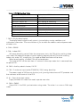
2.3) Real function data
(1) Select the exact table according to outdoor unit model and combination rate using
outdoor unit capacity table. According to given indoor and outdoor temperature, find outdoor
unit capacity and power input using the table. Each indoor unit capacity (Power input) is
calculated as follows.
IUC=OUC × INX/TNX
IUC: Each indoor unit capacity
OUC: Outdoors unit capacity
INX: Each indoor unit capacity index
TNX: Total capacity index
(2) According to different pipe lengths and height difference, the indoor unit capacity will
change accordingly. If the changed capacity is smaller than load, replace it with a larger capacity
indoor unit and repeat the selecting progress.
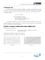
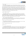
2.4) Variation in capacity in accordance with the length of refrigerant piping.
(1) Cooling capacity modification
Effectual cooling capacity
= Rated cooling capacity × Modification coefficient
= ([1] x [2] x [3] x [4])
[1] Modification coefficient of indoor W.B. temperature.
[2] Modification coefficient of outdoor D.B. temperature.
___________________________________________________________________________________
- 19 -
Unit selection base on cooling load
___________________________________________________________________________________
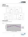
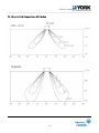
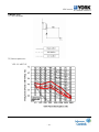
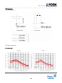
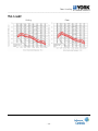
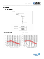
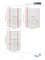
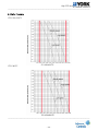
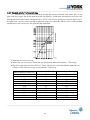
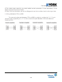
[3] Coefficient of the length and high difference of refrigerant pipe.
Outdoor unit 10 kW
Outdoor unit 14 kW
Outdoor unit 28 kW
___________________________________________________________________________________
- 20 -
Unit selection base on cooling load
___________________________________________________________________________________
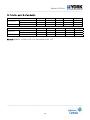
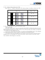
[4] Modification coefficient of indoor air
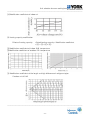
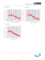
(2) Heating capacity modification
Effectual heating capacity
=Rated heating capacity × Modification coefficient
= ([1] x [2] x [3] x [4])
[1] Modification coefficient of indoor W.B. temperature
[2]Modification coefficient of outdoor D.B. temperature
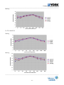
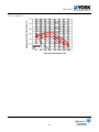
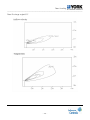
[3] Modification coefficient of the length and high difference of refrigerant pipe
Outdoor unit 10 kW
___________________________________________________________________________________
- 21 -
Unit selection base on cooling load
___________________________________________________________________________________
Outdoor unit 14 kW
Outdoor unit 28 kW
[4] Modification coefficient of indoor air-volume changing rate
___________________________________________________________________________________
- 22 -
Unit selection base on cooling load
___________________________________________________________________________________
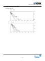
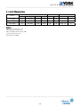
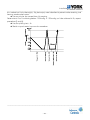
2.5) Temperature range of operation
Notes: These figures assume the following operation conditions (Indoor and outdoor units):
1. Equivalent pipe length: 10 m
2. Height difference: 0 m
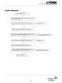
2.6) Example for unit selection with cooling load
1) Given condition
[1] Design condition (Cooling: Indoor 20°C (WB), Outdoor 35°C (DB))
[2] Cooling load
Location
Load (Kw)
Room A
2.1
Room B
2.8
Room C
3.5
Room D
4.6
Room E
5.8
Room F
7.2
[3] Power supply unit: 3 Faze 380V 50Hz
[4] Pipe length: 50m
[5] Height difference: 30m
___________________________________________________________________________________
- 23 -
Unit selection base on cooling load
___________________________________________________________________________________
2) Indoor unit selection
Select the suitable capacity for condition of ‘Indoor 20°C (WB), Outdoor 35°C (DB)’ using
indoor unit capacity table. The selected result is as follows. (Assuming the indoor unit type is
duct)
Location
Load (KW)
Unit size
Capacity (KW)
Room A
2.1
22
2.5
Room B
2.8
28
3.1
Room C
3.5
36
3.9
Room D
4.6
45
4.9
Room E
5.8
56
6.0
Room F
7.2
71
7.6
3) Outdoor unit selection
[1] Assume the indoor unit and outdoor unit combination as follows
Outdoor unit: YDS-280WC35A
Indoor unit: YDS -22UC15EA× 1, YDS -28UC15EA × 1, YDS -36UC15EA× 1,YDS 45UC15EA × 1, YDS -56UC15EA × 1, YDS -71UC15EA × 1,
Indoor unit combination total capacity index
22 × 1 +28 × 1+ 36 × 1 +45 × 1+ 56 × 1 + 71 × 1 = 258, (258/ 280) × 100%= 92%
[2] Result: Because it is within 50~130%, it is a ”Right” selection.
[3] Real function data with indoor unit combination
a . For the 92% combination, calculate the cooling capacity of outdoor unit (YDS 280WA35A).
26.41KW←90% (Indoor temperature: WB 20°C, Outdoor temperature: DB 35°C)
29.33KW←100% (Indoor temperature: WB 20°C, Outdoor temperature: DB 35°C)
Then calculated the outdoor capacity in 92% combination index:
Therefore: 26.41 + {(29.33 – 26.41)/ 10} ×2= 27.00;
b. Outdoor unit (YDS-280WC35A) cooling temperature: DB 35°C)
c. Capacity change factor with pipe length (50m) and height difference (30m): 0.905
d. Each cooling capacity
YDS -22UC15EA: 27.00 × 22/258 × 0.905 = 2.08(KW)
YDS -28UC15EA: 27.00 × 28/258 ×0.905 = 2.65 (KW)
YDS -36UC15EA: 27.00 × 36/258 ×0.905 = 3.41 (KW)
YDS -45UC15EA: 27.00 × 45/258 ×0.905 = 4.26 (KW)
YDS -56UC15EA: 27.00 × 56/258 ×0.905= 5.30 (KW)
YDS -71UC15EA: 27.00 × 71/258 ×0.905 = 6.70 (KW)
Location
Load (KW)
Unit size
Capacity (KW)
Room A
2.1
22
2.08
Room B
2.8
28
2.65
Room C
3.5
36
3.41
Room D
4.6
45
4.26
Room E
5.8
56
5.30
Room F
7.2
71
6.70
___________________________________________________________________________________
- 24 -
Unit selection base on cooling load
___________________________________________________________________________________
[4] Conclusion: Generally, we think this result is acceptable, so we can think we have
accomplished the calculation. But if you think this result is not acceptable, you can repeat the
over process.
Remark: In these samples, we don’t consider the other capacity modification index and assume
them is 1.
___________________________________________________________________________________
- 25 -
Outdoor
___________________________________________________________________________________
Part 3 Outdoor
___________________________________________________________________________________
- 26 -
Outdoor
___________________________________________________________________________________
Contents
1. Specifications……………………………………………………………………………………………………………28
2. Capacity table……….…………………………………………………………………….………………….……..…29
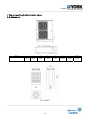
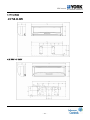
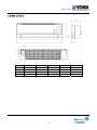
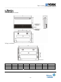
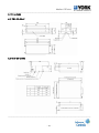
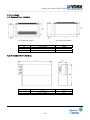
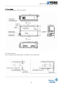
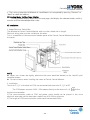
3. Dimensions and required installation space…………………..……………………….…………………….49
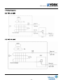
4. Piping diagram………………………………………………………………………………………………………….53
5. Noise level………………………………………………………………………………………………………………..57
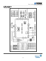
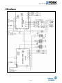
6. Outdoor wiring diagram……………………………………………………………………………………………..59
7. Trouble shooting ………………………………………………………………...………….………….….…………91
8. Explode view and spare part list………………………………………………………………………………….64
___________________________________________________________________________________
- 27 -
Outdoor
___________________________________________________________________________________
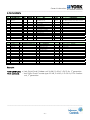
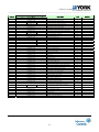
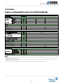
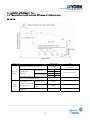
1. Specification
Outdoor YDS-100-840 WA15/35A R-22 50Hz
Model
Power supply
Ph-V-Hz
YDS-100WC15A
YDS-140WC15A
1Ph-220-240 V-50 Hz
YDS-100WC35A
YDS-140WC35A
YDS-280WC35A
3 Ph-220-240 V-50 Hz
Nominal capacity
Cooling
Heating
Capacity
Input
Capacity
Input
kW
kW
kW
kW
10.0
3.6
12.0
3.5
14.0
4.2
16.0
3.9
10.0
3.5
12.0
3.4
14.0
4.5
16.0
4.4
29.0
8.9
30.0
8.7
kW
A
A
6.23
28
142
6.39
30
156
6.78
10
64
7.75
12
64
12.5
21
64
14
8.5
Internal
14
8.5
32.2
18.5
Electrical parameter
Max. input consumption
Max. current
Starting current
Compressor
Capacity
Rated current (RLA)
Thermal protector
Refrigerant oil
Btu/h
A
Inner
ml
50500
31.4
1890
1800
3600
W
uF
r/min
158×2
5×2
890/590
138*2
3.5x2
800
700/450
10
670/450
Motor
Input
Capacitor
Speed
Coil
a. Number of rows
b. Tube pitch(a)x row pitch(b)
c. Fin spacing
d. Fin type (code)
e. Tube outside dia.and type
f. Coil length x height x width
g. Number of circuits
2
mm
mm
2.5
25.4×22
1.8
Hydrophilic aluminum
Ф9.53
Inner grove copper tube
715x1220x44
8
mm
mm
870x980x60
10x2
Performance
Air flow
Noise level
m3/h
dB
6000
55
10000
68
Piping connection
Liquid side/ Gas side
Max. Refrigerant pipe length
Max. Difference in level
Refrigerant charge
mm
m
m
kg
φ9.53/φ19
50
8
4.6
70
8
4.6
50
8
4.1
70
8
4.1
φ12.7/φ28.6
175
15
11
Containerization
Unit (WxHxD)
Packing (WxHxD)
Net/Gross weight
Qty per 20’/40’/40’HQ
Dimensions
mm
mm
kg
Pieces
940x1245x340
1058x1300x435
112/125
117/126
50/100/100
997x1830x880
1105x2020x1034
245/260
10/20/20
Notes:
1. Nominal cooling capacities are based on the following conditions: return air temperature: 27°CDB, 19°CWB, and
outdoor temperature: 35°CDB, equivalent ref. piping: 8m (horizontal)
2. Nominal heating capacities are based on the following conditions: return air temperature: 20°CDB, outdoor
temperature: 7°CDB, 6°CWB, and equivalent ref. Piping: 8m (horizontal)
3. Capacities are net, not including a deduction for cooling (an addition for heating) for indoor fan motor heat
___________________________________________________________________________________
- 28 -
Outdoor
___________________________________________________________________________________
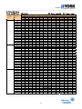
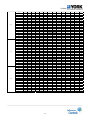
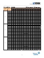
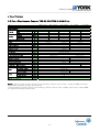
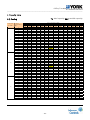
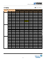
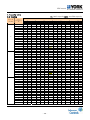
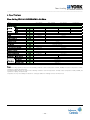
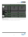
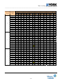
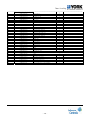
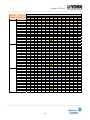
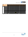
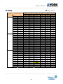
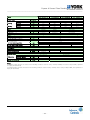
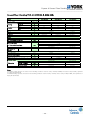
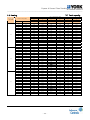
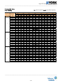
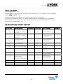
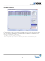
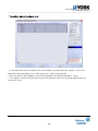
2. Capacity table
YDS-100WC15A COOLING
TC Total capacity PI Power input
Combination,
%(Capacity
index)
Outdoor
temperature(°C
DB)
10.00
100%
90%
80%
12.00
14.00
16.00
18.00
19.00
21.00
23.00
25.00
27.00
29.00
31.00
33.00
35.00
37.00
39.00
41.00
43.00
10.00
12.00
14.00
16.00
18.00
19.00
21.00
23.00
25.00
27.00
29.00
31.00
33.00
35.00
37.00
39.00
41.00
43.00
10.00
12.00
14.00
16.00
18.00
19.00
21.00
23.00
25.00
27.00
29.00
31.00
33.00
35.00
37.00
39.00
41.00
43.00
14
TC
kW
6.68
6.69
6.69
6.70
6.71
6.72
6.74
7.27
7.27
7.25
7.24
7.23
7.22
7.17
7.10
6.96
6.89
6.82
6.01
6.02
6.02
6.03
6.04
6.05
6.07
6.55
6.54
6.52
6.51
6.51
6.50
6.46
6.39
6.26
6.20
6.13
5.34
5.35
5.35
5.36
5.37
5.38
5.40
5.82
5.81
5.80
5.79
5.79
5.77
5.74
5.68
5.57
5.51
5.45
16
PI
kW
2.05
2.06
2.06
2.06
2.07
2.08
2.08
2.09
2.10
2.11
2.12
2.14
2.15
2.22
2.37
2.38
2.39
2.40
1.78
1.78
1.78
1.78
1.79
1.80
1.80
1.81
1.82
1.83
1.84
1.85
1.86
1.92
2.05
2.05
2.06
2.07
1.52
1.52
1.52
1.52
1.53
1.54
1.54
1.54
1.55
1.56
1.57
1.58
1.59
1.64
1.75
1.75
1.76
1.77
TC
kW
7.88
7.89
7.90
7.91
7.92
7.94
7.96
8.59
8.58
8.55
8.55
8.54
8.52
8.47
8.38
8.22
8.13
8.05
7.10
7.10
7.11
7.12
7.13
7.14
7.17
7.73
7.72
7.70
7.69
7.68
7.67
7.62
7.55
7.39
7.32
7.24
6.31
6.31
6.32
6.33
6.34
6.35
6.37
6.87
6.86
6.84
6.84
6.83
6.82
6.78
6.71
6.57
6.50
6.44
18
PI
kW
2.56
2.56
2.56
2.57
2.58
2.59
2.60
2.61
2.62
2.63
2.65
2.66
2.67
2.77
2.95
2.96
2.97
2.99
2.21
2.21
2.22
2.22
2.23
2.24
2.25
2.25
2.26
2.28
2.29
2.30
2.31
2.40
2.55
2.56
2.57
2.58
1.89
1.89
1.89
1.90
1.90
1.91
1.92
1.92
1.93
1.94
1.95
1.97
1.98
2.05
2.18
2.19
2.20
2.21
TC
kW
9.09
9.10
9.11
9.12
9.13
9.15
9.18
9.90
9.89
9.86
9.85
9.84
9.82
9.76
9.67
9.47
9.37
9.28
8.18
8.19
8.20
8.21
8.22
8.23
8.26
8.91
8.90
8.88
8.87
8.86
8.84
8.79
8.70
8.52
8.44
8.35
7.27
7.28
7.29
7.30
7.30
7.32
7.34
7.92
7.91
7.89
7.88
7.87
7.86
7.81
7.73
7.58
7.50
7.42
PI
kW
3.06
3.07
3.07
3.08
3.09
3.10
3.11
3.12
3.14
3.15
3.17
3.19
3.20
3.32
3.53
3.55
3.56
3.58
2.65
2.65
2.65
2.66
2.67
2.68
2.69
2.70
2.71
2.73
2.74
2.75
2.77
2.87
3.05
3.07
3.08
3.09
2.26
2.26
2.27
2.27
2.28
2.29
2.30
2.30
2.32
2.33
2.34
2.35
2.37
2.45
2.61
2.62
2.63
2.64
Indoor temperature(°CWB)
19
20
TC
PI
TC
PI
kW
kW
kW
kW
9.65
3.32
10.19
3.58
9.66
3.33
10.21
3.59
9.67
3.33
10.22
3.59
9.68
3.34
10.23
3.60
9.69
3.35
10.24
3.61
9.71
3.37
10.26
3.63
9.74
3.37
10.29
3.64
10.51
3.38
11.10
3.65
10.49
3.40
11.09
3.67
10.46
3.42
11.06
3.69
10.45
3.44
11.05
3.71
10.44
3.46
11.04
3.73
10.42
3.47
11.02
3.74
10.36
3.60
10.95
3.88
10.26
3.83
10.84
4.13
10.05
3.85
10.62
4.15
9.95
3.86
10.51
4.16
9.84
3.88
10.40
4.18
8.68
2.87
9.18
3.10
8.69
2.88
9.19
3.10
8.70
2.88
9.20
3.10
8.71
2.89
9.21
3.11
8.72
2.89
9.21
3.12
8.74
2.91
9.23
3.14
8.76
2.92
9.26
3.14
9.45
2.93
9.99
3.15
9.45
2.94
9.98
3.17
9.42
2.96
9.95
3.19
9.41
2.97
9.94
3.20
9.40
2.99
9.93
3.22
9.38
3.00
9.91
3.24
9.32
3.11
9.86
3.35
9.23
3.31
9.76
3.57
9.04
3.32
9.56
3.58
8.95
3.34
9.46
3.60
8.86
3.35
9.36
3.62
7.72
2.45
8.16
2.65
7.72
2.46
8.16
2.65
7.73
2.46
8.17
2.65
7.74
2.47
8.18
2.66
7.75
2.47
8.19
2.67
7.77
2.49
8.21
2.68
7.79
2.49
8.23
2.69
8.40
2.50
8.88
2.69
8.40
2.51
8.87
2.71
8.37
2.53
8.85
2.72
8.36
2.54
8.84
2.74
8.35
2.55
8.83
2.75
8.34
2.57
8.81
2.77
8.29
2.66
8.76
2.87
8.21
2.83
8.67
3.05
8.04
2.84
8.50
3.06
7.96
2.85
8.41
3.07
7.87
2.87
8.32
3.09
22
TC
kW
10.42
10.43
10.44
10.46
10.47
10.49
10.52
11.35
11.34
11.31
11.29
11.28
11.26
11.19
11.08
10.86
10.75
10.63
9.38
9.39
9.40
9.41
9.42
9.44
9.47
10.22
10.21
10.18
10.17
10.16
10.14
10.07
9.97
9.77
9.67
9.57
8.34
8.35
8.36
8.36
8.37
8.39
8.42
9.08
9.07
9.04
9.04
9.03
9.01
8.96
8.87
8.69
8.60
8.51
24
PI
kW
3.59
3.60
3.60
3.61
3.62
3.64
3.65
3.66
3.68
3.70
3.72
3.74
3.76
3.89
4.14
4.16
4.18
4.20
3.11
3.11
3.11
3.12
3.13
3.15
3.15
3.16
3.18
3.20
3.21
3.23
3.25
3.37
3.58
3.59
3.61
3.63
2.65
2.66
2.66
2.67
2.67
2.69
2.69
2.70
2.72
2.73
2.75
2.76
2.77
2.87
3.06
3.07
3.08
3.10
TC
kW
10.64
10.65
10.67
10.68
10.69
10.71
10.75
11.59
11.58
11.55
11.54
11.52
11.50
11.43
11.32
11.09
10.97
10.86
9.58
9.59
9.60
9.61
9.62
9.64
9.67
10.43
10.42
10.39
10.38
10.37
10.35
10.29
10.19
9.98
9.88
9.77
8.51
8.52
8.53
8.54
8.55
8.57
8.60
9.27
9.26
9.24
9.23
9.22
9.20
9.15
9.05
8.87
8.78
8.69
PI
kW
3.63
3.63
3.64
3.65
3.66
3.67
3.68
3.69
3.71
3.73
3.75
3.77
3.79
3.93
4.18
4.20
4.22
4.24
3.14
3.14
3.14
3.15
3.16
3.18
3.18
3.19
3.21
3.23
3.24
3.26
3.28
3.40
3.61
3.63
3.65
3.66
2.68
2.68
2.68
2.69
2.70
2.71
2.72
2.73
2.74
2.76
2.77
2.79
2.80
2.90
3.09
3.10
3.11
3.13
___________________________________________________________________________________
- 29 -
Outdoor
___________________________________________________________________________________
10.00
70%
60%
50%
12.00
14.00
16.00
18.00
19.00
21.00
23.00
25.00
27.00
29.00
31.00
33.00
35.00
37.00
39.00
41.00
43.00
10.00
12.00
14.00
16.00
18.00
19.00
21.00
23.00
25.00
27.00
29.00
31.00
33.00
35.00
37.00
39.00
41.00
43.00
10.00
12.00
14.00
16.00
18.00
19.00
21.00
23.00
25.00
27.00
29.00
31.00
33.00
35.00
37.00
39.00
41.00
43.00
4.68
4.68
4.69
4.69
4.70
4.71
4.72
5.09
5.09
5.07
5.07
5.06
5.05
5.02
4.97
4.87
4.82
4.77
4.01
4.01
4.02
4.02
4.02
4.03
4.05
4.36
4.36
4.35
4.34
4.34
4.33
4.30
4.26
4.18
4.13
4.09
3.34
3.34
3.35
3.35
3.35
3.36
3.37
3.64
3.63
3.62
3.62
3.62
3.61
3.59
3.55
3.48
3.44
3.41
1.28
1.28
1.28
1.28
1.29
1.29
1.30
1.30
1.31
1.31
1.32
1.33
1.34
1.38
1.47
1.48
1.48
1.49
1.06
1.06
1.06
1.06
1.06
1.07
1.07
1.08
1.08
1.09
1.09
1.10
1.11
1.15
1.22
1.22
1.23
1.23
0.86
0.86
0.86
0.86
0.86
0.87
0.87
0.87
0.88
0.88
0.89
0.89
0.90
0.93
0.99
0.99
1.00
1.00
5.52
5.53
5.53
5.54
5.54
5.56
5.57
6.01
6.01
5.99
5.98
5.98
5.96
5.93
5.87
5.75
5.69
5.63
4.73
4.74
4.74
4.75
4.75
4.76
4.78
5.15
5.15
5.13
5.13
5.12
5.11
5.08
5.03
4.93
4.88
4.83
3.94
3.95
3.95
3.96
3.96
3.97
3.98
4.29
4.29
4.28
4.27
4.27
4.26
4.23
4.19
4.11
4.07
4.02
1.59
1.59
1.59
1.60
1.60
1.61
1.62
1.62
1.63
1.64
1.65
1.65
1.66
1.72
1.83
1.84
1.85
1.86
1.32
1.32
1.32
1.32
1.33
1.33
1.34
1.34
1.35
1.36
1.36
1.37
1.38
1.43
1.52
1.52
1.53
1.54
1.07
1.07
1.07
1.07
1.08
1.08
1.08
1.09
1.09
1.10
1.10
1.11
1.12
1.16
1.23
1.23
1.24
1.25
6.36
6.37
6.38
6.38
6.39
6.40
6.42
6.93
6.92
6.90
6.90
6.89
6.88
6.84
6.77
6.63
6.56
6.49
5.45
5.46
5.47
5.47
5.48
5.49
5.51
5.94
5.93
5.92
5.91
5.91
5.89
5.86
5.80
5.68
5.62
5.57
4.55
4.55
4.56
4.56
4.56
4.57
4.59
4.95
4.95
4.93
4.93
4.92
4.91
4.88
4.83
4.74
4.69
4.64
1.91
1.91
1.91
1.92
1.92
1.93
1.93
1.94
1.95
1.96
1.97
1.98
1.99
2.06
2.20
2.20
2.21
2.23
1.58
1.58
1.58
1.59
1.59
1.60
1.60
1.61
1.61
1.62
1.63
1.64
1.65
1.71
1.82
1.82
1.83
1.84
1.28
1.28
1.28
1.28
1.29
1.29
1.30
1.30
1.31
1.31
1.32
1.33
1.34
1.38
1.47
1.48
1.49
1.49
6.75
6.76
6.77
6.77
6.78
6.80
6.82
7.35
7.35
7.32
7.32
7.31
7.30
7.25
7.18
7.03
6.96
6.89
5.79
5.79
5.80
5.81
5.81
5.82
5.84
6.30
6.30
6.28
6.27
6.27
6.25
6.22
6.15
6.03
5.97
5.91
4.82
4.83
4.83
4.84
4.84
4.85
4.87
5.25
5.25
5.23
5.23
5.22
5.21
5.18
5.13
5.02
4.97
4.92
2.07
2.07
2.07
2.08
2.08
2.09
2.10
2.10
2.12
2.13
2.14
2.15
2.16
2.24
2.38
2.39
2.40
2.41
1.71
1.71
1.71
1.72
1.72
1.73
1.74
1.74
1.75
1.76
1.77
1.78
1.79
1.85
1.97
1.98
1.99
2.00
1.39
1.39
1.39
1.39
1.40
1.40
1.41
1.41
1.42
1.43
1.43
1.44
1.45
1.50
1.60
1.60
1.61
1.62
7.14
7.14
7.15
7.16
7.17
7.18
7.21
7.77
7.77
7.74
7.73
7.73
7.71
7.67
7.59
7.44
7.36
7.28
6.12
6.12
6.13
6.14
6.14
6.16
6.18
6.66
6.66
6.64
6.63
6.62
6.61
6.57
6.50
6.37
6.31
6.24
5.10
5.10
5.11
5.11
5.12
5.13
5.15
5.55
5.55
5.53
5.52
5.52
5.51
5.48
5.42
5.31
5.26
5.20
2.23
2.23
2.23
2.24
2.24
2.26
2.26
2.27
2.28
2.29
2.30
2.32
2.33
2.41
2.57
2.58
2.59
2.60
1.84
1.85
1.85
1.85
1.86
1.87
1.87
1.88
1.89
1.90
1.91
1.92
1.93
2.00
2.12
2.13
2.14
2.15
1.49
1.50
1.50
1.50
1.51
1.51
1.52
1.52
1.53
1.54
1.55
1.55
1.56
1.62
1.72
1.73
1.74
1.74
7.30
7.30
7.31
7.32
7.33
7.34
7.37
7.95
7.94
7.91
7.91
7.90
7.88
7.84
7.76
7.60
7.52
7.44
6.25
6.26
6.27
6.27
6.28
6.29
6.31
6.81
6.80
6.78
6.78
6.77
6.76
6.72
6.65
6.51
6.45
6.38
5.21
5.22
5.22
5.23
5.23
5.24
5.26
5.68
5.67
5.65
5.65
5.64
5.63
5.60
5.54
5.43
5.37
5.32
2.23
2.24
2.24
2.25
2.25
2.26
2.27
2.28
2.29
2.30
2.31
2.32
2.34
2.42
2.57
2.59
2.60
2.61
1.85
1.85
1.85
1.86
1.86
1.87
1.88
1.88
1.89
1.90
1.91
1.92
1.93
2.00
2.13
2.14
2.15
2.16
1.50
1.50
1.50
1.51
1.51
1.52
1.52
1.53
1.53
1.54
1.55
1.56
1.57
1.62
1.73
1.73
1.74
1.75
7.45
7.46
7.47
7.47
7.48
7.50
7.52
8.11
8.11
8.08
8.07
8.07
8.05
8.00
7.92
7.76
7.68
7.60
6.39
6.39
6.40
6.41
6.41
6.43
6.45
6.96
6.95
6.93
6.92
6.91
6.90
6.86
6.79
6.65
6.58
6.52
5.32
5.33
5.33
5.34
5.34
5.36
5.37
5.80
5.79
5.77
5.77
5.76
5.75
5.72
5.66
5.54
5.49
5.43
2.26
2.26
2.26
2.27
2.27
2.29
2.29
2.30
2.31
2.32
2.33
2.35
2.36
2.44
2.60
2.61
2.62
2.63
1.87
1.87
1.87
1.88
1.88
1.89
1.90
1.90
1.91
1.92
1.93
1.94
1.95
2.02
2.15
2.16
2.17
2.18
1.51
1.51
1.52
1.52
1.52
1.53
1.54
1.54
1.55
1.56
1.57
1.57
1.58
1.64
1.74
1.75
1.76
1.77
___________________________________________________________________________________
- 30 -
Outdoor
___________________________________________________________________________________
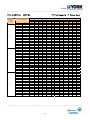
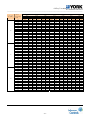
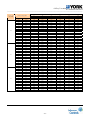
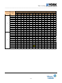
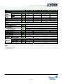
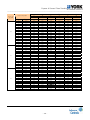
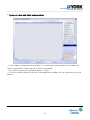
YDS-100WC35A
Combination,
%(Capacity
index)
Outdoor
temperature(°C
DB)
10.00
100%
90%
80%
12.00
14.00
16.00
18.00
19.00
21.00
23.00
25.00
27.00
29.00
31.00
33.00
35.00
37.00
39.00
41.00
43.00
10.00
12.00
14.00
16.00
18.00
19.00
21.00
23.00
25.00
27.00
29.00
31.00
33.00
35.00
37.00
39.00
41.00
43.00
10.00
12.00
14.00
16.00
18.00
19.00
21.00
23.00
25.00
27.00
29.00
31.00
33.00
35.00
37.00
39.00
41.00
43.00
COOLING
TC Total capacity PI Power input
14
TC
kW
6.44
6.45
6.45
6.46
6.47
6.48
6.50
7.01
7.01
6.99
6.98
6.97
6.96
6.92
6.85
6.71
6.64
6.57
5.80
5.80
5.81
5.82
5.82
5.83
5.85
6.31
6.31
6.29
6.28
6.28
6.26
6.23
6.16
6.04
5.98
5.91
5.15
5.16
5.16
5.17
5.17
5.19
5.20
5.61
5.61
5.59
5.58
5.58
5.57
5.53
5.48
5.37
5.31
5.26
16
PI
kW
2.00
2.00
2.00
2.01
2.01
2.02
2.03
2.03
2.04
2.05
2.07
2.08
2.09
2.16
2.30
2.31
2.32
2.33
1.73
1.73
1.73
1.74
1.74
1.75
1.75
1.76
1.77
1.78
1.79
1.80
1.80
1.87
1.99
2.00
2.01
2.02
1.47
1.48
1.48
1.48
1.49
1.49
1.50
1.50
1.51
1.52
1.53
1.53
1.54
1.60
1.70
1.71
1.71
1.72
TC
kW
7.60
7.61
7.62
7.63
7.64
7.65
7.68
8.28
8.27
8.25
8.24
8.23
8.22
8.17
8.09
7.92
7.84
7.76
6.84
6.85
6.86
6.87
6.87
6.89
6.91
7.45
7.45
7.42
7.42
7.41
7.39
7.35
7.28
7.13
7.06
6.98
6.08
6.09
6.10
6.10
6.11
6.12
6.14
6.62
6.62
6.60
6.59
6.59
6.57
6.53
6.47
6.34
6.27
6.21
18
PI
kW
2.49
2.49
2.49
2.50
2.51
2.52
2.53
2.53
2.55
2.56
2.57
2.59
2.60
2.70
2.87
2.88
2.89
2.91
2.15
2.15
2.16
2.16
2.17
2.18
2.18
2.19
2.20
2.21
2.22
2.24
2.25
2.33
2.48
2.49
2.50
2.51
1.84
1.84
1.84
1.85
1.85
1.86
1.86
1.87
1.88
1.89
1.90
1.91
1.92
1.99
2.12
2.13
2.14
2.15
TC
kW
8.77
8.78
8.78
8.79
8.80
8.82
8.85
9.55
9.54
9.51
9.50
9.49
9.47
9.42
9.32
9.13
9.04
8.94
7.89
7.90
7.91
7.91
7.92
7.94
7.97
8.59
8.58
8.56
8.55
8.54
8.52
8.47
8.39
8.22
8.14
8.05
7.01
7.02
7.03
7.04
7.04
7.06
7.08
7.64
7.63
7.61
7.60
7.59
7.58
7.53
7.46
7.31
7.23
7.16
PI
kW
2.98
2.98
2.98
2.99
3.00
3.02
3.02
3.03
3.05
3.07
3.08
3.10
3.11
3.23
3.43
3.45
3.46
3.48
2.57
2.58
2.58
2.59
2.59
2.61
2.61
2.62
2.64
2.65
2.66
2.68
2.69
2.79
2.97
2.98
2.99
3.01
2.20
2.20
2.20
2.21
2.22
2.23
2.23
2.24
2.25
2.26
2.28
2.29
2.30
2.38
2.53
2.55
2.56
2.57
Indoor temperature(°CWB)
19
20
TC
PI
TC
PI
kW
kW
kW
kW
9.30
3.23
9.83
3.48
9.31
3.23
9.84
3.49
9.32
3.24
9.85
3.49
9.33
3.25
9.86
3.50
9.34
3.26
9.87
3.51
9.36
3.27
9.89
3.53
9.39
3.28
9.93
3.54
10.13
3.29
10.71
3.55
10.12
3.31
10.70
3.57
10.09
3.33
10.67
3.58
10.08
3.34
10.65
3.60
10.07
3.36
10.64
3.62
10.05
3.38
10.62
3.64
9.99
3.50
10.56
3.77
9.89
3.72
10.45
4.01
9.69
3.74
10.24
4.03
9.59
3.76
10.14
4.05
9.49
3.77
10.03
4.07
8.37
2.79
8.85
3.01
8.38
2.80
8.86
3.01
8.39
2.80
8.87
3.02
8.40
2.81
8.88
3.03
8.41
2.81
8.89
3.03
8.42
2.83
8.90
3.05
8.45
2.84
8.93
3.06
9.12
2.84
9.64
3.07
9.11
2.86
9.63
3.08
9.08
2.87
9.60
3.10
9.07
2.89
9.59
3.11
9.06
2.90
9.58
3.13
9.04
2.92
9.56
3.15
8.99
3.03
9.50
3.26
8.90
3.22
9.41
3.47
8.72
3.23
9.22
3.48
8.63
3.25
9.12
3.50
8.54
3.26
9.03
3.52
7.44
2.39
7.86
2.57
7.45
2.39
7.87
2.57
7.46
2.39
7.88
2.58
7.46
2.40
7.89
2.59
7.47
2.40
7.90
2.59
7.49
2.42
7.92
2.61
7.51
2.42
7.94
2.61
8.10
2.43
8.57
2.62
8.10
2.44
8.56
2.63
8.07
2.46
8.53
2.65
8.06
2.47
8.52
2.66
8.06
2.48
8.52
2.67
8.04
2.49
8.50
2.69
7.99
2.58
8.45
2.79
7.91
2.75
8.36
2.96
7.75
2.76
8.19
2.98
7.67
2.77
8.11
2.99
7.59
2.79
8.03
3.00
22
TC
kW
10.05
10.06
10.07
10.08
10.09
10.11
10.15
10.95
10.93
10.90
10.89
10.88
10.86
10.79
10.69
10.47
10.36
10.25
9.04
9.05
9.06
9.07
9.08
9.10
9.13
9.85
9.84
9.81
9.80
9.79
9.77
9.71
9.62
9.42
9.33
9.23
8.04
8.05
8.06
8.07
8.07
8.09
8.12
8.76
8.75
8.72
8.71
8.70
8.69
8.64
8.55
8.38
8.29
8.20
24
PI
kW
3.49
3.50
3.50
3.51
3.52
3.54
3.55
3.56
3.58
3.60
3.61
3.63
3.65
3.78
4.03
4.04
4.06
4.08
3.02
3.02
3.03
3.04
3.04
3.06
3.07
3.08
3.09
3.11
3.12
3.14
3.16
3.27
3.48
3.49
3.51
3.53
2.58
2.58
2.59
2.59
2.60
2.61
2.62
2.63
2.64
2.65
2.67
2.68
2.70
2.79
2.97
2.99
3.00
3.01
TC
kW
10.26
10.27
10.29
10.30
10.31
10.33
10.36
11.18
11.17
11.13
11.12
11.11
11.09
11.02
10.91
10.69
10.58
10.47
9.24
9.25
9.26
9.27
9.28
9.30
9.33
10.06
10.05
10.02
10.01
10.00
9.98
9.92
9.82
9.62
9.52
9.43
8.21
8.22
8.23
8.24
8.25
8.26
8.29
8.94
8.93
8.91
8.90
8.89
8.87
8.82
8.73
8.55
8.47
8.38
PI
kW
3.53
3.53
3.53
3.55
3.55
3.57
3.58
3.59
3.61
3.63
3.65
3.67
3.69
3.82
4.06
4.08
4.10
4.12
3.05
3.05
3.06
3.07
3.07
3.09
3.10
3.11
3.12
3.14
3.15
3.17
3.19
3.30
3.51
3.53
3.54
3.56
2.60
2.61
2.61
2.62
2.62
2.64
2.64
2.65
2.67
2.68
2.69
2.71
2.72
2.82
3.00
3.01
3.03
3.04
___________________________________________________________________________________
- 31 -
Outdoor
___________________________________________________________________________________
10.00
70%
60%
50%
12.00
14.00
16.00
18.00
19.00
21.00
23.00
25.00
27.00
29.00
31.00
33.00
35.00
37.00
39.00
41.00
43.00
10.00
12.00
14.00
16.00
18.00
19.00
21.00
23.00
25.00
27.00
29.00
31.00
33.00
35.00
37.00
39.00
41.00
43.00
10.00
12.00
14.00
16.00
18.00
19.00
21.00
23.00
25.00
27.00
29.00
31.00
33.00
35.00
37.00
39.00
41.00
43.00
4.51
4.51
4.52
4.52
4.53
4.54
4.55
4.91
4.91
4.89
4.89
4.88
4.87
4.84
4.79
4.70
4.65
4.60
3.86
3.87
3.87
3.88
3.88
3.89
3.90
4.21
4.20
4.19
4.19
4.18
4.18
4.15
4.11
4.03
3.98
3.94
3.22
3.22
3.23
3.23
3.23
3.24
3.25
3.51
3.50
3.49
3.49
3.49
3.48
3.46
3.42
3.36
3.32
3.29
1.24
1.24
1.24
1.25
1.25
1.26
1.26
1.26
1.27
1.28
1.28
1.29
1.30
1.35
1.43
1.44
1.44
1.45
1.03
1.03
1.03
1.03
1.04
1.04
1.04
1.05
1.05
1.06
1.06
1.07
1.07
1.11
1.18
1.19
1.19
1.20
0.83
0.83
0.83
0.84
0.84
0.84
0.85
0.85
0.85
0.86
0.86
0.87
0.87
0.90
0.96
0.96
0.97
0.97
5.32
5.33
5.33
5.34
5.35
5.36
5.37
5.80
5.79
5.77
5.77
5.76
5.75
5.72
5.66
5.55
5.49
5.43
4.56
4.57
4.57
4.58
4.58
4.59
4.61
4.97
4.96
4.95
4.94
4.94
4.93
4.90
4.85
4.75
4.70
4.66
3.80
3.81
3.81
3.81
3.82
3.83
3.84
4.14
4.14
4.12
4.12
4.12
4.11
4.08
4.04
3.96
3.92
3.88
1.55
1.55
1.55
1.56
1.56
1.57
1.57
1.58
1.58
1.59
1.60
1.61
1.62
1.68
1.78
1.79
1.80
1.81
1.28
1.28
1.28
1.29
1.29
1.30
1.30
1.30
1.31
1.32
1.32
1.33
1.34
1.39
1.48
1.48
1.49
1.50
1.04
1.04
1.04
1.04
1.05
1.05
1.05
1.06
1.06
1.07
1.07
1.08
1.08
1.12
1.20
1.20
1.21
1.21
6.14
6.14
6.15
6.16
6.16
6.18
6.20
6.68
6.68
6.66
6.65
6.64
6.63
6.59
6.52
6.39
6.33
6.26
5.26
5.27
5.27
5.28
5.28
5.29
5.31
5.73
5.72
5.71
5.70
5.69
5.68
5.65
5.59
5.48
5.42
5.37
4.38
4.39
4.39
4.40
4.40
4.41
4.43
4.77
4.77
4.75
4.75
4.75
4.74
4.71
4.66
4.57
4.52
4.47
1.85
1.85
1.86
1.86
1.87
1.88
1.88
1.89
1.90
1.91
1.92
1.93
1.94
2.01
2.13
2.14
2.15
2.16
1.53
1.53
1.54
1.54
1.54
1.55
1.56
1.56
1.57
1.58
1.59
1.59
1.60
1.66
1.77
1.77
1.78
1.79
1.24
1.24
1.24
1.25
1.25
1.26
1.26
1.26
1.27
1.28
1.29
1.29
1.30
1.35
1.43
1.44
1.44
1.45
6.51
6.52
6.52
6.53
6.54
6.55
6.57
7.09
7.08
7.06
7.06
7.05
7.03
6.99
6.92
6.78
6.71
6.64
5.58
5.59
5.59
5.60
5.60
5.62
5.63
6.08
6.07
6.05
6.05
6.04
6.03
5.99
5.93
5.81
5.75
5.69
4.65
4.66
4.66
4.67
4.67
4.68
4.70
5.06
5.06
5.04
5.04
5.03
5.02
5.00
4.95
4.85
4.80
4.75
2.01
2.01
2.01
2.02
2.02
2.04
2.04
2.05
2.06
2.07
2.08
2.09
2.10
2.18
2.31
2.32
2.34
2.35
1.66
1.66
1.67
1.67
1.68
1.68
1.69
1.69
1.70
1.71
1.72
1.73
1.74
1.80
1.92
1.92
1.93
1.94
1.35
1.35
1.35
1.35
1.36
1.36
1.37
1.37
1.38
1.39
1.39
1.40
1.41
1.46
1.55
1.56
1.57
1.57
6.88
6.89
6.90
6.90
6.91
6.93
6.95
7.50
7.49
7.47
7.46
7.45
7.44
7.39
7.32
7.17
7.10
7.02
5.90
5.90
5.91
5.92
5.92
5.94
5.96
6.42
6.42
6.40
6.39
6.39
6.37
6.34
6.27
6.15
6.08
6.02
4.92
4.92
4.93
4.93
4.94
4.95
4.96
5.35
5.35
5.33
5.33
5.32
5.31
5.28
5.23
5.12
5.07
5.02
2.17
2.17
2.17
2.18
2.18
2.19
2.20
2.21
2.22
2.23
2.24
2.25
2.26
2.35
2.50
2.51
2.52
2.53
1.79
1.79
1.80
1.80
1.81
1.82
1.82
1.83
1.84
1.84
1.85
1.86
1.87
1.94
2.07
2.07
2.08
2.09
1.45
1.45
1.46
1.46
1.46
1.47
1.47
1.48
1.49
1.49
1.50
1.51
1.52
1.57
1.67
1.68
1.69
1.70
7.03
7.04
7.05
7.06
7.06
7.08
7.10
7.66
7.65
7.63
7.62
7.62
7.60
7.56
7.48
7.33
7.25
7.18
6.03
6.04
6.04
6.05
6.06
6.07
6.09
6.57
6.56
6.54
6.53
6.53
6.52
6.48
6.41
6.28
6.22
6.15
5.02
5.03
5.04
5.04
5.05
5.06
5.07
5.47
5.47
5.45
5.45
5.44
5.43
5.40
5.34
5.24
5.18
5.13
2.17
2.17
2.18
2.18
2.19
2.20
2.21
2.21
2.22
2.24
2.25
2.26
2.27
2.35
2.50
2.51
2.53
2.54
1.80
1.80
1.80
1.81
1.81
1.82
1.83
1.83
1.84
1.85
1.86
1.87
1.88
1.95
2.07
2.08
2.09
2.10
1.46
1.46
1.46
1.46
1.47
1.48
1.48
1.48
1.49
1.50
1.51
1.52
1.52
1.58
1.68
1.69
1.69
1.70
7.18
7.19
7.20
7.21
7.22
7.23
7.25
7.82
7.82
7.79
7.79
7.78
7.76
7.72
7.64
7.49
7.41
7.33
6.16
6.16
6.17
6.18
6.18
6.20
6.22
6.71
6.70
6.68
6.67
6.67
6.65
6.61
6.55
6.42
6.35
6.28
5.13
5.14
5.14
5.15
5.15
5.16
5.18
5.59
5.58
5.57
5.56
5.56
5.55
5.51
5.46
5.35
5.29
5.24
2.19
2.20
2.20
2.21
2.21
2.22
2.23
2.23
2.25
2.26
2.27
2.28
2.29
2.38
2.53
2.54
2.55
2.56
1.82
1.82
1.82
1.83
1.83
1.84
1.84
1.85
1.86
1.87
1.88
1.89
1.90
1.97
2.09
2.10
2.11
2.12
1.47
1.47
1.47
1.48
1.48
1.49
1.49
1.50
1.51
1.51
1.52
1.53
1.54
1.59
1.69
1.70
1.71
1.72
___________________________________________________________________________________
- 32 -
Outdoor
___________________________________________________________________________________
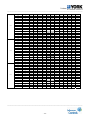
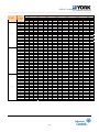
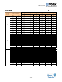
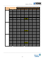
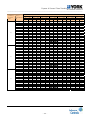
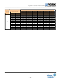
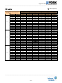
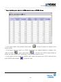
YDS-140WC15A
Combination,
%(Capacity
index)
Outdoor
temperature(°C
DB)
10.00
100%
90%
80%
12.00
14.00
16.00
18.00
19.00
21.00
23.00
25.00
27.00
29.00
31.00
33.00
35.00
37.00
39.00
41.00
43.00
10.00
12.00
14.00
16.00
18.00
19.00
21.00
23.00
25.00
27.00
29.00
31.00
33.00
35.00
37.00
39.00
41.00
43.00
10.00
12.00
14.00
16.00
18.00
19.00
21.00
23.00
25.00
27.00
29.00
31.00
33.00
35.00
37.00
39.00
41.00
43.00
COOLING
TC Total capacity PI Power input
14
TC
kW
9.06
9.07
9.08
9.09
9.10
9.12
9.15
9.87
9.86
9.83
9.82
9.81
9.79
9.74
9.64
9.44
9.35
9.25
8.16
8.17
8.18
8.18
8.19
8.21
8.24
8.89
8.88
8.85
8.84
8.83
8.82
8.76
8.68
8.50
8.41
8.32
7.25
7.26
7.27
7.28
7.28
7.30
7.32
7.90
7.89
7.87
7.86
7.85
7.84
7.79
7.71
7.56
7.48
7.40
16
PI
kW
2.41
2.42
2.42
2.43
2.43
2.44
2.45
2.46
2.47
2.48
2.50
2.51
2.52
2.61
2.78
2.79
2.80
2.82
2.09
2.09
2.09
2.10
2.10
2.11
2.12
2.12
2.14
2.15
2.16
2.17
2.18
2.26
2.40
2.41
2.42
2.44
1.78
1.78
1.79
1.79
1.80
1.80
1.81
1.81
1.82
1.83
1.84
1.85
1.86
1.93
2.05
2.06
2.07
2.08
TC
kW
10.70
10.71
10.72
10.74
10.75
10.77
10.80
11.65
11.64
11.61
11.60
11.59
11.56
11.49
11.38
11.15
11.03
10.92
9.63
9.64
9.65
9.66
9.67
9.69
9.72
10.49
10.48
10.45
10.44
10.43
10.41
10.34
10.24
10.03
9.93
9.83
8.56
8.57
8.58
8.59
8.60
8.62
8.64
9.32
9.31
9.29
9.28
9.27
9.25
9.20
9.10
8.92
8.83
8.74
PI
kW
3.01
3.01
3.01
3.02
3.03
3.05
3.05
3.06
3.08
3.09
3.11
3.13
3.14
3.26
3.46
3.48
3.49
3.51
2.60
2.60
2.60
2.61
2.62
2.63
2.64
2.65
2.66
2.67
2.69
2.70
2.72
2.82
2.99
3.01
3.02
3.04
2.22
2.22
2.22
2.23
2.24
2.25
2.25
2.26
2.27
2.28
2.30
2.31
2.32
2.41
2.56
2.57
2.58
2.59
Indoor temperature(°CWB)
18
19
20
TC
PI
TC
PI
TC
kW
kW
kW
kW
kW
12.34
3.60
13.09
3.90
13.84
12.35
3.60
13.10
3.91
13.85
12.36
3.61
13.12
3.91
13.87
12.38
3.62
13.13
3.93
13.88
12.39
3.63
13.15
3.93
13.90
12.42
3.65
13.17
3.96
13.93
12.46
3.65
13.22
3.96
13.97
13.44
3.67
14.26
3.98
15.07
13.42
3.69
14.24
4.00
15.05
13.38
3.71
14.20
4.02
15.01
13.37
3.72
14.19
4.04
15.00
13.36
3.74
14.17
4.06
14.98
13.33
3.76
14.14
4.08
14.95
13.25
3.90
14.06
4.23
14.86
13.12
4.15
13.92
4.50
14.71
12.85
4.17
13.64
4.52
14.42
12.72
4.18
13.50
4.54
14.27
12.59
4.20
13.36
4.56
14.12
11.10
3.11
11.78
3.38
12.45
11.12
3.12
11.79
3.38
12.47
11.13
3.12
11.81
3.38
12.48
11.14
3.13
11.82
3.39
12.49
11.15
3.14
11.83
3.40
12.51
11.18
3.15
11.86
3.42
12.53
11.21
3.16
11.89
3.43
12.57
12.09
3.17
12.83
3.44
13.56
12.08
3.19
12.82
3.46
13.55
12.05
3.20
12.78
3.47
13.51
12.03
3.22
12.77
3.49
13.50
12.02
3.24
12.76
3.51
13.48
12.00
3.25
12.73
3.53
13.46
11.93
3.37
12.65
3.66
13.38
11.81
3.59
12.53
3.89
13.24
11.57
3.60
12.27
3.91
12.97
11.45
3.62
12.15
3.92
12.84
11.33
3.63
12.02
3.94
12.71
9.87
2.66
10.47
2.88
11.07
9.88
2.66
10.48
2.89
11.08
9.89
2.66
10.49
2.89
11.09
9.90
2.67
10.51
2.90
11.10
9.91
2.68
10.52
2.90
11.12
9.93
2.69
10.54
2.92
11.14
9.97
2.70
10.57
2.93
11.18
10.75
2.71
11.41
2.94
12.06
10.74
2.72
11.39
2.95
12.04
10.71
2.74
11.36
2.97
12.01
10.70
2.75
11.35
2.98
12.00
10.69
2.76
11.34
3.00
11.98
10.66
2.78
11.32
3.01
11.96
10.60
2.88
11.25
3.12
11.89
10.50
3.06
11.14
3.32
11.77
10.28
3.08
10.91
3.34
11.53
10.18
3.09
10.80
3.35
11.41
10.07
3.10
10.69
3.37
11.29
22
PI
kW
4.21
4.21
4.22
4.23
4.24
4.26
4.27
4.29
4.31
4.33
4.35
4.38
4.40
4.56
4.85
4.87
4.89
4.92
3.64
3.64
3.65
3.66
3.67
3.69
3.69
3.71
3.73
3.74
3.76
3.78
3.80
3.94
4.19
4.21
4.23
4.25
3.11
3.11
3.11
3.12
3.13
3.15
3.16
3.17
3.18
3.20
3.22
3.23
3.25
3.37
3.58
3.60
3.61
3.63
TC
kW
14.14
14.16
14.17
14.19
14.20
14.23
14.28
15.40
15.39
15.34
15.33
15.31
15.28
15.19
15.04
14.74
14.58
14.43
12.73
12.74
12.76
12.77
12.78
12.81
12.85
13.86
13.85
13.81
13.80
13.78
13.75
13.67
13.54
13.26
13.13
12.99
11.31
11.33
11.34
11.35
11.36
11.39
11.42
12.32
12.31
12.27
12.26
12.25
12.23
12.15
12.03
11.79
11.67
11.55
24
PI
kW
4.22
4.23
4.23
4.24
4.25
4.28
4.29
4.30
4.32
4.35
4.37
4.39
4.41
4.57
4.86
4.89
4.91
4.93
3.65
3.65
3.66
3.67
3.68
3.70
3.71
3.72
3.74
3.76
3.78
3.80
3.82
3.95
4.21
4.22
4.24
4.26
3.12
3.12
3.12
3.13
3.14
3.16
3.16
3.17
3.19
3.21
3.23
3.24
3.26
3.38
3.59
3.61
3.62
3.64
TC
kW
14.44
14.46
14.48
14.49
14.51
14.54
14.58
15.73
15.72
15.67
15.65
15.64
15.61
15.52
15.36
15.05
14.89
14.74
13.00
13.01
13.03
13.04
13.06
13.08
13.13
14.16
14.15
14.10
14.09
14.08
14.05
13.96
13.82
13.54
13.41
13.27
11.56
11.57
11.58
11.59
11.61
11.63
11.67
12.59
12.57
12.54
12.52
12.51
12.49
12.41
12.29
12.04
11.92
11.79
PI
kW
4.26
4.27
4.27
4.29
4.30
4.32
4.33
4.34
4.36
4.39
4.41
4.43
4.46
4.62
4.91
4.93
4.96
4.98
3.69
3.69
3.69
3.71
3.71
3.73
3.74
3.75
3.77
3.79
3.81
3.83
3.85
3.99
4.25
4.26
4.28
4.30
3.15
3.15
3.15
3.16
3.17
3.19
3.20
3.21
3.22
3.24
3.26
3.27
3.29
3.41
3.63
3.64
3.66
3.68
___________________________________________________________________________________
- 33 -
Outdoor
___________________________________________________________________________________
10.00
70%
60%
50%
12.00
14.00
16.00
18.00
19.00
21.00
23.00
25.00
27.00
29.00
31.00
33.00
35.00
37.00
39.00
41.00
43.00
10.00
12.00
14.00
16.00
18.00
19.00
21.00
23.00
25.00
27.00
29.00
31.00
33.00
35.00
37.00
39.00
41.00
43.00
10.00
12.00
14.00
16.00
18.00
19.00
21.00
23.00
25.00
27.00
29.00
31.00
33.00
35.00
37.00
39.00
41.00
43.00
6.35
6.35
6.36
6.37
6.37
6.39
6.41
6.91
6.90
6.88
6.88
6.87
6.86
6.82
6.75
6.61
6.54
6.47
5.44
5.44
5.45
5.46
5.46
5.47
5.49
5.92
5.92
5.90
5.89
5.89
5.88
5.84
5.78
5.67
5.61
5.55
4.53
4.54
4.54
4.55
4.55
4.56
4.58
4.94
4.93
4.92
4.91
4.91
4.90
4.87
4.82
4.72
4.67
4.62
1.50
1.50
1.50
1.51
1.51
1.52
1.52
1.53
1.54
1.54
1.55
1.56
1.57
1.63
1.73
1.74
1.74
1.75
1.24
1.24
1.24
1.25
1.25
1.26
1.26
1.26
1.27
1.28
1.28
1.29
1.30
1.35
1.43
1.44
1.44
1.45
1.01
1.01
1.01
1.01
1.01
1.02
1.02
1.02
1.03
1.04
1.04
1.05
1.05
1.09
1.16
1.16
1.17
1.18
7.49
7.50
7.51
7.51
7.52
7.54
7.56
8.16
8.15
8.13
8.12
8.11
8.09
8.05
7.97
7.80
7.72
7.64
6.42
6.43
6.43
6.44
6.45
6.46
6.48
6.99
6.99
6.97
6.96
6.95
6.94
6.90
6.83
6.69
6.62
6.55
5.35
5.36
5.36
5.37
5.37
5.38
5.40
5.83
5.82
5.80
5.80
5.79
5.78
5.75
5.69
5.57
5.52
5.46
1.87
1.87
1.87
1.88
1.88
1.89
1.90
1.90
1.91
1.92
1.93
1.94
1.95
2.03
2.15
2.16
2.17
2.18
1.55
1.55
1.55
1.56
1.56
1.57
1.57
1.58
1.58
1.59
1.60
1.61
1.62
1.68
1.78
1.79
1.80
1.81
1.25
1.25
1.26
1.26
1.26
1.27
1.27
1.28
1.28
1.29
1.30
1.30
1.31
1.36
1.44
1.45
1.46
1.46
8.64
8.65
8.65
8.66
8.67
8.69
8.72
9.41
9.40
9.37
9.36
9.35
9.33
9.28
9.18
9.00
8.91
8.81
7.40
7.41
7.42
7.43
7.43
7.45
7.47
8.06
8.05
8.03
8.02
8.01
8.00
7.95
7.87
7.71
7.63
7.55
6.17
6.18
6.18
6.19
6.20
6.21
6.23
6.72
6.71
6.69
6.69
6.68
6.67
6.63
6.56
6.43
6.36
6.29
2.24
2.24
2.24
2.25
2.26
2.27
2.27
2.28
2.29
2.30
2.32
2.33
2.34
2.43
2.58
2.59
2.60
2.61
1.85
1.85
1.86
1.86
1.87
1.88
1.88
1.89
1.90
1.91
1.92
1.93
1.94
2.01
2.14
2.14
2.15
2.16
1.50
1.50
1.50
1.51
1.51
1.52
1.52
1.53
1.54
1.55
1.55
1.56
1.57
1.63
1.73
1.74
1.75
1.75
9.16
9.17
9.18
9.19
9.20
9.22
9.25
9.98
9.97
9.94
9.93
9.92
9.90
9.84
9.74
9.55
9.45
9.35
7.85
7.86
7.87
7.88
7.89
7.90
7.93
8.55
8.55
8.52
8.51
8.50
8.49
8.44
8.35
8.18
8.10
8.01
6.54
6.55
6.56
6.57
6.57
6.59
6.61
7.13
7.12
7.10
7.09
7.09
7.07
7.03
6.96
6.82
6.75
6.68
2.43
2.43
2.43
2.44
2.45
2.46
2.46
2.47
2.49
2.50
2.51
2.53
2.54
2.63
2.80
2.81
2.82
2.84
2.01
2.01
2.01
2.02
2.02
2.04
2.04
2.05
2.06
2.07
2.08
2.09
2.10
2.18
2.32
2.33
2.34
2.35
1.63
1.63
1.63
1.64
1.64
1.65
1.65
1.66
1.67
1.68
1.68
1.69
1.70
1.76
1.88
1.88
1.89
1.90
9.69
9.70
9.71
9.72
9.73
9.75
9.78
10.55
10.54
10.51
10.50
10.49
10.47
10.40
10.30
10.09
9.99
9.88
8.30
8.31
8.32
8.33
8.34
8.36
8.38
9.04
9.03
9.01
9.00
8.99
8.97
8.92
8.83
8.65
8.56
8.47
6.92
6.93
6.93
6.94
6.95
6.96
6.98
7.53
7.53
7.51
7.50
7.49
7.48
7.43
7.36
7.21
7.13
7.06
2.62
2.62
2.62
2.63
2.64
2.65
2.66
2.67
2.68
2.69
2.71
2.72
2.74
2.84
3.02
3.03
3.04
3.06
2.17
2.17
2.17
2.18
2.18
2.19
2.20
2.21
2.22
2.23
2.24
2.25
2.26
2.35
2.50
2.51
2.52
2.53
1.76
1.76
1.76
1.76
1.77
1.78
1.78
1.79
1.80
1.81
1.82
1.83
1.83
1.90
2.02
2.03
2.04
2.05
9.90
9.91
9.92
9.93
9.94
9.96
10.00
10.78
10.77
10.74
10.73
10.72
10.70
10.63
10.53
10.32
10.21
10.10
8.49
8.50
8.50
8.51
8.52
8.54
8.57
9.24
9.23
9.21
9.20
9.19
9.17
9.12
9.02
8.84
8.75
8.66
7.07
7.08
7.09
7.09
7.10
7.12
7.14
7.70
7.69
7.67
7.66
7.66
7.64
7.60
7.52
7.37
7.29
7.22
2.63
2.63
2.63
2.64
2.65
2.66
2.67
2.67
2.69
2.70
2.72
2.73
2.74
2.84
3.03
3.04
3.05
3.07
2.17
2.18
2.18
2.18
2.19
2.20
2.21
2.21
2.22
2.24
2.25
2.26
2.27
2.35
2.50
2.51
2.53
2.54
1.76
1.76
1.76
1.77
1.77
1.78
1.79
1.79
1.80
1.81
1.82
1.83
1.84
1.91
2.03
2.04
2.05
2.06
10.11
10.12
10.13
10.14
10.15
10.18
10.21
11.01
11.00
10.97
10.96
10.95
10.93
10.86
10.75
10.53
10.43
10.32
8.67
8.68
8.69
8.69
8.70
8.72
8.75
9.44
9.43
9.40
9.39
9.38
9.36
9.31
9.22
9.03
8.94
8.84
7.22
7.23
7.24
7.25
7.25
7.27
7.29
7.87
7.86
7.84
7.83
7.82
7.80
7.76
7.68
7.52
7.45
7.37
2.65
2.65
2.66
2.67
2.67
2.69
2.69
2.70
2.71
2.73
2.74
2.76
2.77
2.87
3.05
3.07
3.08
3.10
2.19
2.20
2.20
2.21
2.21
2.22
2.23
2.23
2.25
2.26
2.27
2.28
2.29
2.38
2.53
2.54
2.55
2.56
1.78
1.78
1.78
1.79
1.79
1.80
1.80
1.81
1.82
1.83
1.84
1.85
1.86
1.93
2.05
2.06
2.07
2.08
___________________________________________________________________________________
- 34 -
Outdoor
___________________________________________________________________________________
YDS-140WC35A
Combination,
%(Capacity
index)
Outdoor
temperature(°C
DB)
10.00
100%
90%
80%
12.00
14.00
16.00
18.00
19.00
21.00
23.00
25.00
27.00
29.00
31.00
33.00
35.00
37.00
39.00
41.00
43.00
10.00
12.00
14.00
16.00
18.00
19.00
21.00
23.00
25.00
27.00
29.00
31.00
33.00
35.00
37.00
39.00
41.00
43.00
10.00
12.00
14.00
16.00
18.00
19.00
21.00
23.00
25.00
27.00
29.00
31.00
33.00
35.00
37.00
39.00
41.00
43.00
COOLING
TC Total capacity PI Power input
14
TC
kW
9.03
9.04
9.05
9.06
9.06
9.08
9.11
9.83
9.82
9.79
9.78
9.77
9.75
9.70
9.60
9.40
9.31
9.21
8.12
8.13
8.14
8.15
8.16
8.18
8.20
8.85
8.84
8.81
8.80
8.80
8.78
8.73
8.64
8.46
8.38
8.29
7.22
7.23
7.24
7.24
7.25
7.27
7.29
7.86
7.86
7.83
7.83
7.82
7.80
7.76
7.68
7.52
7.45
7.37
16
PI
kW
2.57
2.57
2.57
2.58
2.59
2.60
2.61
2.61
2.63
2.64
2.66
2.67
2.68
2.78
2.96
2.97
2.98
3.00
2.22
2.22
2.22
2.23
2.24
2.25
2.25
2.26
2.27
2.28
2.30
2.31
2.32
2.40
2.56
2.57
2.58
2.59
1.90
1.90
1.90
1.91
1.91
1.92
1.92
1.93
1.94
1.95
1.96
1.97
1.98
2.05
2.18
2.19
2.20
2.21
TC
kW
10.66
10.67
10.68
10.69
10.70
10.72
10.76
11.61
11.59
11.56
11.55
11.54
11.51
11.45
11.33
11.10
10.99
10.87
9.59
9.60
9.61
9.62
9.63
9.65
9.68
10.44
10.43
10.40
10.39
10.38
10.36
10.30
10.20
9.99
9.89
9.79
8.52
8.53
8.54
8.55
8.56
8.58
8.61
9.28
9.28
9.25
9.24
9.23
9.21
9.16
9.06
8.88
8.79
8.70
PI
kW
3.20
3.20
3.21
3.22
3.22
3.24
3.25
3.26
3.27
3.29
3.31
3.33
3.34
3.47
3.69
3.70
3.72
3.74
2.76
2.77
2.77
2.78
2.79
2.80
2.81
2.82
2.83
2.85
2.86
2.88
2.89
3.00
3.19
3.20
3.21
3.23
2.36
2.36
2.37
2.37
2.38
2.39
2.40
2.41
2.42
2.43
2.44
2.46
2.47
2.56
2.72
2.73
2.75
2.76
Indoor temperature(°CWB)
18
19
20
TC
PI
TC
PI
TC
kW
kW
kW
kW
kW
12.28
3.83
13.03
4.15
13.78
12.30
3.83
13.05
4.16
13.79
12.31
3.84
13.06
4.16
13.81
12.32
3.85
13.08
4.18
13.82
12.34
3.86
13.09
4.19
13.84
12.36
3.88
13.12
4.21
13.87
12.40
3.89
13.16
4.22
13.91
13.38
3.90
14.20
4.23
15.01
13.37
3.92
14.18
4.25
14.99
13.33
3.94
14.14
4.28
14.95
13.31
3.96
14.13
4.30
14.93
13.30
3.98
14.11
4.32
14.92
13.27
4.00
14.08
4.34
14.89
13.20
4.15
14.00
4.50
14.80
13.06
4.41
13.86
4.79
14.65
12.80
4.43
13.58
4.81
14.35
12.67
4.45
13.44
4.83
14.21
12.54
4.47
13.30
4.85
14.06
11.06
3.31
11.73
3.59
12.40
11.07
3.31
11.74
3.59
12.41
11.08
3.32
11.76
3.60
12.43
11.09
3.33
11.77
3.61
12.44
11.10
3.34
11.78
3.62
12.45
11.13
3.35
11.81
3.64
12.48
11.16
3.36
11.84
3.65
12.52
12.04
3.37
12.78
3.66
13.50
12.03
3.39
12.76
3.68
13.49
11.99
3.41
12.73
3.70
13.45
11.98
3.43
12.71
3.72
13.44
11.97
3.44
12.70
3.73
13.42
11.95
3.46
12.68
3.75
13.40
11.88
3.59
12.60
3.89
13.32
11.76
3.81
12.47
4.14
13.19
11.52
3.83
12.22
4.16
12.92
11.40
3.85
12.10
4.17
12.79
11.28
3.87
11.97
4.19
12.65
9.83
2.83
10.43
3.07
11.02
9.84
2.83
10.44
3.07
11.03
9.85
2.83
10.45
3.07
11.05
9.86
2.84
10.46
3.08
11.06
9.87
2.85
10.47
3.09
11.07
9.89
2.86
10.49
3.11
11.09
9.92
2.87
10.53
3.11
11.13
10.70
2.88
11.36
3.12
12.00
10.69
2.90
11.35
3.14
11.99
10.66
2.91
11.31
3.16
11.96
10.65
2.93
11.30
3.17
11.94
10.64
2.94
11.29
3.19
11.93
10.62
2.96
11.27
3.21
11.91
10.56
3.06
11.20
3.32
11.84
10.45
3.26
11.09
3.53
11.72
10.24
3.27
10.86
3.55
11.48
10.13
3.29
10.75
3.57
11.36
10.03
3.30
10.64
3.58
11.25
22
PI
kW
4.48
4.48
4.49
4.50
4.51
4.54
4.55
4.56
4.58
4.61
4.63
4.66
4.68
4.85
5.16
5.18
5.21
5.23
3.87
3.87
3.88
3.89
3.90
3.92
3.93
3.94
3.96
3.98
4.00
4.03
4.05
4.19
4.46
4.48
4.50
4.52
3.31
3.31
3.31
3.32
3.33
3.35
3.36
3.37
3.39
3.40
3.42
3.44
3.46
3.58
3.81
3.83
3.84
3.86
TC
kW
14.08
14.10
14.11
14.13
14.14
14.17
14.22
15.34
15.32
15.28
15.26
15.25
15.22
15.13
14.98
14.67
14.52
14.37
12.67
12.69
12.70
12.72
12.73
12.76
12.80
13.80
13.79
13.75
13.74
13.72
13.70
13.61
13.48
13.21
13.07
12.93
11.27
11.28
11.29
11.30
11.31
11.34
11.38
12.27
12.26
12.22
12.21
12.20
12.17
12.10
11.98
11.74
11.62
11.50
24
PI
kW
4.49
4.50
4.50
4.52
4.53
4.55
4.56
4.57
4.60
4.62
4.65
4.67
4.70
4.87
5.18
5.20
5.22
5.25
3.88
3.89
3.89
3.90
3.91
3.93
3.94
3.95
3.98
4.00
4.02
4.04
4.06
4.21
4.47
4.49
4.51
4.53
3.32
3.32
3.32
3.33
3.34
3.36
3.37
3.38
3.40
3.41
3.43
3.45
3.47
3.59
3.82
3.84
3.86
3.87
TC
kW
14.38
14.40
14.41
14.43
14.44
14.48
14.52
15.67
15.65
15.60
15.59
15.57
15.54
15.45
15.29
14.99
14.83
14.68
12.94
12.96
12.97
12.99
13.00
13.03
13.07
14.10
14.08
14.04
14.03
14.02
13.99
13.90
13.77
13.49
13.35
13.21
11.51
11.52
11.53
11.54
11.56
11.58
11.62
12.53
12.52
12.48
12.47
12.46
12.43
12.36
12.24
11.99
11.86
11.74
PI
kW
4.53
4.54
4.54
4.56
4.57
4.59
4.60
4.62
4.64
4.67
4.69
4.72
4.74
4.91
5.23
5.25
5.27
5.30
3.92
3.92
3.93
3.94
3.95
3.97
3.98
3.99
4.01
4.04
4.06
4.08
4.10
4.25
4.52
4.54
4.56
4.58
3.35
3.35
3.36
3.37
3.37
3.39
3.40
3.41
3.43
3.45
3.46
3.48
3.50
3.63
3.86
3.88
3.89
3.91
___________________________________________________________________________________
- 35 -
Outdoor
___________________________________________________________________________________
10.00
70%
60%
50%
12.00
14.00
16.00
18.00
19.00
21.00
23.00
25.00
27.00
29.00
31.00
33.00
35.00
37.00
39.00
41.00
43.00
10.00
12.00
14.00
16.00
18.00
19.00
21.00
23.00
25.00
27.00
29.00
31.00
33.00
35.00
37.00
39.00
41.00
43.00
10.00
12.00
14.00
16.00
18.00
19.00
21.00
23.00
25.00
27.00
29.00
31.00
33.00
35.00
37.00
39.00
41.00
43.00
6.32
6.33
6.33
6.34
6.35
6.36
6.38
6.88
6.87
6.85
6.85
6.84
6.83
6.79
6.72
6.58
6.52
6.45
5.42
5.42
5.43
5.43
5.44
5.45
5.47
5.90
5.89
5.88
5.87
5.86
5.85
5.82
5.76
5.64
5.58
5.53
4.51
4.52
4.52
4.53
4.53
4.54
4.56
4.92
4.91
4.90
4.89
4.89
4.88
4.85
4.80
4.70
4.65
4.61
1.60
1.60
1.60
1.60
1.61
1.62
1.62
1.63
1.63
1.64
1.65
1.66
1.67
1.73
1.84
1.85
1.86
1.86
1.32
1.32
1.32
1.33
1.33
1.34
1.34
1.35
1.35
1.36
1.37
1.37
1.38
1.43
1.52
1.53
1.54
1.54
1.07
1.07
1.07
1.08
1.08
1.08
1.09
1.09
1.10
1.10
1.11
1.11
1.12
1.16
1.23
1.24
1.24
1.25
7.46
7.47
7.47
7.48
7.49
7.51
7.53
8.12
8.12
8.09
8.08
8.08
8.06
8.01
7.93
7.77
7.69
7.61
6.39
6.40
6.41
6.41
6.42
6.43
6.45
6.96
6.96
6.94
6.93
6.92
6.91
6.87
6.80
6.66
6.59
6.52
5.33
5.33
5.34
5.34
5.35
5.36
5.38
5.80
5.80
5.78
5.77
5.77
5.76
5.72
5.67
5.55
5.49
5.44
1.99
1.99
1.99
2.00
2.00
2.01
2.02
2.03
2.04
2.05
2.06
2.07
2.08
2.15
2.29
2.30
2.31
2.32
1.65
1.65
1.65
1.66
1.66
1.67
1.67
1.68
1.69
1.69
1.70
1.71
1.72
1.78
1.90
1.91
1.91
1.92
1.33
1.34
1.34
1.34
1.34
1.35
1.35
1.36
1.37
1.37
1.38
1.39
1.39
1.44
1.54
1.54
1.55
1.56
8.60
8.61
8.62
8.63
8.64
8.65
8.68
9.37
9.36
9.33
9.32
9.31
9.29
9.24
9.14
8.96
8.87
8.77
7.37
7.38
7.39
7.39
7.40
7.42
7.44
8.03
8.02
8.00
7.99
7.98
7.96
7.92
7.84
7.68
7.60
7.52
6.14
6.15
6.16
6.16
6.17
6.18
6.20
6.69
6.68
6.66
6.66
6.65
6.64
6.60
6.53
6.40
6.33
6.27
2.38
2.38
2.39
2.39
2.40
2.41
2.42
2.43
2.44
2.45
2.46
2.48
2.49
2.58
2.74
2.76
2.77
2.78
1.97
1.97
1.98
1.98
1.99
2.00
2.00
2.01
2.02
2.03
2.04
2.05
2.06
2.14
2.27
2.28
2.29
2.30
1.60
1.60
1.60
1.61
1.61
1.62
1.62
1.63
1.63
1.64
1.65
1.66
1.67
1.73
1.84
1.85
1.86
1.87
9.12
9.13
9.14
9.15
9.16
9.18
9.21
9.94
9.93
9.90
9.89
9.88
9.86
9.80
9.70
9.51
9.41
9.31
7.82
7.83
7.84
7.85
7.85
7.87
7.90
8.52
8.51
8.48
8.48
8.47
8.45
8.40
8.32
8.15
8.06
7.98
6.52
6.52
6.53
6.54
6.55
6.56
6.58
7.10
7.09
7.07
7.06
7.06
7.04
7.00
6.93
6.79
6.72
6.65
2.58
2.59
2.59
2.60
2.60
2.62
2.62
2.63
2.64
2.66
2.67
2.69
2.70
2.80
2.98
2.99
3.00
3.02
2.14
2.14
2.14
2.15
2.15
2.17
2.17
2.18
2.19
2.20
2.21
2.22
2.24
2.32
2.46
2.47
2.49
2.50
1.73
1.73
1.74
1.74
1.75
1.75
1.76
1.76
1.77
1.78
1.79
1.80
1.81
1.88
2.00
2.00
2.01
2.02
9.64
9.65
9.66
9.67
9.69
9.71
9.74
10.50
10.49
10.46
10.45
10.44
10.42
10.36
10.26
10.05
9.94
9.84
8.27
8.28
8.28
8.29
8.30
8.32
8.35
9.00
8.99
8.97
8.96
8.95
8.93
8.88
8.79
8.61
8.52
8.43
6.89
6.90
6.90
6.91
6.92
6.93
6.96
7.50
7.50
7.47
7.47
7.46
7.44
7.40
7.33
7.18
7.10
7.03
2.78
2.79
2.79
2.80
2.81
2.82
2.83
2.84
2.85
2.87
2.88
2.90
2.91
3.02
3.21
3.22
3.24
3.25
2.30
2.31
2.31
2.32
2.32
2.33
2.34
2.35
2.36
2.37
2.38
2.40
2.41
2.50
2.66
2.67
2.68
2.69
1.87
1.87
1.87
1.88
1.88
1.89
1.90
1.90
1.91
1.92
1.93
1.94
1.95
2.02
2.15
2.16
2.17
2.18
9.86
9.87
9.88
9.89
9.90
9.92
9.95
10.74
10.73
10.69
10.68
10.67
10.65
10.59
10.48
10.27
10.17
10.06
8.45
8.46
8.47
8.48
8.49
8.50
8.53
9.20
9.19
9.17
9.16
9.15
9.13
9.08
8.99
8.80
8.71
8.62
7.04
7.05
7.06
7.06
7.07
7.09
7.11
7.67
7.66
7.64
7.63
7.62
7.61
7.56
7.49
7.34
7.26
7.19
2.79
2.80
2.80
2.81
2.81
2.83
2.84
2.84
2.86
2.87
2.89
2.90
2.92
3.03
3.22
3.23
3.25
3.26
2.31
2.31
2.32
2.32
2.33
2.34
2.35
2.35
2.37
2.38
2.39
2.40
2.42
2.50
2.66
2.68
2.69
2.70
1.87
1.87
1.88
1.88
1.89
1.90
1.90
1.91
1.92
1.93
1.94
1.95
1.96
2.03
2.16
2.17
2.18
2.19
10.07
10.08
10.09
10.10
10.11
10.13
10.17
10.97
10.95
10.92
10.91
10.90
10.88
10.81
10.71
10.49
10.38
10.27
8.63
8.64
8.65
8.66
8.67
8.69
8.71
9.40
9.39
9.36
9.35
9.34
9.33
9.27
9.18
8.99
8.90
8.81
7.19
7.20
7.21
7.21
7.22
7.24
7.26
7.83
7.82
7.80
7.79
7.79
7.77
7.72
7.65
7.49
7.42
7.34
2.82
2.82
2.83
2.84
2.84
2.86
2.86
2.87
2.89
2.90
2.92
2.93
2.95
3.06
3.25
3.26
3.28
3.29
2.33
2.34
2.34
2.35
2.35
2.36
2.37
2.38
2.39
2.40
2.41
2.43
2.44
2.53
2.69
2.70
2.71
2.73
1.89
1.89
1.90
1.90
1.91
1.92
1.92
1.93
1.94
1.95
1.96
1.97
1.98
2.05
2.18
2.19
2.20
2.21
___________________________________________________________________________________
- 36 -
Outdoor
___________________________________________________________________________________
YDS-280WC35A
Combination,
%(Capacity
index)
100
90
80
Outdoor
temperature(°C
DB)
10
12
14
16
18
19
21
23
25
27
29
31
33
35
37
39
41
43
10
12
14
16
18
19
21
23
25
27
29
31
33
35
37
39
41
43
10
12
14
16
18
19
21
23
25
27
29
31
33
35
37
39
41
43
COOLING
TC Total capacity PI Power input
14
TC
kW
19.39
19.39
19.39
19.39
19.39
19.39
19.39
19.39
19.39
19.39
19.39
19.39
19.39
19.39
19.39
19.39
19.39
19.39
17.45
17.45
17.45
17.45
17.45
17.45
17.45
17.45
17.45
17.45
17.45
17.45
17.45
17.45
17.45
17.45
17.45
17.45
15.51
15.51
15.51
15.51
15.51
15.51
15.51
15.51
15.51
15.51
15.51
15.51
15.51
15.51
15.51
15.51
15.51
15.51
16
PI
kW
3.34
3.40
3.46
3.52
3.58
3.65
3.91
4.19
4.48
4.79
5.11
5.45
5.81
6.18
6.57
6.60
6.63
6.66
2.89
2.94
2.99
3.05
3.10
3.15
3.38
3.62
3.87
4.14
4.42
4.71
5.02
5.34
5.68
5.71
5.73
5.76
2.46
2.51
2.56
2.60
2.65
2.69
2.89
3.09
3.31
3.54
3.78
4.03
4.29
4.56
4.85
4.87
4.90
4.92
TC
kW
22.89
22.89
22.89
22.89
22.89
22.89
22.89
22.89
22.89
22.89
22.89
22.89
22.89
22.89
22.89
22.89
22.89
22.89
20.60
20.60
20.60
20.60
20.60
20.60
20.60
20.60
20.60
20.60
20.60
20.60
20.60
20.60
20.60
20.60
20.60
20.60
18.31
18.31
18.31
18.31
18.31
18.31
18.31
18.31
18.31
18.31
18.31
18.31
18.31
18.31
18.31
18.31
18.31
18.31
PI
kW
4.16
4.24
4.31
4.39
4.47
4.54
4.87
5.22
5.58
5.97
6.37
6.80
7.24
7.70
8.19
8.23
8.26
8.30
3.59
3.66
3.73
3.79
3.86
3.93
4.21
4.51
4.83
5.16
5.51
5.87
6.26
6.66
7.08
7.11
7.14
7.18
3.07
3.13
3.18
3.24
3.30
3.35
3.60
3.85
4.12
4.41
4.71
5.02
5.34
5.69
6.05
6.07
6.10
6.13
Indoor temperature(°CWB)
18
19
20
TC
PI
TC
PI
TC
PI
kW
kW
kW
kW
kW
kW
26.39
4.98
28.00
5.40
29.61
5.82
26.39
5.07
28.00
5.50
29.61
5.93
26.39
5.16
28.00
5.60
29.61
6.04
26.39
5.26
28.00
5.70
29.61
6.14
26.39
5.35
28.00
5.80
29.61
6.25
26.39
5.44
28.00
5.90
29.61
6.36
26.39
5.83
28.00
6.33
29.61
6.82
26.39
6.25
28.00
6.78
29.61
7.30
26.39
6.68
28.00
7.25
29.61
7.82
26.39
7.15
28.00
7.75
29.61
8.35
26.39
7.63
28.00
8.28
29.61
8.92
26.39
8.14
28.00
8.83
29.61
9.51
26.39
8.67
28.00
9.40
29.61
10.13
26.39
9.22
28.00
10.00
29.61
10.78
26.39
9.81
28.00
10.64
29.61
11.47
26.39
9.85
28.00
10.68
29.61
11.52
26.39
9.89
28.00
10.73
29.61
11.57
26.39
9.94
28.00
10.78
29.61
11.62
23.75
4.30
25.20
4.67
26.65
5.03
23.75
4.38
25.20
4.75
26.65
5.13
23.75
4.46
25.20
4.84
26.65
5.22
23.75
4.54
25.20
4.93
26.65
5.31
23.75
4.62
25.20
5.01
26.65
5.41
23.75
4.70
25.20
5.10
26.65
5.50
23.75
5.04
25.20
5.47
26.65
5.89
23.75
5.40
25.20
5.86
26.65
6.31
23.75
5.78
25.20
6.27
26.65
6.76
23.75
6.18
25.20
6.70
26.65
7.22
23.75
6.60
25.20
7.15
26.65
7.71
23.75
7.03
25.20
7.63
26.65
8.22
23.75
7.49
25.20
8.13
26.65
8.76
23.75
7.97
25.20
8.65
26.65
9.32
23.75
8.48
25.20
9.19
26.65
9.91
23.75
8.51
25.20
9.23
26.65
9.95
23.75
8.55
25.20
9.28
26.65
10.00
23.75
8.59
25.20
9.32
26.65
10.05
21.11
3.68
22.40
3.99
23.69
4.30
21.11
3.74
22.40
4.06
23.69
4.38
21.11
3.81
22.40
4.14
23.69
4.46
21.11
3.88
22.40
4.21
23.69
4.54
21.11
3.95
22.40
4.28
23.69
4.62
21.11
4.02
22.40
4.36
23.69
4.70
21.11
4.31
22.40
4.67
23.69
5.04
21.11
4.61
22.40
5.00
23.69
5.39
21.11
4.94
22.40
5.35
23.69
5.77
21.11
5.28
22.40
5.72
23.69
6.17
21.11
5.63
22.40
6.11
23.69
6.59
21.11
6.01
22.40
6.52
23.69
7.03
21.11
6.40
22.40
6.94
23.69
7.48
21.11
6.81
22.40
7.38
23.69
7.96
21.11
7.24
22.40
7.85
23.69
8.47
21.11
7.27
22.40
7.89
23.69
8.50
21.11
7.31
22.40
7.92
23.69
8.54
21.11
7.34
22.40
7.96
23.69
8.58
22
TC
kW
30.25
30.25
30.25
30.25
30.25
30.25
30.25
30.25
30.25
30.25
30.25
30.25
30.25
30.25
30.25
30.25
30.25
30.25
27.23
27.23
27.23
27.23
27.23
27.23
27.23
27.23
27.23
27.23
27.23
27.23
27.23
27.23
27.23
27.23
27.23
27.23
24.20
24.20
24.20
24.20
24.20
24.20
24.20
24.20
24.20
24.20
24.20
24.20
24.20
24.20
24.20
24.20
24.20
24.20
24
PI
kW
5.84
5.95
6.06
6.16
6.27
6.38
6.84
7.33
7.84
8.38
8.95
9.54
10.16
10.81
11.50
11.55
11.60
11.66
5.05
5.14
5.23
5.33
5.42
5.52
5.91
6.33
6.78
7.24
7.74
8.25
8.79
9.35
9.94
9.99
10.03
10.08
4.31
4.39
4.47
4.55
4.63
4.71
5.05
5.41
5.79
6.19
6.61
7.05
7.51
7.98
8.49
8.53
8.57
8.61
TC
kW
30.90
30.90
30.90
30.90
30.90
30.90
30.90
30.90
30.90
30.90
30.90
30.90
30.90
30.90
30.90
30.90
30.90
30.90
27.81
27.81
27.81
27.81
27.81
27.81
27.81
27.81
27.81
27.81
27.81
27.81
27.81
27.81
27.81
27.81
27.81
27.81
24.72
24.72
24.72
24.72
24.72
24.72
24.72
24.72
24.72
24.72
24.72
24.72
24.72
24.72
24.72
24.72
24.72
24.72
PI
kW
5.90
6.00
6.11
6.22
6.33
6.44
6.91
7.40
7.92
8.46
9.03
9.64
10.26
10.92
11.61
11.66
11.72
11.77
5.10
5.19
5.29
5.38
5.47
5.57
5.97
6.39
6.84
7.31
7.81
8.33
8.87
9.44
10.04
10.08
10.13
10.17
4.35
4.43
4.51
4.60
4.68
4.76
5.10
5.46
5.85
6.25
6.67
7.12
7.58
8.06
8.58
8.61
8.65
8.69
___________________________________________________________________________________
- 37 -
Outdoor
___________________________________________________________________________________
70
60
50
10
12
14
16
18
19
21
23
25
27
29
31
33
35
37
39
41
43
10
12
14
16
18
19
21
23
25
27
29
31
33
35
37
39
41
43
10
12
14
16
18
19
21
23
25
27
29
31
33
35
37
39
41
43
13.57
13.57
13.57
13.57
13.57
13.57
13.57
13.57
13.57
13.57
13.57
13.57
13.57
13.57
13.57
13.57
13.57
13.57
11.63
11.63
11.63
11.63
11.63
11.63
11.63
11.63
11.63
11.63
11.63
11.63
11.63
11.63
11.63
11.63
11.63
11.63
9.70
9.70
9.70
9.70
9.70
9.70
9.70
9.70
9.70
9.70
9.70
9.70
9.70
9.70
9.70
9.70
9.70
9.70
2.08
2.11
2.15
2.19
2.23
2.27
2.43
2.60
2.79
2.98
3.18
3.39
3.61
3.84
4.09
4.11
4.12
4.14
1.72
1.75
1.78
1.81
1.84
1.88
2.01
2.16
2.31
2.47
2.63
2.81
2.99
3.18
3.38
3.40
3.41
3.43
1.39
1.42
1.44
1.47
1.49
1.52
1.63
1.75
1.87
2.00
2.13
2.27
2.42
2.58
2.74
2.75
2.77
2.78
16.02
16.02
16.02
16.02
16.02
16.02
16.02
16.02
16.02
16.02
16.02
16.02
16.02
16.02
16.02
16.02
16.02
16.02
13.73
13.73
13.73
13.73
13.73
13.73
13.73
13.73
13.73
13.73
13.73
13.73
13.73
13.73
13.73
13.73
13.73
13.73
11.45
11.45
11.45
11.45
11.45
11.45
11.45
11.45
11.45
11.45
11.45
11.45
11.45
11.45
11.45
11.45
11.45
11.45
2.59
2.63
2.68
2.73
2.78
2.83
3.03
3.24
3.47
3.71
3.96
4.23
4.50
4.79
5.09
5.11
5.14
5.16
2.14
2.18
2.22
2.26
2.30
2.34
2.51
2.69
2.87
3.07
3.28
3.50
3.73
3.96
4.22
4.23
4.25
4.27
1.73
1.77
1.80
1.83
1.86
1.89
2.03
2.18
2.33
2.49
2.66
2.83
3.02
3.21
3.42
3.43
3.45
3.46
18.47
18.47
18.47
18.47
18.47
18.47
18.47
18.47
18.47
18.47
18.47
18.47
18.47
18.47
18.47
18.47
18.47
18.47
15.83
15.83
15.83
15.83
15.83
15.83
15.83
15.83
15.83
15.83
15.83
15.83
15.83
15.83
15.83
15.83
15.83
15.83
13.20
13.20
13.20
13.20
13.20
13.20
13.20
13.20
13.20
13.20
13.20
13.20
13.20
13.20
13.20
13.20
13.20
13.20
3.10
3.15
3.21
3.27
3.33
3.38
3.63
3.88
4.16
4.44
4.74
5.06
5.39
5.73
6.10
6.12
6.15
6.18
2.56
2.61
2.66
2.70
2.75
2.80
3.00
3.22
3.44
3.68
3.93
4.19
4.46
4.75
5.05
5.07
5.09
5.12
2.08
2.11
2.15
2.19
2.23
2.27
2.43
2.60
2.79
2.98
3.18
3.39
3.61
3.84
4.09
4.11
4.13
4.14
19.60
19.60
19.60
19.60
19.60
19.60
19.60
19.60
19.60
19.60
19.60
19.60
19.60
19.60
19.60
19.60
19.60
19.60
16.80
16.80
16.80
16.80
16.80
16.80
16.80
16.80
16.80
16.80
16.80
16.80
16.80
16.80
16.80
16.80
16.80
16.80
14.00
14.00
14.00
14.00
14.00
14.00
14.00
14.00
14.00
14.00
14.00
14.00
14.00
14.00
14.00
14.00
14.00
14.00
3.36
3.42
3.48
3.54
3.61
3.67
3.93
4.21
4.51
4.82
5.15
5.49
5.85
6.22
6.61
6.64
6.67
6.70
2.78
2.83
2.88
2.93
2.99
3.04
3.26
3.49
3.73
3.99
4.26
4.54
4.84
5.15
5.47
5.50
5.52
5.55
2.25
2.29
2.34
2.38
2.42
2.46
2.64
2.83
3.02
3.23
3.45
3.68
3.92
4.17
4.44
4.45
4.47
4.50
20.73
20.73
20.73
20.73
20.73
20.73
20.73
20.73
20.73
20.73
20.73
20.73
20.73
20.73
20.73
20.73
20.73
20.73
17.77
17.77
17.77
17.77
17.77
17.77
17.77
17.77
17.77
17.77
17.77
17.77
17.77
17.77
17.77
17.77
17.77
17.77
14.81
14.81
14.81
14.81
14.81
14.81
14.81
14.81
14.81
14.81
14.81
14.81
14.81
14.81
14.81
14.81
14.81
14.81
3.62
3.69
3.75
3.82
3.89
3.96
4.24
4.54
4.86
5.20
5.55
5.92
6.30
6.70
7.13
7.16
7.19
7.23
3.00
3.05
3.11
3.16
3.22
3.27
3.51
3.76
4.02
4.30
4.59
4.90
5.22
5.55
5.90
5.93
5.95
5.98
2.43
2.47
2.52
2.56
2.61
2.65
2.84
3.05
3.26
3.48
3.72
3.97
4.23
4.50
4.78
4.80
4.82
4.85
21.18
21.18
21.18
21.18
21.18
21.18
21.18
21.18
21.18
21.18
21.18
21.18
21.18
21.18
21.18
21.18
21.18
21.18
18.15
18.15
18.15
18.15
18.15
18.15
18.15
18.15
18.15
18.15
18.15
18.15
18.15
18.15
18.15
18.15
18.15
18.15
15.13
15.13
15.13
15.13
15.13
15.13
15.13
15.13
15.13
15.13
15.13
15.13
15.13
15.13
15.13
15.13
15.13
15.13
3.63
3.70
3.77
3.83
3.90
3.97
4.25
4.56
4.87
5.21
5.56
5.93
6.32
6.72
7.15
7.18
7.21
7.25
3.01
3.06
3.12
3.17
3.23
3.28
3.52
3.77
4.03
4.31
4.61
4.91
5.23
5.57
5.92
5.95
5.97
6.00
2.43
2.48
2.53
2.57
2.62
2.66
2.85
3.05
3.27
3.49
3.73
3.98
4.24
4.51
4.80
4.82
4.84
4.86
21.63
21.63
21.63
21.63
21.63
21.63
21.63
21.63
21.63
21.63
21.63
21.63
21.63
21.63
21.63
21.63
21.63
21.63
18.54
18.54
18.54
18.54
18.54
18.54
18.54
18.54
18.54
18.54
18.54
18.54
18.54
18.54
18.54
18.54
18.54
18.54
15.45
15.45
15.45
15.45
15.45
15.45
15.45
15.45
15.45
15.45
15.45
15.45
15.45
15.45
15.45
15.45
15.45
15.45
3.67
3.73
3.80
3.87
3.94
4.01
4.29
4.60
4.92
5.26
5.62
5.99
6.38
6.79
7.22
7.25
7.28
7.32
3.03
3.09
3.15
3.20
3.26
3.32
3.55
3.81
4.07
4.36
4.65
4.96
5.28
5.62
5.98
6.00
6.03
6.06
2.46
2.50
2.55
2.60
2.64
2.69
2.88
3.08
3.30
3.53
3.77
4.02
4.28
4.55
4.84
4.86
4.89
4.91
___________________________________________________________________________________
- 38 -
Outdoor
___________________________________________________________________________________
YDS-100WC15A
combination,
%(capacity
index)
outdoor temperature
CDb
-14.7
-12.6
-10.5
-9.5
-8.5
-7
-5
-3
0
3
5
7
9
11
13
15
-14.7
-12.6
-10.5
-9.5
-8.5
-7
-5
-3
0
3
5
7
9
11
13
15
-14.7
-12.6
-10.5
-9.5
-8.5
-7
-5
-3
0
3
5
7
9
11
13
15
0
100%
90%
80%
HEATING
CWb
-15
-13
-11
-10
-9.1
-7.6
-5.6
-3.7
-0.7
2.2
4.1
6
7.9
9.8
11.8
13.7
-15
-13
-11
-10
-9.1
-7.6
-5.6
-3.7
-0.7
2.2
4.1
6
7.9
9.8
11.8
13.7
-15
-13
-11
-10
-9.1
-7.6
-5.6
-3.7
-0.7
2.2
4.1
6
7.9
9.8
11.8
13.7
0
TC Total capacity PI Power input
16
TC
kW
7.48
7.90
8.32
8.52
8.71
9.01
9.41
9.81
10.40
11.00
11.39
11.79
12.86
12.87
12.90
12.92
6.74
7.11
7.49
7.66
7.84
8.11
8.47
8.82
9.36
9.90
10.25
10.61
11.58
11.59
11.61
11.63
5.99
6.32
6.65
6.81
6.97
7.21
7.53
7.84
8.32
8.80
9.11
9.43
10.29
10.30
10.32
10.34
18
PI
kW
2.87
2.92
2.97
2.99
3.01
3.05
3.09
3.14
3.20
3.27
3.32
3.36
3.67
3.68
3.68
3.69
2.55
2.59
2.63
2.65
2.67
2.70
2.74
2.78
2.84
2.90
2.94
2.98
3.25
3.26
3.27
3.27
2.24
2.27
2.31
2.33
2.35
2.37
2.41
2.44
2.50
2.55
2.58
2.62
2.86
2.86
2.87
2.87
TC
kW
7.64
8.07
8.49
8.69
8.90
9.20
9.60
10.01
10.62
11.22
11.63
12.03
13.13
13.14
13.17
13.19
6.88
7.26
7.64
7.82
8.01
8.28
8.64
9.01
9.56
10.10
10.47
10.83
11.82
11.83
11.85
11.87
6.11
6.45
6.79
6.95
7.12
7.36
7.68
8.01
8.49
8.98
9.30
9.63
10.50
10.51
10.53
10.55
PI
kW
2.90
2.95
3.00
3.02
3.04
3.08
3.12
3.17
3.24
3.31
3.35
3.40
3.71
3.71
3.72
3.73
2.57
2.62
2.66
2.68
2.70
2.73
2.77
2.81
2.87
2.93
2.97
3.01
3.29
3.29
3.30
3.31
2.26
2.30
2.33
2.35
2.37
2.40
2.43
2.47
2.52
2.57
2.61
2.65
2.89
2.89
2.90
2.90
Indoor temperature(°CDb)
20
21
TC
PI
TC
PI
kW
kW
kW
kW
7.80
3.02
7.95
3.11
8.23
3.07
8.40
3.17
8.66
3.12
8.84
3.22
8.87
3.15
9.05
3.24
9.08
3.17
9.26
3.27
9.39
3.21
9.58
3.30
9.80
3.25
10.00
3.35
10.21
3.30
10.42
3.40
10.83
3.37
11.05
3.47
11.45
3.44
11.68
3.55
11.87
3.49
12.10
3.60
12.28
3.54
12.53
3.65
13.40
3.86
13.67
3.98
13.41
3.87
13.68
3.99
13.43
3.88
13.70
3.99
13.46
3.88
13.73
4.00
7.02
2.68
7.16
2.76
7.41
2.73
7.56
2.81
7.80
2.77
7.95
2.85
7.98
2.79
8.14
2.87
8.17
2.81
8.33
2.90
8.45
2.84
8.62
2.93
8.82
2.89
9.00
2.97
9.19
2.93
9.38
3.02
9.75
2.99
9.95
3.08
10.31
3.05
10.51
3.15
10.68
3.10
10.89
3.19
11.05
3.14
11.27
3.23
12.06
3.42
12.30
3.53
12.07
3.43
12.31
3.53
12.09
3.44
12.33
3.54
12.11
3.44
12.36
3.55
6.24
2.35
6.36
2.42
6.58
2.39
6.72
2.46
6.93
2.43
7.07
2.51
7.10
2.45
7.24
2.52
7.26
2.47
7.41
2.54
7.51
2.50
7.66
2.57
7.84
2.53
8.00
2.61
8.17
2.57
8.33
2.65
8.67
2.63
8.84
2.71
9.16
2.68
9.35
2.76
9.49
2.72
9.68
2.80
9.82
2.76
10.02
2.84
10.72
3.01
10.93
3.10
10.73
3.01
10.94
3.10
10.75
3.02
10.96
3.11
10.77
3.02
10.98
3.11
22
TC
kW
8.11
8.56
9.01
9.23
9.44
9.76
10.19
10.62
11.27
11.91
12.34
12.77
13.93
13.95
13.97
14.00
7.30
7.70
8.11
8.30
8.50
8.79
9.17
9.56
10.14
10.72
11.11
11.49
12.54
12.55
12.57
12.60
6.49
6.85
7.21
7.38
7.55
7.81
8.15
8.50
9.01
9.53
9.87
10.22
11.15
11.16
11.18
11.20
24
PI
kW
3.17
3.23
3.28
3.30
3.33
3.37
3.42
3.47
3.54
3.62
3.67
3.72
4.06
4.06
4.07
4.08
2.82
2.86
2.91
2.93
2.95
2.99
3.03
3.07
3.14
3.21
3.25
3.30
3.60
3.60
3.61
3.62
2.47
2.51
2.55
2.57
2.59
2.62
2.66
2.70
2.76
2.82
2.86
2.89
3.16
3.16
3.17
3.17
TC
kW
8.26
8.72
9.18
9.40
9.62
9.95
10.39
10.83
11.48
12.14
12.58
13.02
14.20
14.21
14.24
14.27
7.44
7.85
8.27
8.46
8.66
8.96
9.35
9.74
10.34
10.93
11.32
11.72
12.78
12.79
12.82
12.84
6.61
6.98
7.35
7.52
7.70
7.96
8.31
8.66
9.19
9.71
10.06
10.41
11.36
11.37
11.39
11.41
PI
kW
3.24
3.29
3.34
3.37
3.39
3.43
3.48
3.53
3.61
3.69
3.74
3.79
4.13
4.14
4.15
4.16
2.87
2.92
2.96
2.99
3.01
3.04
3.09
3.13
3.20
3.27
3.31
3.36
3.66
3.67
3.68
3.68
2.52
2.56
2.60
2.62
2.64
2.67
2.71
2.75
2.81
2.87
2.91
2.95
3.22
3.22
3.23
3.24
___________________________________________________________________________________
- 39 -
Outdoor
___________________________________________________________________________________
70%
60%
50%
-14.7
-12.6
-10.5
-9.5
-8.5
-7
-5
-3
0
3
5
7
9
11
13
15
-14.7
-12.6
-10.5
-9.5
-8.5
-7
-5
-3
0
3
5
7
9
11
13
15
-14.7
-12.6
-10.5
-9.5
-8.5
-7
-5
-3
0
3
5
7
9
11
13
15
-15
-13
-11
-10
-9.1
-7.6
-5.6
-3.7
-0.7
2.2
4.1
6
7.9
9.8
11.8
13.7
-15
-13
-11
-10
-9.1
-7.6
-5.6
-3.7
-0.7
2.2
4.1
6
7.9
9.8
11.8
13.7
-15
-13
-11
-10
-9.1
-7.6
-5.6
-3.7
-0.7
2.2
4.1
6
7.9
9.8
11.8
13.7
5.24
5.53
5.82
5.96
6.10
6.31
6.59
6.86
7.28
7.70
7.97
8.25
9.00
9.01
9.03
9.04
4.49
4.74
4.99
5.11
5.23
5.41
5.65
5.88
6.24
6.60
6.84
7.07
7.72
7.72
7.74
7.75
3.74
3.95
4.16
4.26
4.36
4.51
4.70
4.90
5.20
5.50
5.70
5.89
6.43
6.44
6.45
6.46
1.93
1.96
1.99
2.00
2.02
2.04
2.07
2.10
2.15
2.19
2.22
2.25
2.46
2.46
2.47
2.47
1.62
1.64
1.67
1.68
1.69
1.71
1.74
1.76
1.80
1.84
1.87
1.89
2.06
2.07
2.07
2.07
1.31
1.33
1.35
1.36
1.37
1.38
1.40
1.43
1.46
1.49
1.51
1.53
1.67
1.67
1.67
1.68
5.35
5.65
5.94
6.09
6.23
6.44
6.72
7.01
7.43
7.86
8.14
8.42
9.19
9.20
9.22
9.23
4.58
4.84
5.09
5.22
5.34
5.52
5.76
6.01
6.37
6.73
6.98
7.22
7.88
7.88
7.90
7.91
3.82
4.03
4.25
4.35
4.45
4.60
4.80
5.00
5.31
5.61
5.81
6.02
6.56
6.57
6.58
6.59
1.95
1.98
2.01
2.03
2.04
2.06
2.09
2.13
2.17
2.22
2.25
2.28
2.49
2.49
2.50
2.50
1.63
1.66
1.69
1.70
1.71
1.73
1.76
1.78
1.82
1.86
1.89
1.91
2.09
2.09
2.09
2.10
1.32
1.34
1.36
1.37
1.38
1.40
1.42
1.44
1.47
1.50
1.52
1.54
1.68
1.69
1.69
1.69
5.46
5.76
6.07
6.21
6.35
6.57
6.86
7.15
7.58
8.02
8.31
8.60
9.38
9.39
9.40
9.42
4.68
4.94
5.20
5.32
5.45
5.63
5.88
6.13
6.50
6.87
7.12
7.37
8.04
8.05
8.06
8.08
3.90
4.12
4.33
4.44
4.54
4.69
4.90
5.11
5.42
5.73
5.93
6.14
6.70
6.70
6.72
6.73
2.03
2.06
2.09
2.11
2.13
2.15
2.18
2.21
2.26
2.31
2.34
2.37
2.59
2.59
2.60
2.60
1.70
1.73
1.76
1.77
1.78
1.80
1.83
1.86
1.90
1.94
1.96
1.99
2.17
2.18
2.18
2.18
1.37
1.40
1.42
1.43
1.44
1.46
1.48
1.50
1.53
1.57
1.59
1.61
1.75
1.76
1.76
1.76
5.57
5.88
6.19
6.33
6.48
6.70
7.00
7.29
7.74
8.18
8.47
8.77
9.57
9.57
9.59
9.61
4.77
5.04
5.30
5.43
5.56
5.75
6.00
6.25
6.63
7.01
7.26
7.52
8.20
8.21
8.22
8.24
3.98
4.20
4.42
4.52
4.63
4.79
5.00
5.21
5.53
5.84
6.05
6.26
6.83
6.84
6.85
6.86
2.09
2.12
2.16
2.17
2.19
2.21
2.25
2.28
2.33
2.38
2.41
2.44
2.67
2.67
2.68
2.68
1.75
1.78
1.81
1.82
1.84
1.86
1.89
1.91
1.95
2.00
2.02
2.05
2.24
2.24
2.25
2.25
1.41
1.44
1.46
1.47
1.48
1.50
1.52
1.55
1.58
1.61
1.63
1.66
1.81
1.81
1.81
1.82
5.68
5.99
6.31
6.46
6.61
6.83
7.14
7.44
7.89
8.34
8.64
8.94
9.75
9.76
9.78
9.80
4.87
5.14
5.41
5.54
5.66
5.86
6.12
6.37
6.76
7.15
7.40
7.66
8.36
8.37
8.38
8.40
4.05
4.28
4.51
4.61
4.72
4.88
5.10
5.31
5.63
5.96
6.17
6.39
6.97
6.97
6.99
7.00
2.13
2.16
2.20
2.22
2.23
2.26
2.29
2.32
2.37
2.43
2.46
2.49
2.72
2.72
2.73
2.73
1.79
1.82
1.84
1.86
1.87
1.89
1.92
1.95
1.99
2.03
2.06
2.09
2.28
2.28
2.29
2.29
1.44
1.47
1.49
1.50
1.51
1.53
1.55
1.58
1.61
1.64
1.67
1.69
1.84
1.85
1.85
1.85
5.79
6.11
6.43
6.58
6.74
6.97
7.27
7.58
8.04
8.50
8.81
9.11
9.94
9.95
9.97
9.99
4.96
5.23
5.51
5.64
5.77
5.97
6.23
6.50
6.89
7.28
7.55
7.81
8.52
8.53
8.54
8.56
4.13
4.36
4.59
4.70
4.81
4.98
5.19
5.41
5.74
6.07
6.29
6.51
7.10
7.11
7.12
7.13
2.17
2.21
2.24
2.26
2.28
2.30
2.33
2.37
2.42
2.47
2.51
2.54
2.77
2.78
2.78
2.79
1.82
1.85
1.88
1.89
1.91
1.93
1.96
1.99
2.03
2.07
2.10
2.13
2.32
2.33
2.33
2.34
1.47
1.49
1.52
1.53
1.54
1.56
1.58
1.61
1.64
1.67
1.70
1.72
1.88
1.88
1.88
1.89
___________________________________________________________________________________
- 40 -
Outdoor
___________________________________________________________________________________
YDS-100WC35A
combination,
%(capacity
index)
outdoor temperature
CDb
-14.7
-12.6
-10.5
-9.5
-8.5
-7
-5
-3
0
3
5
7
9
11
13
15
-14.7
-12.6
-10.5
-9.5
-8.5
-7
-5
-3
0
3
5
7
9
11
13
15
-14.7
-12.6
-10.5
-9.5
-8.5
-7
-5
-3
0
3
5
7
9
11
13
15
0
100%
90%
80%
HEATING
CWb
-15
-13
-11
-10
-9.1
-7.6
-5.6
-3.7
-0.7
2.2
4.1
6
7.9
9.8
11.8
13.7
-15
-13
-11
-10
-9.1
-7.6
-5.6
-3.7
-0.7
2.2
4.1
6
7.9
9.8
11.8
13.7
-15
-13
-11
-10
-9.1
-7.6
-5.6
-3.7
-0.7
2.2
4.1
6
7.9
9.8
11.8
13.7
0
TC Total capacity PI Power input
16
TC
kW
7.31
7.72
8.13
8.32
8.52
8.81
9.19
9.58
10.16
10.74
11.13
11.52
12.57
12.58
12.60
12.63
6.58
6.95
7.32
7.49
7.66
7.93
8.27
8.62
9.15
9.67
10.02
10.37
11.31
11.32
11.34
11.36
5.85
6.18
6.50
6.66
6.81
7.05
7.36
7.67
8.13
8.60
8.91
9.22
10.05
10.06
10.08
10.10
18
PI
kW
2.77
2.81
2.86
2.88
2.90
2.93
2.98
3.02
3.09
3.15
3.20
3.24
3.53
3.54
3.55
3.55
2.45
2.49
2.53
2.55
2.57
2.60
2.64
2.68
2.74
2.80
2.83
2.87
3.13
3.14
3.15
3.15
2.15
2.19
2.23
2.24
2.26
2.28
2.32
2.35
2.40
2.45
2.49
2.52
2.75
2.76
2.76
2.77
TC
kW
7.47
7.88
8.30
8.50
8.69
8.99
9.39
9.78
10.38
10.97
11.36
11.76
12.83
12.84
12.87
12.89
6.72
7.09
7.47
7.65
7.82
8.09
8.45
8.80
9.34
9.87
10.23
10.58
11.55
11.56
11.58
11.60
5.97
6.31
6.64
6.80
6.95
7.19
7.51
7.83
8.30
8.77
9.09
9.41
10.26
10.27
10.29
10.31
PI
kW
2.80
2.84
2.89
2.91
2.93
2.97
3.01
3.05
3.12
3.19
3.23
3.27
3.57
3.58
3.58
3.59
2.48
2.52
2.56
2.58
2.60
2.63
2.67
2.71
2.77
2.82
2.86
2.90
3.17
3.17
3.18
3.18
2.18
2.21
2.25
2.27
2.28
2.31
2.34
2.38
2.43
2.48
2.51
2.55
2.78
2.79
2.79
2.80
Indoor temperature(°CDb)
20
21
TC
PI
TC
PI
kW
kW
kW
kW
7.62
2.91
7.77
3.00
8.04
2.96
8.20
3.05
8.47
3.01
8.64
3.10
8.67
3.03
8.84
3.12
8.87
3.05
9.05
3.15
9.17
3.09
9.36
3.18
9.58
3.14
9.77
3.23
9.98
3.18
10.18
3.28
10.59
3.25
10.80
3.35
11.19
3.32
11.42
3.42
11.60
3.36
11.83
3.47
12.00
3.41
12.24
3.51
13.09
3.72
13.35
3.83
13.10
3.73
13.37
3.84
13.13
3.73
13.39
3.85
13.15
3.74
13.42
3.85
6.86
2.58
6.99
2.66
7.24
2.63
7.38
2.70
7.62
2.67
7.77
2.75
7.80
2.69
7.96
2.77
7.98
2.71
8.14
2.79
8.26
2.74
8.42
2.82
8.62
2.78
8.79
2.86
8.98
2.82
9.16
2.90
9.53
2.88
9.72
2.97
10.07
2.94
10.27
3.03
10.44
2.98
10.65
3.07
10.80
3.02
11.02
3.11
11.78
3.30
12.02
3.40
11.79
3.30
12.03
3.40
11.82
3.31
12.05
3.41
11.84
3.32
12.07
3.42
6.10
2.27
6.22
2.34
6.43
2.31
6.56
2.37
6.77
2.34
6.91
2.41
6.94
2.36
7.07
2.43
7.10
2.38
7.24
2.45
7.34
2.41
7.49
2.48
7.66
2.44
7.82
2.51
7.98
2.48
8.14
2.55
8.47
2.53
8.64
2.61
8.95
2.58
9.13
2.66
9.28
2.62
9.46
2.70
9.60
2.65
9.79
2.73
10.47
2.90
10.68
2.98
10.48
2.90
10.69
2.99
10.50
2.91
10.71
2.99
10.52
2.91
10.73
3.00
22
TC
kW
7.92
8.36
8.81
9.02
9.23
9.54
9.96
10.38
11.01
11.64
12.06
12.48
13.62
13.63
13.65
13.68
7.13
7.53
7.93
8.11
8.30
8.59
8.96
9.34
9.91
10.48
10.85
11.23
12.25
12.27
12.29
12.31
6.34
6.69
7.04
7.21
7.38
7.63
7.97
8.30
8.81
9.31
9.65
9.98
10.89
10.90
10.92
10.94
24
PI
kW
3.06
3.11
3.16
3.18
3.21
3.24
3.29
3.34
3.41
3.48
3.53
3.58
3.91
3.91
3.92
3.93
2.71
2.76
2.80
2.82
2.84
2.88
2.92
2.96
3.03
3.09
3.13
3.17
3.46
3.47
3.48
3.48
2.38
2.42
2.46
2.48
2.50
2.53
2.56
2.60
2.66
2.71
2.75
2.79
3.04
3.05
3.05
3.06
TC
kW
8.08
8.53
8.97
9.19
9.40
9.72
10.15
10.58
11.22
11.86
12.29
12.72
13.88
13.89
13.92
13.94
7.27
7.67
8.08
8.27
8.46
8.75
9.14
9.52
10.10
10.68
11.06
11.45
12.49
12.50
12.52
12.55
6.46
6.82
7.18
7.35
7.52
7.78
8.12
8.46
8.98
9.49
9.83
10.18
11.10
11.11
11.13
11.15
PI
kW
3.12
3.17
3.22
3.24
3.27
3.31
3.35
3.40
3.48
3.55
3.60
3.65
3.98
3.99
4.00
4.00
2.76
2.81
2.85
2.88
2.90
2.93
2.97
3.02
3.08
3.15
3.19
3.24
3.53
3.54
3.54
3.55
2.43
2.47
2.51
2.53
2.54
2.57
2.61
2.65
2.71
2.76
2.80
2.84
3.10
3.10
3.11
3.12
___________________________________________________________________________________
- 41 -
Outdoor
___________________________________________________________________________________
70%
60%
50%
-14.7
-12.6
-10.5
-9.5
-8.5
-7
-5
-3
0
3
5
7
9
11
13
15
-14.7
-12.6
-10.5
-9.5
-8.5
-7
-5
-3
0
3
5
7
9
11
13
15
-14.7
-12.6
-10.5
-9.5
-8.5
-7
-5
-3
0
3
5
7
9
11
13
15
-15
-13
-11
-10
-9.1
-7.6
-5.6
-3.7
-0.7
2.2
4.1
6
7.9
9.8
11.8
13.7
-15
-13
-11
-10
-9.1
-7.6
-5.6
-3.7
-0.7
2.2
4.1
6
7.9
9.8
11.8
13.7
-15
-13
-11
-10
-9.1
-7.6
-5.6
-3.7
-0.7
2.2
4.1
6
7.9
9.8
11.8
13.7
5.12
5.40
5.69
5.83
5.96
6.16
6.44
6.71
7.11
7.52
7.79
8.06
8.80
8.81
8.82
8.84
4.39
4.63
4.88
4.99
5.11
5.28
5.52
5.75
6.10
6.45
6.68
6.91
7.54
7.55
7.56
7.58
3.66
3.86
4.06
4.16
4.26
4.40
4.60
4.79
5.08
5.37
5.57
5.76
6.28
6.29
6.30
6.31
1.86
1.89
1.92
1.93
1.95
1.97
2.00
2.03
2.07
2.11
2.14
2.17
2.37
2.37
2.38
2.38
1.56
1.58
1.61
1.62
1.63
1.65
1.67
1.70
1.74
1.77
1.80
1.82
1.99
1.99
1.99
2.00
1.26
1.28
1.30
1.31
1.32
1.33
1.35
1.37
1.40
1.43
1.45
1.47
1.61
1.61
1.61
1.61
5.23
5.52
5.81
5.95
6.09
6.29
6.57
6.85
7.26
7.68
7.96
8.23
8.98
8.99
9.01
9.02
4.48
4.73
4.98
5.10
5.22
5.39
5.63
5.87
6.23
6.58
6.82
7.06
7.70
7.71
7.72
7.73
3.73
3.94
4.15
4.25
4.35
4.50
4.69
4.89
5.19
5.48
5.68
5.88
6.42
6.42
6.43
6.44
1.87
1.91
1.94
1.95
1.97
1.99
2.02
2.05
2.09
2.14
2.17
2.19
2.39
2.40
2.40
2.41
1.57
1.60
1.62
1.64
1.65
1.67
1.69
1.72
1.75
1.79
1.82
1.84
2.01
2.01
2.02
2.02
1.27
1.29
1.31
1.32
1.33
1.35
1.37
1.39
1.42
1.45
1.47
1.49
1.62
1.63
1.63
1.63
5.33
5.63
5.93
6.07
6.21
6.42
6.70
6.99
7.41
7.83
8.12
8.40
9.16
9.17
9.19
9.21
4.57
4.83
5.08
5.20
5.32
5.50
5.75
5.99
6.35
6.72
6.96
7.20
7.86
7.86
7.88
7.89
3.81
4.02
4.23
4.33
4.44
4.59
4.79
4.99
5.29
5.60
5.80
6.00
6.55
6.55
6.56
6.58
1.95
1.99
2.02
2.03
2.05
2.07
2.10
2.13
2.18
2.22
2.26
2.29
2.49
2.50
2.50
2.51
1.64
1.67
1.69
1.71
1.72
1.74
1.76
1.79
1.83
1.87
1.89
1.92
2.09
2.10
2.10
2.10
1.32
1.35
1.37
1.38
1.39
1.40
1.42
1.45
1.48
1.51
1.53
1.55
1.69
1.69
1.70
1.70
5.44
5.74
6.05
6.19
6.33
6.55
6.84
7.13
7.56
7.99
8.28
8.57
9.35
9.36
9.37
9.39
4.66
4.92
5.18
5.31
5.43
5.61
5.86
6.11
6.48
6.85
7.10
7.34
8.01
8.02
8.03
8.05
3.89
4.10
4.32
4.42
4.52
4.68
4.88
5.09
5.40
5.71
5.91
6.12
6.68
6.68
6.70
6.71
2.01
2.04
2.08
2.09
2.11
2.13
2.17
2.20
2.24
2.29
2.32
2.35
2.57
2.57
2.58
2.58
1.69
1.72
1.74
1.76
1.77
1.79
1.82
1.84
1.88
1.92
1.95
1.98
2.16
2.16
2.16
2.17
1.36
1.39
1.41
1.42
1.43
1.45
1.47
1.49
1.52
1.55
1.57
1.60
1.74
1.74
1.75
1.75
5.55
5.86
6.16
6.31
6.46
6.68
6.97
7.27
7.71
8.15
8.44
8.74
9.53
9.54
9.56
9.57
4.75
5.02
5.28
5.41
5.54
5.72
5.98
6.23
6.61
6.98
7.24
7.49
8.17
8.18
8.19
8.21
3.96
4.18
4.40
4.51
4.61
4.77
4.98
5.19
5.51
5.82
6.03
6.24
6.81
6.81
6.83
6.84
2.05
2.08
2.12
2.13
2.15
2.17
2.21
2.24
2.29
2.34
2.37
2.40
2.62
2.62
2.63
2.63
1.72
1.75
1.78
1.79
1.80
1.82
1.85
1.88
1.92
1.96
1.99
2.01
2.20
2.20
2.20
2.21
1.39
1.41
1.44
1.45
1.46
1.47
1.50
1.52
1.55
1.58
1.60
1.63
1.77
1.78
1.78
1.78
5.65
5.97
6.28
6.43
6.58
6.81
7.11
7.41
7.86
8.30
8.60
8.90
9.71
9.72
9.74
9.76
4.85
5.12
5.38
5.51
5.64
5.83
6.09
6.35
6.73
7.12
7.38
7.63
8.33
8.33
8.35
8.36
4.04
4.26
4.49
4.59
4.70
4.86
5.08
5.29
5.61
5.93
6.15
6.36
6.94
6.95
6.96
6.97
2.09
2.12
2.16
2.18
2.19
2.22
2.25
2.28
2.33
2.38
2.41
2.45
2.67
2.67
2.68
2.68
1.75
1.78
1.81
1.82
1.84
1.86
1.89
1.91
1.96
2.00
2.02
2.05
2.24
2.24
2.25
2.25
1.42
1.44
1.46
1.47
1.48
1.50
1.52
1.55
1.58
1.61
1.64
1.66
1.81
1.81
1.82
1.82
___________________________________________________________________________________
- 42 -
Outdoor
___________________________________________________________________________________
YDS-140WC15A
combination,
%(capacity
index)
outdoor temperature
CDb
-14.7
-12.6
-10.5
-9.5
-8.5
-7
-5
-3
0
3
5
7
9
11
13
15
-14.7
-12.6
-10.5
-9.5
-8.5
-7
-5
-3
0
3
5
7
9
11
13
15
-14.7
-12.6
-10.5
-9.5
-8.5
-7
-5
-3
0
3
5
7
9
11
13
15
0
100%
90%
80%
HEATING
CWb
-15
-13
-11
-10
-9.1
-7.6
-5.6
-3.7
-0.7
2.2
4.1
6
7.9
9.8
11.8
13.7
-15
-13
-11
-10
-9.1
-7.6
-5.6
-3.7
-0.7
2.2
4.1
6
7.9
9.8
11.8
13.7
-15
-13
-11
-10
-9.1
-7.6
-5.6
-3.7
-0.7
2.2
4.1
6
7.9
9.8
11.8
13.7
0
TC Total capacity PI Power input
16
TC
kW
9.64
10.18
10.72
10.97
11.23
11.61
12.12
12.63
13.40
14.17
14.68
15.19
16.57
16.58
16.61
16.65
8.68
9.16
9.64
9.87
10.10
10.45
10.91
11.37
12.06
12.75
13.21
13.67
14.91
14.93
14.95
14.98
7.71
8.14
8.57
8.78
8.98
9.29
9.70
10.11
10.72
11.33
11.74
12.15
13.26
13.27
13.29
13.32
18
PI
kW
3.20
3.25
3.30
3.33
3.35
3.39
3.44
3.49
3.57
3.64
3.69
3.74
4.08
4.09
4.10
4.11
2.83
2.88
2.93
2.95
2.97
3.01
3.05
3.10
3.16
3.23
3.27
3.32
3.62
3.63
3.63
3.64
2.49
2.53
2.57
2.59
2.61
2.64
2.68
2.72
2.78
2.84
2.88
2.91
3.18
3.19
3.19
3.20
TC
kW
9.84
10.39
10.94
11.20
11.46
11.85
12.37
12.90
13.68
14.46
14.98
15.50
16.91
16.93
16.96
16.99
8.86
9.35
9.85
10.08
10.31
10.67
11.14
11.61
12.31
13.01
13.48
13.95
15.22
15.24
15.26
15.29
7.87
8.31
8.75
8.96
9.17
9.48
9.90
10.32
10.94
11.57
11.99
12.40
13.53
13.54
13.57
13.59
PI
kW
3.23
3.28
3.34
3.36
3.39
3.43
3.48
3.53
3.60
3.68
3.73
3.78
4.13
4.13
4.14
4.15
2.86
2.91
2.96
2.98
3.00
3.04
3.08
3.13
3.20
3.26
3.31
3.35
3.66
3.67
3.67
3.68
2.52
2.56
2.60
2.62
2.64
2.67
2.71
2.75
2.81
2.87
2.91
2.94
3.21
3.22
3.22
3.23
Indoor temperature(°CDb)
20
21
TC
PI
TC
PI
kW
kW
kW
kW
10.04
3.37
10.25
3.47
10.60
3.42
10.82
3.52
11.16
3.48
11.39
3.58
11.43
3.50
11.66
3.61
11.69
3.53
11.93
3.64
12.09
3.57
12.34
3.68
12.63
3.62
12.88
3.73
13.16
3.68
13.42
3.79
13.96
3.75
14.24
3.87
14.76
3.83
15.05
3.95
15.29
3.89
15.59
4.00
15.82
3.94
16.14
4.06
17.26
4.30
17.60
4.43
17.28
4.31
17.62
4.44
17.31
4.31
17.65
4.44
17.34
4.32
17.69
4.45
9.04
2.98
9.22
3.07
9.54
3.03
9.73
3.12
10.05
3.08
10.25
3.18
10.29
3.11
10.49
3.20
10.53
3.13
10.74
3.22
10.88
3.16
11.10
3.26
11.36
3.21
11.59
3.31
11.84
3.26
12.08
3.36
12.56
3.33
12.81
3.43
13.28
3.40
13.55
3.50
13.76
3.45
14.03
3.55
14.24
3.49
14.52
3.60
15.53
3.81
15.84
3.93
15.55
3.82
15.86
3.93
15.58
3.83
15.89
3.94
15.60
3.83
15.92
3.95
8.04
2.62
8.20
2.70
8.48
2.66
8.65
2.74
8.93
2.71
9.11
2.79
9.14
2.73
9.33
2.81
9.36
2.75
9.54
2.83
9.68
2.78
9.87
2.86
10.10
2.82
10.30
2.90
10.53
2.86
10.74
2.95
11.17
2.92
11.39
3.01
11.80
2.99
12.04
3.07
12.23
3.03
12.47
3.12
12.66
3.07
12.91
3.16
13.81
3.35
14.08
3.45
13.82
3.35
14.10
3.45
13.85
3.36
14.12
3.46
13.87
3.37
14.15
3.47
22
TC
kW
10.45
11.03
11.61
11.89
12.16
12.58
13.13
13.68
14.52
15.35
15.90
16.45
17.95
17.97
18.00
18.03
9.40
9.92
10.45
10.70
10.95
11.32
11.82
12.32
13.06
13.81
14.31
14.81
16.16
16.17
16.20
16.23
8.36
8.82
9.29
9.51
9.73
10.06
10.50
10.95
11.61
12.28
12.72
13.16
14.36
14.37
14.40
14.43
24
PI
kW
3.53
3.59
3.65
3.68
3.71
3.75
3.80
3.86
3.94
4.03
4.08
4.14
4.51
4.52
4.53
4.54
3.13
3.19
3.24
3.26
3.29
3.32
3.37
3.42
3.50
3.57
3.62
3.67
4.00
4.01
4.02
4.02
2.75
2.80
2.84
2.86
2.89
2.92
2.96
3.00
3.07
3.13
3.18
3.22
3.51
3.52
3.53
3.53
TC
kW
10.65
11.24
11.83
12.11
12.40
12.82
13.38
13.95
14.79
15.64
16.20
16.77
18.30
18.31
18.35
18.38
9.58
10.12
10.65
10.90
11.16
11.54
12.05
12.55
13.31
14.08
14.58
15.09
16.47
16.48
16.51
16.54
8.52
8.99
9.47
9.69
9.92
10.26
10.71
11.16
11.84
12.51
12.96
13.42
14.64
14.65
14.68
14.70
PI
kW
3.60
3.66
3.72
3.75
3.78
3.82
3.88
3.93
4.02
4.10
4.16
4.22
4.60
4.61
4.62
4.62
3.19
3.25
3.30
3.32
3.35
3.39
3.44
3.49
3.56
3.64
3.69
3.74
4.08
4.09
4.09
4.10
2.80
2.85
2.90
2.92
2.94
2.97
3.02
3.06
3.13
3.19
3.24
3.28
3.58
3.59
3.59
3.60
___________________________________________________________________________________
- 43 -
Outdoor
___________________________________________________________________________________
70%
60%
50%
-14.7
-15
6.75
2.14
6.89
2.17
7.03
2.26
7.17
2.32
7.31
2.37
7.45
2.41
-12.6
-13
7.13
2.18
7.27
2.20
7.42
2.29
7.57
2.36
7.72
2.41
7.87
2.45
-10.5
-11
7.50
2.21
7.66
2.24
7.81
2.33
7.97
2.40
8.13
2.45
8.28
2.49
-9.5
-10
7.68
2.23
7.84
2.25
8.00
2.35
8.16
2.42
8.32
2.47
8.48
2.51
-8.5
-9.1
7.86
2.25
8.02
2.27
8.19
2.37
8.35
2.44
8.51
2.48
8.68
2.53
-7
-7.6
8.13
2.27
8.30
2.30
8.47
2.39
8.64
2.46
8.80
2.51
8.97
2.56
-5
-5.6
8.48
2.31
8.66
2.33
8.84
2.43
9.02
2.50
9.19
2.55
9.37
2.60
-3
-3.7
8.84
2.34
9.03
2.37
9.21
2.46
9.40
2.54
9.58
2.59
9.76
2.64
0
-0.7
9.38
2.39
9.57
2.42
9.77
2.52
9.97
2.59
10.16
2.64
10.36
2.69
3
2.2
9.92
2.44
10.12
2.47
10.33
2.57
10.54
2.65
10.74
2.70
10.95
2.75
5
4.1
10.27
2.48
10.49
2.50
10.70
2.61
10.92
2.68
11.13
2.74
11.34
2.79
7
6
10.63
2.51
10.85
2.54
11.07
2.64
11.30
2.72
11.52
2.77
11.74
2.83
9
7.9
11.60
2.74
11.84
2.77
12.08
2.88
12.32
2.97
12.57
3.03
12.81
3.08
3.09
11
9.8
11.61
2.74
11.85
2.77
12.09
2.89
12.33
2.97
12.58
3.03
12.82
13
11.8
11.63
2.75
11.87
2.78
12.11
2.89
12.36
2.98
12.60
3.04
12.84
3.10
15
13.7
11.65
2.75
11.89
2.78
12.14
2.90
12.38
2.98
12.62
3.04
12.87
3.10
-14.7
-15
5.79
1.80
5.91
1.82
6.03
1.89
6.15
1.95
6.27
1.99
6.39
2.03
-12.6
-13
6.11
1.83
6.23
1.85
6.36
1.92
6.49
1.98
6.62
2.02
6.74
2.06
-10.5
-11
6.43
1.86
6.56
1.88
6.70
1.96
6.83
2.01
6.97
2.05
7.10
2.09
-9.5
-10
6.58
1.87
6.72
1.89
6.86
1.97
6.99
2.03
7.13
2.07
7.27
2.11
-8.5
-9.1
6.74
1.89
6.88
1.91
7.02
1.99
7.16
2.04
7.30
2.08
7.44
2.12
-7
-7.6
6.97
1.91
7.11
1.93
7.26
2.01
7.40
2.07
7.55
2.11
7.69
2.15
-5
-5.6
7.27
1.94
7.42
1.96
7.58
2.04
7.73
2.10
7.88
2.14
8.03
2.18
-3
-3.7
7.58
1.96
7.74
1.98
7.90
2.07
8.05
2.13
8.21
2.17
8.37
2.21
0
-0.7
8.04
2.01
8.21
2.03
8.37
2.11
8.54
2.17
8.71
2.22
8.88
2.26
3
2.2
8.50
2.05
8.68
2.07
8.85
2.16
9.03
2.22
9.21
2.26
9.38
2.31
5
4.1
8.81
2.08
8.99
2.10
9.17
2.19
9.36
2.25
9.54
2.30
9.72
2.34
2.37
7
6
9.11
2.11
9.30
2.13
9.49
2.22
9.68
2.28
9.87
2.33
10.06
9
7.9
9.94
2.30
10.15
2.32
10.36
2.42
10.56
2.49
10.77
2.54
10.98
2.59
11
9.8
9.95
2.30
10.16
2.33
10.37
2.42
10.57
2.49
10.78
2.54
10.99
2.59
13
11.8
9.97
2.31
10.18
2.33
10.38
2.43
10.59
2.50
10.80
2.55
11.01
2.60
15
13.7
9.99
2.31
10.20
2.33
10.40
2.43
10.61
2.50
10.82
2.55
11.03
2.60
-14.7
-15
4.82
1.45
4.92
1.47
5.02
1.53
5.12
1.57
5.22
1.61
5.32
1.64
-12.6
-13
5.09
1.48
5.20
1.49
5.30
1.55
5.41
1.60
5.51
1.63
5.62
1.66
-10.5
-11
5.36
1.50
5.47
1.52
5.58
1.58
5.69
1.63
5.80
1.66
5.92
1.69
-9.5
-10
5.49
1.51
5.60
1.53
5.71
1.59
5.83
1.64
5.94
1.67
6.06
1.70
-8.5
-9.1
5.61
1.52
5.73
1.54
5.85
1.60
5.96
1.65
6.08
1.68
6.20
1.72
-7
-7.6
5.81
1.54
5.93
1.56
6.05
1.62
6.17
1.67
6.29
1.70
6.41
1.74
-5
-5.6
6.06
1.56
6.19
1.58
6.31
1.65
6.44
1.70
6.57
1.73
6.69
1.76
-3
-3.7
6.32
1.59
6.45
1.60
6.58
1.67
6.71
1.72
6.84
1.75
6.97
1.79
0
-0.7
6.70
1.62
6.84
1.64
6.98
1.71
7.12
1.76
7.26
1.79
7.40
1.83
3
2.2
7.08
1.65
7.23
1.67
7.38
1.74
7.53
1.79
7.67
1.83
7.82
1.86
5
4.1
7.34
1.68
7.49
1.70
7.64
1.77
7.80
1.82
7.95
1.85
8.10
1.89
7
6
7.59
1.70
7.75
1.72
7.91
1.79
8.07
1.84
8.23
1.88
8.38
1.92
9
7.9
8.28
1.86
8.46
1.87
8.63
1.95
8.80
2.01
8.98
2.05
9.15
2.09
2.09
11
9.8
8.29
1.86
8.46
1.88
8.64
1.96
8.81
2.02
8.98
2.05
9.16
13
11.8
8.31
1.86
8.48
1.88
8.65
1.96
8.83
2.02
9.00
2.06
9.17
2.10
15
13.7
8.32
1.87
8.50
1.89
8.67
1.96
8.84
2.02
9.02
2.06
9.19
2.10
___________________________________________________________________________________
- 44 -
Outdoor
___________________________________________________________________________________
YDS-140WC35A
combination,
%(capacity
index)
outdoor temperature
CDb
-14.7
-12.6
-10.5
-9.5
-8.5
-7
-5
-3
0
3
5
7
9
11
13
15
-14.7
-12.6
-10.5
-9.5
-8.5
-7
-5
-3
0
3
5
7
9
11
13
15
-14.7
-12.6
-10.5
-9.5
-8.5
-7
-5
-3
0
3
5
7
9
11
13
15
0
100%
90%
80%
HEATING
CWb
-15
-13
-11
-10
-9.1
-7.6
-5.6
-3.7
-0.7
2.2
4.1
6
7.9
9.8
11.8
13.7
-15
-13
-11
-10
-9.1
-7.6
-5.6
-3.7
-0.7
2.2
4.1
6
7.9
9.8
11.8
13.7
-15
-13
-11
-10
-9.1
-7.6
-5.6
-3.7
-0.7
2.2
4.1
6
7.9
9.8
11.8
13.7
0
TC Total capacity PI Power input
16
TC
kW
9.75
10.30
10.84
11.10
11.35
11.74
12.26
12.78
13.55
14.33
14.84
15.36
16.76
16.77
16.80
16.83
8.78
9.27
9.75
9.99
10.22
10.57
11.03
11.50
12.20
12.89
13.36
13.82
15.08
15.10
15.12
15.15
7.80
8.24
8.67
8.88
9.08
9.39
9.81
10.22
10.84
11.46
11.87
12.29
13.41
13.42
13.44
13.47
18
PI
kW
3.57
3.63
3.69
3.72
3.74
3.79
3.84
3.90
3.98
4.07
4.12
4.18
4.56
4.57
4.58
4.59
3.17
3.22
3.27
3.30
3.32
3.36
3.41
3.46
3.53
3.61
3.66
3.71
4.04
4.05
4.06
4.07
2.78
2.83
2.87
2.89
2.92
2.95
2.99
3.04
3.10
3.17
3.21
3.25
3.55
3.56
3.56
3.57
TC
kW
9.96
10.51
11.06
11.33
11.59
11.99
12.51
13.04
13.83
14.62
15.15
15.68
17.11
17.12
17.15
17.19
8.96
9.46
9.96
10.19
10.43
10.79
11.26
11.74
12.45
13.16
13.64
14.11
15.40
15.41
15.44
15.47
7.96
8.41
8.85
9.06
9.27
9.59
10.01
10.43
11.07
11.70
12.12
12.54
13.69
13.70
13.72
13.75
PI
kW
3.61
3.67
3.73
3.76
3.78
3.83
3.88
3.94
4.03
4.11
4.17
4.22
4.61
4.62
4.63
4.63
3.20
3.25
3.30
3.33
3.36
3.39
3.44
3.49
3.57
3.64
3.69
3.75
4.09
4.09
4.10
4.11
2.81
2.86
2.90
2.92
2.95
2.98
3.02
3.07
3.13
3.20
3.24
3.29
3.59
3.59
3.60
3.61
Indoor temperature(°CDb)
20
21
TC
PI
TC
PI
kW
kW
kW
kW
10.16
3.76
10.36
3.87
10.72
3.82
10.94
3.94
11.29
3.88
11.52
4.00
11.56
3.91
11.79
4.03
11.83
3.94
12.06
4.06
12.23
3.99
12.48
4.11
12.77
4.05
13.03
4.17
13.31
4.10
13.57
4.23
14.12
4.19
14.40
4.32
14.92
4.28
15.22
4.41
15.46
4.34
15.77
4.47
16.00
4.40
16.32
4.53
17.46
4.80
17.81
4.94
17.47
4.81
17.82
4.95
17.50
4.82
17.85
4.96
17.54
4.83
17.89
4.97
9.14
3.33
9.33
3.43
9.65
3.39
9.84
3.49
10.16
3.44
10.36
3.55
10.40
3.47
10.61
3.57
10.64
3.49
10.86
3.60
11.01
3.53
11.23
3.64
11.49
3.59
11.72
3.69
11.98
3.64
12.22
3.75
12.70
3.72
12.96
3.83
13.43
3.80
13.70
3.91
13.92
3.85
14.19
3.96
14.40
3.90
14.69
4.02
15.71
4.26
16.02
4.38
15.72
4.26
16.04
4.39
15.75
4.27
16.07
4.40
15.78
4.28
16.10
4.41
8.13
2.93
8.29
3.01
8.58
2.97
8.75
3.06
9.03
3.02
9.21
3.11
9.25
3.05
9.43
3.14
9.46
3.07
9.65
3.16
9.79
3.10
9.98
3.20
10.22
3.15
10.42
3.24
10.65
3.20
10.86
3.29
11.29
3.26
11.52
3.36
11.94
3.33
12.18
3.43
12.37
3.38
12.62
3.48
12.80
3.43
13.06
3.53
13.96
3.74
14.24
3.85
13.98
3.74
14.26
3.86
14.00
3.75
14.28
3.86
14.03
3.76
14.31
3.87
22
TC
kW
10.57
11.15
11.74
12.02
12.30
12.72
13.28
13.84
14.68
15.52
16.08
16.64
18.15
18.17
18.20
18.24
9.51
10.04
10.57
10.82
11.07
11.45
11.95
12.46
13.21
13.97
14.47
14.98
16.34
16.35
16.38
16.41
8.45
8.92
9.39
9.62
9.84
10.18
10.62
11.07
11.74
12.42
12.86
13.31
14.52
14.54
14.56
14.59
24
PI
kW
3.95
4.01
4.08
4.11
4.14
4.19
4.25
4.31
4.40
4.50
4.56
4.62
5.04
5.05
5.06
5.07
3.50
3.56
3.61
3.64
3.67
3.71
3.77
3.82
3.90
3.99
4.04
4.10
4.47
4.48
4.49
4.49
3.07
3.12
3.17
3.20
3.22
3.26
3.31
3.36
3.43
3.50
3.55
3.60
3.92
3.93
3.94
3.95
TC
kW
10.77
11.37
11.97
12.25
12.54
12.97
13.54
14.11
14.96
15.82
16.39
16.96
18.50
18.52
18.55
18.59
9.69
10.23
10.77
11.03
11.28
11.67
12.18
12.70
13.47
14.24
14.75
15.26
16.65
16.67
16.70
16.73
8.61
9.09
9.57
9.80
10.03
10.37
10.83
11.29
11.97
12.65
13.11
13.57
14.80
14.82
14.84
14.87
PI
kW
4.02
4.09
4.15
4.19
4.22
4.27
4.33
4.39
4.49
4.58
4.64
4.71
5.14
5.15
5.16
5.16
3.57
3.62
3.68
3.71
3.74
3.78
3.84
3.89
3.98
4.06
4.12
4.17
4.55
4.56
4.57
4.58
3.13
3.18
3.23
3.26
3.28
3.32
3.37
3.42
3.49
3.57
3.62
3.67
4.00
4.01
4.01
4.02
___________________________________________________________________________________
- 45 -
Outdoor
___________________________________________________________________________________
70%
60%
50%
-14.7
-12.6
-10.5
-9.5
-8.5
-7
-5
-3
0
3
5
7
9
11
13
15
-14.7
-12.6
-10.5
-9.5
-8.5
-7
-5
-3
0
3
5
7
9
11
13
15
-14.7
-12.6
-10.5
-9.5
-8.5
-7
-5
-3
0
3
5
7
9
11
13
15
-15
-13
-11
-10
-9.1
-7.6
-5.6
-3.7
-0.7
2.2
4.1
6
7.9
9.8
11.8
13.7
-15
-13
-11
-10
-9.1
-7.6
-5.6
-3.7
-0.7
2.2
4.1
6
7.9
9.8
11.8
13.7
-15
-13
-11
-10
-9.1
-7.6
-5.6
-3.7
-0.7
2.2
4.1
6
7.9
9.8
11.8
13.7
6.83
7.21
7.59
7.77
7.95
8.22
8.58
8.94
9.49
10.03
10.39
10.75
11.73
11.74
11.76
11.78
5.85
6.18
6.50
6.66
6.81
7.05
7.36
7.67
8.13
8.60
8.91
9.22
10.05
10.06
10.08
10.10
4.88
5.15
5.42
5.55
5.68
5.87
6.13
6.39
6.78
7.16
7.42
7.68
8.38
8.39
8.40
8.42
2.39
2.43
2.47
2.49
2.51
2.54
2.58
2.61
2.67
2.73
2.76
2.80
3.06
3.06
3.07
3.07
2.01
2.04
2.07
2.09
2.11
2.13
2.16
2.19
2.24
2.29
2.32
2.35
2.56
2.57
2.57
2.58
1.62
1.65
1.68
1.69
1.70
1.72
1.75
1.77
1.81
1.85
1.87
1.90
2.07
2.08
2.08
2.08
6.97
7.36
7.74
7.93
8.11
8.39
8.76
9.13
9.68
10.24
10.61
10.98
11.97
11.99
12.01
12.03
5.97
6.31
6.64
6.80
6.95
7.19
7.51
7.83
8.30
8.77
9.09
9.41
10.26
10.27
10.29
10.31
4.98
5.25
5.53
5.66
5.80
5.99
6.26
6.52
6.92
7.31
7.58
7.84
8.55
8.56
8.58
8.59
2.42
2.46
2.50
2.52
2.54
2.57
2.60
2.64
2.70
2.76
2.79
2.83
3.09
3.10
3.10
3.11
2.03
2.06
2.10
2.11
2.13
2.15
2.18
2.22
2.26
2.31
2.34
2.38
2.59
2.60
2.60
2.61
1.64
1.67
1.69
1.71
1.72
1.74
1.76
1.79
1.83
1.87
1.89
1.92
2.09
2.10
2.10
2.11
7.11
7.51
7.90
8.09
8.28
8.56
8.94
9.32
9.88
10.45
10.82
11.20
12.22
12.23
12.25
12.28
6.10
6.43
6.77
6.94
7.10
7.34
7.66
7.98
8.47
8.95
9.28
9.60
10.47
10.48
10.50
10.52
5.08
5.36
5.64
5.78
5.91
6.12
6.38
6.65
7.06
7.46
7.73
8.00
8.73
8.74
8.75
8.77
2.52
2.56
2.60
2.62
2.64
2.67
2.71
2.75
2.81
2.87
2.91
2.95
3.22
3.22
3.23
3.24
2.11
2.15
2.18
2.20
2.22
2.24
2.28
2.31
2.36
2.41
2.44
2.47
2.70
2.70
2.71
2.71
1.71
1.74
1.76
1.78
1.79
1.81
1.84
1.86
1.90
1.95
1.97
2.00
2.18
2.18
2.19
2.19
7.25
7.66
8.06
8.25
8.44
8.73
9.12
9.50
10.08
10.66
11.04
11.42
12.46
12.48
12.50
12.52
6.22
6.56
6.91
7.07
7.24
7.49
7.82
8.14
8.64
9.13
9.46
9.79
10.68
10.69
10.71
10.73
5.18
5.47
5.76
5.89
6.03
6.24
6.51
6.79
7.20
7.61
7.89
8.16
8.90
8.91
8.93
8.94
2.60
2.64
2.68
2.70
2.72
2.75
2.79
2.83
2.90
2.96
3.00
3.04
3.32
3.32
3.33
3.33
2.18
2.21
2.25
2.27
2.28
2.31
2.34
2.38
2.43
2.48
2.51
2.55
2.78
2.79
2.79
2.80
1.76
1.79
1.82
1.83
1.84
1.87
1.89
1.92
1.96
2.00
2.03
2.06
2.25
2.25
2.25
2.26
7.40
7.81
8.22
8.41
8.61
8.90
9.30
9.69
10.28
10.86
11.26
11.65
12.71
12.72
12.74
12.77
6.34
6.69
7.04
7.21
7.38
7.63
7.97
8.30
8.81
9.31
9.65
9.98
10.89
10.90
10.92
10.94
5.28
5.58
5.87
6.01
6.15
6.36
6.64
6.92
7.34
7.76
8.04
8.32
9.08
9.09
9.10
9.12
2.65
2.69
2.73
2.75
2.78
2.81
2.85
2.89
2.95
3.01
3.06
3.10
3.38
3.39
3.39
3.40
2.22
2.26
2.29
2.31
2.33
2.35
2.39
2.42
2.48
2.53
2.56
2.60
2.83
2.84
2.85
2.85
1.79
1.82
1.85
1.87
1.88
1.90
1.93
1.96
2.00
2.04
2.07
2.10
2.29
2.29
2.30
2.30
7.54
7.96
8.38
8.58
8.78
9.08
9.48
9.87
10.47
11.07
11.47
11.87
12.95
12.96
12.99
13.01
6.46
6.82
7.18
7.35
7.52
7.78
8.12
8.46
8.98
9.49
9.83
10.18
11.10
11.11
11.13
11.15
5.38
5.68
5.98
6.13
6.27
6.48
6.77
7.05
7.48
7.91
8.19
8.48
9.25
9.26
9.28
9.29
2.70
2.74
2.79
2.81
2.83
2.86
2.90
2.94
3.01
3.07
3.11
3.16
3.44
3.45
3.46
3.46
2.26
2.30
2.34
2.35
2.37
2.40
2.43
2.47
2.52
2.58
2.61
2.65
2.89
2.89
2.90
2.90
1.83
1.86
1.89
1.90
1.92
1.94
1.97
2.00
2.04
2.08
2.11
2.14
2.33
2.34
2.34
2.35
___________________________________________________________________________________
- 46 -
Outdoor
___________________________________________________________________________________
YDS-280WC35A
combination,
%(capacity
index)
outdoor temperature
CDb
-14.7
-12.6
-10.5
-9.5
-8.5
-7
-5
-3
0
3
5
7
9
11
13
15
-14.7
-12.6
-10.5
-9.5
-8.5
-7
-5
-3
0
3
5
7
9
11
13
15
-14.7
-12.6
-10.5
-9.5
-8.5
-7
-5
-3
0
3
5
7
9
11
13
15
0
100
90
80
HEATING
CWb
-15
-13
-11
-10
-9.1
-7.6
-5.6
-3.7
-0.7
2.2
4.1
6
7.9
9.8
11.8
13.7
-15
-13
-11
-10
-9.1
-7.6
-5.6
-3.7
-0.7
2.2
4.1
6
7.9
9.8
11.8
13.7
-15
-13
-11
-10
-9.1
-7.6
-5.6
-3.7
-0.7
2.2
4.1
6
7.9
9.8
11.8
13.7
0
TC Total capacity PI Power input
16
TC
kW
19.54
20.62
21.71
22.23
22.75
23.52
24.56
25.59
27.15
28.70
29.73
30.77
30.77
30.77
30.77
30.77
17.58
18.56
19.54
20.01
20.47
21.17
22.10
23.03
24.43
25.83
26.76
27.69
27.69
27.69
27.69
27.69
15.63
16.50
17.37
17.78
18.20
18.82
19.65
20.47
21.72
22.96
23.79
24.62
24.62
24.62
24.62
24.62
18
PI
kW
8.03
8.16
8.29
8.36
8.42
8.51
8.64
8.77
8.96
9.15
9.27
9.40
9.08
8.77
8.45
8.14
7.12
7.24
7.35
7.41
7.47
7.55
7.66
7.77
7.94
8.11
8.22
8.33
8.05
7.77
7.49
7.21
6.25
6.35
6.46
6.51
6.56
6.63
6.73
6.83
6.97
7.12
7.22
7.32
7.07
6.83
6.58
6.33
TC
kW
19.54
20.62
21.71
22.23
22.75
23.52
24.56
25.59
27.15
28.70
29.73
30.77
30.77
30.77
30.77
30.77
17.58
18.56
19.54
20.01
20.47
21.17
22.10
23.03
24.43
25.83
26.76
27.69
27.69
27.69
27.69
27.69
15.63
16.50
17.37
17.78
18.20
18.82
19.65
20.47
21.72
22.96
23.79
24.62
24.62
24.62
24.62
24.62
PI
kW
8.20
8.34
8.47
8.54
8.60
8.70
8.83
8.95
9.15
9.34
9.47
9.60
9.28
8.95
8.63
8.31
7.27
7.39
7.51
7.57
7.63
7.71
7.83
7.94
8.11
8.28
8.40
8.51
8.23
7.94
7.65
7.37
6.38
6.49
6.60
6.65
6.70
6.77
6.87
6.97
7.12
7.27
7.37
7.47
7.22
6.97
6.72
6.47
Indoor temperature(°CDb)
20
21
TC
PI
TC
PI
kW
kW
kW
kW
19.54
8.37
18.76
8.00
20.62
8.51
19.81
8.14
21.71
8.65
20.85
8.27
22.23
8.71
21.35
8.33
22.75
8.78
21.84
8.39
23.52
8.88
22.59
8.49
24.56
9.01
23.58
8.62
25.59
9.14
24.58
8.74
27.15
9.34
26.07
8.93
28.70
9.54
27.56
9.12
29.73
9.67
28.55
9.24
30.77
9.80
29.55
9.37
30.77
9.47
29.55
9.06
30.77
9.14
29.55
8.74
30.77
8.81
29.55
8.43
30.77
8.48
29.55
8.11
17.58
7.42
16.89
7.10
18.56
7.54
17.82
7.21
19.54
7.67
18.76
7.33
20.01
7.73
19.21
7.39
20.47
7.78
19.66
7.44
21.17
7.87
20.33
7.53
22.10
7.99
21.23
7.64
23.03
8.11
22.12
7.75
24.43
8.28
23.46
7.92
25.83
8.46
24.80
8.09
26.76
8.57
25.70
8.20
27.69
8.69
26.59
8.31
27.69
8.40
26.59
8.03
27.69
8.11
26.59
7.75
27.69
7.81
26.59
7.47
27.69
7.52
26.59
7.19
15.63
6.52
15.01
6.23
16.50
6.63
15.84
6.33
17.37
6.73
16.68
6.44
17.78
6.78
17.08
6.49
18.20
6.84
17.47
6.54
18.82
6.91
18.07
6.61
19.65
7.01
18.87
6.71
20.47
7.12
19.66
6.81
21.72
7.27
20.86
6.95
22.96
7.42
22.05
7.10
23.79
7.53
22.84
7.20
24.62
7.63
23.64
7.30
24.62
7.37
23.64
7.05
24.62
7.12
23.64
6.81
24.62
6.86
23.64
6.56
24.62
6.61
23.64
6.32
22
TC
kW
17.99
18.99
19.99
20.46
20.94
21.66
22.61
23.56
24.99
26.42
27.37
28.33
28.33
28.33
28.33
28.33
16.19
17.09
17.99
18.42
18.85
19.49
20.35
21.21
22.49
23.78
24.64
25.50
25.50
25.50
25.50
25.50
14.39
15.19
15.99
16.37
16.75
17.32
18.09
18.85
19.99
21.14
21.90
22.66
22.66
22.66
22.66
22.66
24
PI
kW
7.64
7.76
7.89
7.95
8.01
8.10
8.22
8.34
8.52
8.70
8.82
8.94
8.64
8.34
8.04
7.74
6.77
6.88
7.00
7.05
7.10
7.18
7.29
7.40
7.56
7.71
7.82
7.93
7.66
7.40
7.13
6.86
5.95
6.04
6.14
6.19
6.24
6.31
6.40
6.49
6.63
6.77
6.87
6.96
6.73
6.49
6.26
6.03
TC
kW
16.44
17.35
18.26
18.70
19.14
19.79
20.66
21.53
22.84
24.14
25.01
25.89
25.89
25.89
25.89
25.89
14.79
15.62
16.44
16.83
17.22
17.81
18.59
19.38
20.55
21.73
22.51
23.30
23.30
23.30
23.30
23.30
13.15
13.88
14.61
14.96
15.31
15.83
16.53
17.22
18.27
19.32
20.01
20.71
20.71
20.71
20.71
20.71
PI
kW
6.90
7.02
7.13
7.19
7.24
7.32
7.43
7.54
7.70
7.87
7.97
8.08
7.81
7.54
7.27
7.00
6.12
6.22
6.32
6.37
6.42
6.49
6.59
6.69
6.83
6.97
7.07
7.17
6.93
6.69
6.44
6.20
5.38
5.46
5.55
5.60
5.64
5.70
5.79
5.87
6.00
6.12
6.21
6.29
6.08
5.87
5.66
5.45
___________________________________________________________________________________
- 47 -
Outdoor
___________________________________________________________________________________
70
60
50
-14.7
-12.6
-10.5
-9.5
-8.5
-7
-5
-3
0
3
5
7
9
11
13
15
-14.7
-12.6
-10.5
-9.5
-8.5
-7
-5
-3
0
3
5
7
9
11
13
15
-14.7
-12.6
-10.5
-9.5
-8.5
-7
-5
-3
0
3
5
7
9
11
13
15
-15
-13
-11
-10
-9.1
-7.6
-5.6
-3.7
-0.7
2.2
4.1
6
7.9
9.8
11.8
13.7
-15
-13
-11
-10
-9.1
-7.6
-5.6
-3.7
-0.7
2.2
4.1
6
7.9
9.8
11.8
13.7
-15
-13
-11
-10
-9.1
-7.6
-5.6
-3.7
-0.7
2.2
4.1
6
7.9
9.8
11.8
13.7
13.68
14.44
15.20
15.56
15.92
16.47
17.19
17.92
19.00
20.09
20.81
21.54
21.54
21.54
21.54
21.54
11.72
12.37
13.03
13.34
13.65
14.11
14.73
15.36
16.29
17.22
17.84
18.46
18.46
18.46
18.46
18.46
9.77
10.31
10.86
11.11
11.37
11.76
12.28
12.80
13.57
14.35
14.87
15.39
15.39
15.39
15.39
15.39
5.38
5.47
5.56
5.60
5.65
5.71
5.79
5.88
6.01
6.13
6.22
6.30
6.09
5.88
5.67
5.46
4.52
4.59
4.66
4.70
4.74
4.79
4.86
4.93
5.04
5.14
5.21
5.29
5.11
4.93
4.75
4.58
3.65
3.71
3.77
3.80
3.83
3.87
3.93
3.98
4.07
4.16
4.21
4.27
4.13
3.98
3.84
3.70
13.68
14.44
15.20
15.56
15.92
16.47
17.19
17.92
19.00
20.09
20.81
21.54
21.54
21.54
21.54
21.54
11.72
12.37
13.03
13.34
13.65
14.11
14.73
15.36
16.29
17.22
17.84
18.46
18.46
18.46
18.46
18.46
9.77
10.31
10.86
11.11
11.37
11.76
12.28
12.80
13.57
14.35
14.87
15.39
15.39
15.39
15.39
15.39
5.50
5.59
5.68
5.72
5.77
5.83
5.92
6.00
6.13
6.26
6.35
6.44
6.22
6.00
5.79
5.57
4.61
4.69
4.76
4.80
4.84
4.89
4.96
5.04
5.14
5.25
5.33
5.40
5.22
5.04
4.85
4.67
3.73
3.79
3.85
3.88
3.91
3.95
4.01
4.07
4.16
4.24
4.30
4.36
4.21
4.07
3.92
3.78
13.68
14.44
15.20
15.56
15.92
16.47
17.19
17.92
19.00
20.09
20.81
21.54
21.54
21.54
21.54
21.54
11.72
12.37
13.03
13.34
13.65
14.11
14.73
15.36
16.29
17.22
17.84
18.46
18.46
18.46
18.46
18.46
9.77
10.31
10.86
11.11
11.37
11.76
12.28
12.80
13.57
14.35
14.87
15.39
15.39
15.39
15.39
15.39
5.61
5.71
5.80
5.84
5.89
5.95
6.04
6.13
6.26
6.39
6.48
6.57
6.35
6.13
5.91
5.69
4.71
4.79
4.86
4.90
4.94
4.99
5.07
5.14
5.25
5.36
5.44
5.51
5.33
5.14
4.96
4.77
3.80
3.87
3.93
3.96
3.99
4.03
4.09
4.15
4.24
4.33
4.39
4.45
4.30
4.15
4.00
3.85
13.13
13.86
14.59
14.94
15.29
15.81
16.51
17.20
18.25
19.29
19.99
20.68
20.68
20.68
20.68
20.68
11.26
11.88
12.51
12.81
13.11
13.55
14.15
14.75
15.64
16.54
17.13
17.73
17.73
17.73
17.73
17.73
9.38
9.90
10.42
10.67
10.92
11.29
11.79
12.29
13.03
13.78
14.28
14.77
14.77
14.77
14.77
14.77
5.37
5.46
5.54
5.59
5.63
5.69
5.78
5.86
5.99
6.11
6.20
6.28
6.07
5.86
5.65
5.44
4.50
4.58
4.65
4.69
4.72
4.77
4.85
4.92
5.02
5.13
5.20
5.27
5.09
4.92
4.74
4.56
3.64
3.70
3.76
3.79
3.81
3.86
3.91
3.97
4.06
4.14
4.20
4.26
4.11
3.97
3.83
3.69
12.59
13.29
13.99
14.32
14.66
15.16
15.83
16.49
17.49
18.50
19.16
19.83
19.83
19.83
19.83
19.83
10.79
11.39
11.99
12.28
12.56
12.99
13.57
14.14
15.00
15.85
16.42
17.00
17.00
17.00
17.00
17.00
8.99
9.49
9.99
10.23
10.47
10.83
11.30
11.78
12.50
13.21
13.69
14.16
14.16
14.16
14.16
14.16
5.12
5.21
5.29
5.33
5.37
5.43
5.51
5.59
5.71
5.83
5.91
6.00
5.79
5.59
5.39
5.19
4.30
4.37
4.44
4.47
4.50
4.56
4.62
4.69
4.79
4.89
4.96
5.03
4.86
4.69
4.52
4.35
3.47
3.53
3.58
3.61
3.64
3.68
3.73
3.79
3.87
3.95
4.01
4.06
3.93
3.79
3.65
3.52
11.50
12.15
12.79
13.09
13.39
13.85
14.46
15.07
15.99
16.90
17.51
18.12
18.12
18.12
18.12
18.12
9.86
10.41
10.96
11.22
11.48
11.87
12.40
12.92
13.70
14.49
15.01
15.53
15.53
15.53
15.53
15.53
8.22
8.68
9.13
9.35
9.57
9.89
10.33
10.77
11.42
12.07
12.51
12.94
12.94
12.94
12.94
12.94
4.63
4.71
4.78
4.82
4.85
4.91
4.98
5.06
5.16
5.27
5.35
5.42
5.24
5.06
4.87
4.69
3.88
3.95
4.01
4.04
4.07
4.12
4.18
4.24
4.33
4.42
4.48
4.55
4.39
4.24
4.09
3.94
3.14
3.19
3.24
3.26
3.29
3.33
3.38
3.43
3.50
3.57
3.62
3.67
3.55
3.43
3.30
3.18
___________________________________________________________________________________
- 48 -
Outdoor
___________________________________________________________________________________
3. Dimensions/Required Installation Space
3.1) Dimensions
Model
YDS-100WC15/35
YDS-140WC15/35
A
B
C
D
E
F
H
Remark
940
600
360
400
376
1020
1245
R-410A
YDS-280WC
___________________________________________________________________________________
- 49 -
Outdoor
___________________________________________________________________________________
3.2) Required installation space
3.2.1 10 and 14 kW
3.2.2 28 kW
(1) Power supply equipment is preferred to be installed by the side of the outdoor unit;
(2) ensure there is sufficient space for the maintenance of the outdoor unit;
(3) A proper space between outdoor units should be kept;
___________________________________________________________________________________
- 50 -
Outdoor
___________________________________________________________________________________
(4) 10mm distance should be left between outdoor units;
(5) Distance between foot screws is shown as follows; (unit: mm)
kW
A
B
C
10,14
624
28
1030
55
1030
(6) Outdoor unit arrangement
1) Outdoor units are higher than the surrounding buildings
Outdoor units are aligned in one line
Outdoor units are aligned in two lines
___________________________________________________________________________________
- 51 -
Outdoor
___________________________________________________________________________________
More than two line of outdoor units
(7) Outdoor units are lower than the surrounding obstacles
If the outdoor units are lower than the surrounding obstacles, in order to ensure an
effective “heat exchange “a conduit is strongly recommended to help the heat emission and
avoid the discharging air being absorbed into the system again. The conduit is made on the
installation spot with the height HD=H-h.
(Note; because the outdoor fan motor have no enough static pressure, the Max. Length should
be less than 3meters.)
___________________________________________________________________________________
- 52 -
Outdoor
___________________________________________________________________________________
4. Piping Diagrams
4.1) 10kw, 14 kW
Instruction of temperature sensor:
T1: Ambient temperature sensor is used to compare to the setting temperature and judge and
decide the open degree of EXV and decide the output capacity (for indoor units every indoor
unit has a T2 temperature sensor).
T2: Middle temperature sensor of evaporator, is used to modify the open degree of indoor unit
EXV compared to the average temperature of T2 (for indoor units every indoor unit have a T2
temperature sensor) Available in cooling mode
T2B: outlet temperature of evaporator, is used to modify the open degree of indoor unit
EXV compared to the average temperature of T2B (for indoor units every indoor unit have a T2B
temperature sensor) Available in heating mode
T3: outlet temperature of condenser (in cooling mode), is used to judge whether the system
should to operate defrosting program and judge whether should be stop the defrosting program.
T4: Outdoor ambient temperature, it has two functions: a. to adjust the speed of outdoor fan
motor; b. to modify the output of system.
T5: discharge temperature of compressor, is used to protect the compressor avoid damage
because of superheating
Instruction of other important components:
A. Compressor: Adopts the Copeland (In USA) Digital scroll compressor and controls the output
capacity range from 10% to 100% step less capacity modulation.
B. High-pressure accumulator: In the partial load, the excrescent refrigerant will be storage in
this equipment and decrease the load and power input.
___________________________________________________________________________________
- 53 -
Outdoor
___________________________________________________________________________________
C. Low-pressure accumulator: In the partial load, the excrescent refrigerant will be storage in
this equipment and decrease the load and power input.
D. Four-way valve: It is only available for cooling and heating system and change the refrigerant
flow direction.
E. Check valve: It is only available in cooling mode to form a refrigerant loop.
F. Electronic expansion valve: It is only available in heating mode to control system’s
superheating and function as a capillary tube to decrease the refrigerant pressure and function
as throttle.
G. Electronic expansion valve: According to the capacity requirement of indoor unit adjust the
refrigerant flow volume.
H. High-pressure switch: Switches trip when preset pressure exceeds 3.3 +/-0.1MPa, thus
stopping operation.
L. Low-pressure switch: Switches trip when the suction pressure is lower than 0.15+/-0.1MPa,
thus stopping operation.
M. Oil separator: Device that collected oil discharged from the compressor and returns it to the
compressor via oil return capillary. Also function as reservoir for holding exceeds oil.
N. Oil return capillary: Function as a way for discharged oil return to the compressor.
O. Outdoor heat exchanger: Exchange the heat with outdoors ambient
P. Indoor heat exchanger: Exchange the heat with indoor ambient
Q. Muffle and Filter: Decrease the noise and avoid other things blocked the indoor unit EXV.
___________________________________________________________________________________
- 54 -
Outdoor
___________________________________________________________________________________
4.2) 28kw -Single fan
Instruction of temperature sensor:
T1: Ambient temperature sensor is used to compare to the setting temperature and judge and
decide the open degree of EXV and decide the output capacity (for indoor units every indoor
unit has a T2 temperature sensor).
T2: Middle temperature sensor of evaporator, is used to modify the open degree of indoor unit
EXV compared to the average temperature of T2 (for indoor units every indoor unit have a T2
temperature sensor) Available in cooling mode
T2B: outlet temperature of evaporator, is used to modify the open degree of indoor unit EXV
compared to the average temperature of T2B (for indoor units every indoor unit have a T2B
temperature sensor) Available in heating mode
T3: outlet temperature of condenser (in cooling mode), is used to judge whether the system
should to operate defrosting program and judge whether should be stop the defrosting program.
T4: Outdoor ambient temperature, it has two functions: a. to adjust the speed of outdoor fan
motor; b. to modify the output of system.
T5: discharge temperature of compressor, is used to protect the compressor avoid damage
because of superheating
Instruction of other important components:
A. Compressor: Adopts the Copeland (In USA) Digital scroll compressor and controls the output
capacity range from 10% to 100% step less capacity modulation.
B. High-pressure accumulator: In the partial load, the excrescent refrigerant will be storage in
this equipment and decrease the load and power input.
C. Low-pressure accumulator: In the partial load, the excrescent refrigerant will be storage in
this equipment and decrease the load and power input.
___________________________________________________________________________________
- 55 -
Outdoor
___________________________________________________________________________________
D. Four-way valve: It is only available for cooling and heating system and change the refrigerant
flow direction.
E. Check valve: Prevents the refrigerant return back to the compressor and damaged the
compressor.
F. Electronic expansion valve: It is only available in heating mode to control system’s
superheating and function as a capillary tube to decrease the refrigerant pressure and function
as throttle.
G. Electronic expansion valve: According to the capacity requirement of indoor unit adjust the
refrigerant flow volume.
H. High-pressure switch: Switches trip when preset pressure exceeds 3.3 +/- 0.1MPa, thus
stopping operation.
L. Low-pressure switch: Switches trip when the suction pressure is lower than 0.15 +/- 0.1MPa,
thus stopping operation.
M. Oil separator: Device that collected oil discharged from the compressor and returns it to the
compressor via oil return capillary. Also function as reservoir for holding exceeds oil.
N. Oil return capillary: Function as a way for discharged oil return to the compressor.
O. Outdoor heat exchanger: Exchange the heat with outdoors ambient
P. Indoor heat exchanger: Exchange the heat with indoor ambient
Q. Muffle and Filter: Decrease the noise and avoid other things blocked the indoor unit EXV.
R. Gas balance pipe: In the top of compressors to balance the suction pressure and guarantee
every compressor in the same system have the same refrigerant volumes.
S. Oil balance pipe: In the bottom of compressors to balance the oil level of every compressor in
system.
T. Check valve: It is only available in cooling mode to form a refrigerant loop.
U. Fixed compressor: On/off according to the capacity requirement of total indoor units
___________________________________________________________________________________
- 56 -
Outdoor
___________________________________________________________________________________
5. Noise level
5.1) Standard of testing
5.2) Octave band level
1) YDS-100WC15/35, YDS-140WC15/35
Cooling
___________________________________________________________________________________
- 57 -
Outdoor
___________________________________________________________________________________
Heating
2) YDS-280WC35
Cooling
Heating
___________________________________________________________________________________
- 58 -
Outdoor
___________________________________________________________________________________
6. Outdoor wiring diagram
6.1) YDS-100/140WC15
6.2) YDS -100/140WC35
___________________________________________________________________________________
- 59 -
Outdoor
___________________________________________________________________________________
(3) YDS-280WC35
___________________________________________________________________________________
- 60 -
Outdoor
___________________________________________________________________________________
7 Trouble-shooting
7.1) The air-conditioner does not run after pressing ON/OFF button.
1) Communication malfunction between outdoor units (Only valid for 20,30HP)
Display: The outdoor unit digital diode is displaying “E0”
Solutions: (1) Check if communication cable is broken off
(2) Exchange P, Q line if there is no broken circuit
2) Phase sequence error
Display: The outdoor unit digital diode is displaying “E1”
Solutions: (1) Check if the voltage between the power line terminals A, B, C of outdoor
units and N is normally 220v. If not please check whether the power lines are well connected.
(2) After checking the voltage without finding any error, please transpose any
two of the outdoor units power lines (A, B.C.)
3) Communication trouble between indoor unit and outdoor unit
Display: Outdoor unit digital diode is displaying “E2” and the timer lamp on the display
board of the indoor unit, which has the communication trouble blinks.
Solutions: (1) Check if communication cable is broken off
(2) Exchange P, Q line if there is no broken circuit
4) Outdoor unit temperature sensor abnormal
Display: Outdoor unit digital diode is displaying E3, E4, E5, and E7 (Only valid for 20,30HP)
Solutions: (1) Measure T3, T4, T5, T6 electric resistance respectively and replace the
broken one if the electric resistance is not correct.
(2) If the electric resistance is normal, please test the outdoor PCB and change
a new one if it does not work well.
5) Indoor unit temperature sensor abnormal
Display: The operation lamp of the indoor unit blinks
Solutions: (1) Measure T1, T2, and T3 electric resistance respectively to see if there is an
open or short circuit
(2)If the electric resistance is normal, please test the indoor PCB and change a
new one if it does not work well.
6) Water-level switch abnormal
Display: Outdoor unit digital diode display “E6” and Indoor unit alarm lamp blinks
Method: Check if the water level switch is closed and replace a new switch if the old one
is bad.
7) The address of outdoor unit malfunction (Only valid for 20,30HP)
Display: Outdoor unit digital diode display “E8”
Method: Check the address code of outdoor unit PCB and make sure the address code in
the right position.
___________________________________________________________________________________
- 61 -
Outdoor
___________________________________________________________________________________
7.2) After running a while the system stops to perform protection.
1) Water level alarming trouble
Display: Indoor unit alarm lamp blinks
Solutions: (1) Check if water pump runs well
(2) Check if the drainpipe is broken
(3) Check if the water level switch is blocked
(4) If the above situations do not occur please change a new indoor PCB
2) High-pressure protection
Display: The outdoor unit digital diode is displaying:”P1”
Solutions: (1) Check if the high-pressure protection switch is broken or loosen
(2) Test if the discharge temperature of the compressor is too high. If the
discharge temperature is too high and the current is lower than the rated current, the system is
probably lack of refrigerant and replenishes it.
(3)Test if the pressure (high pressure) is too high or the current is overloaded.
If so the possible causes are: the overcharge of refrigerant, the system air leakage, or bad
ventilation conditions.
a. Let the surplus refrigerant out if refrigerant is too much
b. Let the entire refrigerant out, re-visualize the system and then replenish the
refrigerant if air is penetrating into the system.
c. Improve the ventilation and heat-emission environment for the outdoor unit
3) Low-pressure protection
Display: The outdoor unit digital diode is displaying:”P2”
Solutions: (1) Check if the low pressure protection switch is broken or loosen
(2) Test if the pressure (low pressure) is too low. The probable reasons are:
the overcharge of refrigerant or system blockade.
4) Over current protection
Display: The outdoor unit diode. Is displaying:”P3”
Solutions: (1) Check if the current is overloaded.
(2) The possible reasons for the over current are: the overcharge of
refrigerant, air leakage, and bad ventilation and heat-emission conditions.
5) Compressor discharge temperature protection, Condenser high temperature protection
Display: P4/ P5 is displayed on the outdoor unit diode
Solutions: (1) Test digital discharge temperature, outdoor condenser T3 temperature
(2) Test system pressure
(3)High digital discharge temperature is likely owing to the lack of refrigerant,
air leakage or system blockade. Check the above items respectively to solve the problem.
(4) Condenser high temperature protection owes to the overcharge of
refrigerant, air leakage or bad ventilation and heat-emission conditions.
___________________________________________________________________________________
- 62 -
Outdoor
___________________________________________________________________________________
7.3) Cooling or heating capacity is not enough.
1) Address setting for the indoor units is wrong
Solutions: Do spot check of the indoor unit address and reset for those repeated ones.
2) Capacity code setting for the indoor units is wrong
Solutions: Do spot check of the indoor unit capacity code and reset for those repeated
ones.
3) Overcharge or lack of refrigerant
4) The system air leakage or alcidine leakage
5) PWM of the digital compressor leakage
Solutions: Please change a new PWM valve
6) 4-way valve leakage / blockade
Solutions: Replace with a new 4-way valve
7) Compressor leakage/ wear and tear
Solutions: Replace with a new compressor
8) Too many indoor units are connected. If all the indoor units are in operation, cooling/heating
effect will be lowered.
Solutions: (1) Avoid all the indoor units running simultaneously.
(2) Reduce the indoor units that connected in the system
7.4)The whole system may run well while a specific indoor unit does not operate quite well
1) Mode conflict
If within one system some indoor units are in cooling mode, while some others are in
heating mode, mode conflict will be displayed on those cooling units LED and as a result those
units will be power off.
2) Indoor sensor electric resistance changing
When the indoor sensor electric resistance changes to a certain extent, under the control
of the PCB, the indoor unit will stop running at the set temperature. Consequently the cooling
effect is weakened
3) Electric throttle kit blockade
Solutions: Use new electric throttle kits
4) EXV trouble of the power off units
If the refrigerant is leaked owing to EXV trouble of the power off units, the refrigerant will
run through that power-- off units. As a result the cooling/heating capacity of the operating
units is lowered.
Solutions: Replace all the bad electric throttle kits
___________________________________________________________________________________
- 63 -
Outdoor
___________________________________________________________________________________
8. Explode view and spare part list.
MODEL
YDS-100-140WC15/35
ITEM NO
1
2
3
4
5
6
7
8
9
10
11
12
13
14
15
16
17
18
19
PART NUMBER
140WC15
100WC35
140WC35
202M400430102
201M295400046
201M295400030
201M295400046
201M295400030
201M148700009
201M145400003
201M148700009
201M145400003
201M290500038
201M290500109
201M290500038
201M290500109
201M295500270
201M695590205
201M695090061
201M248700127
201M245400054
201M248700127
201M245400054
201M695590206
201M695090153
201M247890000
201M695590229
201M695590230
201M695090062
201M600720091
201M695090141
201M600600111
201M600720425
201M247800075
201M247800072
201M295590058
201M295090002
201M695590209
201M695090064
202M301820020
201M100300102
201M295400073
201M295020208
201M295400073
201M295020208
201M601000107
201M695590201
201M695090068
202M301820021
201M600600501
203M395590006
203M395090018
R-410A 220-240 V 1Ph/3Ph 50Hz
PART NAME
100WC15
Motor
Valve plate
Handle
Top cover ass'y
Partition board ass'y
Accumulator connection pipe
Front clapboard ass'y
Accumulator connection pipe
Motor bracket ass'y
Capillary ass'y
High pressure valve ass'y
Low pressure valve
4-way valve ass'y
4-way valve
Low pressure valve
Base ass'y
Discharge pipe ass'y
Pressure controller
Axial flow fan
Grille
Accumulator cylinder
Suction pipe ass'y
Pressure controller
Pressure-relief-valve
E-part box ass'y
QTY
REMARK
2
1
2
1
1
1
1
1
1
1
1
1
1
1
1
1
1
1
2
2
1
1
1
1
1
___________________________________________________________________________________
- 64 -
Outdoor
___________________________________________________________________________________
20
21
22
23
24
25
26
-
201M295590052
201M395500040
202M300850050
201M248700064
201M248700022
201M395590000
202M300850043
202M300900109
202M401000412
202M401100505
201M401420220
201M695590192
201M401420050
201M695090071
201M600900055
201M600810002
201M600800027
201M600900040
201M601300021
201M601000020
201M248700039
201M245400051
201M248700039
201M245400051
201M275600016
201M275600010
201M275600016
201M275600010
201M290500413
201M290500106
201M290500413
201M290500106
201M595590008
201M595590009
202M301310063
202M450200331
Electric installation board
Main controller ass'y
AC contactor
Transformer
Compressor capacitor
Motor capacitor
Compressor
Electronic expansion valve ass'y
Strainer
One way valve
Strainer
Electronic expansion valve
Accumulator cylinder
Front panel
Rear clapboard ass'y
Rear support board II
Condenser ass'y
Temp sensor
Temp sensor ass'y
1
1
1
1
1
2
1
1
1
1
2
1
1
1
1
1
1
1
1
___________________________________________________________________________________
- 65 -
Outdoor
___________________________________________________________________________________
MODEL
ITEM NO
1
2
3
4
5
6
7
8
9
-
YDS-280WC35
PART NO.
201M195010052
201M100300203
202M400480022
201M295010049
201M295010064
201M695090098
201M600800027
201M600810003
201M600900067
201M695090044
201M600900058
201M600500171
202M301820014
201M600600110
201M601200004
201M695090157
201M600500211
202M301820021
201M601200004
201M695030312
201M600600501
R-410A 220-240 V 3Ph 50Hz
PART NAME
Top cover
Axial flow fan
motor
Motor bracket
oil separator supporter
discharge pipe ass'y
One way valve
One way valve
Strainer
4-way valve ass'y
Strainer
Branch pipe
Pressure controller
4-way valve
Pipe joint
Suction pipe ass'y
branch pipe
Pressure controller
Pipe joint
unloading switch ass'y
Pressure-relief-valve
QTY
1
1
1
2
1
1
1
1
2
1
1
1
1
1
1
1
1
1
1
1
1
REMARK
___________________________________________________________________________________
- 66 -
Outdoor
___________________________________________________________________________________
10
11
12
13
14
15
16
17
18
19
20
21
22
23
24
25
26
26
27
29
30
31
32
33
34
35
36
37
38
39
40
41
201M600980000
201M295010070
201M601100016
201M401420030
201M401420040
201M295020905
201M295020906
201M295030308
201M295010057
201M295000051
201M601010001
201M695020901
203M395590000
202M300900109
201M395590001
202M401000410
202M300800003
202M301610601
202M300850043
201M295010097
201M695020902
201M695090045
201M601300021
201M600500206
201M600810001
201M295030315
201M295010071
201M295010095
201M295010061
201M295010059
201M295010100
201M295010096
201M295000016
201M695090106
201M600710105
201M695090105
201M600710517
201M600900055
202M495020901
201M295010094
201M595090004
201M595090002
201M595090005
201M595090001
201M595090002
201M595090003
202M450200314
202M450200331
200M500100003
Strainer
Cover
seporator
Compressor
Compressor
compresso supporting board ass'y
compressor gasket
Base ass'y
Drainage pan holder
Valve plate
Accumulator
connection pipe
E-part box ass'y
Transformer (TT2-B35+D90-1F)
Main control board ass'y
Compressor capacitor
Relay
Surge suppresser
Contactor
E-Part box cover
connection pipe
Electronic expansion valve ass'y
Electronic expansion valve
branch pipe
One way valve
Side board
Cover
Support board
cover
Rear—front net
Drainage pan
Cover
Fixing board
Low pressure valve ass'y
Low pressure valve
High pressure valve Ass'y
High pressure valve
Strainer
compressor electric heater
Clapboard supporting board
Condenser ass'y
Condenser
Condenser
Condenser ass'y
Condenser
Condenser
ambient temp sensor ass'y
evaporator temp sensor ass'y
R410A
1
1
1
1
1
2
8
1
2
1
1
1
1
1
1
1
2
2
2
1
1
1
1
1
1
2
1
2
2
2
1
2
1
1
1
1
1
1
2
2
1
1
1
1
1
1
1
1
11Kg
___________________________________________________________________________________
- 67 -
Indoor unit introduction
___________________________________________________________________________________
Part 4 Indoor Units
___________________________________________________________________________________
- 68 -
Indoor unit introduction
___________________________________________________________________________________
Contents
1. Introduction………………………………………………………………………….…………………….…………….70
2. Four-way cassette type………………………………………………………………………………….………….71
3. Wall mounted type…………………………………………………………………………………………………..102
4. Ceiling &Floor type…………………………………………………………………………………………………..125
5. Medium static pressure type………………………………………………………..……………………...…....151
6. Expose and conceal floor standing………………………………………………………..………………......183
7. Hi ESP duct………………………..……………………………………………………..….………………………….220
___________________________________________________________________________________
- 69 -
Indoor unit introduction
___________________________________________________________________________________
1. Introduction
1.1) Indoor unit range
Type
Cassette
Duct
Model
Refrigerant
Type
Capacity (kW)
Four-way cassette type
2.8
3.6
4.5
5.6
Compact
2.2
2.8
3.6
4.5
5.6
Medium ESP
2.2
2.8
3.6
4.5
5.6
7.1
8.0
9.0
7.1
8.0
9.0
High ESP
Floor standing
Ceiling & floor type
Wall-mounted type
2.2
2.2
2.8
2.8
3.6
3.6
3.6
4.5
4.5
4.5
5.6
5.6
5.6
7.1
7.1
7.1
8.0
8.0
9.0
11.2
14.0
11.2
14.0
20.0
25.0
11.2
14.0
R-410A
R-410A
28.0
R-410A
R-410A
R-410A
R-410A
1.2) Main characteristics
Electronic throttle kit
(1). Extremely low noise, 3 dB (A) lower compared with which put EXV into the indoor unit case.
(2). Easy maintenance. Being separated from indoor unit, fixed on the body or inside the indoor
unit independently, thus it can be replaced easily.
(3). Easy installation, just quick connection by flare nut.
Remark:
(1) One electronic Throttle Kit only can be applied to one indoor unit.
(2) Electronic Throttle Kit needn’t order separately, it has been packed with the indoor units
together in the factory.
___________________________________________________________________________________
- 70 -
4-Way Cassette
___________________________________________________________________________________
Part 4.1 Four-way cassette
- 71 -
4-Way Cassette
___________________________________________________________________________________
Contents
1. Features …………………………………………………………………………………………………..………………73
2. Specifications……………………………………………………………………………………………………………77
3. Capacity table……………………………………………………………………………………………………………80
4. Dimensions……………………………………………………………………………………………………………….88
5. Service space…………………………..………………………………………………………………………………..89
6. Wiring diagrams…………………………………………………………………………………………………………90
7. Electrical characteristic………………………………………………………………………………..……………..92
8. Refrigerant system diagram…………………………………………………………………………………………92
9. Noise level……………………………………………………………………………………..………………………….93
10. Velocity & temperature distribution…………………………………….……………………………………..95
11. Exploded view parts…………………………………………………………………………….……………………96
- 72 -
4-Way Cassette
___________________________________________________________________________________
1. Feature
1.1) Low operation noise
-Streamline plate ensures quietness
-Creates natural and comfortable environment
1.2) Efficient cooling
-Equal, fast and wide—range cooling
Four-way airflow
3- Dimensional Screw fan
1.3) Excellent performance. Higher heat-exchanging efficiency and lower noise.
The optimal evaporator & sufficient airflow volume guarantees the excellent capacity
1.4) The adoption of the most advanced 3- Dimensional Screw fan
—Reduces the air resistance passing through
—Smoothes the air flow
—Makes air speed distribution to the heat exchange uniform
1.5) Adding digital tube displaying on the display board. LED can display the Error Code to make
the malfunction checking easier.
- 73 -
4-Way Cassette
___________________________________________________________________________________
1.6) Fresh air makes life healthier and more comfortable.
1.7) Drainage pump can take up the condenser water to 750mm.
1.8) Ultra thin machine body to easy installation and maintenance: 2.8kW~8.0kW: 230mm,
9.0kW~11.2kW:300mm.
1.9) Different color panels for choose: White, Gray, Blue, Black
- 74 -
4-Way Cassette
___________________________________________________________________________________
1.10) Swing angle of louver
1) Add one more swing motor, one motor driving two louvers. Controlling the inter space
of each part, minimizing the angle loss.
2) The swing angle of the first louver are 40~42 degrees and the second louver are 37~38
degrees.
New evaporator and inner configuration designed can acquire high heat-exchanger effect.
1.11) More strengthening rib design around the panel, preventing the distortion for the panel.
1.12) New outlet frame design to make the phenomena of coagulation great improvement:
prevent the condensing water from damaging the air guide strip.
1.13) Adding rib on the panel of fan outlet, which can avoid the air outlet direct flow to people.
- 75 -
4-Way Cassette
___________________________________________________________________________________
1.14) 4 speeds available, optional super high fan speed design suitable for the large building over
3m high.
1.15) Reserve spaces for air side-outlet, it is available to connect duct pipe hence Air supplying
from the four sides to nearby small room.
1.16) Optimal design, smaller Control Box, Space saving and convenient for wiring,
Using fire resistance galvanized steel for E-box material. Metal box make the control part more
stable and prevent damaging
- 76 -
4-Way Cassette
___________________________________________________________________________________
2. Specifications
2.1) Four -Way Cassette Compact YDS-22-56 GC15IA R-410A 50 Hz
Model
Power Supply
Nominal capacity
Capacity
Cooling
Input
Rated current
Capacity
Heating
Input
Rated current
Motor
Input
Capacitor
Speed (Hi/Me/Lo)
Coil
Number of rows
Tube pitch(a)x row pitch(b)
Fin spacing
Fin type (code)
Tube outside dia.and type
Coil length x height x width
Number of circuits
Performance
Noise level (Hi/Me/Lo)
Air flow (Hi/Me/Lo)
Piping size
Liquid/ Gas side
Containerization
Dimensions (WxHxD)
Unit
Packing (WxHxD)
Net/Gross weight
Dimensions (WxHxD)
Panel
Packing (WxHxD)
Net/Gross weight
Qty per 20’/40’/40’HQ
YDS-22GC15IA
YDS-28GC15IA
2.2
58
0.26
2.6
58
0.26
2.8
58
0.26
3.2
58
0.26
Ph-V-Hz
Btu/h
W
A
Btu/h
W
A
W
uF
r/min
YDS-36GC15IA
YDS-45GC15IA
1 Ph-220-240 V-50 Hz
3.6
58
0.26
4.0
58
0.26
65/59/55
1.2uF/450V
1.5UF/450V
930/770
1
4.5
63
0.28
5.0
63
0.28
5.6
63
0.28
6.3
63
0.28
64/57/48
2.5UF/450V
930/660
2
mm
mm
mm
mm
YDS-56GC15IA
21x13.37
1.4
Hydrophilic aluminum
Φ7
1188x210x13.37
3
dB(A)
m3/h
mm
1247x26.74 x210
5
38/35
39/36
570/400
Φ6.35/Φ12.7
mm
mm
Kg
mm
mm
Kg
Pieces
Ф9.53/Ф15.9
580 x 254 x580
750x340 x745
18/25
24/30
650 x30 x650
715 x115 x715
3/5
119/249/252
Notes: 1. Nominal cooling capacities are based on the following conditions: return air temp. : 27°CDB, 19°CWB, and outdoor
temp.:35°CDB, equivalent ref. piping: 8m (horizontal)
2. Nominal heating capacities are based on the following conditions: return air temp.: 20°CDB, outdoor temp.: 7°CDB, 6°CWB,
and equivalent ref. Piping: 8m (horizontal)
- 77 -
4-Way Cassette
___________________________________________________________________________________
2.2) Four - Way Cassette YDS-28-140 KC15IA R-410A 50 Hz
Model
YDS-28KC15IA
Power supply
YDS-36KC15IA
Ph-V-Hz
YDS-45KC15IA
YDS-56KC15IA
1Ph-220-240V-50Hz
Capacity
Cooling
Heating
Capacity
kW
2.8
3.6
4.5
5.6
Input
W
90.0
90.0
90.0
90.0
Capacity
kW
3.2
4.0
5.0
6.3
Input
W
90.0
90.0
90.0
90.0
Motor
Input
W
95/85/75
Capacitor
uF
3uF/450V
r/min
700/550/480
Speed (hi/mid/lo)
Coil
Number of rows
1
Tube pitch(a)x row pitch(b)
mm
Fin spacing
mm
2
21x13.37
1.45
Fin type
Hydrophilic aluminum
Tube outside dia. and type
mm
Coil length x height x width
mm
Ф7
Inner groove tube
1959.4x168x12.7
1959.4x168x25.4
4
8
Number of circuits
Performance
Noise level (Hi/Me/Lo)
dB(A)
42/38/35
Air flow (Hi/Me/Lo)
m3/h
950/800/650
Piping size
Liquid side/ Gas side
mm
Dimension (WxHxD)
mm
Packing (WxHxD)
mm
Ф6.4/Ф12.7
Ф9.53/Ф15.9
Containerization
Unit
Net/Gross weight
Panel
kg
840x230x840
955x247x955
27/31
30/34
Dimension (WxHxD)
mm
950x46x950
Packing (WxHxD)
mm
1035x90x1035
Net/Gross weight
Qty per 20’/40’/40’HQ
kg
6/9
Pieces
62/132/135
Notes: 1. Nominal cooling capacities are based on the following conditions: return air temp. : 27°CDB, 19°CWB, and outdoor temp.:35°CDB,
equivalent ref. piping: 8m (horizontal)
2. Nominal heating capacities are based on the following conditions: return air temp.: 20°CDB, outdoor temp.: 7°CDB, 6°CWB, and equivalent ref.
Piping: 8m (horizontal)
- 78 -
4-Way Cassette
___________________________________________________________________________________
Model
YDS-71KC15IA
Power supply
YDS-80KC15IA
YDS-90KC15IA
Ph-V-Hz
YDS-112KC15IA
YDS-140KC15IA
1Ph-220-240V-50Hz
Capacity
Cooling
Heating
Capacity
kW
7.1
8
9
11.2
14
Input
W
115
115
160
160
180
Capacity
kW
8
9
10
12.5
15
Input
W
115
115
160
160
180
Motor
Input
W
120/110/100
165/143/114
Capacitor
uF
3.5UF/450V
3.5UF/450V
4
r/min
800/670/550
840/770/640
770/640/550
Speed (Hi/Me/Lo)
204
Coil
Number of rows
2
Tube pitch(a)x row pitch(b)
mm
Fin spacing
mm
3
21x13.37
1.45
Fin type
1.5
Hydrophilic Aluminum
Tube outside dia. and type
mm
Coil length x height x width
mm
Ф7
Inner groove Tube
Number of circuits
1959.4x168x26.74
1916x252x40.1
8
2
Performance
Noise level (Hi/Me/Lo)
dB(A)
48/45/42
53/48/45
48/45/43
Air flow (Hi/Me/Lo)
m3/h
1220/1010/820
1540/1300/1120
1802/1483/1284
Piping size
mm
Liquid / Gas side
Ф9.53/Ф15.9
Containerization
Unit
Dimension (WxHxD)
mm
840x230x840
840x300x840
Packing (WxHxD)
mm
955x247x955
955x317x955
kg
30/34
Net/Gross weight
Panel
36/41
Dimension (WxHxD)
mm
950x46x950
Packing (WxHxD)
mm
1035x90x1035
Net/Gross weight
Qty per 20’/40’/40’HQ
kg
6/9
Pieces
62/132/135
Notes:
1. Nominal cooling capacities are based on the following conditions: return air temp. : 27°CDB, 19°CWB, and outdoor temp.:35°CDB, equivalent
ref. piping: 8m (horizontal)
2. Nominal heating capacities are based on the following conditions: return air temp.: 20°CDB, outdoor temp.: 7°CDB, 6°CWB, and equivalent ref.
Piping: 8m (horizontal)
- 79 -
4-Way Cassette
___________________________________________________________________________________
3. Capacity table
3.1) Cooling
Indoor unit
size (kW)
2.2
2.8
3.6
TC: total capacity SHC: sensible capacity
Outdoor
temperature(°C
DB)
10
12
14
16
18
20
21
23
25
27
29
31
33
35
37
39
10.0
12.0
14.0
16.0
18.0
20.0
21.0
23.0
25.0
27.0
29.0
31.0
33.0
35.0
37.0
39.0
10.0
12.0
14.0
16.0
18.0
20.0
21.0
23.0
25.0
27.0
29.0
31.0
33.0
35.0
37.0
39.0
14/20
TC
SHC
kW
kW
1.50
1.40
1.50
1.40
1.50
1.40
1.50
1.40
1.50
1.40
1.50
1.40
1.50
1.40
1.50
1.40
1.50
1.40
1.50
1.40
1.50
1.40
1.50
1.40
1.50
1.40
1.50
1.40
1.50
1.40
1.50
1.40
1.90
1.80
1.90
1.80
1.90
1.80
1.90
1.80
1.90
1.80
1.90
1.80
1.90
1.80
1.90
1.80
1.90
1.80
1.90
1.80
1.90
1.80
1.90
1.80
1.90
1.80
1.90
1.80
1.90
1.80
1.90
1.80
2.40
2.20
2.40
2.20
2.40
2.20
2.40
2.20
2.40
2.20
2.40
2.20
2.40
2.20
2.40
2.20
2.40
2.20
2.40
2.20
2.40
2.20
2.40
2.20
2.40
2.20
2.40
2.20
2.40
2.20
2.40
2.20
16/23
TC
SHC
kW
kW
1.80
1.50
1.80
1.50
1.80
1.50
1.80
1.50
1.80
1.50
1.80
1.50
1.80
1.50
1.80
1.50
1.80
1.50
1.80
1.50
1.80
1.50
1.80
1.50
1.80
1.50
1.80
1.50
1.80
1.50
1.80
1.50
2.30
1.90
2.30
1.90
2.30
1.90
2.30
1.90
2.30
1.90
2.30
1.90
2.30
1.90
2.30
1.90
2.30
1.90
2.30
1.90
2.30
1.90
2.30
1.90
2.30
1.90
2.30
1.90
2.30
1.90
2.30
1.90
3.00
2.50
3.00
2.50
3.00
2.50
3.00
2.50
3.00
2.50
3.00
2.50
3.00
2.50
3.00
2.50
3.00
2.50
3.00
2.50
3.00
2.50
3.00
2.50
3.00
2.50
3.00
2.50
3.00
2.50
3.00
2.50
18/26
TC
SHC
kW
kW
2.10
1.60
2.10
1.60
2.10
1.60
2.10
1.60
2.10
1.60
2.10
1.60
2.10
1.60
2.10
1.60
2.10
1.60
2.10
1.60
2.10
1.60
2.10
1.60
2.10
1.60
2.10
1.60
2.10
1.60
2.10
1.60
2.70
2.00
2.70
2.00
2.70
2.00
2.70
2.00
2.70
2.00
2.70
2.00
2.70
2.00
2.70
2.00
2.70
2.00
2.70
2.00
2.70
2.00
2.70
2.00
2.70
2.00
2.70
2.00
2.70
2.00
2.70
2.00
3.30
2.70
3.30
2.70
3.30
2.70
3.30
2.70
3.30
2.70
3.30
2.70
3.30
2.70
3.30
2.70
3.30
2.70
3.30
2.70
3.30
2.70
3.30
2.70
3.30
2.70
3.30
2.70
3.30
2.70
3.30
2.70
- 80 -
Indoor temperature(°CWB)
19/27
20/28
TC
SHC
TC
SHC
kW
kW
kW
kW
2.20
1.60
2.30
1.70
2.20
1.60
2.30
1.70
2.20
1.60
2.30
1.70
2.20
1.60
2.30
1.70
2.20
1.60
2.30
1.70
2.20
1.60
2.30
1.70
2.20
1.60
2.30
1.70
2.20
1.60
2.30
1.70
2.20
1.60
2.30
1.70
2.20
1.60
2.30
1.70
2.20
1.60
2.30
1.70
2.20
1.60
2.30
1.70
2.20
1.60
2.30
1.70
2.20
1.60
2.30
1.70
2.20
1.60
2.30
1.70
2.20
1.60
2.20
1.60
2.80
2.00
2.90
2.20
2.80
2.00
2.90
2.20
2.80
2.00
2.90
2.20
2.80
2.00
2.90
2.20
2.80
2.00
2.90
2.20
2.80
2.00
2.90
2.20
2.80
2.00
2.90
2.20
2.80
2.00
2.90
2.20
2.80
2.00
2.90
2.20
2.80
2.00
2.90
2.20
2.80
2.00
2.90
2.20
2.80
2.00
2.90
2.20
2.80
2.00
2.90
2.20
2.80
2.00
2.90
2.10
2.80
2.00
2.90
2.10
2.80
2.00
2.80
2.00
3.60
2.70
3.90
2.70
3.60
2.70
3.90
2.70
3.60
2.70
3.90
2.70
3.60
2.70
3.90
2.70
3.60
2.70
3.90
2.70
3.60
2.70
3.90
2.70
3.60
2.70
3.90
2.70
3.60
2.70
3.90
2.70
3.60
2.70
3.90
2.70
3.60
2.70
3.90
2.70
3.60
2.70
3.90
2.70
3.60
2.70
3.90
2.70
3.60
2.70
3.90
2.70
3.60
2.70
3.70
2.60
3.60
2.70
3.70
2.60
3.60
2.70
3.70
2.60
22/30
TC
SHC
kW
kW
2.60
1.70
2.60
1.70
2.60
1.70
2.60
1.70
2.60
1.70
2.60
1.70
2.60
1.70
2.50
1.60
2.50
1.60
2.50
1.60
2.40
1.50
2.40
1.50
2.40
1.50
2.30
1.50
2.30
1.50
2.30
1.50
3.30
2.10
3.30
2.10
3.30
2.10
3.30
2.10
3.30
2.10
3.30
2.10
3.30
2.10
3.20
2.10
3.20
2.00
3.20
2.00
3.10
2.00
3.10
2.00
3.10
2.00
2.90
1.90
2.90
1.90
2.90
1.90
4.20
2.80
4.20
2.80
4.20
2.80
4.20
2.80
4.20
2.80
4.20
2.80
4.20
2.80
4.20
2.80
4.10
2.70
4.10
2.70
4.00
2.60
4.00
2.60
4.00
2.60
3.90
2.60
3.90
2.60
3.90
2.70
24/32
TC
SHC
kW
kW
2.90
1.70
2.80
1.60
2.80
1.60
2.80
1.60
2.80
1.60
2.70
1.50
2.70
1.50
2.70
1.50
2.60
1.50
2.60
1.50
2.50
1.50
2.50
1.50
2.40
1.50
2.40
1.50
2.30
1.50
2.30
1.50
3.70
2.10
3.60
2.10
3.60
2.10
3.60
2.00
3.50
2.00
3.40
1.90
3.40
1.90
3.40
1.90
3.30
1.90
3.30
1.90
3.20
1.90
3.20
1.90
3.10
2.00
3.10
2.00
2.90
1.90
2.90
1.90
4.80
2.80
4.60
2.70
4.60
2.70
4.50
2.70
4.50
2.70
4.40
2.70
4.40
2.70
4.40
2.70
4.20
2.60
4.20
2.60
4.10
2.50
4.10
2.40
4.00
2.40
4.00
2.40
3.90
2.30
3.90
2.40
4-Way Cassette
___________________________________________________________________________________
Indoor unit
size (kW)
4.5
5.6
7.1
Outdoor
temperature(
°C DB)
10.0
12.0
14.0
16.0
18.0
20.0
21.0
23.0
25.0
27.0
29.0
31.0
33.0
35.0
37.0
39.0
10.0
12.0
14.0
16.0
18.0
20.0
21.0
23.0
25.0
27.0
29.0
31.0
33.0
35.0
37.0
39.0
10.0
12.0
14.0
16.0
18.0
20.0
21.0
23.0
25.0
27.0
29.0
31.0
33.0
35.0
37.0
39.0
14/20
TC
kW
3.10
3.10
3.10
3.10
3.10
3.10
3.10
3.10
3.10
3.10
3.10
3.10
3.10
3.10
3.10
3.10
3.90
3.90
3.90
3.90
3.90
3.90
3.90
3.90
3.90
3.90
3.90
3.90
3.90
3.90
3.90
3.90
5.00
5.00
5.00
5.00
5.00
5.00
5.00
5.00
5.00
5.00
5.00
5.00
5.00
5.00
5.00
5.00
SHC
kW
2.60
2.60
2.60
2.60
2.60
2.60
2.60
2.60
2.60
2.60
2.60
2.60
2.60
2.60
2.60
2.60
3.20
3.20
3.20
3.20
3.20
3.20
3.20
3.20
3.20
3.20
3.20
3.20
3.20
3.20
3.20
3.20
3.80
3.80
3.80
3.80
3.80
3.80
3.80
3.80
3.80
3.80
3.80
3.80
3.80
3.80
3.80
3.80
TC
kW
3.60
3.60
3.60
3.60
3.60
3.60
3.60
3.60
3.60
3.60
3.60
3.60
3.60
3.60
3.60
3.60
4.60
4.60
4.60
4.60
4.60
4.60
4.60
4.60
4.60
4.60
4.60
4.60
4.60
4.60
4.60
4.60
5.80
5.80
5.80
5.80
5.80
5.80
5.80
5.80
5.80
5.80
5.80
5.80
5.80
5.80
5.80
5.80
16/23
SHC
kW
2.90
2.90
2.90
2.90
2.90
2.90
2.90
2.90
2.90
2.90
2.90
2.90
2.90
2.90
2.90
2.90
3.50
3.50
3.50
3.50
3.50
3.50
3.50
3.50
3.50
3.50
3.50
3.50
3.50
3.50
3.50
3.50
4.20
4.20
4.20
4.20
4.20
4.20
4.20
4.20
4.20
4.20
4.20
4.20
4.20
4.20
4.20
4.20
Indoor temperature(°CWB)
18/26
19/27
TC
SHC
TC
SHC
kW
kW
kW
kW
4.20
3.10
4.50
3.20
4.20
3.10
4.50
3.20
4.20
3.10
4.50
3.20
4.20
3.10
4.50
3.20
4.20
3.10
4.50
3.20
4.20
3.10
4.50
3.20
4.20
3.10
4.50
3.20
4.20
3.10
4.50
3.20
4.20
3.10
4.50
3.20
4.20
3.10
4.50
3.20
4.20
3.10
4.50
3.20
4.20
3.10
4.50
3.20
4.20
3.10
4.50
3.20
4.20
3.10
4.50
3.20
4.20
3.10
4.50
3.20
4.20
3.10
4.50
3.20
5.20
3.90
5.60
4.00
5.20
3.90
5.60
4.00
5.20
3.90
5.60
4.00
5.20
3.90
5.60
4.00
5.20
3.90
5.60
4.00
5.20
3.90
5.60
4.00
5.20
3.90
5.60
4.00
5.20
3.90
5.60
4.00
5.20
3.90
5.60
4.00
5.20
3.90
5.60
4.00
5.20
3.90
5.60
4.00
5.20
3.90
5.60
4.00
5.20
3.90
5.60
4.00
5.20
3.90
5.60
4.00
5.20
3.90
5.60
4.00
5.20
3.90
5.60
4.00
6.70
4.60
7.10
4.70
6.70
4.60
7.10
4.70
6.70
4.60
7.10
4.70
6.70
4.60
7.10
4.70
6.70
4.60
7.10
4.70
6.70
4.60
7.10
4.70
6.70
4.60
7.10
4.70
6.70
4.60
7.10
4.70
6.70
4.60
7.10
4.70
6.70
4.60
7.10
4.70
6.70
4.60
7.10
4.70
6.70
4.60
7.10
4.70
6.70
4.60
7.10
4.70
6.70
4.60
7.10
4.70
6.70
4.60
7.10
4.70
6.70
4.60
7.10
4.70
- 81 -
20/28
TC
SHC
kW
kW
4.80
3.30
4.80
3.30
4.80
3.30
4.80
3.30
4.80
3.30
4.80
3.30
4.80
3.30
4.80
3.30
4.80
3.30
4.80
3.30
4.80
3.30
4.80
3.30
4.80
3.30
4.80
3.30
4.60
3.20
4.60
3.20
6.00
4.00
6.00
4.00
6.00
4.00
6.00
4.00
6.00
4.00
6.00
4.00
6.00
4.00
6.00
4.00
6.00
4.00
6.00
4.00
6.00
4.00
6.00
4.00
6.00
4.00
6.00
4.00
6.00
4.00
5.70
3.80
7.50
4.80
7.50
4.80
7.50
4.80
7.50
4.80
7.50
4.80
7.50
4.80
7.50
4.80
7.50
4.80
7.50
4.80
7.50
4.80
7.50
4.80
7.50
4.80
7.50
4.80
7.50
4.80
7.50
4.80
7.20
4.60
22/30
TC
SHC
kW
kW
5.40
3.20
5.40
3.20
5.40
3.20
5.40
3.20
5.40
3.20
5.40
3.20
5.40
3.20
5.20
3.20
5.20
3.20
5.00
3.00
5.00
3.00
5.30
3.50
5.30
3.50
5.30
3.50
4.80
3.10
4.80
3.10
6.60
4.60
6.60
4.60
6.60
4.60
6.60
4.60
6.60
4.60
6.60
4.60
6.60
4.60
6.60
4.60
6.50
4.10
6.40
4.00
6.30
4.00
6.20
3.90
6.00
3.80
5.90
3.70
5.90
3.90
5.80
3.80
8.40
4.90
8.40
4.90
8.40
4.90
8.40
4.90
8.40
4.90
8.40
4.90
8.40
4.90
8.40
4.90
8.40
4.90
8.10
4.90
8.00
4.80
7.90
4.70
7.80
4.70
7.60
4.60
7.50
4.50
7.40
4.40
24/32
TC
SHC
kW
kW
5.90
3.40
5.90
3.40
5.80
3.30
5.60
3.20
5.60
3.20
5.50
3.20
5.40
3.10
5.40
3.10
5.30
3.00
5.30
3.00
5.10
2.90
5.10
3.00
4.90
2.90
4.80
2.80
4.80
2.90
4.80
2.90
7.30
4.10
7.30
4.10
7.20
4.10
6.90
4.00
7.10
4.10
7.10
4.10
7.00
4.10
6.90
4.00
6.80
3.90
6.50
3.80
6.40
3.70
6.30
3.70
6.30
3.70
6.20
3.60
6.10
3.50
6.00
3.50
9.20
4.90
9.10
4.80
9.00
4.80
8.90
4.70
8.70
4.70
8.50
4.60
8.40
4.50
8.30
4.50
8.20
4.40
8.20
4.40
8.10
4.50
7.80
4.40
7.80
4.40
7.70
4.30
7.60
4.30
7.60
4.30
4-Way Cassette
___________________________________________________________________________________
Indoor unit
size (kW)
8.0
9.0
10.0
Outdoor
temperatur
e(°C DB)
10.0
12.0
14.0
16.0
18.0
20.0
21.0
23.0
25.0
27.0
29.0
31.0
33.0
35.0
37.0
39.0
10.0
12.0
14.0
16.0
18.0
20.0
21.0
23.0
25.0
27.0
29.0
31.0
33.0
35.0
37.0
39.0
10.0
12.0
14.0
16.0
18.0
20.0
21.0
23.0
25.0
27.0
29.0
31.0
33.0
35.0
37.0
39.0
14/20
TC
SHC
kW
kW
5.50
4.40
5.50
4.40
5.50
4.40
5.50
4.40
5.50
4.40
5.50
4.40
5.50
4.40
5.50
4.40
5.50
4.40
5.50
4.40
5.50
4.40
5.50
4.40
5.50
4.40
5.50
4.40
5.50
4.40
5.50
4.40
6.20
5.30
6.20
5.30
6.20
5.30
6.20
5.30
6.20
5.30
6.20
5.30
6.20
5.30
6.20
5.30
6.20
5.30
6.20
5.30
6.20
5.30
6.20
5.30
6.20
5.30
6.20
5.30
6.20
5.30
6.20
5.30
6.90
5.60
6.90
5.60
6.90
5.60
6.90
5.60
6.90
5.60
6.90
5.60
6.90
5.60
6.90
5.60
6.90
5.60
6.90
5.60
6.90
5.60
6.90
5.60
6.90
5.60
6.90
5.60
6.90
5.60
6.90
5.60
16/23
TC
SHC
kW
kW
6.60
4.90
6.60
4.90
6.60
4.90
6.60
4.90
6.60
4.90
6.60
4.90
6.60
4.90
6.60
4.90
6.60
4.90
6.60
4.90
6.60
4.90
6.60
4.90
6.60
4.90
6.60
4.90
6.60
4.90
6.60
4.90
7.30
5.80
7.30
5.80
7.30
5.80
7.30
5.80
7.30
5.80
7.30
5.80
7.30
5.80
7.30
5.80
7.30
5.80
7.30
5.80
7.30
5.80
7.30
5.80
7.30
5.80
7.30
5.80
7.30
5.80
7.30
5.80
8.10
6.20
8.10
6.20
8.10
6.20
8.10
6.20
8.10
6.20
8.10
6.20
8.10
6.20
8.10
6.20
8.10
6.20
8.10
6.20
8.10
6.20
8.10
6.20
8.10
6.20
8.10
6.20
8.10
6.20
8.10
6.20
18/26
TC
SHC
kW
kW
7.50
5.30
7.50
5.30
7.50
5.30
7.50
5.30
7.50
5.30
7.50
5.30
7.50
5.30
7.50
5.30
7.50
5.30
7.50
5.30
7.50
5.30
7.50
5.30
7.50
5.30
7.50
5.30
7.50
5.30
7.50
5.30
8.40
6.30
8.40
6.30
8.40
6.30
8.40
6.30
8.40
6.30
8.40
6.30
8.40
6.30
8.40
6.30
8.40
6.30
8.40
6.30
8.40
6.30
8.40
6.30
8.40
6.30
8.40
6.30
8.40
6.30
8.40
6.30
9.40
6.90
9.40
6.90
9.40
6.90
9.40
6.90
9.40
6.90
9.40
6.90
9.40
6.90
9.40
6.90
9.40
6.90
9.40
6.90
9.40
6.90
9.40
6.90
9.40
6.90
9.40
6.90
9.40
6.90
9.40
6.90
- 82 -
Indoor temperature(°CWB)
19/27
20/28
TC
SHC
TC
SHC
kW
kW
kW
kW
8.00
5.50
8.40
5.40
8.00
5.50
8.40
5.40
8.00
5.50
8.40
5.40
8.00
5.50
8.40
5.40
8.00
5.50
8.40
5.40
8.00
5.50
8.40
5.40
8.00
5.50
8.40
5.40
8.00
5.50
8.40
5.40
8.00
5.50
8.40
5.40
8.00
5.50
8.40
5.40
8.00
5.50
8.40
5.50
8.00
5.50
8.40
5.50
8.00
5.50
8.40
5.50
8.00
5.50
8.40
5.50
8.00
5.50
8.30
5.40
8.00
5.50
8.10
5.30
9.00
6.40
9.60
6.50
9.00
6.40
9.60
6.50
9.00
6.40
9.60
6.50
9.00
6.40
9.60
6.50
9.00
6.40
9.60
6.50
9.00
6.40
9.60
6.50
9.00
6.40
9.60
6.50
9.00
6.40
9.60
6.50
9.00
6.40
9.60
6.50
9.00
6.40
9.60
6.50
9.00
6.40
9.60
6.50
9.00
6.40
9.60
6.50
9.00
6.40
9.60
6.50
9.00
6.40
9.50
6.50
9.00
6.40
9.30
6.30
9.00
6.40
9.20
6.20
10.00
7.00
10.60
7.00
10.00
7.00
10.60
7.00
10.00
7.00
10.60
7.00
10.00
7.00
10.60
7.00
10.00
7.00
10.60
7.00
10.00
7.00
10.60
7.00
10.00
7.00
10.60
7.00
10.00
7.00
10.60
7.00
10.00
7.00
10.60
7.00
10.00
7.00
10.60
7.00
10.00
7.00
10.60
7.00
10.00
7.00
10.60
7.00
10.00
7.00
10.60
7.00
10.00
7.00
10.50
6.90
10.00
7.00
10.40
6.90
10.00
7.00
10.20
6.70
22/30
TC
SHC
kW
kW
9.40
5.50
9.40
5.50
9.40
5.50
9.40
5.50
9.40
5.50
9.40
5.50
9.40
5.50
9.40
5.50
9.40
5.50
9.10
5.30
9.00
5.30
8.90
5.20
8.80
5.20
8.60
5.10
8.40
5.00
8.30
5.00
10.60
6.60
10.60
6.60
10.60
6.60
10.60
6.60
10.60
6.60
10.60
6.60
10.60
6.60
10.60
6.60
10.60
6.60
10.30
6.40
10.10
6.20
10.00
6.20
9.90
6.10
9.60
6.00
9.50
5.90
9.40
5.80
11.90
7.30
11.90
7.30
11.90
7.30
11.90
7.30
11.90
7.30
11.90
7.30
11.90
7.30
11.70
7.30
11.60
7.20
11.50
7.10
11.40
7.10
11.30
7.00
11.20
6.90
10.80
6.70
10.80
6.70
10.40
6.60
24/32
TC
SHC
kW
kW
10.40
5.60
10.20
5.50
10.20
5.50
10.00
5.40
9.80
5.30
9.60
5.20
9.40
5.10
9.40
5.10
9.30
5.00
9.20
5.10
9.10
5.00
8.80
4.80
8.80
4.80
8.60
4.80
8.60
4.90
8.60
4.90
11.70
6.60
11.50
6.50
11.40
6.40
11.30
6.30
11.00
6.30
10.80
6.20
10.60
6.10
10.50
6.00
10.40
6.00
10.40
5.90
10.30
5.80
9.90
5.70
9.90
5.70
9.70
5.70
9.60
5.80
9.60
5.80
13.00
7.30
12.80
7.20
12.70
7.10
12.50
7.00
12.20
6.80
12.00
6.70
11.80
6.60
11.70
6.60
11.60
6.50
11.50
6.60
11.40
6.50
11.00
6.30
11.00
6.30
10.80
6.30
10.70
6.20
10.70
6.30
4-Way Cassette
___________________________________________________________________________________
Indoor unit
size (kW)
11.2
14.0
Outdoor
temperatur
e(°C DB)
10.0
12.0
14.0
16.0
18.0
20.0
21.0
23.0
25.0
27.0
29.0
31.0
33.0
35.0
37.0
39.0
10.0
12.0
14.0
16.0
18.0
20.0
21.0
23.0
25.0
27.0
29.0
31.0
33.0
35.0
37.0
39.0
14/20
TC
SHC
kW
kW
7.70
6.40
7.70
6.40
7.70
6.40
7.70
6.40
7.70
6.40
7.70
6.40
7.70
6.40
7.70
6.40
7.70
6.40
7.70
6.40
7.70
6.40
7.70
6.40
7.70
6.40
7.70
6.40
7.70
6.40
7.70
6.40
9.70
7.80
9.70
7.80
9.70
7.80
9.70
7.80
9.70
7.80
9.70
7.80
9.70
7.80
9.70
7.80
9.70
7.80
9.70
7.80
9.70
7.80
9.70
7.80
9.70
7.80
9.70
7.80
9.70
7.80
9.70
7.80
16/23
TC
SHC
kW
kW
9.10
7.10
9.10
7.10
9.10
7.10
9.10
7.10
9.10
7.10
9.10
7.10
9.10
7.10
9.10
7.10
9.10
7.10
9.10
7.10
9.10
7.10
9.10
7.10
9.10
7.10
9.10
7.10
9.10
7.10
9.10
7.10
11.30
8.60
11.30
8.60
11.30
8.60
11.30
8.60
11.30
8.60
11.30
8.60
11.30
8.60
11.30
8.60
11.30
8.60
11.30
8.60
11.30
8.60
11.30
8.60
11.30
8.60
11.30
8.60
11.30
8.60
11.30
8.60
18/26
TC
SHC
kW
kW
10.50
7.70
10.50
7.70
10.50
7.70
10.50
7.70
10.50
7.70
10.50
7.70
10.50
7.70
10.50
7.70
10.50
7.70
10.50
7.70
10.50
7.70
10.50
7.70
10.50
7.70
10.50
7.70
10.50
7.70
10.50
7.70
13.20
9.60
13.20
9.60
13.20
9.60
13.20
9.60
13.20
9.60
13.20
9.60
13.20
9.60
13.20
9.60
13.20
9.60
13.20
9.60
13.20
9.60
13.20
9.60
13.20
9.60
13.20
9.60
13.20
9.60
13.20
9.60
- 83 -
Indoor temperature(°CWB)
19/27
20/28
TC
SHC
TC
SHC
kW
kW
kW
kW
11.20
7.80
11.90
8.10
11.20
7.80
11.90
8.10
11.20
7.80
11.90
8.10
11.20
7.80
11.90
8.10
11.20
7.80
11.90
8.10
11.20
7.80
11.90
8.10
11.20
7.80
11.90
8.10
11.20
7.80
11.90
8.10
11.20
7.80
11.90
8.10
11.20
7.80
11.90
8.10
11.20
7.80
11.90
8.10
11.20
7.80
11.90
8.10
11.20
7.80
11.90
8.10
11.20
7.80
11.80
8.00
11.20
7.80
11.60
7.90
11.20
7.80
11.40
7.80
14.00
9.80
14.80
9.80
14.00
9.80
14.80
9.80
14.00
9.80
14.80
9.80
14.00
9.80
14.80
9.80
14.00
9.80
14.80
9.80
14.00
9.80
14.80
9.80
14.00
9.80
14.80
9.80
14.00
9.80
14.80
9.80
14.00
9.80
14.80
9.80
14.00
9.80
14.80
9.80
14.00
9.80
14.80
9.80
14.00
9.80
14.80
9.80
14.00
9.80
14.80
9.80
14.00
9.80
14.70
9.70
14.00
9.80
14.60
9.60
14.00
9.80
14.30
9.40
22/30
TC
kW
13.30
13.30
13.30
13.30
13.30
13.30
13.30
13.10
13.00
12.90
12.80
12.70
12.50
12.40
12.30
12.20
16.70
16.70
16.70
16.70
16.70
16.70
16.70
16.40
16.20
16.10
16.00
15.80
15.70
15.10
15.10
14.60
24/32
SHC
kW
8.30
8.30
8.30
8.30
8.30
8.30
8.30
8.10
8.10
8.00
7.90
7.80
7.80
7.70
7.60
7.60
10.20
10.20
10.20
10.20
10.20
10.20
10.20
10.20
10.10
10.00
9.90
9.80
9.70
9.40
9.40
9.20
TC
kW
15.50
14.40
14.20
14.10
14.00
13.90
13.80
13.70
13.60
13.40
13.30
12.80
12.50
12.30
12.10
11.90
18.20
17.90
17.80
17.50
17.10
16.80
16.50
16.40
16.20
16.10
16.00
15.40
15.40
15.10
15.00
15.00
SHC
kW
9.00
8.40
8.20
8.20
8.10
8.10
8.00
7.90
7.90
7.80
7.90
7.50
7.40
7.30
7.10
7.10
10.20
10.00
10.00
9.80
9.60
9.40
9.30
9.20
9.10
9.20
9.10
8.80
8.80
8.80
8.70
8.80
4-Way Cassette
___________________________________________________________________________________
3.2) Heating
Indoor Unit
size (KW)
2.2
2.8
3.6
TC: total capacity
Outdoor temperature
0CDB
-15.0
-13.0
-11.0
-10.0
-9.1
-7.6
-5.6
-3.7
-0.7
2.2
4.1
6.0
7.9
9.8
11.8
13.7
-15.0
-13.0
-11.0
-10.0
-9.1
-7.6
-5.6
-3.7
-0.7
2.2
4.1
6.0
7.9
9.8
11.8
13.7
-15.0
-13.0
-11.0
-10.0
-9.1
-7.6
-5.6
-3.7
-0.7
2.2
4.1
6.0
7.9
9.8
11.8
13.7
CWB
-14.7
-12.6
-10.5
-9.5
-8.5
-7.0
-5.0
-3.0
0.0
3.0
5.0
7.0
9.0
11.0
13.0
15.0
-14.7
-12.6
-10.5
-9.5
-8.5
-7.0
-5.0
-3.0
0.0
3.0
5.0
7.0
9.0
11.0
13.0
15.0
-14.7
-12.6
-10.5
-9.5
-8.5
-7.0
-5.0
-3.0
0.0
3.0
5.0
7.0
9.0
11.0
13.0
15.0
0
16
TC
kW
1.64
1.74
1.82
1.90
1.95
1.98
2.05
2.16
2.31
2.44
2.52
2.60
2.68
2.76
2.86
2.94
2.02
2.14
2.24
2.34
2.40
2.43
2.53
2.66
2.85
3.01
3.10
3.20
3.30
3.39
3.52
3.62
2.52
2.68
2.80
2.92
3.00
3.04
3.16
3.32
3.56
3.76
3.88
4.00
4.12
4.24
4.40
4.52
18
TC
kW
1.64
1.74
1.82
1.90
1.95
1.98
2.05
2.16
2.31
2.44
2.52
2.60
2.68
2.76
2.81
2.81
2.02
2.14
2.24
2.34
2.40
2.43
2.53
2.66
2.85
3.01
3.10
3.20
3.30
3.39
3.46
3.46
2.52
2.68
2.80
2.92
3.00
3.04
3.16
3.32
3.56
3.76
3.88
4.00
4.12
4.24
4.32
4.32
- 84 -
Indoor temperature 0DB
20
21
TC
TC
kW
kW
1.64
1.64
1.74
1.74
1.82
1.82
1.90
1.90
1.95
1.95
1.98
1.98
2.05
2.05
2.16
2.16
2.31
2.31
2.44
2.44
2.52
2.52
2.60
2.52
2.93
2.52
2.60
2.52
2.60
2.52
2.60
2.52
2.02
2.02
2.14
2.14
2.24
2.24
2.34
2.34
2.40
2.40
2.43
2.43
2.53
2.53
2.66
2.66
2.85
2.85
3.01
3.01
3.10
3.10
3.20
3.10
2.93
3.10
3.20
3.10
3.20
3.10
3.20
3.10
2.52
2.52
2.68
2.68
2.80
2.80
2.92
2.92
3.00
3.00
3.04
3.04
3.16
3.16
3.32
3.32
3.56
3.56
3.76
3.76
3.88
3.88
4.00
3.88
2.93
3.88
4.00
3.88
4.00
3.88
4.00
3.88
22
TC
kW
1.64
1.74
1.82
1.90
1.95
1.98
2.05
2.16
2.31
2.39
2.39
2.39
2.39
2.39
2.39
2.39
2.02
2.14
2.24
2.34
2.40
2.43
2.53
2.66
2.85
2.94
2.94
2.94
2.94
2.94
2.94
2.94
2.52
2.68
2.80
2.92
3.00
3.04
3.16
3.32
3.56
3.68
3.68
3.68
3.68
3.68
3.68
3.68
24
TC
kW
1.64
1.74
1.82
1.90
1.95
1.98
2.05
2.16
2.18
2.18
2.18
2.18
2.18
2.18
2.18
2.18
2.02
2.14
2.24
2.34
2.40
2.43
2.53
2.66
2.69
2.69
2.69
2.69
2.69
2.69
2.69
2.69
2.52
2.68
2.80
2.92
3.00
3.04
3.16
3.32
3.36
3.36
3.36
3.36
3.36
3.36
3.36
3.36
4-Way Cassette
___________________________________________________________________________________
Indoor Unit
size (KW)
4.5
5.6
7.1
Outdoor temperature
0CDB
-15.0
-13.0
-11.0
-10.0
-9.1
-7.6
-5.6
-3.7
-0.7
2.2
4.1
6.0
7.9
9.8
11.8
13.7
-15.0
-13.0
-11.0
-10.0
-9.1
-7.6
-5.6
-3.7
-0.7
2.2
4.1
6.0
7.9
9.8
11.8
13.7
-15.0
-13.0
-11.0
-10.0
-9.1
-7.6
-5.6
-3.7
-0.7
2.2
4.1
6.0
7.9
9.8
11.8
13.7
CWB
-14.7
-12.6
-10.5
-9.5
-8.5
-7.0
-5.0
-3.0
0.0
3.0
5.0
7.0
9.0
11.0
13.0
15.0
-14.7
-12.6
-10.5
-9.5
-8.5
-7.0
-5.0
-3.0
0.0
3.0
5.0
7.0
9.0
11.0
13.0
15.0
-14.7
-12.6
-10.5
-9.5
-8.5
-7.0
-5.0
-3.0
0.0
3.0
5.0
7.0
9.0
11.0
13.0
15.0
0
16
TC
kW
3.15
3.35
3.50
3.65
3.75
3.80
3.95
4.15
4.45
4.70
4.85
5.00
5.15
5.30
5.50
5.65
3.97
4.22
4.41
4.60
4.73
4.79
4.98
5.23
5.61
5.92
6.11
6.30
6.49
6.68
6.93
7.12
5.04
5.36
5.60
5.84
6.00
6.08
6.32
6.64
7.12
7.52
7.76
8.00
8.24
8.48
8.80
9.04
18
TC
kW
3.15
3.35
3.50
3.65
3.75
3.80
3.95
4.15
4.45
4.70
4.85
5.00
5.15
5.30
5.40
5.40
3.97
4.22
4.41
4.60
4.73
4.79
4.98
5.23
5.61
5.92
6.11
6.30
6.49
6.68
6.80
6.80
5.04
5.36
5.60
5.84
6.00
6.08
6.32
6.64
7.12
7.52
7.76
8.00
8.24
8.48
8.64
8.64
- 85 -
Indoor temperature 0DB
20
21
TC
TC
kW
kW
3.15
3.15
3.35
3.35
3.50
3.50
3.65
3.65
3.75
3.75
3.80
3.80
3.95
3.95
4.15
4.15
4.45
4.45
4.70
4.70
4.85
4.85
5.00
4.85
2.93
4.85
5.00
4.85
5.00
4.85
5.00
4.85
3.97
3.97
4.22
4.22
4.41
4.41
4.60
4.60
4.73
4.73
4.79
4.79
4.98
4.98
5.23
5.23
5.61
5.61
5.92
5.92
6.11
6.11
6.30
6.11
2.93
6.11
6.30
6.11
6.30
6.11
6.30
6.11
5.04
5.04
5.36
5.36
5.60
5.60
5.84
5.84
6.00
6.00
6.08
6.08
6.32
6.32
6.64
6.64
7.12
7.12
7.52
7.52
7.76
7.76
8.00
7.76
2.93
7.76
8.00
7.76
8.00
7.76
8.00
7.76
22
TC
kW
3.15
3.35
3.50
3.65
3.75
3.80
3.95
4.15
4.45
4.60
4.60
4.60
4.60
4.60
4.60
4.60
3.97
4.22
4.41
4.60
4.73
4.79
4.98
5.23
5.61
5.80
5.80
5.80
5.80
5.80
5.80
5.80
5.04
5.36
5.60
5.84
6.00
6.08
6.32
6.64
7.12
7.36
7.36
7.36
7.36
7.36
7.36
7.36
24
TC
kW
3.15
3.35
3.50
3.65
3.75
3.80
3.95
4.15
4.20
4.20
4.20
4.20
4.20
4.20
4.20
4.20
3.97
4.22
4.41
4.60
4.73
4.79
4.98
5.23
5.29
5.29
5.29
5.29
5.29
5.29
5.29
5.29
5.04
5.36
5.60
5.84
6.00
6.08
6.32
6.64
6.72
6.72
6.72
6.72
6.72
6.72
6.72
6.72
4-Way Cassette
___________________________________________________________________________________
Indoor Unit
size (KW)
8
9
10
Outdoor temperature
0CDB
-15.0
-13.0
-11.0
-10.0
-9.1
-7.6
-5.6
-3.7
-0.7
2.2
4.1
6.0
7.9
9.8
11.8
13.7
-15.0
-13.0
-11.0
-10.0
-9.1
-7.6
-5.6
-3.7
-0.7
2.2
4.1
6.0
7.9
9.8
11.8
13.7
-15.0
-13.0
-11.0
-10.0
-9.1
-7.6
-5.6
-3.7
-0.7
2.2
4.1
6.0
7.9
9.8
11.8
13.7
CWB
-14.7
-12.6
-10.5
-9.5
-8.5
-7.0
-5.0
-3.0
0.0
3.0
5.0
7.0
9.0
11.0
13.0
15.0
-14.7
-12.6
-10.5
-9.5
-8.5
-7.0
-5.0
-3.0
0.0
3.0
5.0
7.0
9.0
11.0
13.0
15.0
-14.7
-12.6
-10.5
-9.5
-8.5
-7.0
-5.0
-3.0
0.0
3.0
5.0
7.0
9.0
11.0
13.0
15.0
0
16
TC
kW
5.67
6.03
6.30
6.57
6.75
6.84
7.11
7.47
8.01
8.46
8.73
9.00
9.27
9.54
9.90
10.17
6.30
6.70
7.00
7.30
7.50
7.60
7.90
8.30
8.90
9.40
9.70
10.00
10.30
10.60
11.00
11.30
6.93
7.37
7.70
8.03
8.25
8.36
8.69
9.13
9.79
10.34
10.67
11.00
11.33
11.66
12.10
12.43
18
TC
kW
5.67
6.03
6.30
6.57
6.75
6.84
7.11
7.47
8.01
8.46
8.73
9.00
9.27
9.54
9.72
9.72
6.30
6.70
7.00
7.30
7.50
7.60
7.90
8.30
8.90
9.40
9.70
10.00
10.30
10.60
10.80
10.80
6.93
7.37
7.70
8.03
8.25
8.36
8.69
9.13
9.79
10.34
10.67
11.00
11.33
11.66
11.88
11.88
- 86 -
Indoor temperature 0DB
20
21
TC
TC
kW
kW
5.67
5.67
6.03
6.03
6.30
6.30
6.57
6.57
6.75
6.75
6.84
6.84
7.11
7.11
7.47
7.47
8.01
8.01
8.46
8.46
8.73
8.73
9.00
8.73
2.93
8.73
9.00
8.73
9.00
8.73
9.00
8.73
6.30
6.30
6.70
6.70
7.00
7.00
7.30
7.30
7.50
7.50
7.60
7.60
7.90
7.90
8.30
8.30
8.90
8.90
9.40
9.40
9.70
9.70
10.00
9.70
2.93
9.70
10.00
9.70
10.00
9.70
10.00
9.70
6.93
6.93
7.37
7.37
7.70
7.70
8.03
8.03
8.25
8.25
8.36
8.36
8.69
8.69
9.13
9.13
9.79
9.79
10.34
10.34
10.67
10.67
11.00
10.67
11.00
10.67
11.00
10.67
11.00
10.67
11.00
10.67
22
TC
kW
5.67
6.03
6.30
6.57
6.75
6.84
7.11
7.47
8.01
8.28
8.28
8.28
8.28
8.28
8.28
8.28
6.30
6.70
7.00
7.30
7.50
7.60
7.90
8.30
8.90
9.20
9.20
9.20
9.20
9.20
9.20
9.20
6.93
7.37
7.70
8.03
8.25
8.36
8.69
9.13
9.79
10.12
10.12
10.12
10.12
10.12
10.12
10.12
24
TC
kW
5.67
6.03
6.30
6.57
6.75
6.84
7.11
7.47
7.56
7.56
7.56
7.56
7.56
7.56
7.56
7.56
6.30
6.70
7.00
7.30
7.50
7.60
7.90
8.30
8.40
8.40
8.40
8.40
8.40
8.40
8.40
8.40
6.93
7.37
7.70
8.03
8.25
8.36
8.69
9.13
9.24
9.24
9.24
9.24
9.24
9.24
9.24
9.24
4-Way Cassette
___________________________________________________________________________________
Indoor Unit
size (KW)
11.2
14.0
Outdoor temperature
0CDB
-15.0
-13.0
-11.0
-10.0
-9.1
-7.6
-5.6
-3.7
-0.7
2.2
4.1
6.0
7.9
9.8
11.8
13.7
-15.0
-13.0
-11.0
-10.0
-9.1
-7.6
-5.6
-3.7
-0.7
2.2
4.1
6.0
7.9
9.8
11.8
13.7
CWB
-14.7
-12.6
-10.5
-9.5
-8.5
-7.0
-5.0
-3.0
0.0
3.0
5.0
7.0
9.0
11.0
13.0
15.0
-14.70
-12.60
-10.50
-9.50
-8.50
-7.00
-5.00
-3.00
0.00
3.00
5.00
7.00
9.00
11.00
13.00
15.00
0
16
TC
kW
7.88
8.38
8.75
9.13
9.38
9.50
9.88
10.38
11.13
11.75
12.13
12.50
12.88
13.25
13.75
14.13
9.45
10.05
10.50
10.95
11.25
11.40
11.85
12.45
13.35
14.10
14.55
15.00
15.45
15.90
16.50
16.95
18
TC
kW
7.88
8.38
8.75
9.13
9.38
9.50
9.88
10.38
11.13
11.75
12.13
12.50
12.88
13.25
13.50
13.50
9.45
10.05
10.50
10.95
11.25
11.40
11.85
12.45
13.35
14.10
14.55
15.00
15.45
15.90
16.20
16.20
- 87 -
Indoor temperature 0DB
20
21
TC
TC
kW
kW
7.88
7.88
8.38
8.38
8.75
8.75
9.13
9.13
9.38
9.38
9.50
9.50
9.88
9.88
10.38
10.38
11.13
11.13
11.75
11.75
12.13
12.13
12.50
12.13
12.50
12.13
12.50
12.13
12.50
12.13
12.50
12.13
9.45
9.45
10.05
10.05
10.50
10.50
10.95
10.95
11.25
11.25
11.40
11.40
11.85
11.85
12.45
12.45
13.35
13.35
14.10
14.10
14.55
14.55
15.00
14.55
15.00
14.55
15.00
14.55
15.00
14.55
15.00
14.55
22
TC
kW
7.88
8.38
8.75
9.13
9.38
9.50
9.88
10.38
11.13
11.50
11.50
11.50
11.50
11.50
11.50
11.50
9.45
10.05
10.50
10.95
11.25
11.40
11.85
12.45
13.35
13.80
13.80
13.80
13.80
13.80
13.80
13.80
24
TC
kW
7.88
8.38
8.75
9.13
9.38
9.50
9.88
10.38
10.50
10.50
10.50
10.50
10.50
10.50
10.50
10.50
9.45
10.05
10.50
10.95
11.25
11.40
11.85
12.45
12.60
12.60
12.60
12.60
12.60
12.60
12.60
12.60
4-Way Cassette
___________________________________________________________________________________
4. Dimensions
4.1) YDS-22-56GC
4.2 YDS-28-140KC
Indoor unit model
A(mm)
230
300
YDS-28-80KC
YDS-90-140KC
- 88 -
B(mm)
170
190
4-Way Cassette
___________________________________________________________________________________
5. Service Space
1) There is enough room for installation and maintenance.
2) The ceiling is horizontal, and its structure can endure the weight of the indoor unit.
3) The outlet and the inlet are not impeded, and the influence of external air is the least.
4) The air flow can reach throughout the room.
5) The connecting pipe and drainpipe could be extracted out easily.
6) There is no direct radiation from heaters.
Indoor unit
H(mm)
≥260
≥300
≥280
YDS-28-80KC
YDS-90-140KC
YDS-22-56GC
- 89 -
4-Way Cassette
___________________________________________________________________________________
6. Wiring diagram
6.1) YDS-22-36GC
6.2) YDS-45GC
- 90 -
4-Way Cassette
___________________________________________________________________________________
6.3) YDS-56GC
6.4) YDS-28-140KC
- 91 -
4-Way Cassette
___________________________________________________________________________________
7. Electrical characteristic
Model
YDS-22-28GC
YDS-36-56GC
YDS-28-56KC
YDS-71-80KC
YDS-90-140KC
Hz
50Hz
50Hz
50Hz
50Hz
50Hz
Voltage
220-240V
220-240V
220-240V
220-240V
220-240V
Indoor Unit
Min.
198V
198V
198V
198V
198V
8. Refrigerant system diagram
- 92 -
Max.
254V
254V
254V
254V
254V
MCA
0.32
0.33
0.45
0.54
0.74
Power Supply
MFA
KW
5A
0.045
5A
0.045
5A
0.025
5A
0.042
5A
0.056
IFM
FLA
0.251
0.264
0.36
0.43
0.59
4-Way Cassette
___________________________________________________________________________________
9. Noise level
9.1) Test condition
9.2) Noise spectrums
YDS-22, 28, 36G/K
YDS-45, 56G/K
- 93 -
4-Way Cassette
___________________________________________________________________________________
YDS-71,80K
YDS-90, 112K
- 94 -
4-Way Cassette
___________________________________________________________________________________
10. Air velocity & temperature distribution
- 95 -
4-Way Cassette
___________________________________________________________________________________
11. Explode view and spare part list.
MODEL
YDS-28-45KC
R-410A 1 Ph 220-240V 50Hz
- 96 -
4-Way Cassette
___________________________________________________________________________________
ITEM NO
1
2
3
4
5
6
7
8
9
10
11
12
13
14
15
16
17
18
19
20
21
22
23
24
25
26
27
28
29
30
31
32
33
34
35
36
2.8 kW
203M384090010
PART NUMBER
3.6 kW
201M242800085
201M242800084
203M384090013
201M242800091
202M300900109
202M301310009
202M401100353
201M385000000
203M384090010
201M142800079
202M242500075
201M142000003
201M242500082
201M584040340
201M584040133
201M684000003
201M684000001
201M600200001
201M242500079
202M242500076
201M242500088
202M400400371
201M242500080
201M242500081
201M242800082
201M102020216
201M242500083
201M242500084
202M400600200
201M242000003
201M242500089
201M242000013
201M242000008
201M242800092
201M242500078
201M142000002
201M242800078
202M742000002
203M3550A1500
201M609890034
202M301310051
201M142800075
201M142800075
201M684040340
201M684110118
202M440500004
202M301300303
201M109990000
202M400100007
203M342890005
201M155090070
PART NAME
QTY
Electric control box head cover I
Electric control box head cover II
Electric control box assembly of indoor unit
Electric control box welded assembly
Voltage transformer
Indoor temp. sensor subassembly
Capacitor
Four sides air outlet indoor main control plate
Air inducting coils subassembly
Foam subassembly ,drip tray
Fan assembly
Evaporator fixing board
Evaporator assembly
Evaporator
Evaporator output tube assembly
Evaporator filter assembly
Barrel
Front barrier I subassembly
Foam seat subassembly
Front barrier II subassembly
Asynchronous dynamo
Base pan welded assembly
Plate, wire
Tandem, wire
Bipitch wire clip
Evaporator fixing hook
Water pump baffle plate
Water drain pump subassembly
Water pump installation bracket subassembly
Front barrier IVsubassembly
Water pump pumping pipe grommet
Fan fins
Water finder cover subassembly
Front barrier III subassembly
Water pumping connect pipe
Exhalant tube seal plate subassembly
Water pump's rubber pad
Wireless remote,YORK-R91/BGE,York brand,White
Electrical restriction assembly
Liquid level sensor assembly
Connective pipe subassembly of electrical
restriction assembly
Pipe temperature sensor subassembly
Pipe temperature sensor
Panel
Stepper motor
Display control box ass'y
Remote controller holder ass'y
1
1
1
1
1
1
1
1
1
1
1
1
1
1
1
1
1
1
1
1
1
1
1
1
1
3
1
1
1
1
1
1
1
1
1
1
3
1
1
1
4.5 kW
201M584210350
201M542500076
201M684210223
201M684210220
201M684040340
- 97 -
1
1
1
1
2
1
1
REMARK
4-Way Cassette
___________________________________________________________________________________
MODEL
YDS-56-80KC
R-410A 1 Ph 220-240V 50Hz
- 98 -
4-Way Cassette
___________________________________________________________________________________
ITEM NO
1
2
3
4
5
6
7
8
9
10
11
12
13
14
15
16
17
18
19
20
21
22
23
24
25
26
27
28
5.6 kW
203M384090013
201M142800079
201M542500076
PART NUMBER
7.1 kW
201M242800085
201M242800084
203M384090010
201M242800091
202M300900109
202M301310009
202M401100353
201M385000000
201M142800075
202M242500075
201M142000003
201M242500082
201M584300270
201M542500076
201M684090303
201M642090102
201M600200001
201M242500079
202M242500076
201M242500088
202M400400371
201M242500080
201M242500081
201M242800082
201M102020216
201M242500083
201M242500084
202M400600200
201M242000003
201M242500089
201M242000013
201M242000008
201M242800092
201M242500078
201M142000002
201M242800078
202M742000002
29
203M3550A1500
30
31
201M609890035
202M301310051
32
33
34
35
36
201M684500000
201M684090006
202M440500004
202M301300303
201M109990000
202M400100007
201M342890001
201M155090070
PART NAME
8.0 kW
203M384090010
201M142800075
201M542500076
201M684090006
Electric control box head cover I
Electric control box head cover II
Electric control box assembly of indoor unit
Electric control box welded assembly
Voltage transformer
Indoor temp. sensor subassembly
Capacitor
Four sides air outlet indoor main control plate
Air inducting coils subassembly
Foam subassembly ,drip tray
Fan saaembly
Evaporator fixing board
Evaporator assembly
Evaporator
Evaporator output tube assembly
Evaporator filter assembly
Barrel
Front barrier I subassembly
Foam seat subassembly
Front barrier II subassembly
Asynchronous dynamo
Base pan welded assembly
Plate, wire
Tandem, wire
Bipitch wire clip
Evaporator fixing hook
Water pump baffle plate
Water drain pump subassembly
Water pump installation bracket subassembly
Front barrier IVsubassembly
Water pump pumping pipe grommet
Fan fins
Water finder cover subassembly
Front barrier III subassembly
Water pumping connect pipe
Exhalant tube seal plate subassembly
Water pump's rubber pad
Wireless remote,YORK-R91/BGE,York
brand,White
Electrical restriction assembly
Liquid level sensor assembly
Connective pipe subassembly of electrical
restriction assembly
Pipe temperature sensor subassembly
Pipe temperature sensor
Panel
Stepper motor
Display control box ass'y
Remote controller holder ass'y
- 99 -
QTY
1
1
1
1
1
1
1
1
1
1
1
1
1
1
1
1
1
1
1
1
1
1
1
1
1
3
1
1
1
1
1
1
1
1
1
1
3
1
1
1
1
1
1
1
2
1
1
REMARK
4-Way Cassette
___________________________________________________________________________________
MODEL
YDS-90-140KC
R-410A 1 Ph 220-240V 50Hz
- 100 -
4-Way Cassette
___________________________________________________________________________________
ITEM
NO
1
2
3
4
5
6
7
8
9
10
11
12
13
14
15
16
17
18
19
20
21
22
23
24
25
26
27
28
29
30
31
32
33
34
35
36
37
PART NUMBER
9.0 kW
11.2 kW
14.0 kW
201M242800085
201M256410071
201M242800084
201M256410070
203M384090010
203M342990001
201M242800091
201M242990001
202M300900109
202M300900204
202M301310009
202M401100354
202M401100407
201M385000000
201M142800075
201M142990001
202M242800075
202M242990001
201M142000601
201M242800086
201M242990006
201M584500180
201M542990001
201M542800076
201M542990002
201M684090302
201M642990001
201M684090300
201M642990006
201M600200001
201M242800080
202M242800076
202M242990002
201M242800093
201M284600001
202M400400222
202M400400275
201M242800081
201M242990009
201M242500081
201M242800082
201M102020216
201M242800087
201M242990005
201M242800088
202M400600200
201M242000605
201M242990003
201M242800094
201M242000013
201M242000008
201M242800092
201M242800079
201M242990008
201M142000002
201M242800078
201M155060801
202M742000002
203M3550A1500
201M609890035
201M609890040
201M242800083
202M301310051
201M684090006
202M742990001
202M440500004
202M301300303
201M109990000
202M400100007
201M342890001
203M342890005
201M155090070
PART NAME
QTY
Electricity control box coping I
Electricity control box coping II
E-part box ass'y
E-part box
Transformer (TT2-B35+D90-1F)
room temp sensor ass'y
Motor capacitor
Main controller ass'y
Ring ass'y
Foam ass'y
Fan ass'y
Evaporator fixing board
Evaporator ass'y
Evaporator
Evaporator Outlet pipe ass'y
Evaporator distributor ass'y
Sleeve
Board ass'y
Foam ass'y
Board ass'y
Motor
Base
Clamp board
Wire clamp
Wire clip
Evaporator fixing hanger
Water pump board
Drain pump
Water Pump installation bracket ass'y
Board ass'y
Water pipe clamp
fan clip
Water cover ass'y
Board ass'y
water pipe
Sealed board ass'y
pump Rubber washer
Wireless remote,YORK-R91/BGE,York brand,White
Electric throttle ass'y
Gasket
Water level sensor ass'y
Connecting pipe ass'y
Evaporator temp. sensor ass'y
Evaporator temp. sensor
Panel
Stepper motor
Display board ass'y
Remote holder,R91,York brand,White
1
1
1
1
1
1
1
1
1
1
1
1
1
1
1
1
1
1
1
1
1
1
1
1
1
3
1
1
1
1
1
1
1
1
1
1
1
1
1
1
1
1
1
1
1
2
1
1
- 101 -
REMARK
Wall mount
Part 4.2 Wall Mounted
- 102 -
Wall mount
Contents
1. Features …………………………………………………………………………………………………..………………104
2. Specifications……………………………………………………………………………………………………………106
3. Capacity table……………………………………………………………………………………………………………108
4. Dimensions……………………………………………………………………………………………………………….112
5. Piping diagram…………………………………………………………………………………………………………..114
6. Wiring diagrams…………………………………………………………………………………………………………115
7. Sound level……………….………………………………………………………………………………..……………..117
8. Velocity & temperature distribution……………………..………………………..…………………………....119
9. Electrical characteristic…….…………………………………………………………………………………………120
10. Exploded view parts…………………………………………………………………………….……………………121
- 103 -
Wall mount
1. Features
1.1) Everest
1. Easy and flexible installation, which can satisfy the different space demands
2. Air cleaning equipment and the high efficiency filter, keep the air fresh
3. Low noise, creates quite and comfortable environment
4. The optimization system designed and evaporator employs a multi-bend structure which
enlarges the heat exchange surface, more efficient.
5. Trapezium inner groove copper pipe and hydrophilic aluminum foil make the heat
exchange more sufficient.
6. Supply air freely: cool air flow up, warm air flow down, fast and symmetrical adjust
temperature, don’t blow people.
7. The direction of up and down air flow can be controlled by remote controller, the direction
of left and right air flow can adjust, achieve solid circle supply air.
8. Adopt cross fan and optimization wind path design, supply air is strong and quiet.
1.2) EXV Integrated
1. LED display.
2. Big and small panels have different colors for choose: white and brown for big panel, blue
and brown for small panel, and the other colors can be customized according to the customers’
demands.
3. Built-in the electronic throttle kit.
4. Multi-refrigerant outlet pipe method: left\right\rear, satisfy the need of different rooms.
- 104 -
Wall mount
5. Adopt new type installation plate, easy for installation and stable.
6. Reserved the socket on main control board for water pump and PCB can be customized if
you need water pump function.
7. Three air flow speed: high, middle and low, double air guides.
8. Low noise, creates quite and comfortable environment.
9. Air cleaning equipment and the high efficiency filter, keep the air fresh.
- 105 -
Wall mount
2. Specifications
2.1) Hi wall Everest YDS-22-56 EC15EA/EB R-410A 50 Hz
Model
YDS-22EC15EA
Power Supply
YDS-28EC15EA
Ph-V-Hz
YDS-36EC15EA
YDS-45EC15EA
YDS-56EC15EB
5.6
1 Ph -220-240V-50Hz
Nominal capacity
Cooling
Heating
Capacity
kW
2.2
2.8
3.6
4.5
Input
W
40
40
40
50
50
Capacity
kW
2.6
3.2
4
5
6.3
Input
W
40
40
40
50
50
Motor
Input
W
Capacitor
uF
Speed (Hi/Mi/Lo)
r/min
40
50
1.5uF/450V
1180x1000x850
1180x1080x800
Coil
a. Number of rows
2
b. Tube pitch(a)x row pitch(b)
mm
c. Fin spacing
mm
21 x 13.37
1.3
d. Fin type (code)
Hydrophilic aluminum
e. Tube outside dia. and type
mm
f. Coil length x height x width
mm
φ7,Inner groove tube
637×294×26.74
g. Number of circuits
725X325X26.74
2
Performance
Noise level (Hi/Me/Lo)
dB(A)
42/39/36
46/43/39
Air flow (Hi/Lo)
m3/h
580/430/410
1150/800/650
Piping size
mm
Liquid/ Gas side
φ9.53/φ15.9
Φ6.35/ φ12.7
Containerization
Dimensions
Unit (WxHxD)
Packing
(WxHxD)
Net/Gross weight
Qty per 20’/40’/40’HQ
mm
790x265x195
920×292×225
mm
875×447×290
1015X465X295
Kg
14-พ.ย.
15/17
Pieces
312/668/780
288/578/653
Notes:
1. Nominal cooling capacities are based on the following conditions: return air temperature: 27°CDB, 19°CWB, and outdoor temperature: 35°CDB,
equivalent ref. piping: 8m (horizontal)
2. Nominal heating capacities are based on the following conditions: return air temperature: 20°CDB, outdoor temperature: 7°CDB, 6°CWB, and
equivalent ref. Piping: 8m (horizontal)
3. Capacities are net, not including a deduction for cooling (an addition for heating) for indoor fan motor heat
- 106 -
Wall mount
2.2) Hi wall EXV Integrated YDS-22-56 HC15IA R-410A 50 Hz
Model
Power supply
Nominal capacity
Capacity
Cooling
Input
Capacity
Heating
Input
Motor
Input
Capacitor
Speed (Hi/Me/Lo)
Coil
Number of rows
Tube pitch(a)x row pitch(b)
Fin spacing
Fin type
Tube outside dia. and type
Coil length x height x width
Number of circuits
Performance
Noise level (Hi/Me/Lo)
Air flow (Hi/Me/Lo)
Piping size
Liquid side/ Gas side
Containerization
Unit (WxHxD)
Packing (WxHxD)
Dimensions
Net/Gross weight
Qty per 20’/40’/40’HQ
YDS-22HC15IA
YDS-28HC15IA
2.2
30.0
2.6
30.0
2.8
30.0
3.2
30.0
Ph-V-Hz
kW
W
kW
W
W
uF
r/min
3.6
30.0
4.0
30.0
30/24/22
YDS-56HC15IA
4.5
45.0
5.0
45.0
5.6
45.0
6.3
45.0
44/42/39
1.2
880/810/760
1030/980/880
2
21 x13.37
1.5
Hydrophilic Aluminum
Ф7, Inner groove Tube
mm
mm
mm
mm
YDS-36HC15IA
YDS-45HC15IA
1 Ph-220-240V-50Hz
635x315 x26.74
3
785x357x26.74
6
dB(A)
m3/h
mm
35/32/29
580/500/420
40/38/34
900/760/650
mm
mm
kg
Pieces
915 x210x290
1020X300X385
12/16
312/668/780
φ6.35/φ12.7
φ9.53/φ15.9
1070 x210x315
1180X300X410
15/19
288/578/653
Notes:
1. Nominal cooling capacities are based on the following conditions: return air temperature: 27°CDB, 19°CWB, and outdoor temperature: 35°CDB,
equivalent ref. piping: 8m (horizontal)
2. Nominal heating capacities are based on the following conditions: return air temperature: 20°CDB, outdoor temperature: 7°CDB, 6°CWB, and
equivalent ref. Piping: 8m (horizontal)
3. Capacities are net, not including a deduction for cooling (an addition for heating) for indoor fan motor heat
- 107 -
Wall mount
3. Capacity table
3.1) Cooling
Indoor Unit
size (KW)
Outdoor
temperature 0C
Db
10
2.2
2.8
3.6
TC: total capacity SHC: sensible capacity
Indoor temperature (oWB)
14
TC
kW
1.50
16
SHC
kW
1.40
18
TC
kW
1.80
SHC
kW
1.50
TC
kW
2.10
19
SHC
kW
1.60
TC
kW
2.20
20
SHC
kW
1.60
TC
kW
2.30
22
SHC
kW
1.70
TC
kW
2.60
24
SHC
kW
1.70
TC
kW
2.90
SHC
kW
1.70
12
1.50
1.40
1.80
1.50
2.10
1.60
2.20
1.60
2.30
1.70
2.60
1.70
2.80
1.60
14
1.50
1.40
1.80
1.50
2.10
1.60
2.20
1.60
2.30
1.70
2.60
1.70
2.80
1.60
16
1.50
1.40
1.80
1.50
2.10
1.60
2.20
1.60
2.30
1.70
2.60
1.70
2.80
1.60
18
1.50
1.40
1.80
1.50
2.10
1.60
2.20
1.60
2.30
1.70
2.60
1.70
2.80
1.60
1.50
20
1.50
1.40
1.80
1.50
2.10
1.60
2.20
1.60
2.30
1.70
2.60
1.70
2.70
21
1.50
1.40
1.80
1.50
2.10
1.60
2.20
1.60
2.30
1.70
2.60
1.70
2.70
1.50
23
1.50
1.40
1.80
1.50
2.10
1.60
2.20
1.60
2.30
1.70
2.50
1.60
2.70
1.50
25
1.50
1.40
1.80
1.50
2.10
1.60
2.20
1.60
2.30
1.70
2.50
1.60
2.60
1.50
27
1.50
1.40
1.80
1.50
2.10
1.60
2.20
1.60
2.30
1.70
2.50
1.60
2.60
1.50
29
1.50
1.40
1.80
1.50
2.10
1.60
2.20
1.60
2.30
1.70
2.40
1.50
2.50
1.50
31
1.50
1.40
1.80
1.50
2.10
1.60
2.20
1.60
2.30
1.70
2.40
1.50
2.50
1.50
33
1.50
1.40
1.80
1.50
2.10
1.60
2.20
1.60
2.30
1.70
2.40
1.50
2.40
1.50
1.50
35
1.50
1.40
1.80
1.50
2.10
1.60
2.20
1.60
2.30
1.70
2.30
1.50
2.40
37
1.50
1.40
1.80
1.50
2.10
1.60
2.20
1.60
2.30
1.70
2.30
1.50
2.30
1.50
39
1.50
1.40
1.80
1.50
2.10
1.60
2.20
1.60
2.20
1.60
2.30
1.50
2.30
1.50
10
1.90
1.80
2.30
1.90
2.70
2.00
2.80
2.00
2.90
2.20
3.30
2.10
3.70
2.10
12
1.90
1.80
2.30
1.90
2.70
2.00
2.80
2.00
2.90
2.20
3.30
2.10
3.60
2.10
14
1.90
1.80
2.30
1.90
2.70
2.00
2.80
2.00
2.90
2.20
3.30
2.10
3.60
2.10
16
1.90
1.80
2.30
1.90
2.70
2.00
2.80
2.00
2.90
2.20
3.30
2.10
3.60
2.00
2.00
18
1.90
1.80
2.30
1.90
2.70
2.00
2.80
2.00
2.90
2.20
3.30
2.10
3.50
20
1.90
1.80
2.30
1.90
2.70
2.00
2.80
2.00
2.90
2.20
3.30
2.10
3.40
1.90
21
1.90
1.80
2.30
1.90
2.70
2.00
2.80
2.00
2.90
2.20
3.30
2.10
3.40
1.90
23
1.90
1.80
2.30
1.90
2.70
2.00
2.80
2.00
2.90
2.20
3.20
2.10
3.40
1.90
25
1.90
1.80
2.30
1.90
2.70
2.00
2.80
2.00
2.90
2.20
3.20
2.00
3.30
1.90
1.90
27
1.90
1.80
2.30
1.90
2.70
2.00
2.80
2.00
2.90
2.20
3.20
2.00
3.30
29
1.90
1.80
2.30
1.90
2.70
2.00
2.80
2.00
2.90
2.20
3.10
2.00
3.20
1.90
31
1.90
1.80
2.30
1.90
2.70
2.00
2.80
2.00
2.90
2.20
3.10
2.00
3.20
1.90
33
1.90
1.80
2.30
1.90
2.70
2.00
2.80
2.00
2.90
2.20
3.10
2.00
3.10
2.00
35
1.90
1.80
2.30
1.90
2.70
2.00
2.80
2.00
2.90
2.10
2.90
1.90
3.10
2.00
1.90
37
1.90
1.80
2.30
1.90
2.70
2.00
2.80
2.00
2.90
2.10
2.90
1.90
2.90
39
1.90
1.80
2.30
1.90
2.70
2.00
2.80
2.00
2.80
2.00
2.90
1.90
2.90
1.90
10
2.40
2.20
3.00
2.50
3.30
2.70
3.60
2.70
3.90
2.70
4.20
2.80
4.80
2.80
12
2.40
2.20
3.00
2.50
3.30
2.70
3.60
2.70
3.90
2.70
4.20
2.80
4.60
2.70
14
2.40
2.20
3.00
2.50
3.30
2.70
3.60
2.70
3.90
2.70
4.20
2.80
4.60
2.70
2.70
16
2.40
2.20
3.00
2.50
3.30
2.70
3.60
2.70
3.90
2.70
4.20
2.80
4.50
18
2.40
2.20
3.00
2.50
3.30
2.70
3.60
2.70
3.90
2.70
4.20
2.80
4.50
2.70
20
2.40
2.20
3.00
2.50
3.30
2.70
3.60
2.70
3.90
2.70
4.20
2.80
4.40
2.70
2.70
21
2.40
2.20
3.00
2.50
3.30
2.70
3.60
2.70
3.90
2.70
4.20
2.80
4.40
23
2.40
2.20
3.00
2.50
3.30
2.70
3.60
2.70
3.90
2.70
4.20
2.80
4.40
2.70
25
2.40
2.20
3.00
2.50
3.30
2.70
3.60
2.70
3.90
2.70
4.10
2.70
4.20
2.60
2.60
27
2.40
2.20
3.00
2.50
3.30
2.70
3.60
2.70
3.90
2.70
4.10
2.70
4.20
29
2.40
2.20
3.00
2.50
3.30
2.70
3.60
2.70
3.90
2.70
4.00
2.60
4.10
2.50
31
2.40
2.20
3.00
2.50
3.30
2.70
3.60
2.70
3.90
2.70
4.00
2.60
4.10
2.40
33
2.40
2.20
3.00
2.50
3.30
2.70
3.60
2.70
3.90
2.70
4.00
2.60
4.00
2.40
35
2.40
2.20
3.00
2.50
3.30
2.70
3.60
2.70
3.70
2.60
3.90
2.60
4.00
2.40
37
2.40
2.20
3.00
2.50
3.30
2.70
3.60
2.70
3.70
2.60
3.90
2.60
3.90
2.30
39
2.40
2.20
3.00
2.50
3.30
2.70
3.60
2.70
3.70
2.60
3.90
2.70
3.90
2.40
- 108 -
Wall mount
Indoor Unit
size (KW)
4.50
5.60
10.00
TC
kW
3.10
SHC
kW
2.60
TC
kW
3.60
SHC
kW
2.90
TC
kW
4.20
Indoor temperature (oWB)
19
20
SHC
TC
SHC
TC
SHC
kW
kW
kW
kW
kW
3.10
4.50
3.20
4.80
3.30
Outdoor
temperature 0C
Db
14
16
18
22
TC
kW
5.40
24
SHC
kW
3.20
TC
kW
5.90
SHC
kW
3.40
3.40
12.00
3.10
2.60
3.60
2.90
4.20
3.10
4.50
3.20
4.80
3.30
5.40
3.20
5.90
14.00
3.10
2.60
3.60
2.90
4.20
3.10
4.50
3.20
4.80
3.30
5.40
3.20
5.80
3.30
16.00
3.10
2.60
3.60
2.90
4.20
3.10
4.50
3.20
4.80
3.30
5.40
3.20
5.60
3.20
18.00
3.10
2.60
3.60
2.90
4.20
3.10
4.50
3.20
4.80
3.30
5.40
3.20
5.60
3.20
20.00
3.10
2.60
3.60
2.90
4.20
3.10
4.50
3.20
4.80
3.30
5.40
3.20
5.50
3.20
21.00
3.10
2.60
3.60
2.90
4.20
3.10
4.50
3.20
4.80
3.30
5.40
3.20
5.40
3.10
23.00
3.10
2.60
3.60
2.90
4.20
3.10
4.50
3.20
4.80
3.30
5.20
3.20
5.40
3.10
25.00
3.10
2.60
3.60
2.90
4.20
3.10
4.50
3.20
4.80
3.30
5.20
3.20
5.30
3.00
27.00
3.10
2.60
3.60
2.90
4.20
3.10
4.50
3.20
4.80
3.30
5.00
3.00
5.30
3.00
29.00
3.10
2.60
3.60
2.90
4.20
3.10
4.50
3.20
4.80
3.30
5.00
3.00
5.10
2.90
31.00
3.10
2.60
3.60
2.90
4.20
3.10
4.50
3.20
4.80
3.30
5.30
3.50
5.10
3.00
33.00
3.10
2.60
3.60
2.90
4.20
3.10
4.50
3.20
4.80
3.30
5.30
3.50
4.90
2.90
35.00
3.10
2.60
3.60
2.90
4.20
3.10
4.50
3.20
4.80
3.30
5.30
3.50
4.80
2.80
2.90
37.00
3.10
2.60
3.60
2.90
4.20
3.10
4.50
3.20
4.60
3.20
4.80
3.10
4.80
39.00
3.10
2.60
3.60
2.90
4.20
3.10
4.50
3.20
4.60
3.20
4.80
3.10
4.80
2.90
10.00
3.90
3.20
4.60
3.50
5.20
3.90
5.60
4.00
6.00
4.00
6.60
4.60
7.30
4.10
4.10
12.00
3.90
3.20
4.60
3.50
5.20
3.90
5.60
4.00
6.00
4.00
6.60
4.60
7.30
14.00
3.90
3.20
4.60
3.50
5.20
3.90
5.60
4.00
6.00
4.00
6.60
4.60
7.20
4.10
16.00
3.90
3.20
4.60
3.50
5.20
3.90
5.60
4.00
6.00
4.00
6.60
4.60
6.90
4.00
18.00
3.90
3.20
4.60
3.50
5.20
3.90
5.60
4.00
6.00
4.00
6.60
4.60
7.10
4.10
20.00
3.90
3.20
4.60
3.50
5.20
3.90
5.60
4.00
6.00
4.00
6.60
4.60
7.10
4.10
21.00
3.90
3.20
4.60
3.50
5.20
3.90
5.60
4.00
6.00
4.00
6.60
4.60
7.00
4.10
23.00
3.90
3.20
4.60
3.50
5.20
3.90
5.60
4.00
6.00
4.00
6.60
4.60
6.90
4.00
25.00
3.90
3.20
4.60
3.50
5.20
3.90
5.60
4.00
6.00
4.00
6.50
4.10
6.80
3.90
27.00
3.90
3.20
4.60
3.50
5.20
3.90
5.60
4.00
6.00
4.00
6.40
4.00
6.50
3.80
29.00
3.90
3.20
4.60
3.50
5.20
3.90
5.60
4.00
6.00
4.00
6.30
4.00
6.40
3.70
31.00
3.90
3.20
4.60
3.50
5.20
3.90
5.60
4.00
6.00
4.00
6.20
3.90
6.30
3.70
33.00
3.90
3.20
4.60
3.50
5.20
3.90
5.60
4.00
6.00
4.00
6.00
3.80
6.30
3.70
35.00
3.90
3.20
4.60
3.50
5.20
3.90
5.60
4.00
6.00
4.00
5.90
3.70
6.20
3.60
37.00
3.90
3.20
4.60
3.50
5.20
3.90
5.60
4.00
6.00
4.00
5.90
3.90
6.10
3.50
39.00
3.90
3.20
4.60
3.50
5.20
3.90
5.60
4.00
5.70
3.80
5.80
3.80
6.00
3.50
- 109 -
Wall mount
3.2) Heating
TC: total capacity
Indoor temperature 0C DB
Outdoor temperature
Indoor Unit
size (KW)
CWB
-14.7
14
TC
kW
1.64
16
TC
kW
1.64
18
TC
kW
1.64
20
TC
kW
1.64
22
TC
kW
1.64
24
TC
kW
1.64
-13
-12.6
1.74
1.74
1.74
1.74
1.74
1.74
-11
-10.5
1.82
1.82
1.82
1.82
1.82
1.82
-10
-9.5
1.90
1.90
1.90
1.90
1.90
1.90
-9.1
-8.5
1.95
1.95
1.95
1.95
1.95
1.95
-7.6
-7
1.98
1.98
1.98
1.98
1.98
1.98
-5.6
-5
2.05
2.05
2.05
2.05
2.05
2.05
-3.7
-3
2.16
2.16
2.16
2.16
2.16
2.16
-0.7
0
2.31
2.31
2.31
2.31
2.31
2.18
2.18
0
2.2
2.8
3.6
CDB
-15
0
2.2
3
2.44
2.44
2.44
2.44
2.39
4.1
5
2.52
2.52
2.52
2.52
2.39
2.18
6
7
2.60
2.60
2.60
2.52
2.39
2.18
2.18
7.9
9
2.68
2.68
2.93
2.52
2.39
9.8
11
2.76
2.76
2.60
2.52
2.39
2.18
11.8
13
2.86
2.81
2.60
2.52
2.39
2.18
13.7
15
2.94
2.81
2.60
2.52
2.39
2.18
-15
-14.7
2.02
2.02
2.02
2.02
2.02
2.02
-13
-12.6
2.14
2.14
2.14
2.14
2.14
2.14
-11
-10.5
2.24
2.24
2.24
2.24
2.24
2.24
-10
-9.5
2.34
2.34
2.34
2.34
2.34
2.34
-9.1
-8.5
2.40
2.40
2.40
2.40
2.40
2.40
-7.6
-7
2.43
2.43
2.43
2.43
2.43
2.43
-5.6
-5
2.53
2.53
2.53
2.53
2.53
2.53
-3.7
-3
2.66
2.66
2.66
2.66
2.66
2.66
-0.7
0
2.85
2.85
2.85
2.85
2.85
2.69
2.2
3
3.01
3.01
3.01
3.01
2.94
2.69
4.1
5
3.10
3.10
3.10
3.10
2.94
2.69
6
7
3.20
3.20
3.20
3.10
2.94
2.69
7.9
9
3.30
3.30
2.93
3.10
2.94
2.69
9.8
11
3.39
3.39
3.20
3.10
2.94
2.69
11.8
13
3.52
3.46
3.20
3.10
2.94
2.69
13.7
15
3.62
3.46
3.20
3.10
2.94
2.69
-15
-14.7
2.52
2.52
2.52
2.52
2.52
2.52
-13
-12.6
2.68
2.68
2.68
2.68
2.68
2.68
2.80
-11
-10.5
2.80
2.80
2.80
2.80
2.80
-10
-9.5
2.92
2.92
2.92
2.92
2.92
2.92
-9.1
-8.5
3.00
3.00
3.00
3.00
3.00
3.00
-7.6
-7
3.04
3.04
3.04
3.04
3.04
3.04
-5.6
-5
3.16
3.16
3.16
3.16
3.16
3.16
-3.7
-3
3.32
3.32
3.32
3.32
3.32
3.32
-0.7
0
3.56
3.56
3.56
3.56
3.56
3.36
2.2
3
3.76
3.76
3.76
3.76
3.68
3.36
4.1
5
3.88
3.88
3.88
3.88
3.68
3.36
6
7
4.00
4.00
4.00
3.88
3.68
3.36
7.9
9
4.12
4.12
2.93
3.88
3.68
3.36
9.8
11
4.24
4.24
4.00
3.88
3.68
3.36
11.8
13
4.40
4.32
4.00
3.88
3.68
3.36
13.7
15
4.52
4.32
4.00
3.88
3.68
3.36
- 110 -
Wall mount
Indoor temperature 0C DB
Outdoor temperature
Indoor Unit
size (KW)
0
4.5
5.6
CDB
-15
CWB
-14.7
0
14
TC
kW
3.15
16
TC
kW
3.15
18
TC
kW
3.15
20
TC
kW
3.15
22
TC
kW
3.15
24
TC
kW
3.15
-13
-12.6
3.35
3.35
3.35
3.35
3.35
3.35
-11
-10.5
3.50
3.50
3.50
3.50
3.50
3.50
3.65
-10
-9.5
3.65
3.65
3.65
3.65
3.65
-9.1
-8.5
3.75
3.75
3.75
3.75
3.75
3.75
-7.6
-7
3.80
3.80
3.80
3.80
3.80
3.80
-5.6
-5
3.95
3.95
3.95
3.95
3.95
3.95
-3.7
-3
4.15
4.15
4.15
4.15
4.15
4.15
-0.7
0
4.45
4.45
4.45
4.45
4.45
4.20
2.2
3
4.70
4.70
4.70
4.70
4.60
4.20
4.1
5
4.85
4.85
4.85
4.85
4.60
4.20
6
7
5.00
5.00
5.00
4.85
4.60
4.20
7.9
9
5.15
5.15
2.93
4.85
4.60
4.20
9.8
11
5.30
5.30
5.00
4.85
4.60
4.20
11.8
13
5.50
5.40
5.00
4.85
4.60
4.20
13.7
15
5.65
5.40
5.00
4.85
4.60
4.20
-15
-14.7
3.97
3.97
3.97
3.97
3.97
3.97
-13
-12.6
4.22
4.22
4.22
4.22
4.22
4.22
-11
-10.5
4.41
4.41
4.41
4.41
4.41
4.41
-10
-9.5
4.60
4.60
4.60
4.60
4.60
4.60
-9.1
-8.5
4.73
4.73
4.73
4.73
4.73
4.73
-7.6
-7
4.79
4.79
4.79
4.79
4.79
4.79
-5.6
-5
4.98
4.98
4.98
4.98
4.98
4.98
-3.7
-3
5.23
5.23
5.23
5.23
5.23
5.23
-0.7
0
5.61
5.61
5.61
5.61
5.61
5.29
2.2
3
5.92
5.92
5.92
5.92
5.80
5.29
4.1
5
6.11
6.11
6.11
6.11
5.80
5.29
6
7
6.30
6.30
6.30
6.11
5.80
5.29
7.9
9
6.49
6.49
2.93
6.11
5.80
5.29
9.8
11
6.68
6.68
6.30
6.11
5.80
5.29
11.8
13
6.93
6.80
6.30
6.11
5.80
5.29
13.7
15
7.12
6.80
6.30
6.11
5.80
5.29
- 111 -
Wall mount
4. Dimensions
4.1) YDS-22-36EC
4.2) YDS-45-56EC
- 112 -
Wall mount
4.3) YDS-22-56HC
Model
A
B
C
D
2.2kW
915
290
725
670
2.8 kW
915
290
725
670
3.6 kW
915
290
725
670
- 113 -
4.5 kW
1070
315
885
815
5.6 kW
1070
315
885
815
Wall mount
5. Piping Diagrams
5.1) YDS-22-56EC
5.2) YDS-22-56HC
- 114 -
Wall mount
6. Wiring diagrams
6.1) YDS-22-36EC
6.2) YDS-45-56EC
- 115 -
Wall mount
6.3) YDS-22-56HC
- 116 -
Wall mount
7. Sound level
7.1) Test condition
7.2) Noise spectrums
YDS-22-36EC/HC
- 117 -
Wall mount
YDS-45-56EC/HC
- 118 -
Wall mount
8. Velocity & temperature distribution
Discharge angle 70º
- 119 -
Wall mount
9. Electrical characteristic
Model
YDS-22EC/HC
YDS-28EC/HC
YDS-36EC/HC
YDS-45EC/HC
YDS-56EC/HC
Hz
50
50
50
50
50
Indoor Unit
Voltage
Min.
220-240V
198
220-240V
198
220-240V
198
220-240V
198
220-240V
198
Max.
254
254
254
254
254
- 120 -
Power Supply
MCA
MFA
0.3
15
0.3
15
0.3
15
0.3
15
0.3
15
IFM
KW
0.013
0.013
0.013
0.028
0.028
FLA
0.225
0.225
0.225
0.24
0.24
Wall mount
10. Explode view and spare part list
MODEL
YDS-22-56EC
ITEM
NO
1
2
3
4
5
6
7
8
9
-
R-410A 1 Ph 220-240V 50Hz
PART NUMBER
2.2 kW
2.8 kW
3.6 kW
4.5 kW
5.6 kW
201M130490119
201M130290172
201M132590058
201M130290164
201M130490186
201M130290288
203M332390267
203M3870A0025
201M684090109
201M609890097
201M130490106
201M130210052
202M400380005
202M400380004
202M400200006
202M400200025
203M387090037
203M387090038
201M130490184
201M130210070
201M130490108
201M130210069
202M300900578
201M387090035
201M387090036
202M301450119
201M130100209
201M135210303
202M432390005
PART NAME
Panel ass'y
Panel frame ass'y
E-Part box cover
Display board ass'y
Electric throttle ass'y
motor cover
motor
Stepper motor
E-part box ass'y
E-Part box cover
E-Part box
Transformer
Main controller ass'y
Wire joint, 5p
wire clamp
room temp sensor ass'y
- 121 -
QTY
1
1
1
1
1
1
1
1
1
1
1
1
1
1
2
1
REMARK
Wall mount
10
11
12
13
14
15
16
17
18
19
20
21
202M301300080
202M440500004
201M230390006
201M230500010
203M3550A1500
201M155090070
201M130100204
201M130490118
201M130000011
201M130490117
201M100200100
201M587090024
201M530490030
201M530490031
201M630490017
201M630490013
201M130490113
201M132800001
201M101020014
201M130290253
201M100200014
201M587090023
201M530210052
201M530210051
201M630210058
201M687090055
201M630210050
201M687090053
201M130100212
201M130100217
201M130290162
202M401200001
Evaporator temp. sensor ass'y
Evaporator temp. sensor ass'y
installation board
Wireless remote,R91/BGE,York brand,Silver
Remote holder,R91,York brand,White
Pipe clamp
Base ass'y
Drain hose
Air outlet ass'y
Cross fan
Evaporator ass'y
front Evaporator
Rear Evaporator
Evaporator intput pipe ass'y
Evaporator Outlet pipe ass'y
Air cleaner
Air cleaner holder
Filter
Motor capacitor
- 122 -
1
1
1
1
1
1
1
1
1
1
1
1
1
1
1
1
1
2
1
Wall mount
MODEL
ITEM
NO
1
2
3
4
5
6
7
8
9
10
11
12
13
14
15
2.2 kW
YDS-22-56HC
R-410A 1 Ph 220-240V 50Hz
PART NUMBER
2.8 kW
3.6 kW
4.5 kW
5.6 kW
201M187090020
201M187090033
202M486150220
201M587090005
201M587090012
201M287090024
201M287090027
201M130490002
201M387090022
202M400400061
202M400400062
201M287090018
201M287090025
203M387090021
201M187090027
201M287090021
201M287090020
201M287090019
201M387090027
202M300900109
201M387090029
202M401100006
202M432390005
201M187090021
201M187090028
201M187090019
201M187090032
201M187090018
201M187090031
201M187090015
201M187090029
201M187090016
201M187090030
202M400200028
- 123 -
PART NAME
Filter
Coil temp sensor
Evaporator
Evaporator right joint board
Sensor block
Display board ass'y
Motor
Motor plate
E-part box ass'y
Electric control box holder
Electric control box side board ass'y
Electric control box soleplate
E-Part box cover
dial code switch board ass'y
Transformer (TT2-B35+D90-1F)
Main controller ass'y
Motor capacitor
room temp sensor ass'y
Air outlet ass'y
Top air deflector
Below air deflector
panel
Panel
Stepper motor
QTY
2
1
3
1
1
1
1
2
1
1
1
1
1
1
1
1
1
1
1
1
1
1
1
1
REMARK
Wall mount
16
17
18
19
20
21
22
23
24
25
26
27
201M687090057
201M187090022
201M287090023
201M687090063
201M187090023
201M100200024
201M187090017
201M687090090
201M687090081
202M441200200
201M287090017
201M187090034
201M187090036
202M730100201
201M287090026
201M687090091
201M687090072
201M187090035
201M100200025
203M3550A1500
201M155090070
- 124 -
screw cover
Outlet pipe ass'y
Coil temperature sensor
Pipe clamp
Frame
Drainage pan
Bearing base
Evaporator connection board
Inlet pipe ass'y
Base ass'y
Cross fan
Wireless remote,R91/BGE,York brand, Silver
Remote holder,R91,York brand, White
3
1
1
1
1
1
1
1
1
1
1
1
1
Floor & ceiling
___________________________________________________________________________________
Part 4.3 Floor & ceiling
- 125 -
Floor & ceiling
___________________________________________________________________________________
Contents
1. Features…………………………………………………………………………………………………………………….127
2. Specifications…………………………………………………………………………………………………………….129
3. Capacity table………………………………………………….…………………………………………………………131
4. Dimensions………………………………………………………………………………………………………………..137
5. Wiring diagrams…………………………………………………………..…………………………………………….138
6. Refrigerant system diagrams …………………………………………………………………………..………….139
7. Noise level ………………………………………………………………………………..……………………………..140
8. Velocity & temperature distribution…………………………………..………………………………...………142
9. Functional part & safety device……………………………………………………………………………………144
10. Exploded view parts………………………………………………………………………………………..……….145
- 126 -
Floor & ceiling
___________________________________________________________________________________
1 Feature
(1) Convenient installation
-The ceiling type can be easily installed into a corner of the ceiling even if the ceiling is very
narrow
-The is especially useful when installation of an air conditioner in the center of the ceiling is
impossible due to a structure such as a lighting
New Floor & ceiling type
(2) Double auto swing and wide angle air flow
-Air flow directional control minimizes the air resistance and produces wilder air flow to vertical
direction
-The range of horizontal air discharge is widened which secures wider air flow distribution to
provide more comfortable air circulation no matter where the unit is set up
- 127 -
Floor & ceiling
___________________________________________________________________________________
(3) Water proof by utilizing the waterproof film on water collector
(4) Low noise level plus compact size
-Shape of the blades has been improved to prevent noise caused by turbulence
- 128 -
Floor & ceiling
___________________________________________________________________________________
2. Specifications
Floor Ceiling YDS-36-112FC15IA/IB R-410 50Hz
Model
Power supply
Nominal Capacity
Capacity
Cooling
Input
Capacity
Heating
Input
Motor
Input
Capacitor
Speed (Hi/Me/Lo)
Coil
Number of rows
Tube pitch(a)x row pitch(b)
Fin spacing
Fin type (code)
Tube outside dia. and type
Coil length x height x width
Number of circuits
Performance
Noise level (Hi/Me/Lo)
Air flow (Hi/Me/Lo)
Piping size
Liquid/ Gas side
Containerization
Unit (WxHxD)
Packing (WxHxD)
Dimensions
Net/Gross weight
Qty per 20’/40’/40’HQ
YDS-36FC15IA
Ph-V-Hz
kW
W
kW
W
3.5
130
4.0
130
W
uF
r/min
120
1.2uF/450V
750/660/590
YDS-45FC15IB
YDS-56FC15IA
1 Ph- 220-240 V- 50 Hz
4.7
140
5.1
140
2
dB(A)
m3/h
mm
5.3
140
6.2
140
7.0
140
8.2
140
120
2uF/450V
1280/ 1190/1000
3
25.4×22
1.8
Hydrophilic aluminum
Ф9.53 Inner groove tube
804x254x66
5
mm
mm
mm
mm
YDS-71FC15IA
804x254x44
43/41/38
650/570/500
43/41/38
800/600/500
φ6.4 /φ12.7
mm
mm
Kg
Pieces
φ9.5 /φ15.9
995x660x198
1089x744x296
29/35
128/270/300
Notes:
1. Nominal cooling capacities are based on the following conditions: return air temperature: 27°CDB, 19°CWB, and outdoor temperature: 35°CDB,
equivalent ref. piping: 8m (horizontal)
2. Nominal heating capacities are based on the following conditions: return air temperature: 20°CDB, outdoor temperature: 7°CDB, 6°CWB, and
equivalent ref. Piping: 8m (horizontal)
3. Capacities are net, not including a deduction for cooling (an addition for heating) for indoor fan motor heat
- 129 -
Floor & ceiling
___________________________________________________________________________________
Model
Power supply
Nominal Capacity
Capacity
Cooling
Input
Capacity
Heating
Input
Motor
Input
Capacitor
Speed (Hi/Me/Lo)
Coil
Number of rows
Tube pitch(a)x row pitch(b)
Fin spacing
Fin type (code)
Tube outside dia. and type
Coil length x height x width
Number of circuits
Performance
Noise level (Hi/Me/Lo)
Air flow (Hi/Me/Lo)
Piping size
Liquid/ Gas side
Containerization
Unit (WxHxD)
Packing (WxHxD)
Dimensions
Net/Gross weight
Qty per 20’/40’/40’HQ
YDS-80FC15IA
YDS-90FC15IA
YDS-112FC15IA
1 Ph- 220-240 V- 50 Hz
Ph-V-Hz
kW
W
kW
W
W
uF
r/min
7.9
155
9.4
155
8.8
155
10.6
155
11.7
240
13.2
240
14.1
240
15.5
240
130
3.5uF/450V
182
2.5 uF /450v
1310/1200/1000
820/695/620
3
25.4×22
1.7
Hydrophilic aluminum
Ф9.53 Inner groove tube
mm
mm
mm
mm
YDS-140FC15IA
905x203x66
1150x254x66
5
dB(A)
m3/h
mm
45/43/40
1400/1200/1000
mm
mm
Kg
Pieces
1285x660x198
1379x744x296
37/42
128/270/300
47/45/42
2000/1800/1600
φ9.5 /φ15.9
1670x680x240
1764x760x329
54/61
99/203/228
Notes:
1. Nominal cooling capacities are based on the following conditions: return air temperature: 27°CDB, 19°CWB, and outdoor temperature: 35°CDB,
equivalent ref. piping: 8m (horizontal)
2. Nominal heating capacities are based on the following conditions: return air temperature: 20°CDB, outdoor temperature: 7°CDB, 6°CWB, and
equivalent ref. Piping: 8m (horizontal)
3. Capacities are net, not including a deduction for cooling (an addition for heating) for indoor fan motor heat
- 130 -
Floor & ceiling
___________________________________________________________________________________
3. Capacity table
3.1) Cooling
Indoor Unit
size (KW)
3.6
4.5
5.6
Outdoor
temperature
0C Db
10
12
14
16
18
20
21
23
25
27
29
31
33
35
37
39
10
12
14
16
18
20
21
23
25
27
29
31
33
35
37
39
10
12
14
16
18
20
21
23
25
27
29
31
33
35
37
39
TC: total capacity SHC: sensible capacity
14
TC
kW
2.40
2.40
2.40
2.40
2.40
2.40
2.40
2.40
2.40
2.40
2.40
2.40
2.40
2.40
2.40
2.40
3.10
3.10
3.10
3.10
3.10
3.10
3.10
3.10
3.10
3.10
3.10
3.10
3.10
3.10
3.10
3.10
3.90
3.90
3.90
3.90
3.90
3.90
3.90
3.90
3.90
3.90
3.90
3.90
3.90
3.90
3.90
3.90
16
SHC
kW
2.20
2.20
2.20
2.20
2.20
2.20
2.20
2.20
2.20
2.20
2.20
2.20
2.20
2.20
2.20
2.20
2.60
2.60
2.60
2.60
2.60
2.60
2.60
2.60
2.60
2.60
2.60
2.60
2.60
2.60
2.60
2.60
3.20
3.20
3.20
3.20
3.20
3.20
3.20
3.20
3.20
3.20
3.20
3.20
3.20
3.20
3.20
3.20
TC
kW
3.00
3.00
3.00
3.00
3.00
3.00
3.00
3.00
3.00
3.00
3.00
3.00
3.00
3.00
3.00
3.00
3.60
3.60
3.60
3.60
3.60
3.60
3.60
3.60
3.60
3.60
3.60
3.60
3.60
3.60
3.60
3.60
4.60
4.60
4.60
4.60
4.60
4.60
4.60
4.60
4.60
4.60
4.60
4.60
4.60
4.60
4.60
4.60
18
SHC
kW
2.50
2.50
2.50
2.50
2.50
2.50
2.50
2.50
2.50
2.50
2.50
2.50
2.50
2.50
2.50
2.50
2.90
2.90
2.90
2.90
2.90
2.90
2.90
2.90
2.90
2.90
2.90
2.90
2.90
2.90
2.90
2.90
3.50
3.50
3.50
3.50
3.50
3.50
3.50
3.50
3.50
3.50
3.50
3.50
3.50
3.50
3.50
3.50
TC
kW
3.30
3.30
3.30
3.30
3.30
3.30
3.30
3.30
3.30
3.30
3.30
3.30
3.30
3.30
3.30
3.30
4.20
4.20
4.20
4.20
4.20
4.20
4.20
4.20
4.20
4.20
4.20
4.20
4.20
4.20
4.20
4.20
5.20
5.20
5.20
5.20
5.20
5.20
5.20
5.20
5.20
5.20
5.20
5.20
5.20
5.20
5.20
5.20
Indoor temperature (oWB)
19
20
SHC
TC
SHC
TC
SHC
kW
kW
kW
kW
kW
2.70
3.60
2.70
3.90
2.70
2.70
3.60
2.70
3.90
2.70
2.70
3.60
2.70
3.90
2.70
2.70
3.60
2.70
3.90
2.70
2.70
3.60
2.70
3.90
2.70
2.70
3.60
2.70
3.90
2.70
2.70
3.60
2.70
3.90
2.70
2.70
3.60
2.70
3.90
2.70
2.70
3.60
2.70
3.90
2.70
2.70
3.60
2.70
3.90
2.70
2.70
3.60
2.70
3.90
2.70
2.70
3.60
2.70
3.90
2.70
2.70
3.60
2.70
3.90
2.70
2.70
3.60
2.70
3.70
2.60
2.70
3.60
2.70
3.70
2.60
2.70
3.60
2.70
3.70
2.60
3.10
4.50
3.20
4.80
3.30
3.10
4.50
3.20
4.80
3.30
3.10
4.50
3.20
4.80
3.30
3.10
4.50
3.20
4.80
3.30
3.10
4.50
3.20
4.80
3.30
3.10
4.50
3.20
4.80
3.30
3.10
4.50
3.20
4.80
3.30
3.10
4.50
3.20
4.80
3.30
3.10
4.50
3.20
4.80
3.30
3.10
4.50
3.20
4.80
3.30
3.10
4.50
3.20
4.80
3.30
3.10
4.50
3.20
4.80
3.30
3.10
4.50
3.20
4.80
3.30
3.10
4.50
3.20
4.80
3.30
3.10
4.50
3.20
4.60
3.20
3.10
4.50
3.20
4.60
3.20
3.90
5.60
4.00
6.00
4.00
3.90
5.60
4.00
6.00
4.00
3.90
5.60
4.00
6.00
4.00
3.90
5.60
4.00
6.00
4.00
3.90
5.60
4.00
6.00
4.00
3.90
5.60
4.00
6.00
4.00
3.90
5.60
4.00
6.00
4.00
3.90
5.60
4.00
6.00
4.00
3.90
5.60
4.00
6.00
4.00
3.90
5.60
4.00
6.00
4.00
3.90
5.60
4.00
6.00
4.00
3.90
5.60
4.00
6.00
4.00
3.90
5.60
4.00
6.00
4.00
3.90
5.60
4.00
6.00
4.00
3.90
5.60
4.00
6.00
4.00
3.90
5.60
4.00
5.70
3.80
- 131 -
22
TC
kW
4.20
4.20
4.20
4.20
4.20
4.20
4.20
4.20
4.10
4.10
4.00
4.00
4.00
3.90
3.90
3.90
5.40
5.40
5.40
5.40
5.40
5.40
5.40
5.20
5.20
5.00
5.00
5.30
5.30
5.30
4.80
4.80
6.60
6.60
6.60
6.60
6.60
6.60
6.60
6.60
6.50
6.40
6.30
6.20
6.00
5.90
5.90
5.80
24
SHC
kW
2.80
2.80
2.80
2.80
2.80
2.80
2.80
2.80
2.70
2.70
2.60
2.60
2.60
2.60
2.60
2.70
3.20
3.20
3.20
3.20
3.20
3.20
3.20
3.20
3.20
3.00
3.00
3.50
3.50
3.50
3.10
3.10
4.60
4.60
4.60
4.60
4.60
4.60
4.60
4.60
4.10
4.00
4.00
3.90
3.80
3.70
3.90
3.80
TC
kW
4.80
4.60
4.60
4.50
4.50
4.40
4.40
4.40
4.20
4.20
4.10
4.10
4.00
4.00
3.90
3.90
5.90
5.90
5.80
5.60
5.60
5.50
5.40
5.40
5.30
5.30
5.10
5.10
4.90
4.80
4.80
4.80
7.30
7.30
7.20
6.90
7.10
7.10
7.00
6.90
6.80
6.50
6.40
6.30
6.30
6.20
6.10
6.00
SHC
kW
2.80
2.70
2.70
2.70
2.70
2.70
2.70
2.70
2.60
2.60
2.50
2.40
2.40
2.40
2.30
2.40
3.40
3.40
3.30
3.20
3.20
3.20
3.10
3.10
3.00
3.00
2.90
3.00
2.90
2.80
2.90
2.90
4.10
4.10
4.10
4.00
4.10
4.10
4.10
4.00
3.90
3.80
3.70
3.70
3.70
3.60
3.50
3.50
Floor & ceiling
___________________________________________________________________________________
Indoor Unit
size (KW)
7.1
8
9
Outdoor
temperature
0C Db
10
12
14
16
18
20
21
23
25
27
29
31
33
35
37
39
10
12
14
16
18
20
21
23
25
27
29
31
33
35
37
39
10
12
14
16
18
20
21
23
25
27
29
31
33
35
37
39
14
TC
kW
5
5
5
5
5
5
5
5
5
5
5
5
5
5
5
5
5.5
5.5
5.5
5.5
5.5
5.5
5.5
5.5
5.5
5.5
5.5
5.5
5.5
5.5
5.5
5.5
6.2
6.2
6.2
6.2
6.2
6.2
6.2
6.2
6.2
6.2
6.2
6.2
6.2
6.2
6.2
6.2
16
SHC
kW
3.8
3.8
3.8
3.8
3.8
3.8
3.8
3.8
3.8
3.8
3.8
3.8
3.8
3.8
3.8
3.8
4.4
4.4
4.4
4.4
4.4
4.4
4.4
4.4
4.4
4.4
4.4
4.4
4.4
4.4
4.4
4.4
5.3
5.3
5.3
5.3
5.3
5.3
5.3
5.3
5.3
5.3
5.3
5.3
5.3
5.3
5.3
5.3
TC
kW
5.8
5.8
5.8
5.8
5.8
5.8
5.8
5.8
5.8
5.8
5.8
5.8
5.8
5.8
5.8
5.8
6.6
6.6
6.6
6.6
6.6
6.6
6.6
6.6
6.6
6.6
6.6
6.6
6.6
6.6
6.6
6.6
7.3
7.3
7.3
7.3
7.3
7.3
7.3
7.3
7.3
7.3
7.3
7.3
7.3
7.3
7.3
7.3
18
SHC
kW
4.2
4.2
4.2
4.2
4.2
4.2
4.2
4.2
4.2
4.2
4.2
4.2
4.2
4.2
4.2
4.2
4.9
4.9
4.9
4.9
4.9
4.9
4.9
4.9
4.9
4.9
4.9
4.9
4.9
4.9
4.9
4.9
5.8
5.8
5.8
5.8
5.8
5.8
5.8
5.8
5.8
5.8
5.8
5.8
5.8
5.8
5.8
5.8
TC
kW
6.7
6.7
6.7
6.7
6.7
6.7
6.7
6.7
6.7
6.7
6.7
6.7
6.7
6.7
6.7
6.7
7.5
7.5
7.5
7.5
7.5
7.5
7.5
7.5
7.5
7.5
7.5
7.5
7.5
7.5
7.5
7.5
8.4
8.4
8.4
8.4
8.4
8.4
8.4
8.4
8.4
8.4
8.4
8.4
8.4
8.4
8.4
8.4
SHC
kW
4.6
4.6
4.6
4.6
4.6
4.6
4.6
4.6
4.6
4.6
4.6
4.6
4.6
4.6
4.6
4.6
5.3
5.3
5.3
5.3
5.3
5.3
5.3
5.3
5.3
5.3
5.3
5.3
5.3
5.3
5.3
5.3
6.3
6.3
6.3
6.3
6.3
6.3
6.3
6.3
6.3
6.3
6.3
6.3
6.3
6.3
6.3
6.3
Indoor temperature (oWB)
19
20
TC
SHC
TC
SHC
kW
kW
kW
kW
7.1
4.7
7.5
4.8
7.1
4.7
7.5
4.8
7.1
4.7
7.5
4.8
7.1
4.7
7.5
4.8
7.1
4.7
7.5
4.8
7.1
4.7
7.5
4.8
7.1
4.7
7.5
4.8
7.1
4.7
7.5
4.8
7.1
4.7
7.5
4.8
7.1
4.7
7.5
4.8
7.1
4.7
7.5
4.8
7.1
4.7
7.5
4.8
7.1
4.7
7.5
4.8
7.1
4.7
7.5
4.8
7.1
4.7
7.5
4.8
7.1
4.7
7.2
4.6
8
5.5
8.4
5.4
8
5.5
8.4
5.4
8
5.5
8.4
5.4
8
5.5
8.4
5.4
8
5.5
8.4
5.4
8
5.5
8.4
5.4
8
5.5
8.4
5.4
8
5.5
8.4
5.4
8
5.5
8.4
5.4
8
5.5
8.4
5.4
8
5.5
8.4
5.5
8
5.5
8.4
5.5
8
5.5
8.4
5.5
8
5.5
8.4
5.5
8
5.5
8.3
5.4
8
5.5
8.1
5.3
9
6.4
9.6
6.5
9
6.4
9.6
6.5
9
6.4
9.6
6.5
9
6.4
9.6
6.5
9
6.4
9.6
6.5
9
6.4
9.6
6.5
9
6.4
9.6
6.5
9
6.4
9.6
6.5
9
6.4
9.6
6.5
9
6.4
9.6
6.5
9
6.4
9.6
6.5
9
6.4
9.6
6.5
9
6.4
9.6
6.5
9
6.4
9.5
6.5
9
6.4
9.3
6.3
9
6.4
9.2
6.2
- 132 -
22
TC
kW
8.4
8.4
8.4
8.4
8.4
8.4
8.4
8.4
8.4
8.1
8
7.9
7.8
7.6
7.5
7.4
9.4
9.4
9.4
9.4
9.4
9.4
9.4
9.4
9.4
9.1
9
8.9
8.8
8.6
8.4
8.3
10.6
10.6
10.6
10.6
10.6
10.6
10.6
10.6
10.6
10.3
10.1
10
9.9
9.6
9.5
9.4
24
SHC
kW
4.9
4.9
4.9
4.9
4.9
4.9
4.9
4.9
4.9
4.9
4.8
4.7
4.7
4.6
4.5
4.4
5.5
5.5
5.5
5.5
5.5
5.5
5.5
5.5
5.5
5.3
5.3
5.2
5.2
5.1
5
5
6.6
6.6
6.6
6.6
6.6
6.6
6.6
6.6
6.6
6.4
6.2
6.2
6.1
6
5.9
5.8
TC
kW
9.2
9.1
9
8.9
8.7
8.5
8.4
8.3
8.2
8.2
8.1
7.8
7.8
7.7
7.6
7.6
10.4
10.2
10.2
10
9.8
9.6
9.4
9.4
9.3
9.2
9.1
8.8
8.8
8.6
8.6
8.6
11.7
11.5
11.4
11.3
11
10.8
10.6
10.5
10.4
10.4
10.3
9.9
9.9
9.7
9.6
9.6
SHC
kW
4.9
4.8
4.8
4.7
4.7
4.6
4.5
4.5
4.4
4.4
4.5
4.4
4.4
4.3
4.3
4.3
5.6
5.5
5.5
5.4
5.3
5.2
5.1
5.1
5
5.1
5
4.8
4.8
4.8
4.9
4.9
6.6
6.5
6.4
6.3
6.3
6.2
6.1
6
6
5.9
5.8
5.7
5.7
5.7
5.8
5.8
Floor & ceiling
___________________________________________________________________________________
Indoor Unit
size (KW)
11.2
14
Outdoor
temperature
0C Db
10
12
14
16
18
20
21
23
25
27
29
31
33
35
37
39
10
12
14
16
18
20
21
23
25
27
29
31
33
35
37
39
14
TC
kW
7.7
7.7
7.7
7.7
7.7
7.7
7.7
7.7
7.7
7.7
7.7
7.7
7.7
7.7
7.7
7.7
9.7
9.7
9.7
9.7
9.7
9.7
9.7
9.7
9.7
9.7
9.7
9.7
9.7
9.7
9.7
9.7
16
SHC
kW
6.4
6.4
6.4
6.4
6.4
6.4
6.4
6.4
6.4
6.4
6.4
6.4
6.4
6.4
6.4
6.4
7.8
7.8
7.8
7.8
7.8
7.8
7.8
7.8
7.8
7.8
7.8
7.8
7.8
7.8
7.8
7.8
TC
kW
9.1
9.1
9.1
9.1
9.1
9.1
9.1
9.1
9.1
9.1
9.1
9.1
9.1
9.1
9.1
9.1
11.3
11.3
11.3
11.3
11.3
11.3
11.3
11.3
11.3
11.3
11.3
11.3
11.3
11.3
11.3
11.3
18
SHC
kW
7.1
7.1
7.1
7.1
7.1
7.1
7.1
7.1
7.1
7.1
7.1
7.1
7.1
7.1
7.1
7.1
8.6
8.6
8.6
8.6
8.6
8.6
8.6
8.6
8.6
8.6
8.6
8.6
8.6
8.6
8.6
8.6
TC
kW
10.5
10.5
10.5
10.5
10.5
10.5
10.5
10.5
10.5
10.5
10.5
10.5
10.5
10.5
10.5
10.5
13.2
13.2
13.2
13.2
13.2
13.2
13.2
13.2
13.2
13.2
13.2
13.2
13.2
13.2
13.2
13.2
Indoor temperature (oWB)
19
20
SHC
TC
SHC
TC
SHC
kW
kW
kW
kW
kW
7.7
11.2
7.8
11.9
8.1
7.7
11.2
7.8
11.9
8.1
7.7
11.2
7.8
11.9
8.1
7.7
11.2
7.8
11.9
8.1
7.7
11.2
7.8
11.9
8.1
7.7
11.2
7.8
11.9
8.1
7.7
11.2
7.8
11.9
8.1
7.7
11.2
7.8
11.9
8.1
7.7
11.2
7.8
11.9
8.1
7.7
11.2
7.8
11.9
8.1
7.7
11.2
7.8
11.9
8.1
7.7
11.2
7.8
11.9
8.1
7.7
11.2
7.8
11.9
8.1
7.7
11.2
7.8
11.8
8
7.7
11.2
7.8
11.6
7.9
7.7
11.2
7.8
11.4
7.8
9.6
14
9.8
14.8
9.8
9.6
14
9.8
14.8
9.8
9.6
14
9.8
14.8
9.8
9.6
14
9.8
14.8
9.8
9.6
14
9.8
14.8
9.8
9.6
14
9.8
14.8
9.8
9.6
14
9.8
14.8
9.8
9.6
14
9.8
14.8
9.8
9.6
14
9.8
14.8
9.8
9.6
14
9.8
14.8
9.8
9.6
14
9.8
14.8
9.8
9.6
14
9.8
14.8
9.8
9.6
14
9.8
14.8
9.8
9.6
14
9.8
14.7
9.7
9.6
14
9.8
14.6
9.6
9.6
14
9.8
14.3
9.4
- 133 -
22
TC
kW
13.3
13.3
13.3
13.3
13.3
13.3
13.3
13.1
13
12.9
12.8
12.7
12.5
12.4
12.3
12.2
16.7
16.7
16.7
16.7
16.7
16.7
16.7
16.4
16.2
16.1
16
15.8
15.7
15.1
15.1
14.6
24
SHC
kW
8.3
8.3
8.3
8.3
8.3
8.3
8.3
8.1
8.1
8
7.9
7.8
7.8
7.7
7.6
7.6
10.2
10.2
10.2
10.2
10.2
10.2
10.2
10.2
10.1
10
9.9
9.8
9.7
9.4
9.4
9.2
TC
kW
15.5
14.4
14.2
14.1
14
13.9
13.8
13.7
13.6
13.4
13.3
12.8
12.5
12.3
12.1
11.9
18.2
17.9
17.8
17.5
17.1
16.8
16.5
16.4
16.2
16.1
16
15.4
15.4
15.1
15
15
SHC
kW
9
8.4
8.2
8.2
8.1
8.1
8
7.9
7.9
7.8
7.9
7.5
7.4
7.3
7.1
7.1
10.2
10
10
9.8
9.6
9.4
9.3
9.2
9.1
9.2
9.1
8.8
8.8
8.8
8.7
8.8
Floor & ceiling
___________________________________________________________________________________
(3.2) Heating
Outdoor temperature
Indoor Unit
size (KW)
CDB
-15
-13
-11
-10
-9.1
-7.6
-5.6
-3.7
-0.7
2.2
4.1
6
7.9
9.8
11.8
13.7
-15
-13
-11
-10
-9.1
-7.6
-5.6
-3.7
-0.7
2.2
4.1
6
7.9
9.8
11.8
13.7
-15
-13
-11
-10
-9.1
-7.6
-5.6
-3.7
-0.7
2.2
4.1
6
7.9
9.8
11.8
13.7
0
3.6
4.5
5.6
TC: total capacity
CWB
-14.7
-12.6
-10.5
-9.5
-8.5
-7
-5
-3
0
3
5
7
9
11
13
15
-14.7
-12.6
-10.5
-9.5
-8.5
-7
-5
-3
0
3
5
7
9
11
13
15
-14.7
-12.6
-10.5
-9.5
-8.5
-7
-5
-3
0
3
5
7
9
11
13
15
0
16
TC
kW
2.52
2.68
2.80
2.92
3.00
3.04
3.16
3.32
3.56
3.76
3.88
4.00
4.12
4.24
4.40
4.52
3.15
3.35
3.50
3.65
3.75
3.80
3.95
4.15
4.45
4.70
4.85
5.00
5.15
5.30
5.50
5.65
3.97
4.22
4.41
4.60
4.73
4.79
4.98
5.23
5.61
5.92
6.11
6.30
6.49
6.68
6.93
7.12
18
TC
kW
2.52
2.68
2.80
2.92
3.00
3.04
3.16
3.32
3.56
3.76
3.88
4.00
4.12
4.24
4.32
4.32
3.15
3.35
3.50
3.65
3.75
3.80
3.95
4.15
4.45
4.70
4.85
5.00
5.15
5.30
5.40
5.40
3.97
4.22
4.41
4.60
4.73
4.79
4.98
5.23
5.61
5.92
6.11
6.30
6.49
6.68
6.80
6.80
- 134 -
Indoor temperature 0C DB
20
21
TC
TC
kW
kW
2.52
2.52
2.68
2.68
2.80
2.80
2.92
2.92
3.00
3.00
3.04
3.04
3.16
3.16
3.32
3.32
3.56
3.56
3.76
3.76
3.88
3.88
4.00
3.88
2.93
3.88
4.00
3.88
4.00
3.88
4.00
3.88
3.15
3.15
3.35
3.35
3.50
3.50
3.65
3.65
3.75
3.75
3.80
3.80
3.95
3.95
4.15
4.15
4.45
4.45
4.70
4.70
4.85
4.85
5.00
4.85
2.93
4.85
5.00
4.85
5.00
4.85
5.00
4.85
3.97
3.97
4.22
4.22
4.41
4.41
4.60
4.60
4.73
4.73
4.79
4.79
4.98
4.98
5.23
5.23
5.61
5.61
5.92
5.92
6.11
6.11
6.30
6.11
2.93
6.11
6.30
6.11
6.30
6.11
6.30
6.11
22
TC
kW
2.52
2.68
2.80
2.92
3.00
3.04
3.16
3.32
3.56
3.68
3.68
3.68
3.68
3.68
3.68
3.68
3.15
3.35
3.50
3.65
3.75
3.80
3.95
4.15
4.45
4.60
4.60
4.60
4.60
4.60
4.60
4.60
3.97
4.22
4.41
4.60
4.73
4.79
4.98
5.23
5.61
5.80
5.80
5.80
5.80
5.80
5.80
5.80
24
TC
kW
2.52
2.68
2.80
2.92
3.00
3.04
3.16
3.32
3.36
3.36
3.36
3.36
3.36
3.36
3.36
3.36
3.15
3.35
3.50
3.65
3.75
3.80
3.95
4.15
4.20
4.20
4.20
4.20
4.20
4.20
4.20
4.20
3.97
4.22
4.41
4.60
4.73
4.79
4.98
5.23
5.29
5.29
5.29
5.29
5.29
5.29
5.29
5.29
Floor & ceiling
___________________________________________________________________________________
Outdoor temperature
Indoor Unit
size (KW)
CDB
-15
-13
-11
-10
-9.1
-7.6
-5.6
-3.7
-0.7
2.2
4.1
6
7.9
9.8
11.8
13.7
-15
-13
-11
-10
-9.1
-7.6
-5.6
-3.7
-0.7
2.2
4.1
6
7.9
9.8
11.8
13.7
-15
-13
-11
-10
-9.1
-7.6
-5.6
-3.7
-0.7
2.2
4.1
6
7.9
9.8
11.8
13.7
0
7.1
8
9
CWB
-14.7
-12.6
-10.5
-9.5
-8.5
-7
-5
-3
0
3
5
7
9
11
13
15
-14.7
-12.6
-10.5
-9.5
-8.5
-7
-5
-3
0
3
5
7
9
11
13
15
-14.7
-12.6
-10.5
-9.5
-8.5
-7
-5
-3
0
3
5
7
9
11
13
15
0
16
TC
kW
5.04
5.36
5.60
5.84
6.00
6.08
6.32
6.64
7.12
7.52
7.76
8.00
8.24
8.48
8.80
9.04
5.67
6.03
6.30
6.57
6.75
6.84
7.11
7.47
8.01
8.46
8.73
9.00
9.27
9.54
9.90
10.17
6.30
6.70
7.00
7.30
7.50
7.60
7.90
8.30
8.90
9.40
9.70
10.00
10.30
10.60
11.00
11.30
18
TC
kW
5.04
5.36
5.60
5.84
6.00
6.08
6.32
6.64
7.12
7.52
7.76
8.00
8.24
8.48
8.64
8.64
5.67
6.03
6.30
6.57
6.75
6.84
7.11
7.47
8.01
8.46
8.73
9.00
9.27
9.54
9.72
9.72
6.30
6.70
7.00
7.30
7.50
7.60
7.90
8.30
8.90
9.40
9.70
10.00
10.30
10.60
10.80
10.80
- 135 -
Indoor temperature 0C DB
20
21
TC
TC
kW
kW
5.04
5.04
5.36
5.36
5.60
5.60
5.84
5.84
6.00
6.00
6.08
6.08
6.32
6.32
6.64
6.64
7.12
7.12
7.52
7.52
7.76
7.76
8.00
7.76
2.93
7.76
8.00
7.76
8.00
7.76
8.00
7.76
5.67
5.67
6.03
6.03
6.30
6.30
6.57
6.57
6.75
6.75
6.84
6.84
7.11
7.11
7.47
7.47
8.01
8.01
8.46
8.46
8.73
8.73
9.00
8.73
2.93
8.73
9.00
8.73
9.00
8.73
9.00
8.73
6.30
6.30
6.70
6.70
7.00
7.00
7.30
7.30
7.50
7.50
7.60
7.60
7.90
7.90
8.30
8.30
8.90
8.90
9.40
9.40
9.70
9.70
10.00
9.70
2.93
9.70
10.00
9.70
10.00
9.70
10.00
9.70
22
TC
kW
5.04
5.36
5.60
5.84
6.00
6.08
6.32
6.64
7.12
7.36
7.36
7.36
7.36
7.36
7.36
7.36
5.67
6.03
6.30
6.57
6.75
6.84
7.11
7.47
8.01
8.28
8.28
8.28
8.28
8.28
8.28
8.28
6.30
6.70
7.00
7.30
7.50
7.60
7.90
8.30
8.90
9.20
9.20
9.20
9.20
9.20
9.20
9.20
24
TC
kW
5.04
5.36
5.60
5.84
6.00
6.08
6.32
6.64
6.72
6.72
6.72
6.72
6.72
6.72
6.72
6.72
5.67
6.03
6.30
6.57
6.75
6.84
7.11
7.47
7.56
7.56
7.56
7.56
7.56
7.56
7.56
7.56
6.30
6.70
7.00
7.30
7.50
7.60
7.90
8.30
8.40
8.40
8.40
8.40
8.40
8.40
8.40
8.40
Floor & ceiling
___________________________________________________________________________________
Outdoor temperature
Indoor Unit
size (KW)
CDB
-15
-13
-11
-10
-9.1
-7.6
-5.6
-3.7
-0.7
2.2
4.1
6
7.9
9.8
11.8
13.7
-15
-13
-11
-10
-9.1
-7.6
-5.6
-3.7
-0.7
2.2
4.1
6
7.9
9.8
11.8
13.7
0
11.2
14
CWB
-14.7
-12.6
-10.5
-9.5
-8.5
-7
-5
-3
0
3
5
7
9
11
13
15
-14.7
-12.6
-10.5
-9.5
-8.5
-7
-5
-3
0
3
5
7
9
11
13
15
0
16
TC
kW
7.88
8.38
8.75
9.13
9.38
9.50
9.88
10.38
11.13
11.75
12.13
12.50
12.88
13.25
13.75
14.13
9.45
10.05
10.50
10.95
11.25
11.40
11.85
12.45
13.35
14.10
14.55
15.00
15.45
15.90
16.50
16.95
18
TC
kW
7.88
8.38
8.75
9.13
9.38
9.50
9.88
10.38
11.13
11.75
12.13
12.50
12.88
13.25
13.50
13.50
9.45
10.05
10.50
10.95
11.25
11.40
11.85
12.45
13.35
14.10
14.55
15.00
15.45
15.90
16.20
16.20
- 136 -
Indoor temperature 0C DB
20
21
TC
TC
kW
kW
7.88
7.88
8.38
8.38
8.75
8.75
9.13
9.13
9.38
9.38
9.50
9.50
9.88
9.88
10.38
10.38
11.13
11.13
11.75
11.75
12.13
12.13
12.50
12.13
2.93
12.13
12.50
12.13
12.50
12.13
12.50
12.13
9.45
9.45
10.05
10.05
10.50
10.50
10.95
10.95
11.25
11.25
11.40
11.40
11.85
11.85
12.45
12.45
13.35
13.35
14.10
14.10
14.55
14.55
15.00
14.55
15.00
14.55
15.00
14.55
15.00
14.55
15.00
14.55
22
TC
kW
7.88
8.38
8.75
9.13
9.38
9.50
9.88
10.38
11.13
11.50
11.50
11.50
11.50
11.50
11.50
11.50
9.45
10.05
10.50
10.95
11.25
11.40
11.85
12.45
13.35
13.80
13.80
13.80
13.80
13.80
13.80
13.80
24
TC
kW
7.88
8.38
8.75
9.13
9.38
9.50
9.88
10.38
10.50
10.50
10.50
10.50
10.50
10.50
10.50
10.50
9.45
10.05
10.50
10.95
11.25
11.40
11.85
12.45
12.60
12.60
12.60
12.60
12.60
12.60
12.60
12.60
Floor & ceiling
___________________________________________________________________________________
4. Dimensions
YDS-36-140FC
Wall mounting installation
Ceiling installation
Capacity (KW)
A
B
C
D
E
F
G
3.6~7.1
990
660
206
505
506
907
200
8.0-9.0
1280
660
206
795
506
1195
200
11.2-14.0
1670
680
244
1070
450
1542
200
- 137 -
Floor & ceiling
___________________________________________________________________________________
5. Wiring diagrams
YDS-36-140FC
- 138 -
Floor & ceiling
___________________________________________________________________________________
6. Refrigerant system diagram
YDS-36-140FC
- 139 -
Floor & ceiling
___________________________________________________________________________________
7. Noise level
7.1) Test condition
7.2) Noise spectrums
YDS-36-56FC
Ceiling
Floor
- 140 -
Floor & ceiling
___________________________________________________________________________________
YDS-71-140FC
Ceiling
Floor
- 141 -
Floor & ceiling
___________________________________________________________________________________
8. Velocity & temperature distribution
Ceiling Discharge angle 60°C
- 142 -
Floor & ceiling
___________________________________________________________________________________
Floor Discharge angle 60°C
- 143 -
Floor & ceiling
___________________________________________________________________________________
9. Functional part & safety device
Model YDS
Safety Device
Functional Device
36FC
Functional Device
56FC
71FC
112FC
140FC
5A
BW130o C
Fan motor thermal protector
Electronic throttle kit
Model YDS
Safety Device
45FC
PC board fuse
Inner
80FC
PC board fuse
90FC
5A
BW130o C
Fan motor thermal protector
Electronic throttle kit
Inner
- 144 -
Floor & ceiling
___________________________________________________________________________________
10. Explode view and spare part list
MODEL
YDS-36-71FC
ITEM
NO
1
2
3
4
5
6
7
8
9
10
11
3.6 kW
203M380590006
202M401100006
202M400400466
R-410A 1 Ph 220-240V 50Hz
PART NUMBER
4.5 kW
5.6 kW
7.1 kW
201M244290010
203M380590008
203M380590003
201M244290016
202M401190048
202M401190019
201M380590000
202M300900552
202M301450125
202M301450042
201M144290033
201M280200005
202M400410644
201M144290032
201M244290011
PART NAME
QTY
E-part box cover
E-part box ass'y
E-Part box
Motor capacitor
Main controller ass'y
Transformer
Terminal block JX0-B6-D
Wire joint, 2p
Volute shell
Motor clamp
Motor
Volute shell
Middle beam
1
1
1
1
1
1
1
1
2
1
1
2
1
Evaporator right clapboard
Foam ass'y
Drainage pan ass'y
1
1
1
201M244290018
202M244290005
202M244290009
- 145 -
REMARK
Floor & ceiling
___________________________________________________________________________________
12
13
14
15
16
17
18
19
20
21
22
23
24
25
26
27
28
29
30
31
32
33
34
35
36
37
38
39
40
41
42
43
44
201M580590005
201M544090001
201M680590044
201M644090000
202M244290003
201M144290008
201M244290013
201M144290005
201M244290024
201M244290003
201M244290014
201M144290009
201M580590029
201M580590002
201M544290002
201M680590095
201M680590011
201M601300032
201M680590091
201M644290000
201M644290000
201M244290015
201M244290004
202M244290004
201M144290016
201M344290002
201M144290017
201M244290017
201M144290000
202M400200101
202M400200100
201M144290041
201M144290012
201M244290000
201M144290007
201M144290003
201M144290004
201M244290001
201M280200006
201M144290015
201M244290023
201M601320018
203M3550A1510
201M155090070
202M440500003
202M301300133
202M440500002
- 146 -
Foam ass'y
Right cover
Installation board
Rear cover
Base ass'y
Evaporator right clapboard
Installation board
Left cover
Evaporator ass'y
Evaporator
Evaporator intput pipe ass'y
Electronic expansion valve
Evaporator Outlet pipe ass'y
Installation clamp
Evaporator left clapboard
Foam ass'y
Display box
Display board ass'y
Manual button
Evaporator left clapboard
Air outlet ass'y
Stepper motor
Stepper motor(vertical)
Panel ass'y
Grille clamp
Grille strengthening rib
grille Clamp
grille
Filter
grille Clamp
motor clamp
Plastic fan
Drainage pan holder
EEV solenoid
Wireless remote,R92 HP,York brand
Remote holder,R91,York brand,White
Room temp sensor ass'y
Coil temp. sensor ass'y
Evaporator temp. sensorr Ass'y
1
1
1
1
1
1
1
1
1
1
1
1
1
2
1
1
1
1
1
1
1
1
1
1
2
1
1
1
2
2
1
2
2
1
1
1
1
1
1
Floor & ceiling
___________________________________________________________________________________
MODEL
ITEM NO
1
2
3
4
5
6
7
8
9
10
11
12
13
14
15
-
YDS-80-90FC
PART NUMBER
8.0 kW
9.0 kW
201M144490004
201M244290001
201M144490006
201M144290012
201M244490004
201M144290033
201M144290007
201M144290015
201M280200006
201M280200005
201M144290032
201M280200007
201M244490001
201M244290010
203M380590004
201M244290016
201M244290016
202M401100354
201M380590000
202M300900552
R-410A 1 Ph 220-240V 50Hz
PART NAME
Filter
grille Clamp
grille
Grille clamp
Grille strengthening rib
Volute shell
grille Clamp
Plastic fan
Motor clamp
Motor clamp
Volute shell
Board
Middle beam
E-part box cover
E-part box ass'y
E-Part box
Motor capacitor
Main controller ass'y
Transformer
- 147 -
QTY
3
2
1
2
1
3
2
3
1
1
3
1
1
1
1
1
1
1
1
REMARK
Floor & ceiling
___________________________________________________________________________________
16
17
18
19
20
21
22
23
24
25
26
27
28
29
30
31
32
33
34
35
36
37
38
39
40
41
42
43
44
202M301450125
202M301450042
201M144290009
201M244290014
201M244490006
201M144490001
201M580590003
201M601300032
201M601320018
201M244290013
202M244490003
202M244290004
201M244290017
202M244290005
201M244290018
201M244290003
201M244290004
201M144290008
201M144290016
201M344290002
201M144290017
201M144490002
202M400200101
202M400200100
202M244290002
201M244290023
202M244490006
Terminal block JX0-B6-D
Wire joint, 2p
Left cover
installation board
Base ass'y
Rear cover
Evaporator ass'y
Electronic expansion valve
EEV solenoid
installation board
Foam ass'y
Foam ass'y
Evaporator left clapboard
Foam ass'y
Evaporator right clapboard
Evaporator right clapboard
Evaporator left clapboard
Right cover
Display box
Display board ass'y
Manual button
Air outlet ass'y
Stepper motor
Stepper motor(vertical)
Foam
Drainage pan holder
Drainage pan ass'y
1
1
1
1
1
1
1
1
1
1
1
1
1
1
1
1
1
1
1
1
1
1
1
1
1
2
1
202M400420807
201M144490021
202M301300133
202M440500002
202M440500003
203M3550A1510
201M155090070
Motor
Panel ass'y
Coil temp. sensor ass'y
Evaporator temp. sensorr Ass'y
Room temp sensor ass'y
Wireless remote,R92 HP,York brand,White
Remote holder,R91,York brand,White
1
1
1
1
1
1
1
- 148 -
Floor & ceiling
___________________________________________________________________________________
MODEL
ITEM NO
1
2
3
4
5
6
7
8
9
10
11
12
13
14
YDS-112-140FC
PART NUMBER
11.2 kW
14.0 kW
201M144690004
201M280200006
201M280200005
201M244690003
201M244290013
201M244290014
201M244690004
201M144690003
201M144690002
201M244690002
201M144690006
201M144690005
201M144690000
201M144690001
R-410A 1 Ph 220-240V 50Hz
PART NAME
Grille ass'y
Motor clamp
Motor clamp
Filter bracket
Installation board
Installation board
Filter bracket
Sealed board
Sealed board
Pipe clamp board
Cover
Left cover
Display board ass'y
Display installation box
- 149 -
QTY
2
2
2
2
1
1
2
1
1
1
1
1
1
1
REMARK
Floor & ceiling
___________________________________________________________________________________
15
16
17
18
19
20
21
22
23
24
25
26
27
28
29
30
31
32
33
34
35
36
37
201M144690008
202M400200101
202M400200104
202M400200103
201M344790000
201M244690006
201M144690011
201M144690032
202M400410844
201M244290021
201M144690033
201M244690009
201M244290022
203M380590005
201M244290016
202M401190019
201M380590000
202M300900552
202M301450125
202M301450042
202M644690003
201M244690025
201M244690016
201M144290018
202M244690000
201M144690007
201M580590004
201M601300033
201M601320018
203M3550A1510
201M155090070
202M440500003
202M301300133
202M440500002
Air outlet frame ass'y
Stepper motor
Stepper motor(horizontal)
Stepper motor(vertical)
Display board ass'y
Base ass'y
Plastic fan
Volute shell
Motor
Motor bracket
Volute shell
Middle beam
E-part box cover
E-part box ass'y
E-Part box
Motor capacitor
Main controller ass'y
Transformer
Wire joint
Wire joint, 2p
Foam
Top cover ass'y
Drainage pan ass'y
Plastic cover
Foam
Filter
Evaporator ass'y
Electronic expansion valve
EEV solenoid
Remote controller
Installation bracket
Room temp sensor ass'y
Temp.sensor ass'y
Temp.sensor ass'y
- 150 -
1
1
1
1
1
1
4
4
2
2
4
1
1
1
1
2
1
1
1
1
2
1
1
1
2
4
1
1
1
1
1
1
1
1
Medium ESP duct
___________________________________________________________________________________
Part 4.4 Medium ESP Duct
___________________________________________________________________________________
- 151 -
Medium ESP duct
___________________________________________________________________________________
Contents
1. Features…………………………………………………………………………….………………………………………153
2. Specifications………………………………………………………………………….…………………………………155
3. Capacity table…………………………………………………………………………………………………………….157
4. Dimensions…………………………………………………………….…………………………………………..…….165
5. Service space..........................................................................................................................168
5. Wiring diagrams……………………………………………………………..………………………………………….169
6. Refrigeration system diagram………………………………………………………………………………………171
7. Noise level…………………………………………………………………………..…………….………………………172
8. Static pressure curve………………………………………………………………………………………………….174
9. Function parts & safety device…………………………………………………………………………………….176
11. Exploded view parts………………………………………………………………………………………………….177
___________________________________________________________________________________
- 152 -
Medium ESP duct
___________________________________________________________________________________
1. Features
1.1) Normal body
Economic and convenient installation
-Several diffusers branch off from an indoor unit, adjusting the room temperature, which
makes many rooms to be air-conditioned with only one indoor unit.
-All models feature thin design making them applicable to ceiling pocket that tends to be
shallow
A wild variety of optional accessories
-Including front clapboard, panel, canvas air passage, filter, etc.
Canvas air passage
Clapboard
Panel
___________________________________________________________________________________
- 153 -
Medium ESP duct
___________________________________________________________________________________
A long-life and high-efficiency filter
Filter
Way of air intake and inserting air filter
-Air intake can be positioned either at the back or below the unit. Similarly, the air filter
also can be inserted either from the back or from the bottom of the unit.
1.2) All-plastic body
-Low operation noise
-Compact Structure and light weight
-Adopt Cross Fan
-Adopt 4-bend Evaporator with High Efficient
___________________________________________________________________________________
- 154 -
Medium ESP duct
___________________________________________________________________________________
2. Specifications
Medium ESP Ducted YDS-22-140UC15 R-410A 50Hz
Model
Power Supply
Nominal Capacity
Cooling
Heating
YDS-22UC15EA
YDS-28UC15EB
kW
W
kW
W
2.2
35
2.6
35
2.8
35
3.2
35
W
uF
r/min
0.8uF/450V
Ph-V-Hz
Capacity
Input
Capacity
Input
Motor
Input
Capacitor
Speed (Hi/Me/Lo)
Coil
Number of rows
Tube pitch(a)x row pitch(b)
Fin spacing
Fin type
Tube outside dia.and type
Coil length x height x width
Number of circuits
Performance
Noise level (Hi/Me/Lo)
External static pressure
Air flow (Hi/Me/Lo)
Piping size
Liquid/ Gas side
Containerization
Unit (WxHxD)
Dimensions
Packing (WxHxD)
Net/Gross weight
Qty per 20’/40’/40’HQ
YDS-36UC15EB
YDS-45UC15IB
1 Ph-220-240 V-50 Hz
3.6
35
4.0
35
4.5
110
5.0
110
34.5/30.5/27.3
1uF/450V
940/840/760
5.6
110
6.3
110
117/110/101
3uF/450V
900/800/690
2
21X13.37
1.5
mm
mm
YDS-56UC15IA
3
25.4X22
1.7
Hydrophilic Aluminum
Ф7 Inner groove Tube
718 x317x26.74
4
mm
mm
dB(A)
Pa
m3/h
mm
mm
mm
Kg
Pieces
34/32/30
Ф9.53 Inner groove Tube
800x254x66
3
35/33/31
10
570/400/320
Φ6.4 / φ12.7
955×210×385
1114x277x469
15/19
214/437/480
45/41/38
40
1160/1100/950
φ9.5 / φ15.9
1000×298×800
1205x370x940
37.2/43.3
60/140/164
Notes:
1. Nominal cooling capacities are based on the following conditions: return air temperature : 27°CDB,19°CWB,outdoor tem
perature:35°CDB,equivalent ref. Piping: 8m(horizontal)
2. Nominal heating capacities are based on the following conditions: return air temperature: 20°CDB, outdoor temperature:
7°CDB,6°CWB,equivalent ref. Piping: 8m(horizontal)
3. Capacities are net, not including a deduction for cooling (an addition for heating) for indoor fan motor heat
___________________________________________________________________________________
- 155 -
Medium ESP duct
___________________________________________________________________________________
Model
Power Supply
Nominal Capacity
Cooling
Heating
YDS-71UC15IA
YDS-80UC15IA
7.1
150
8.0
150
8.0
150
8.4
150
Ph-V-Hz
Capacity
Input
Capacity
Input
Motor
Input
Capacitor
Speed (Hi/Me/Lo)
Coil
Number of rows
Tube pitch(a)x row pitch(b)
Fin spacing
Fin type
Tube outside dia.and type
Coil length x height x width
Number of circuits
Performance
Noise level (Hi/Me/Lo)
External static pressure
Air flow (Hi/Me/Lo)
Piping size
Liquid/ Gas side
Containerization
Unit (WxHxD)
Dimensions
Packing (WxHxD)
Net/Gross weight
Qty per 20’/40’/40’HQ
kW
W
kW
W
W
uF
r/min
dB(A)
Pa
m3/h
mm
mm
mm
Kg
Pieces
9.0
215
10.0
215
YDS-140UC15IA
11.2
215
12.5
215
170/150/133
6.5UF/450V
1100/1020/900
14.0
215
15.0
215
104/87/78
4UF/450V x2
840/695/610
3
25.4X22
1.7
Hydrophilic Aluminum
Ф9.53 Inner groove Tube
mm
mm
mm
mm
YDS-90UC15IA
YDS-112UC15IA
1 Ph-220-240 V-50 Hz
800x254x66
3
1150x254x66
5
46/44/42
40
47/45/43
48/46/44
70
1400/1100/900
1800/1500/1200
φ9.5 / φ15.9
1000×298×800
1205x370x940
37.2/43.3
60/140/164
1350×298×800
1555x370x940
51.4/58.3
48/100/112
Notes:
1. Nominal cooling capacities are based on the following conditions: return air temperature: 27°CDB,19°CWB,outdoor tem
perature:35°CDB,equivalent ref. Piping: 8m(horizontal)
2. Nominal heating capacities are based on the following conditions: return air temperature: 20°CDB, outdoor temperature:
7°CDB,6°CWB,equivalent ref. Piping: 8m(horizontal)
3. Capacities are net, not including a deduction for cooling (an addition for heating) for indoor fan motor heat
___________________________________________________________________________________
- 156 -
Medium ESP duct
___________________________________________________________________________________
3. Capacity table.
3.1) Cooling
Indoor Unit
size (KW)
2.2
2.8
3.6
TC: total capacity SHC: sensible capacity
Outdoor
temperature 0C Db
10
12
14
16
18
20
21
23
25
27
29
31
33
35
37
39
10
12
14
16
18
20
21
23
25
27
29
31
33
35
37
39
10
12
14
16
18
20
21
23
25
27
29
31
33
35
37
39
14
TC
kW
1.50
1.50
1.50
1.50
1.50
1.50
1.50
1.50
1.50
1.50
1.50
1.50
1.50
1.50
1.50
1.50
1.90
1.90
1.90
1.90
1.90
1.90
1.90
1.90
1.90
1.90
1.90
1.90
1.90
1.90
1.90
1.90
2.40
2.40
2.40
2.40
2.40
2.40
2.40
2.40
2.40
2.40
2.40
2.40
2.40
2.40
2.40
2.40
16
SHC
kW
1.40
1.40
1.40
1.40
1.40
1.40
1.40
1.40
1.40
1.40
1.40
1.40
1.40
1.40
1.40
1.40
1.80
1.80
1.80
1.80
1.80
1.80
1.80
1.80
1.80
1.80
1.80
1.80
1.80
1.80
1.80
1.80
2.20
2.20
2.20
2.20
2.20
2.20
2.20
2.20
2.20
2.20
2.20
2.20
2.20
2.20
2.20
2.20
TC
kW
1.80
1.80
1.80
1.80
1.80
1.80
1.80
1.80
1.80
1.80
1.80
1.80
1.80
1.80
1.80
1.80
2.30
2.30
2.30
2.30
2.30
2.30
2.30
2.30
2.30
2.30
2.30
2.30
2.30
2.30
2.30
2.30
3.00
3.00
3.00
3.00
3.00
3.00
3.00
3.00
3.00
3.00
3.00
3.00
3.00
3.00
3.00
3.00
18
SHC
kW
1.50
1.50
1.50
1.50
1.50
1.50
1.50
1.50
1.50
1.50
1.50
1.50
1.50
1.50
1.50
1.50
1.90
1.90
1.90
1.90
1.90
1.90
1.90
1.90
1.90
1.90
1.90
1.90
1.90
1.90
1.90
1.90
2.50
2.50
2.50
2.50
2.50
2.50
2.50
2.50
2.50
2.50
2.50
2.50
2.50
2.50
2.50
2.50
TC
kW
2.10
2.10
2.10
2.10
2.10
2.10
2.10
2.10
2.10
2.10
2.10
2.10
2.10
2.10
2.10
2.10
2.70
2.70
2.70
2.70
2.70
2.70
2.70
2.70
2.70
2.70
2.70
2.70
2.70
2.70
2.70
2.70
3.30
3.30
3.30
3.30
3.30
3.30
3.30
3.30
3.30
3.30
3.30
3.30
3.30
3.30
3.30
3.30
Indoor temperature (▯WB)
19
20
SHC
TC
SHC
TC
SHC
kW
kW
kW
kW
kW
1.60
2.20
1.60
2.30
1.70
1.60
2.20
1.60
2.30
1.70
1.60
2.20
1.60
2.30
1.70
1.60
2.20
1.60
2.30
1.70
1.60
2.20
1.60
2.30
1.70
1.60
2.20
1.60
2.30
1.70
1.60
2.20
1.60
2.30
1.70
1.60
2.20
1.60
2.30
1.70
1.60
2.20
1.60
2.30
1.70
1.60
2.20
1.60
2.30
1.70
1.60
2.20
1.60
2.30
1.70
1.60
2.20
1.60
2.30
1.70
1.60
2.20
1.60
2.30
1.70
1.60
2.20
1.60
2.30
1.70
1.60
2.20
1.60
2.30
1.70
1.60
2.20
1.60
2.20
1.60
2.00
2.80
2.00
2.90
2.20
2.00
2.80
2.00
2.90
2.20
2.00
2.80
2.00
2.90
2.20
2.00
2.80
2.00
2.90
2.20
2.00
2.80
2.00
2.90
2.20
2.00
2.80
2.00
2.90
2.20
2.00
2.80
2.00
2.90
2.20
2.00
2.80
2.00
2.90
2.20
2.00
2.80
2.00
2.90
2.20
2.00
2.80
2.00
2.90
2.20
2.00
2.80
2.00
2.90
2.20
2.00
2.80
2.00
2.90
2.20
2.00
2.80
2.00
2.90
2.20
2.00
2.80
2.00
2.90
2.10
2.00
2.80
2.00
2.90
2.10
2.00
2.80
2.00
2.80
2.00
2.70
3.60
2.70
3.90
2.70
2.70
3.60
2.70
3.90
2.70
2.70
3.60
2.70
3.90
2.70
2.70
3.60
2.70
3.90
2.70
2.70
3.60
2.70
3.90
2.70
2.70
3.60
2.70
3.90
2.70
2.70
3.60
2.70
3.90
2.70
2.70
3.60
2.70
3.90
2.70
2.70
3.60
2.70
3.90
2.70
2.70
3.60
2.70
3.90
2.70
2.70
3.60
2.70
3.90
2.70
2.70
3.60
2.70
3.90
2.70
2.70
3.60
2.70
3.90
2.70
2.70
3.60
2.70
3.70
2.60
2.70
3.60
2.70
3.70
2.60
2.70
3.60
2.70
3.70
2.60
22
TC
kW
2.60
2.60
2.60
2.60
2.60
2.60
2.60
2.50
2.50
2.50
2.40
2.40
2.40
2.30
2.30
2.30
3.30
3.30
3.30
3.30
3.30
3.30
3.30
3.20
3.20
3.20
3.10
3.10
3.10
2.90
2.90
2.90
4.20
4.20
4.20
4.20
4.20
4.20
4.20
4.20
4.10
4.10
4.00
4.00
4.00
3.90
3.90
3.90
24
SHC
kW
1.70
1.70
1.70
1.70
1.70
1.70
1.70
1.60
1.60
1.60
1.50
1.50
1.50
1.50
1.50
1.50
2.10
2.10
2.10
2.10
2.10
2.10
2.10
2.10
2.00
2.00
2.00
2.00
2.00
1.90
1.90
1.90
2.80
2.80
2.80
2.80
2.80
2.80
2.80
2.80
2.70
2.70
2.60
2.60
2.60
2.60
2.60
2.70
TC
kW
2.90
2.80
2.80
2.80
2.80
2.70
2.70
2.70
2.60
2.60
2.50
2.50
2.40
2.40
2.30
2.30
3.70
3.60
3.60
3.60
3.50
3.40
3.40
3.40
3.30
3.30
3.20
3.20
3.10
3.10
2.90
2.90
4.80
4.60
4.60
4.50
4.50
4.40
4.40
4.40
4.20
4.20
4.10
4.10
4.00
4.00
3.90
3.90
SHC
kW
1.70
1.60
1.60
1.60
1.60
1.50
1.50
1.50
1.50
1.50
1.50
1.50
1.50
1.50
1.50
1.50
2.10
2.10
2.10
2.00
2.00
1.90
1.90
1.90
1.90
1.90
1.90
1.90
2.00
2.00
1.90
1.90
2.80
2.70
2.70
2.70
2.70
2.70
2.70
2.70
2.60
2.60
2.50
2.40
2.40
2.40
2.30
2.40
___________________________________________________________________________________
- 157 -
Medium ESP duct
___________________________________________________________________________________
Indoor Unit
size (KW)
4.5
5.6
7.1
Outdoor
temperature 0C Db
10
12
14
16
18
20
21
23
25
27
29
31
33
35
37
39
10
12
14
16
18
20
21
23
25
27
29
31
33
35
37
39
10
12
14
16
18
20
21
23
25
27
29
31
33
35
37
39
14
TC
kW
3.10
3.10
3.10
3.10
3.10
3.10
3.10
3.10
3.10
3.10
3.10
3.10
3.10
3.10
3.10
3.10
3.90
3.90
3.90
3.90
3.90
3.90
3.90
3.90
3.90
3.90
3.90
3.90
3.90
3.90
3.90
3.90
5.00
5.00
5.00
5.00
5.00
5.00
5.00
5.00
5.00
5.00
5.00
5.00
5.00
5.00
5.00
5.00
16
SHC
kW
2.60
2.60
2.60
2.60
2.60
2.60
2.60
2.60
2.60
2.60
2.60
2.60
2.60
2.60
2.60
2.60
3.20
3.20
3.20
3.20
3.20
3.20
3.20
3.20
3.20
3.20
3.20
3.20
3.20
3.20
3.20
3.20
3.80
3.80
3.80
3.80
3.80
3.80
3.80
3.80
3.80
3.80
3.80
3.80
3.80
3.80
3.80
3.80
TC
kW
3.60
3.60
3.60
3.60
3.60
3.60
3.60
3.60
3.60
3.60
3.60
3.60
3.60
3.60
3.60
3.60
4.60
4.60
4.60
4.60
4.60
4.60
4.60
4.60
4.60
4.60
4.60
4.60
4.60
4.60
4.60
4.60
5.80
5.80
5.80
5.80
5.80
5.80
5.80
5.80
5.80
5.80
5.80
5.80
5.80
5.80
5.80
5.80
18
SHC
kW
2.90
2.90
2.90
2.90
2.90
2.90
2.90
2.90
2.90
2.90
2.90
2.90
2.90
2.90
2.90
2.90
3.50
3.50
3.50
3.50
3.50
3.50
3.50
3.50
3.50
3.50
3.50
3.50
3.50
3.50
3.50
3.50
4.20
4.20
4.20
4.20
4.20
4.20
4.20
4.20
4.20
4.20
4.20
4.20
4.20
4.20
4.20
4.20
TC
kW
4.20
4.20
4.20
4.20
4.20
4.20
4.20
4.20
4.20
4.20
4.20
4.20
4.20
4.20
4.20
4.20
5.20
5.20
5.20
5.20
5.20
5.20
5.20
5.20
5.20
5.20
5.20
5.20
5.20
5.20
5.20
5.20
6.70
6.70
6.70
6.70
6.70
6.70
6.70
6.70
6.70
6.70
6.70
6.70
6.70
6.70
6.70
6.70
Indoor temperature (▯WB)
19
20
SHC
TC
SHC
TC
SHC
kW
kW
kW
kW
kW
3.10
4.50
3.20
4.80
3.30
3.10
4.50
3.20
4.80
3.30
3.10
4.50
3.20
4.80
3.30
3.10
4.50
3.20
4.80
3.30
3.10
4.50
3.20
4.80
3.30
3.10
4.50
3.20
4.80
3.30
3.10
4.50
3.20
4.80
3.30
3.10
4.50
3.20
4.80
3.30
3.10
4.50
3.20
4.80
3.30
3.10
4.50
3.20
4.80
3.30
3.10
4.50
3.20
4.80
3.30
3.10
4.50
3.20
4.80
3.30
3.10
4.50
3.20
4.80
3.30
3.10
4.50
3.20
4.80
3.30
3.10
4.50
3.20
4.60
3.20
3.10
4.50
3.20
4.60
3.20
3.90
5.60
4.00
6.00
4.00
3.90
5.60
4.00
6.00
4.00
3.90
5.60
4.00
6.00
4.00
3.90
5.60
4.00
6.00
4.00
3.90
5.60
4.00
6.00
4.00
3.90
5.60
4.00
6.00
4.00
3.90
5.60
4.00
6.00
4.00
3.90
5.60
4.00
6.00
4.00
3.90
5.60
4.00
6.00
4.00
3.90
5.60
4.00
6.00
4.00
3.90
5.60
4.00
6.00
4.00
3.90
5.60
4.00
6.00
4.00
3.90
5.60
4.00
6.00
4.00
3.90
5.60
4.00
6.00
4.00
3.90
5.60
4.00
6.00
4.00
3.90
5.60
4.00
5.70
3.80
4.60
7.10
4.70
7.50
4.80
4.60
7.10
4.70
7.50
4.80
4.60
7.10
4.70
7.50
4.80
4.60
7.10
4.70
7.50
4.80
4.60
7.10
4.70
7.50
4.80
4.60
7.10
4.70
7.50
4.80
4.60
7.10
4.70
7.50
4.80
4.60
7.10
4.70
7.50
4.80
4.60
7.10
4.70
7.50
4.80
4.60
7.10
4.70
7.50
4.80
4.60
7.10
4.70
7.50
4.80
4.60
7.10
4.70
7.50
4.80
4.60
7.10
4.70
7.50
4.80
4.60
7.10
4.70
7.50
4.80
4.60
7.10
4.70
7.50
4.80
4.60
7.10
4.70
7.20
4.60
22
TC
kW
5.40
5.40
5.40
5.40
5.40
5.40
5.40
5.20
5.20
5.00
5.00
5.30
5.30
5.30
4.80
4.80
6.60
6.60
6.60
6.60
6.60
6.60
6.60
6.60
6.50
6.40
6.30
6.20
6.00
5.90
5.90
5.80
8.40
8.40
8.40
8.40
8.40
8.40
8.40
8.40
8.40
8.10
8.00
7.90
7.80
7.60
7.50
7.40
24
SHC
kW
3.20
3.20
3.20
3.20
3.20
3.20
3.20
3.20
3.20
3.00
3.00
3.50
3.50
3.50
3.10
3.10
4.60
4.60
4.60
4.60
4.60
4.60
4.60
4.60
4.10
4.00
4.00
3.90
3.80
3.70
3.90
3.80
4.90
4.90
4.90
4.90
4.90
4.90
4.90
4.90
4.90
4.90
4.80
4.70
4.70
4.60
4.50
4.40
TC
kW
5.90
5.90
5.80
5.60
5.60
5.50
5.40
5.40
5.30
5.30
5.10
5.10
4.90
4.80
4.80
4.80
7.30
7.30
7.20
6.90
7.10
7.10
7.00
6.90
6.80
6.50
6.40
6.30
6.30
6.20
6.10
6.00
9.20
9.10
9.00
8.90
8.70
8.50
8.40
8.30
8.20
8.20
8.10
7.80
7.80
7.70
7.60
7.60
SHC
kW
3.40
3.40
3.30
3.20
3.20
3.20
3.10
3.10
3.00
3.00
2.90
3.00
2.90
2.80
2.90
2.90
4.10
4.10
4.10
4.00
4.10
4.10
4.10
4.00
3.90
3.80
3.70
3.70
3.70
3.60
3.50
3.50
4.90
4.80
4.80
4.70
4.70
4.60
4.50
4.50
4.40
4.40
4.50
4.40
4.40
4.30
4.30
4.30
___________________________________________________________________________________
- 158 -
Medium ESP duct
___________________________________________________________________________________
Indoor Unit
size (KW)
8
9
11.2
Outdoor
temperature 0C Db
10
12
14
16
18
20
21
23
25
27
29
31
33
35
37
39
10
12
14
16
18
20
21
23
25
27
29
31
33
35
37
39
10
12
14
16
18
20
21
23
25
27
29
31
33
35
37
39
14
TC
kW
5.50
5.50
5.50
5.50
5.50
5.50
5.50
5.50
5.50
5.50
5.50
5.50
5.50
5.50
5.50
5.50
6.20
6.20
6.20
6.20
6.20
6.20
6.20
6.20
6.20
6.20
6.20
6.20
6.20
6.20
6.20
6.20
7.70
7.70
7.70
7.70
7.70
7.70
7.70
7.70
7.70
7.70
7.70
7.70
7.70
7.70
7.70
7.70
16
SHC
kW
4.40
4.40
4.40
4.40
4.40
4.40
4.40
4.40
4.40
4.40
4.40
4.40
4.40
4.40
4.40
4.40
5.30
5.30
5.30
5.30
5.30
5.30
5.30
5.30
5.30
5.30
5.30
5.30
5.30
5.30
5.30
5.30
6.40
6.40
6.40
6.40
6.40
6.40
6.40
6.40
6.40
6.40
6.40
6.40
6.40
6.40
6.40
6.40
TC
kW
6.60
6.60
6.60
6.60
6.60
6.60
6.60
6.60
6.60
6.60
6.60
6.60
6.60
6.60
6.60
6.60
7.30
7.30
7.30
7.30
7.30
7.30
7.30
7.30
7.30
7.30
7.30
7.30
7.30
7.30
7.30
7.30
9.10
9.10
9.10
9.10
9.10
9.10
9.10
9.10
9.10
9.10
9.10
9.10
9.10
9.10
9.10
9.10
18
SHC
kW
4.90
4.90
4.90
4.90
4.90
4.90
4.90
4.90
4.90
4.90
4.90
4.90
4.90
4.90
4.90
4.90
5.80
5.80
5.80
5.80
5.80
5.80
5.80
5.80
5.80
5.80
5.80
5.80
5.80
5.80
5.80
5.80
7.10
7.10
7.10
7.10
7.10
7.10
7.10
7.10
7.10
7.10
7.10
7.10
7.10
7.10
7.10
7.10
TC
kW
7.50
7.50
7.50
7.50
7.50
7.50
7.50
7.50
7.50
7.50
7.50
7.50
7.50
7.50
7.50
7.50
8.40
8.40
8.40
8.40
8.40
8.40
8.40
8.40
8.40
8.40
8.40
8.40
8.40
8.40
8.40
8.40
10.50
10.50
10.50
10.50
10.50
10.50
10.50
10.50
10.50
10.50
10.50
10.50
10.50
10.50
10.50
10.50
Indoor temperature (▯WB)
19
20
SHC
TC
SHC
TC
kW
kW
kW
kW
5.30
8.00
5.50
8.40
5.30
8.00
5.50
8.40
5.30
8.00
5.50
8.40
5.30
8.00
5.50
8.40
5.30
8.00
5.50
8.40
5.30
8.00
5.50
8.40
5.30
8.00
5.50
8.40
5.30
8.00
5.50
8.40
5.30
8.00
5.50
8.40
5.30
8.00
5.50
8.40
5.30
8.00
5.50
8.40
5.30
8.00
5.50
8.40
5.30
8.00
5.50
8.40
5.30
8.00
5.50
8.40
5.30
8.00
5.50
8.30
5.30
8.00
5.50
8.10
6.30
9.00
6.40
9.60
6.30
9.00
6.40
9.60
6.30
9.00
6.40
9.60
6.30
9.00
6.40
9.60
6.30
9.00
6.40
9.60
6.30
9.00
6.40
9.60
6.30
9.00
6.40
9.60
6.30
9.00
6.40
9.60
6.30
9.00
6.40
9.60
6.30
9.00
6.40
9.60
6.30
9.00
6.40
9.60
6.30
9.00
6.40
9.60
6.30
9.00
6.40
9.60
6.30
9.00
6.40
9.50
6.30
9.00
6.40
9.30
6.30
9.00
6.40
9.20
7.70
11.20
7.80
11.90
7.70
11.20
7.80
11.90
7.70
11.20
7.80
11.90
7.70
11.20
7.80
11.90
7.70
11.20
7.80
11.90
7.70
11.20
7.80
11.90
7.70
11.20
7.80
11.90
7.70
11.20
7.80
11.90
7.70
11.20
7.80
11.90
7.70
11.20
7.80
11.90
7.70
11.20
7.80
11.90
7.70
11.20
7.80
11.90
7.70
11.20
7.80
11.90
7.70
11.20
7.80
11.80
7.70
11.20
7.80
11.60
7.70
11.20
7.80
11.40
22
SHC
kW
5.40
5.40
5.40
5.40
5.40
5.40
5.40
5.40
5.40
5.40
5.50
5.50
5.50
5.50
5.40
5.30
6.50
6.50
6.50
6.50
6.50
6.50
6.50
6.50
6.50
6.50
6.50
6.50
6.50
6.50
6.30
6.20
8.10
8.10
8.10
8.10
8.10
8.10
8.10
8.10
8.10
8.10
8.10
8.10
8.10
8.00
7.90
7.80
TC
kW
9.40
9.40
9.40
9.40
9.40
9.40
9.40
9.40
9.40
9.10
9.00
8.90
8.80
8.60
8.40
8.30
10.60
10.60
10.60
10.60
10.60
10.60
10.60
10.60
10.60
10.30
10.10
10.00
9.90
9.60
9.50
9.40
13.30
13.30
13.30
13.30
13.30
13.30
13.30
13.10
13.00
12.90
12.80
12.70
12.50
12.40
12.30
12.20
SHC
kW
5.50
5.50
5.50
5.50
5.50
5.50
5.50
5.50
5.50
5.30
5.30
5.20
5.20
5.10
5.00
5.00
6.60
6.60
6.60
6.60
6.60
6.60
6.60
6.60
6.60
6.40
6.20
6.20
6.10
6.00
5.90
5.80
8.30
8.30
8.30
8.30
8.30
8.30
8.30
8.10
8.10
8.00
7.90
7.80
7.80
7.70
7.60
7.60
24
TC
kW
10.40
10.20
10.20
10.00
9.80
9.60
9.40
9.40
9.30
9.20
9.10
8.80
8.80
8.60
8.60
8.60
11.70
11.50
11.40
11.30
11.00
10.80
10.60
10.50
10.40
10.40
10.30
9.90
9.90
9.70
9.60
9.60
15.50
14.40
14.20
14.10
14.00
13.90
13.80
13.70
13.60
13.40
13.30
12.80
12.50
12.30
12.10
11.90
SHC
kW
5.60
5.50
5.50
5.40
5.30
5.20
5.10
5.10
5.00
5.10
5.00
4.80
4.80
4.80
4.90
4.90
6.60
6.50
6.40
6.30
6.30
6.20
6.10
6.00
6.00
5.90
5.80
5.70
5.70
5.70
5.80
5.80
9.00
8.40
8.20
8.20
8.10
8.10
8.00
7.90
7.90
7.80
7.90
7.50
7.40
7.30
7.10
7.10
___________________________________________________________________________________
- 159 -
Medium ESP duct
___________________________________________________________________________________
Indoor
Unit
size
(KW)
Outdoor
temperature 0C Db
14
10
12
14
16
18
20
21
23
25
27
29
31
33
35
37
39
14
TC
kW
9.70
9.70
9.70
9.70
9.70
9.70
9.70
9.70
9.70
9.70
9.70
9.70
9.70
9.70
9.70
9.70
16
SHC
kW
7.80
7.80
7.80
7.80
7.80
7.80
7.80
7.80
7.80
7.80
7.80
7.80
7.80
7.80
7.80
7.80
TC
kW
11.30
11.30
11.30
11.30
11.30
11.30
11.30
11.30
11.30
11.30
11.30
11.30
11.30
11.30
11.30
11.30
18
SHC
kW
8.60
8.60
8.60
8.60
8.60
8.60
8.60
8.60
8.60
8.60
8.60
8.60
8.60
8.60
8.60
8.60
TC
kW
13.20
13.20
13.20
13.20
13.20
13.20
13.20
13.20
13.20
13.20
13.20
13.20
13.20
13.20
13.20
13.20
Indoor temperature (▯WB)
19
20
SHC
TC
SHC
TC
kW
kW
kW
kW
9.60
14.00
9.80
14.80
9.60
14.00
9.80
14.80
9.60
14.00
9.80
14.80
9.60
14.00
9.80
14.80
9.60
14.00
9.80
14.80
9.60
14.00
9.80
14.80
9.60
14.00
9.80
14.80
9.60
14.00
9.80
14.80
9.60
14.00
9.80
14.80
9.60
14.00
9.80
14.80
9.60
14.00
9.80
14.80
9.60
14.00
9.80
14.80
9.60
14.00
9.80
14.80
9.60
14.00
9.80
14.70
9.60
14.00
9.80
14.60
9.60
14.00
9.80
14.30
22
SHC
kW
9.80
9.80
9.80
9.80
9.80
9.80
9.80
9.80
9.80
9.80
9.80
9.80
9.80
9.70
9.60
9.40
TC
kW
16.70
16.70
16.70
16.70
16.70
16.70
16.70
16.40
16.20
16.10
16.00
15.80
15.70
15.10
15.10
14.60
24
SHC
kW
10.20
10.20
10.20
10.20
10.20
10.20
10.20
10.20
10.10
10.00
9.90
9.80
9.70
9.40
9.40
9.20
TC
kW
18.20
17.90
17.80
17.50
17.10
16.80
16.50
16.40
16.20
16.10
16.00
15.40
15.40
15.10
15.00
15.00
SHC
kW
10.20
10.00
10.00
9.80
9.60
9.40
9.30
9.20
9.10
9.20
9.10
8.80
8.80
8.80
8.70
8.80
___________________________________________________________________________________
- 160 -
Medium ESP duct
___________________________________________________________________________________
3.2) Heating
Indoor Unit
size (KW)
TC: total capacity
Outdoor temperature
CDB
-15
-13
-11
-10
-9.1
-7.6
-5.6
-3.7
-0.7
2.2
4.1
6
7.9
9.8
11.8
13.7
-15
-13
-11
-10
-9.1
-7.6
-5.6
-3.7
-0.7
2.2
4.1
6
7.9
9.8
11.8
13.7
-15
-13
-11
-10
-9.1
-7.6
-5.6
-3.7
-0.7
2.2
4.1
6
7.9
9.8
11.8
13.7
0
2.2
2.8
3.6
CWB
-14.7
-12.6
-10.5
-9.5
-8.5
-7
-5
-3
0
3
5
7
9
11
13
15
-14.7
-12.6
-10.5
-9.5
-8.5
-7
-5
-3
0
3
5
7
9
11
13
15
-14.7
-12.6
-10.5
-9.5
-8.5
-7
-5
-3
0
3
5
7
9
11
13
15
0
16
TC
kW
1.64
1.74
1.82
1.90
1.95
1.98
2.05
2.16
2.31
2.44
2.52
2.60
2.68
2.76
2.86
2.94
2.02
2.14
2.24
2.34
2.40
2.43
2.53
2.66
2.85
3.01
3.10
3.20
3.30
3.39
3.52
3.62
2.52
2.68
2.80
2.92
3.00
3.04
3.16
3.32
3.56
3.76
3.88
4.00
4.12
4.24
4.40
4.52
18
TC
kW
1.64
1.74
1.82
1.90
1.95
1.98
2.05
2.16
2.31
2.44
2.52
2.60
2.68
2.76
2.81
2.81
2.02
2.14
2.24
2.34
2.40
2.43
2.53
2.66
2.85
3.01
3.10
3.20
3.30
3.39
3.46
3.46
2.52
2.68
2.80
2.92
3.00
3.04
3.16
3.32
3.56
3.76
3.88
4.00
4.12
4.24
4.32
4.32
Indoor temperature 0DB
20
21
TC
TC
kW
kW
1.64
1.64
1.74
1.74
1.82
1.82
1.90
1.90
1.95
1.95
1.98
1.98
2.05
2.05
2.16
2.16
2.31
2.31
2.44
2.44
2.52
2.52
2.60
2.52
2.93
2.52
2.60
2.52
2.60
2.52
2.60
2.52
2.02
2.02
2.14
2.14
2.24
2.24
2.34
2.34
2.40
2.40
2.43
2.43
2.53
2.53
2.66
2.66
2.85
2.85
3.01
3.01
3.10
3.10
3.20
3.10
2.93
3.10
3.20
3.10
3.20
3.10
3.20
3.10
2.52
2.52
2.68
2.68
2.80
2.80
2.92
2.92
3.00
3.00
3.04
3.04
3.16
3.16
3.32
3.32
3.56
3.56
3.76
3.76
3.88
3.88
4.00
3.88
2.93
3.88
4.00
3.88
4.00
3.88
4.00
3.88
22
TC
kW
1.64
1.74
1.82
1.90
1.95
1.98
2.05
2.16
2.31
2.39
2.39
2.39
2.39
2.39
2.39
2.39
2.02
2.14
2.24
2.34
2.40
2.43
2.53
2.66
2.85
2.94
2.94
2.94
2.94
2.94
2.94
2.94
2.52
2.68
2.80
2.92
3.00
3.04
3.16
3.32
3.56
3.68
3.68
3.68
3.68
3.68
3.68
3.68
24
TC
kW
1.64
1.74
1.82
1.90
1.95
1.98
2.05
2.16
2.18
2.18
2.18
2.18
2.18
2.18
2.18
2.18
2.02
2.14
2.24
2.34
2.40
2.43
2.53
2.66
2.69
2.69
2.69
2.69
2.69
2.69
2.69
2.69
2.52
2.68
2.80
2.92
3.00
3.04
3.16
3.32
3.36
3.36
3.36
3.36
3.36
3.36
3.36
3.36
___________________________________________________________________________________
- 161 -
Medium ESP duct
___________________________________________________________________________________
Indoor Unit
size (KW)
Outdoor temperature
CDB
-15
-13
-11
-10
-9.1
-7.6
-5.6
-3.7
-0.7
2.2
4.1
6
7.9
9.8
11.8
13.7
-15
-13
-11
-10
-9.1
-7.6
-5.6
-3.7
-0.7
2.2
4.1
6
7.9
9.8
11.8
13.7
-15
-13
-11
-10
-9.1
-7.6
-5.6
-3.7
-0.7
2.2
4.1
6
7.9
9.8
11.8
13.7
0
4.5
5.6
7.1
CWB
-14.7
-12.6
-10.5
-9.5
-8.5
-7
-5
-3
0
3
5
7
9
11
13
15
-14.7
-12.6
-10.5
-9.5
-8.5
-7
-5
-3
0
3
5
7
9
11
13
15
-14.7
-12.6
-10.5
-9.5
-8.5
-7
-5
-3
0
3
5
7
9
11
13
15
0
16
TC
kW
3.15
3.35
3.50
3.65
3.75
3.80
3.95
4.15
4.45
4.70
4.85
5.00
5.15
5.30
5.50
5.65
3.97
4.22
4.41
4.60
4.73
4.79
4.98
5.23
5.61
5.92
6.11
6.30
6.49
6.68
6.93
7.12
5.04
5.36
5.60
5.84
6.00
6.08
6.32
6.64
7.12
7.52
7.76
8.00
8.24
8.48
8.80
9.04
18
TC
kW
3.15
3.35
3.50
3.65
3.75
3.80
3.95
4.15
4.45
4.70
4.85
5.00
5.15
5.30
5.40
5.40
3.97
4.22
4.41
4.60
4.73
4.79
4.98
5.23
5.61
5.92
6.11
6.30
6.49
6.68
6.80
6.80
5.04
5.36
5.60
5.84
6.00
6.08
6.32
6.64
7.12
7.52
7.76
8.00
8.24
8.48
8.64
8.64
Indoor temperature 0DB
20
21
TC
TC
kW
kW
3.15
3.15
3.35
3.35
3.50
3.50
3.65
3.65
3.75
3.75
3.80
3.80
3.95
3.95
4.15
4.15
4.45
4.45
4.70
4.70
4.85
4.85
5.00
4.85
2.93
4.85
5.00
4.85
5.00
4.85
5.00
4.85
3.97
3.97
4.22
4.22
4.41
4.41
4.60
4.60
4.73
4.73
4.79
4.79
4.98
4.98
5.23
5.23
5.61
5.61
5.92
5.92
6.11
6.11
6.30
6.11
2.93
6.11
6.30
6.11
6.30
6.11
6.30
6.11
5.04
5.04
5.36
5.36
5.60
5.60
5.84
5.84
6.00
6.00
6.08
6.08
6.32
6.32
6.64
6.64
7.12
7.12
7.52
7.52
7.76
7.76
8.00
7.76
2.93
7.76
8.00
7.76
8.00
7.76
8.00
7.76
22
TC
kW
3.15
3.35
3.50
3.65
3.75
3.80
3.95
4.15
4.45
4.60
4.60
4.60
4.60
4.60
4.60
4.60
3.97
4.22
4.41
4.60
4.73
4.79
4.98
5.23
5.61
5.80
5.80
5.80
5.80
5.80
5.80
5.80
5.04
5.36
5.60
5.84
6.00
6.08
6.32
6.64
7.12
7.36
7.36
7.36
7.36
7.36
7.36
7.36
24
TC
kW
3.15
3.35
3.50
3.65
3.75
3.80
3.95
4.15
4.20
4.20
4.20
4.20
4.20
4.20
4.20
4.20
3.97
4.22
4.41
4.60
4.73
4.79
4.98
5.23
5.29
5.29
5.29
5.29
5.29
5.29
5.29
5.29
5.04
5.36
5.60
5.84
6.00
6.08
6.32
6.64
6.72
6.72
6.72
6.72
6.72
6.72
6.72
6.72
___________________________________________________________________________________
- 162 -
Medium ESP duct
___________________________________________________________________________________
Indoor Unit
size (KW)
Outdoor temperature
CDB
-15
-13
-11
-10
-9.1
-7.6
-5.6
-3.7
-0.7
2.2
4.1
6
7.9
9.8
11.8
13.7
-15
-13
-11
-10
-9.1
-7.6
-5.6
-3.7
-0.7
2.2
4.1
6
7.9
9.8
11.8
13.7
-15
-13
-11
-10
-9.1
-7.6
-5.6
-3.7
-0.7
2.2
4.1
6
7.9
9.8
11.8
13.7
0
8
9
11.2
CWB
-14.7
-12.6
-10.5
-9.5
-8.5
-7
-5
-3
0
3
5
7
9
11
13
15
-14.7
-12.6
-10.5
-9.5
-8.5
-7
-5
-3
0
3
5
7
9
11
13
15
-14.7
-12.6
-10.5
-9.5
-8.5
-7
-5
-3
0
3
5
7
9
11
13
15
0
16
TC
kW
5.67
6.03
6.30
6.57
6.75
6.84
7.11
7.47
8.01
8.46
8.73
9.00
9.27
9.54
9.90
10.17
6.30
6.70
7.00
7.30
7.50
7.60
7.90
8.30
8.90
9.40
9.70
10.00
10.30
10.60
11.00
11.30
7.88
8.38
8.75
9.13
9.38
9.50
9.88
10.38
11.13
11.75
12.13
12.50
12.88
13.25
13.75
14.13
18
TC
kW
5.67
6.03
6.30
6.57
6.75
6.84
7.11
7.47
8.01
8.46
8.73
9.00
9.27
9.54
9.72
9.72
6.30
6.70
7.00
7.30
7.50
7.60
7.90
8.30
8.90
9.40
9.70
10.00
10.30
10.60
10.80
10.80
7.88
8.38
8.75
9.13
9.38
9.50
9.88
10.38
11.13
11.75
12.13
12.50
12.88
13.25
13.50
13.50
Indoor temperature 0DB
20
21
TC
TC
kW
kW
5.67
5.67
6.03
6.03
6.30
6.30
6.57
6.57
6.75
6.75
6.84
6.84
7.11
7.11
7.47
7.47
8.01
8.01
8.46
8.46
8.73
8.73
9.00
8.73
2.93
8.73
9.00
8.73
9.00
8.73
9.00
8.73
6.30
6.30
6.70
6.70
7.00
7.00
7.30
7.30
7.50
7.50
7.60
7.60
7.90
7.90
8.30
8.30
8.90
8.90
9.40
9.40
9.70
9.70
10.00
9.70
2.93
9.70
10.00
9.70
10.00
9.70
10.00
9.70
7.88
7.88
8.38
8.38
8.75
8.75
9.13
9.13
9.38
9.38
9.50
9.50
9.88
9.88
10.38
10.38
11.13
11.13
11.75
11.75
12.13
12.13
12.50
12.13
2.93
12.13
12.50
12.13
12.50
12.13
12.50
12.13
22
TC
kW
5.67
6.03
6.30
6.57
6.75
6.84
7.11
7.47
8.01
8.28
8.28
8.28
8.28
8.28
8.28
8.28
6.30
6.70
7.00
7.30
7.50
7.60
7.90
8.30
8.90
9.20
9.20
9.20
9.20
9.20
9.20
9.20
7.88
8.38
8.75
9.13
9.38
9.50
9.88
10.38
11.13
11.50
11.50
11.50
11.50
11.50
11.50
11.50
24
TC
kW
5.67
6.03
6.30
6.57
6.75
6.84
7.11
7.47
7.56
7.56
7.56
7.56
7.56
7.56
7.56
7.56
6.30
6.70
7.00
7.30
7.50
7.60
7.90
8.30
8.40
8.40
8.40
8.40
8.40
8.40
8.40
8.40
7.88
8.38
8.75
9.13
9.38
9.50
9.88
10.38
10.50
10.50
10.50
10.50
10.50
10.50
10.50
10.50
___________________________________________________________________________________
- 163 -
Medium ESP duct
___________________________________________________________________________________
Indoor Unit
size (KW)
Outdoor temperature
CDB
-15
-13
-11
-10
-9.1
-7.6
-5.6
-3.7
-0.7
2.2
4.1
6
7.9
9.8
11.8
13.7
0
14
CWB
-14.7
-12.6
-10.5
-9.5
-8.5
-7
-5
-3
0
3
5
7
9
11
13
15
0
16
TC
kW
9.45
10.05
10.50
10.95
11.25
11.40
11.85
12.45
13.35
14.10
14.55
15.00
15.45
15.90
16.50
16.95
18
TC
kW
9.45
10.05
10.50
10.95
11.25
11.40
11.85
12.45
13.35
14.10
14.55
15.00
15.45
15.90
16.20
16.20
Indoor temperature 0DB
20
21
TC
TC
kW
kW
9.45
9.45
10.05
10.05
10.50
10.50
10.95
10.95
11.25
11.25
11.40
11.40
11.85
11.85
12.45
12.45
13.35
13.35
14.10
14.10
14.55
14.55
15.00
14.55
15.00
14.55
15.00
14.55
15.00
14.55
15.00
14.55
22
TC
kW
9.45
10.05
10.50
10.95
11.25
11.40
11.85
12.45
13.35
13.80
13.80
13.80
13.80
13.80
13.80
13.80
24
TC
kW
9.45
10.05
10.50
10.95
11.25
11.40
11.85
12.45
12.60
12.60
12.60
12.60
12.60
12.60
12.60
12.60
___________________________________________________________________________________
- 164 -
Medium ESP duct
___________________________________________________________________________________
4. Dimensions
4.1) YDS-22-36UC
4.2 YDS-45-140UC
___________________________________________________________________________________
- 165 -
Medium ESP duct
___________________________________________________________________________________
When using a back-air installation, please refer to the following:
___________________________________________________________________________________
- 166 -
Medium ESP duct
___________________________________________________________________________________
Install the main body:
1) Below air inlet:
2) Back air inlet
Model
2.2 kW
2.8-3.6 kW
4.5-8.0 kW
9.0-14.0 kW
L(mm)
268
721
F
Ф12.7
G
Ф6.4
Ф15.9
Ф9.5
___________________________________________________________________________________
- 167 -
Medium ESP duct
___________________________________________________________________________________
5. Service space.
Confirm that there is enough room for installation and maintenance.
___________________________________________________________________________________
- 168 -
Medium ESP duct
___________________________________________________________________________________
6. Wiring diagrams
6.1) YDS-22-36UC
6.2) YDS-45-80UC
___________________________________________________________________________________
- 169 -
Medium ESP duct
___________________________________________________________________________________
6.3) YDS-90-140UC
___________________________________________________________________________________
- 170 -
Medium ESP duct
___________________________________________________________________________________
7. Refrigerant system diagram
7.1) YDS-22-36UC
6.2 YDS-45-140UC
___________________________________________________________________________________
- 171 -
Medium ESP duct
___________________________________________________________________________________
8. Noise level
8.1) Test condition
8.2) Noise spectrum
YDS-22-36UC
YDS-45-56UC
___________________________________________________________________________________
- 172 -
Medium ESP duct
___________________________________________________________________________________
YDS-71-90UC
YDS-112UC
YDS-140UC
___________________________________________________________________________________
- 173 -
Medium ESP duct
___________________________________________________________________________________
9. Static pressure curve
YDS-22UC
YDS-28-36UC
YDS-45-56UC
YDS-70-80UC
___________________________________________________________________________________
- 174 -
Medium ESP duct
___________________________________________________________________________________
YDS-90UC
YDS-112UC
YDS-140UC
___________________________________________________________________________________
- 175 -
Medium ESP duct
___________________________________________________________________________________
10. Function parts & safety device
Model YDSSafety Device
Functional Device
PC board fuse
Fan motor thermal protector
Electronic throttle kit
Model YDSSafety Device
Functional Device
PC board fuse
22UC
28UC
36UC
45UC
56UC
5A
5A
5A
5A
5A
BW130o
BW130o
BW130o
BW130o
BW130o
DZJLBJ03-A
DZJLBJ03-A
DZJLBJ03-A
DZJLBJ03-A
DZJLBJ03-A
71UC
80UC
90UC
112UC
5A
5A
5A
5A
o
Fan motor thermal protector
BW130
Electronic throttle kit
DZJLBJ03-A
BW130
o
DZJLBJ03-A
BW130
o
DZJLBJ03-A
BW130
140UC
5A
o
DZJLBJ04
BW130o
DZJLBJ04
Remark: BW130 -cut off at 130 ±15 and recover at 85 ±15
___________________________________________________________________________________
- 176 -
Medium ESP duct
___________________________________________________________________________________
11. Explode view and spare part list
MODEL
YDS-22-36UC15IA
ITEM NO
2.2 kW
PART NUMBER
2.8 kW
R-410A 1 Ph 220-240V 50Hz
PART NAME
3.6 kW
1
201M585090031
2
3
4
5
6
7
8
9
10
11
202M440500002
202M301300303
202M440500003
201M685090054
201M670100010
201M685030120
201M685030140
201M280000024
202M401100960
202M401100004
203M385090041
202M300900109
201M385000007
202M301450125
201M280200310
201M285100000
203M342090023
203M3550A1500
201M155090070
201M185000303
201M585110010
QTY
Evaporator ass'y
1
Evaporator temp. sensorr Ass'y
Evaporator temp. sensor
Room temp sensor ass'y
Inlet pipe ass'y
Outlet pipe ass'y
Capacitor box
Motor capacitor
E-part box ass'y
Transformer (TT2-B35+D90-1F)
Main controller ass'y
Terminal block JX0-B6-D
E-part box cover
Drainage pan cover
Display board ass'y
Wireless remote,R91/BGE,York brand, Silver
Remote holder,R91,York brand,White
display box
1
1
1
1
1
1
1
1
1
1
1
1
1
1
1
1
1
REMARK
___________________________________________________________________________________
- 177 -
Medium ESP duct
___________________________________________________________________________________
12
13
14
15
16
17
18
19
20
21
22
23
24
25
201M186150003
202M400380002
201M286150215
201M286150214
201M186150002
201M186150010
201M185100034
201M286150210
201M185100001
201M186150004
201M270000022
201M186150005
201M130000004
201M684090109
motor cover
Motor
fixing board
fixing board
motor base
Volute shell
Base
Fixing board
Drainage pan
Filter
Fixing board
Fan
Bearing
Electric throttle ass'y
1
1
1
1
1
1
1
1
1
2
1
1
1
1
___________________________________________________________________________________
- 178 -
Medium ESP duct
___________________________________________________________________________________
MODEL
ITEM
NO
1
2
3
4
5
6
7
8
9
10
11
12
13
14
15
16
17
18
19
20
YDS-45-80UC
PART NUMBER
5.6 kW
7.1 kW
8.0 kW
201M286090027
201M280200007
201M280200005
201M280200006
202M400410633
202M400420617
202M401100353
202M401190042
201M284400004
201M286090056
201M286000011
202M301450125
202M300900109
203M385290000
201M285290000
201M286090073
201M385000007
201M286040414
201M286090050
201M285490002
203M342090023
203M3550A1500
201M155090070
201M185000303
201M684290007
201M686090143
201M686090132
R-410A 1 Ph 220-240V 50Hz
PART NAME
4.5 kW
Base ass'y
board
motor clamp
motor clamp
Fan motor
Motor capacitor
Motor bracket
Fan ass'y
E-Part box cover
Terminal block JX0-B6-D
Transformer (TT2-B35+D90-1F)
E-part box ass'y
E-part box
Main controller ass'y
Pipe clamp
Sealed board ass'y
Left clapboard ass'y
Display board ass'y
Wireless remote,R91/BGE,York brand, Silver
Remote holder,R91,York brand, White
display box
Inlet pipe ass'y
QTY
REMARK
1
1
1
1
1
1
1
3
1
1
1
1
1
1
1
1
1
1
1
1
1
1
___________________________________________________________________________________
- 179 -
Medium ESP duct
___________________________________________________________________________________
21
22
23
24
25
26
27
28
29
30
31
32
33
34
35
36
201M586090040
201M586090041
202M440500003
202M440500002
202M301300303
201M684290009
201M686090127
201M686090125
201M286000404
201M286090035
201M286090038
201M286000455
201M286090033
201M285490001
201M286000456
202M730500001
201M130000004
201M284400003
201M286090026
201M200200008
202M984400001
201M609891501
201M609890035
Evaporator ass'y
Room temp sensor ass'y
Evaporator temp. sensorr Ass'y
Evaporator temp. sensor
Outlet pipe ass'y
Evaporator base board
Evaporator left clapboard ass'y
Evaporator right clapboard ass'y
Drain pan ass'y
Middle beam
Right cover ass'y
Rear cover ass'y
Bearing base
Bearing
Bearing base
Rear beam
Connecting shaft
Coupling
Electric throttle ass'y
1
1
1
1
1
1
1
1
1
1
1
1
1
1
1
1
1
1
1
___________________________________________________________________________________
- 180 -
Medium ESP duct
___________________________________________________________________________________
MODEL
ITEM NO
1
2
3
4
5
6
7
8
9
10
11
12
13
14
15
16
17
18
YDS-90-140UC
90.0 kW
PART NUMBER
11.2 kW
14.0 kW
201M286090063
201M286090056
202M400410838
201M280200007
201M280200005
201M284400004
201M280000024
201M280200006
202M401100407
201M285490002
202M301450125
203M385590000
201M285290000
202M300900109
201M385000007
201M286000011
201M286040414
201M286090050
203M342090023
R-410A 1 Ph 220-240V 50Hz
PART NAME
Base ass'y
Fan ass'y
motor
board
motor clamp
Motor bracket
Capacitor box
motor clamp
Motor capacitor
Left clapboard ass'y
Terminal block JX0-B6-D
E-part box ass'y
E-part box
Transformer (TT2-B35+D90-1F)
Main controller ass'y
E-Part box cover
Pipe clamp
Sealed board ass'y
Display board ass'y
QTY
REMARK
1
4
2
2
2
2
2
2
1
1
1
1
1
1
1
1
1
1
1
___________________________________________________________________________________
- 181 -
Medium ESP duct
___________________________________________________________________________________
19
20
21
22
23
24
25
26
27
28
29
30
31
32
203M3550A1500
201M155090070
201M185000303
201M686090141
201M686090131
201M586090035
202M440500003
202M440500002
202M301300303
201M286090035
201M285700014
201M286000062
201M286090038
201M285490001
201M286090067
201M286000068
201M286090062
201M609890040
Wireless remote,R91/BGE,York brand, Silver
Remote holder,R91,York brand, White
display box
Inlet pipe ass'y
Outlet pipe ass'y
Evaporator ass'y
Room temp sensor ass'y
Evaporator temp. sensorr Ass'y
Evaporator temp. sensor
Evaporator left clapboard ass'y
Evaporator base board
Drain pan ass'y
Evaporator right clapboard ass'y
Right cover ass'y
Middle beam
Rear cover ass'y
Rear beam
Electric throttle ass'y
1
1
1
1
1
1
1
1
1
1
1
1
1
1
1
1
1
1
___________________________________________________________________________________
- 182 -
Expose & Conceal Floor Standing
___________________________________________________________________________________
Part 4.5 Expose & Conceal Floor-standing
- 183 -
Expose & Conceal Floor Standing
___________________________________________________________________________________
Contents
1. Features……………………….………………………………………………….………………………………..………185
2. Specifications………………………………………………………………………….…………………………………186
3. Capacity table…………………………………………………………………………………………………………….190
4. Dimensions………………………………………………………….……………………………………………………196
5. Service space…………………………………………………………………………………………………………….197
6. Piping diagram…………………………………………………………………………………………………………..198
7. Wiring diagrams……………………………………………………………..………………………………………….198
8. Electrical characteristic……….………………………………………………………………………………………199
9. Noise level…………………………………………………………………………..…………….……………………..200
10. Accessories………….………………………………………………………………………………………………….201
11. Exploded view parts………………………………………………………………………………………………….202
- 184 -
Expose & Conceal Floor Standing
___________________________________________________________________________________
1. Features
Expose
1
Concealed
Two intake directions: front and below.
2 Built-in the electronic throttle kit
3 Three speeds
4 Low noise operation.
5 Easy installation and maintenance.
6 Air filter easily removed and cleaned
7 Removable blades for easy and effective cleaning
8 Streamlined appearances, flowing lines.
9 All metal parts are made of commercial grade galvanized steel, providing maximum
protection against corrosion.
- 185 -
Expose & Conceal Floor Standing
___________________________________________________________________________________
2. Specifications
Expose Floor-Standing YDS-22-80FC15IA-A/B R-410A 50Hz
YDS-22SC15IA-A
YDS-22SC15IA-B
Model
Power supply
Nominal Capacity
Cooling
Heating
YDS-28SC15IA-A
YDS-28SC15IA-B
1 Ph- 220-240 V-50 Hz
V-Ph-Hz
Capacity
Input
Capacity
Input
Motor
Input
Capacitor
Speed (Hi/Me/Lo)
Coils
a. Number of rows
b. Tube pitch(a)x row pitch(b)
c. Fin spacing
d. Fin type (code)
e. Tube outside dia.and type
f. Coil length x height x width
g. Number of
circuits
Performance
Air flow (Hi/Me/Lo)
Noise level (Hi/Me/Lo)
Piping size
Liquid/ Gas side
kW
W
kW
W
2.2
40.0
2.6
40.0
W
μF
r/min
0.8
YDS-36SC15IA-A
YDS-36SC15IA-B
2.8
46.0
3.2
46.0
3.6
35.0
4.0
35.0
1
49/40/34
1.2
820/745/600
42/37/34
935/810/720
2
3
25.4x22
1.8
Hydrophilic aluminum
Ф9.53
Inner groove tube
mm
mm
mm
568 x254 x44
mm
768 x254 x66
3
m3/h
dB(A)
mm
530/456/400
569/485/421
37/35/33
624/522/375
39/37/35
Ф6.35/Ф12.7
Containerization
Unit (WxHxD)
Packing (WxHxD)
Net/Gross weight
Qty per 20’/40’/40’HQ
Dimensions
mm
mm
kg
Pieces
1000×220×625
1089X722X312
1200×220×625
1289X722X312
30/35
119/236/273
37/43
93/190/190
Notes:
1 Nominal cooling capacities are based on the following conditions: return air temp.: 27°CDB, 19°CWB, and outdoor temp.:35°CDB, equivalent
ref. piping: 8m (horizontal)
2 Nominal heating capacities are based on the following conditions: return air temp.: 20°CDB, outdoor temp.: 7°CDB, 6°CWB, and equivalent ref.
Piping: 8m (horizontal)
- 186 -
Expose & Conceal Floor Standing
___________________________________________________________________________________
YDS-45SC15IA-A
YDS-45SC15IA-B
Model
Power supply
Nominal Capacity
Cooling
Heating
V-Ph-Hz
Capacity
Input
Capacity
Input
Motor
Input
Capacitor
Speed (Hi/Me/Lo)
Coils
a. Number of rows
b. Tube pitch(a)x row pitch(b)
c. Fin spacing
d. Fin type (code)
kW
W
kW
W
4.5
49.0
5.0
49.0
5.6
88.0
6.3
88.0
W
μF
r/min
49/40/34
1.2
820/745/600
95/77/67
2.5
915/770/660
3
mm
f. Coil length x height x width
g. Number of circuits
mm
YDS-80SC15IA-A
YDS-80SC15IA-B
7.1
130.0
9.0
130.0
8.0
130.0
9.0
130.0
138.5/119/97
3
1120/1020/880
768 x254 x66
2
25.4x22
1.8
Hydrophilic aluminum
Ф9.53
Inner groove tube
1068 x 254 x 44
1068×66×254
3
4
3
mm
mm
e. Tube outside dia.and type
Performance
Air flow (Hi/Me/Lo)
Noise level (Hi/Me/Lo)
Piping size
Liquid/ Gas side
YDS-56SC15IA-A
YDS-71SC15IA-A
YDS-56SC15IA-B
YDS-71SC15IA-B
1 Ph- 220-240 V-50 Hz
m3/h
dB(A)
mm
660/542/440
39/37/35
Ф6.35/Ф12.7
1150/970/830
41/39/37
mm
mm
kg
Pieces
1200×220×625
1289X722X312
1500×220×625
1589X722X312
37/43
93/190/190
44/50
72/151/151
3
1380/1100/870
1332/1212/1023
43/41/38
Ф9.53/Ф15.9
Containerization
Unit (WxHxD)
Packing (WxHxD)
Net/Gross weight
Qty per 20’/40’/40’HQ
Dimensions
Notes:
1. Nominal cooling capacities are based on the following conditions: return air temp.: 27°CDB, 19°CWB, and outdoor temp.:35°CDB, equivalent
ref. piping: 8m (horizontal)
2. Nominal heating capacities are based on the following conditions: return air temp.: 20°CDB, outdoor temp.: 7°CDB, 6°CWB, and equivalent ref.
Piping: 8m (horizontal)
- 187 -
Expose & Conceal Floor Standing
___________________________________________________________________________________
Conceal Floor-Standing YDS-22-80RC15IA R-410A 50Hz
Model
YDS-22RC15IA
Power supply
YDS-28RC15IA
Ph-V-Hz
YDS-36RC15IA
1 Ph-220-240 V-50 Hz
Nominal Capacity
Cooling
Heating
Capacity
W
2.2
2.8
3.6
Input
W
40.0
46.0
35.0
Capacity
W
2.6
3.2
4.0
Input
W
40.0
46.0
35.0
Motor
Input
W
Capacitor
μF
0.8
1
1.2
r/min
935/810/720
935/810/720
820/745/600
Speed (Hi/Me/Lo)
Coils
a. Number of rows
b. Tube pitch(a)x row pitch(b)
c. Fin spacing
d. Fin type (code)
mm
f. Coil length x height x width
g. Number of
circuits
Performance
mm
External static pressure
Air flow (Hi/Me/Lo)
Piping size
49/40/34
2
3
25.4x22
1.8
Hydrophilic aluminum
Ф9.53
Inner groove tube
568 x254 x44
mm
mm
e. Tube outside dia.and type
Noise level (Hi/Me/Lo)
42/37/34
768 x254 x66
3
dB(A)
37/35/33
Pa
m3/h
39/37/35
12
530/456/400
569/485/421
624/522/375
Ф6.4/Ф12.7
Liquid side/ Gas side
mm
Unit (WxHxD)
mm
840×212×544
1036×212×544
Packing (WxHxD)
mm
939X639X305
1139X639X305
Containerization
Dimensions
Net/Gross weight
Qty per 20’/40’/40’HQ
kg
26/29.5
29.5/34
Pieces
119/236/273
93/190/190
Notes:
1. Nominal cooling capacities are based on the following conditions: return air temp.: 27°CDB, 19°CWB, and outdoor temp.:35°CDB, equivalent
ref. piping: 8m (horizontal)
2. Nominal heating capacities are based on the following conditions: return air temp.: 20°CDB, outdoor temp.: 7°CDB, 6°CWB, and equivalent ref.
Piping: 8m (horizontal)
- 188 -
Expose & Conceal Floor Standing
___________________________________________________________________________________
Model
YDS-45RC15IA
Power supply
Ph-V-Hz
YDS-56RC15IA
YDS-71RC15IA
YDS-80RC15IA
1 Ph-220-240 V-50 Hz
Nominal Capacity
Capacity
W
4.5
5.6
7.1
8.0
Input
W
49.0
88.0
130.0
130.0
Capacity
W
5.0
6.3
8.0
9.0
Input
W
49.0
88.0
130.0
130.0
Input
W
49/40/34
95/77/67
138.5/119/97
Capacitor
μF
Cooling
Heating
Motor
Speed (Hi/Me/Lo)
Coils
a. Number of rows
b. Tube pitch(a)x row pitch(b)
c. Fin spacing
d. Fin type (code)
r/min
2.5
820/745/600
3
mm
f. Coil length x height x width
g. Number of circuits
mm
915/770/660
1120/1020/880
1120/1020/880
768 x254 x66
2
25.4x22
1.8
Hydrophilic aluminum
Ф9.53
Inner groove tube
1068 x 254 x 44
1068×66×254
3
4
3
mm
mm
e. Tube outside dia.and type
138.5/119/97
3
3
Performance
Noise level (Hi/Me/Lo)
External static pressure
dB(A)
39/37/35
41/39/37
Pa
12
Air flow (Hi/Me/Lo)
m3/h
660/542/440
Piping size
Liquid side/ Gas side
mm
Ф6.4/Ф12.7
Unit (WxHxD)
mm
1036×212×544
Packing (WxHxD)
mm
1139X639X305
1150/970/830
1380/1100/870
1332/1212/1023
Ф9.5/Ф15.9
Containerization
Dimensions
Net/Gross weight
Qty per 20’/40’/40’HQ
1336×212×544
1336×212×545
1336×212×545
1439X639X305
kg
29.5/34
36/40
Pieces
93/190/190
72/151/151
Notes:
1. Nominal cooling capacities are based on the following conditions: return air temp.: 27°CDB, 19°CWB, and outdoor temp.:35°CDB, equivalent
ref. piping: 8m (horizontal)
2. Nominal heating capacities are based on the following conditions: return air temp.: 20°CDB, outdoor temp.: 7°CDB, 6°CWB, and equivalent ref.
Piping: 8m (horizontal)
- 189 -
Expose & Conceal Floor Standing
___________________________________________________________________________________
3. Capacity table
3.1) Cooling
TC: Total capacity
Indoor temperature(°CWB)
Combination
, %(Capacity
index)
2.2
2.8
3.6
Outdoor
temperature(°
C DB)
10
12
14
16
18
20
21
23
25
27
29
31
33
35
37
39
10
12
14
16
18
20
21
23
25
27
29
31
33
35
37
39
10
12
14
16
18
20
21
23
25
27
29
31
33
35
37
39
14/20
16/23
18/26
19/27
20/28
22/30
24/32
TC
SHC
TC
SHC
TC
SHC
TC
SHC
TC
SHC
TC
SHC
TC
kW
kW
kW
kW
kW
kW
kW
kW
kW
kW
kW
kW
kW
kW
1.50
1.50
1.50
1.50
1.50
1.50
1.50
1.50
1.50
1.50
1.50
1.50
1.50
1.50
1.50
1.50
1.90
1.90
1.90
1.90
1.90
1.90
1.90
1.90
1.90
1.90
1.90
1.90
1.90
1.90
1.90
1.90
2.40
2.40
2.40
2.40
2.40
2.40
2.40
2.40
2.40
2.40
2.40
2.40
2.40
2.40
2.40
2.40
1.40
1.40
1.40
1.40
1.40
1.40
1.40
1.40
1.40
1.40
1.40
1.40
1.40
1.40
1.40
1.40
1.80
1.80
1.80
1.80
1.80
1.80
1.80
1.80
1.80
1.80
1.80
1.80
1.80
1.80
1.80
1.80
2.20
2.20
2.20
2.20
2.20
2.20
2.20
2.20
2.20
2.20
2.20
2.20
2.20
2.20
2.20
2.20
1.80
1.80
1.80
1.80
1.80
1.80
1.80
1.80
1.80
1.80
1.80
1.80
1.80
1.80
1.80
1.80
2.30
2.30
2.30
2.30
2.30
2.30
2.30
2.30
2.30
2.30
2.30
2.30
2.30
2.30
2.30
2.30
3.00
3.00
3.00
3.00
3.00
3.00
3.00
3.00
3.00
3.00
3.00
3.00
3.00
3.00
3.00
3.00
1.50
1.50
1.50
1.50
1.50
1.50
1.50
1.50
1.50
1.50
1.50
1.50
1.50
1.50
1.50
1.50
1.90
1.90
1.90
1.90
1.90
1.90
1.90
1.90
1.90
1.90
1.90
1.90
1.90
1.90
1.90
1.90
2.50
2.50
2.50
2.50
2.50
2.50
2.50
2.50
2.50
2.50
2.50
2.50
2.50
2.50
2.50
2.50
2.10
2.10
2.10
2.10
2.10
2.10
2.10
2.10
2.10
2.10
2.10
2.10
2.10
2.10
2.10
2.10
2.70
2.70
2.70
2.70
2.70
2.70
2.70
2.70
2.70
2.70
2.70
2.70
2.70
2.70
2.70
2.70
3.30
3.30
3.30
3.30
3.30
3.30
3.30
3.30
3.30
3.30
3.30
3.30
3.30
3.30
3.30
3.30
1.60
1.60
1.60
1.60
1.60
1.60
1.60
1.60
1.60
1.60
1.60
1.60
1.60
1.60
1.60
1.60
2.00
2.00
2.00
2.00
2.00
2.00
2.00
2.00
2.00
2.00
2.00
2.00
2.00
2.00
2.00
2.00
2.70
2.70
2.70
2.70
2.70
2.70
2.70
2.70
2.70
2.70
2.70
2.70
2.70
2.70
2.70
2.70
2.20
2.20
2.20
2.20
2.20
2.20
2.20
2.20
2.20
2.20
2.20
2.20
2.20
2.20
2.20
2.20
2.80
2.80
2.80
2.80
2.80
2.80
2.80
2.80
2.80
2.80
2.80
2.80
2.80
2.80
2.80
2.80
3.60
3.60
3.60
3.60
3.60
3.60
3.60
3.60
3.60
3.60
3.60
3.60
3.60
3.60
3.60
3.60
1.60
1.60
1.60
1.60
1.60
1.60
1.60
1.60
1.60
1.60
1.60
1.60
1.60
1.60
1.60
1.60
2.00
2.00
2.00
2.00
2.00
2.00
2.00
2.00
2.00
2.00
2.00
2.00
2.00
2.00
2.00
2.00
2.70
2.70
2.70
2.70
2.70
2.70
2.70
2.70
2.70
2.70
2.70
2.70
2.70
2.70
2.70
2.70
2.30
2.30
2.30
2.30
2.30
2.30
2.30
2.30
2.30
2.30
2.30
2.30
2.30
2.30
2.30
2.20
2.90
2.90
2.90
2.90
2.90
2.90
2.90
2.90
2.90
2.90
2.90
2.90
2.90
2.90
2.90
2.80
3.90
3.90
3.90
3.90
3.90
3.90
3.90
3.90
3.90
3.90
3.90
3.90
3.90
3.70
3.70
3.70
1.70
1.70
1.70
1.70
1.70
1.70
1.70
1.70
1.70
1.70
1.70
1.70
1.70
1.70
1.70
1.60
2.20
2.20
2.20
2.20
2.20
2.20
2.20
2.20
2.20
2.20
2.20
2.20
2.20
2.10
2.10
2.00
2.70
2.70
2.70
2.70
2.70
2.70
2.70
2.70
2.70
2.70
2.70
2.70
2.70
2.60
2.60
2.60
2.60
2.60
2.60
2.60
2.60
2.60
2.60
2.50
2.50
2.50
2.40
2.40
2.40
2.30
2.30
2.30
3.30
3.30
3.30
3.30
3.30
3.30
3.30
3.20
3.20
3.20
3.10
3.10
3.10
2.90
2.90
2.90
4.20
4.20
4.20
4.20
4.20
4.20
4.20
4.20
4.10
4.10
4.00
4.00
4.00
3.90
3.90
3.90
1.70
1.70
1.70
1.70
1.70
1.70
1.70
1.60
1.60
1.60
1.50
1.50
1.50
1.50
1.50
1.50
2.10
2.10
2.10
2.10
2.10
2.10
2.10
2.10
2.00
2.00
2.00
2.00
2.00
1.90
1.90
1.90
2.80
2.80
2.80
2.80
2.80
2.80
2.80
2.80
2.70
2.70
2.60
2.60
2.60
2.60
2.60
2.70
2.90
2.80
2.80
2.80
2.80
2.70
2.70
2.70
2.60
2.60
2.50
2.50
2.40
2.40
2.30
2.30
3.70
3.60
3.60
3.60
3.50
3.40
3.40
3.40
3.30
3.30
3.20
3.20
3.10
3.10
2.90
2.90
4.80
4.60
4.60
4.50
4.50
4.40
4.40
4.40
4.20
4.20
4.10
4.10
4.00
4.00
3.90
3.90
1.70
1.60
1.60
1.60
1.60
1.50
1.50
1.50
1.50
1.50
1.50
1.50
1.50
1.50
1.50
1.50
2.10
2.10
2.10
2.00
2.00
1.90
1.90
1.90
1.90
1.90
1.90
1.90
2.00
2.00
1.90
1.90
2.80
2.70
2.70
2.70
2.70
2.70
2.70
2.70
2.60
2.60
2.50
2.40
2.40
2.40
2.30
2.40
- 190 -
SHC
Expose & Conceal Floor Standing
___________________________________________________________________________________
Indoor temperature(°CWB)
Combination,
%(Capacity
index)
4.5
5.6
7.1
Outdoor
temperature(°C
DB)
10
12
14
16
18
20
21
23
25
27
29
31
33
35
37
39
10
12
14
16
18
20
21
23
25
27
29
31
33
35
37
39
10
12
14
16
18
20
21
23
25
27
29
31
33
35
37
39
14/20
16/23
18/26
19/27
20/28
22/30
24/32
TC
SHC
TC
SHC
TC
SHC
TC
SHC
TC
SHC
TC
SHC
TC
kW
kW
kW
kW
kW
kW
kW
kW
kW
kW
kW
kW
kW
kW
3.10
3.10
3.10
3.10
3.10
3.10
3.10
3.10
3.10
3.10
3.10
3.10
3.10
3.10
3.10
3.10
3.90
3.90
3.90
3.90
3.90
3.90
3.90
3.90
3.90
3.90
3.90
3.90
3.90
3.90
3.90
3.90
5.00
5.00
5.00
5.00
5.00
5.00
5.00
5.00
5.00
5.00
5.00
5.00
5.00
5.00
5.00
5.00
2.60
2.60
2.60
2.60
2.60
2.60
2.60
2.60
2.60
2.60
2.60
2.60
2.60
2.60
2.60
2.60
3.20
3.20
3.20
3.20
3.20
3.20
3.20
3.20
3.20
3.20
3.20
3.20
3.20
3.20
3.20
3.20
3.80
3.80
3.80
3.80
3.80
3.80
3.80
3.80
3.80
3.80
3.80
3.80
3.80
3.80
3.80
3.80
3.60
3.60
3.60
3.60
3.60
3.60
3.60
3.60
3.60
3.60
3.60
3.60
3.60
3.60
3.60
3.60
4.60
4.60
4.60
4.60
4.60
4.60
4.60
4.60
4.60
4.60
4.60
4.60
4.60
4.60
4.60
4.60
5.80
5.80
5.80
5.80
5.80
5.80
5.80
5.80
5.80
5.80
5.80
5.80
5.80
5.80
5.80
5.80
2.90
2.90
2.90
2.90
2.90
2.90
2.90
2.90
2.90
2.90
2.90
2.90
2.90
2.90
2.90
2.90
3.50
3.50
3.50
3.50
3.50
3.50
3.50
3.50
3.50
3.50
3.50
3.50
3.50
3.50
3.50
3.50
4.20
4.20
4.20
4.20
4.20
4.20
4.20
4.20
4.20
4.20
4.20
4.20
4.20
4.20
4.20
4.20
4.20
4.20
4.20
4.20
4.20
4.20
4.20
4.20
4.20
4.20
4.20
4.20
4.20
4.20
4.20
4.20
5.20
5.20
5.20
5.20
5.20
5.20
5.20
5.20
5.20
5.20
5.20
5.20
5.20
5.20
5.20
5.20
6.70
6.70
6.70
6.70
6.70
6.70
6.70
6.70
6.70
6.70
6.70
6.70
6.70
6.70
6.70
6.70
3.10
3.10
3.10
3.10
3.10
3.10
3.10
3.10
3.10
3.10
3.10
3.10
3.10
3.10
3.10
3.10
3.90
3.90
3.90
3.90
3.90
3.90
3.90
3.90
3.90
3.90
3.90
3.90
3.90
3.90
3.90
3.90
4.60
4.60
4.60
4.60
4.60
4.60
4.60
4.60
4.60
4.60
4.60
4.60
4.60
4.60
4.60
4.60
4.50
4.50
4.50
4.50
4.50
4.50
4.50
4.50
4.50
4.50
4.50
4.50
4.50
4.50
4.50
4.50
5.60
5.60
5.60
5.60
5.60
5.60
5.60
5.60
5.60
5.60
5.60
5.60
5.60
5.60
5.60
5.60
7.10
7.10
7.10
7.10
7.10
7.10
7.10
7.10
7.10
7.10
7.10
7.10
7.10
7.10
7.10
7.10
3.20
3.20
3.20
3.20
3.20
3.20
3.20
3.20
3.20
3.20
3.20
3.20
3.20
3.20
3.20
3.20
4.00
4.00
4.00
4.00
4.00
4.00
4.00
4.00
4.00
4.00
4.00
4.00
4.00
4.00
4.00
4.00
4.70
4.70
4.70
4.70
4.70
4.70
4.70
4.70
4.70
4.70
4.70
4.70
4.70
4.70
4.70
4.70
4.80
4.80
4.80
4.80
4.80
4.80
4.80
4.80
4.80
4.80
4.80
4.80
4.80
4.80
4.60
4.60
6.00
6.00
6.00
6.00
6.00
6.00
6.00
6.00
6.00
6.00
6.00
6.00
6.00
6.00
6.00
5.70
7.50
7.50
7.50
7.50
7.50
7.50
7.50
7.50
7.50
7.50
7.50
7.50
7.50
7.50
7.50
7.20
3.30
3.30
3.30
3.30
3.30
3.30
3.30
3.30
3.30
3.30
3.30
3.30
3.30
3.30
3.20
3.20
4.00
4.00
4.00
4.00
4.00
4.00
4.00
4.00
4.00
4.00
4.00
4.00
4.00
4.00
4.00
3.80
4.80
4.80
4.80
4.80
4.80
4.80
4.80
4.80
4.80
4.80
4.80
4.80
4.80
4.80
4.80
4.60
5.40
5.40
5.40
5.40
5.40
5.40
5.40
5.20
5.20
5.00
5.00
5.30
5.30
5.30
4.80
4.80
6.60
6.60
6.60
6.60
6.60
6.60
6.60
6.60
6.50
6.40
6.30
6.20
6.00
5.90
5.90
5.80
8.40
8.40
8.40
8.40
8.40
8.40
8.40
8.40
8.40
8.10
8.00
7.90
7.80
7.60
7.50
7.40
3.20
3.20
3.20
3.20
3.20
3.20
3.20
3.20
3.20
3.00
3.00
3.50
3.50
3.50
3.10
3.10
4.60
4.60
4.60
4.60
4.60
4.60
4.60
4.60
4.10
4.00
4.00
3.90
3.80
3.70
3.90
3.80
4.90
4.90
4.90
4.90
4.90
4.90
4.90
4.90
4.90
4.90
4.80
4.70
4.70
4.60
4.50
4.40
5.90
5.90
5.80
5.60
5.60
5.50
5.40
5.40
5.30
5.30
5.10
5.10
4.90
4.80
4.80
4.80
7.30
7.30
7.20
6.90
7.10
7.10
7.00
6.90
6.80
6.50
6.40
6.30
6.30
6.20
6.10
6.00
9.20
9.10
9.00
8.90
8.70
8.50
8.40
8.30
8.20
8.20
8.10
7.80
7.80
7.70
7.60
7.60
3.40
3.40
3.30
3.20
3.20
3.20
3.10
3.10
3.00
3.00
2.90
3.00
2.90
2.80
2.90
2.90
4.10
4.10
4.10
4.00
4.10
4.10
4.10
4.00
3.90
3.80
3.70
3.70
3.70
3.60
3.50
3.50
4.90
4.80
4.80
4.70
4.70
4.60
4.50
4.50
4.40
4.40
4.50
4.40
4.40
4.30
4.30
4.30
- 191 -
SHC
Expose & Conceal Floor Standing
___________________________________________________________________________________
Indoor temperature(°CWB)
Combination
, %(Capacity
index)
8.0
Outdoor
temperature(°
C DB)
TC
SHC
TC
SHC
TC
SHC
TC
SHC
TC
SHC
TC
SHC
TC
SHC
10
12
14
16
18
20
21
23
25
27
29
31
33
35
37
39
kW
5.50
5.50
5.50
5.50
5.50
5.50
5.50
5.50
5.50
5.50
5.50
5.50
5.50
5.50
5.50
5.50
kW
4.40
4.40
4.40
4.40
4.40
4.40
4.40
4.40
4.40
4.40
4.40
4.40
4.40
4.40
4.40
4.40
kW
6.60
6.60
6.60
6.60
6.60
6.60
6.60
6.60
6.60
6.60
6.60
6.60
6.60
6.60
6.60
6.60
kW
4.90
4.90
4.90
4.90
4.90
4.90
4.90
4.90
4.90
4.90
4.90
4.90
4.90
4.90
4.90
4.90
kW
7.50
7.50
7.50
7.50
7.50
7.50
7.50
7.50
7.50
7.50
7.50
7.50
7.50
7.50
7.50
7.50
kW
5.30
5.30
5.30
5.30
5.30
5.30
5.30
5.30
5.30
5.30
5.30
5.30
5.30
5.30
5.30
5.30
kW
8.00
8.00
8.00
8.00
8.00
8.00
8.00
8.00
8.00
8.00
8.00
8.00
8.00
8.00
8.00
8.00
kW
5.50
5.50
5.50
5.50
5.50
5.50
5.50
5.50
5.50
5.50
5.50
5.50
5.50
5.50
5.50
5.50
kW
8.40
8.40
8.40
8.40
8.40
8.40
8.40
8.40
8.40
8.40
8.40
8.40
8.40
8.40
8.30
8.10
kW
5.40
5.40
5.40
5.40
5.40
5.40
5.40
5.40
5.40
5.40
5.50
5.50
5.50
5.50
5.40
5.30
kW
9.40
9.40
9.40
9.40
9.40
9.40
9.40
9.40
9.40
9.10
9.00
8.90
8.80
8.60
8.40
8.30
kW
5.50
5.50
5.50
5.50
5.50
5.50
5.50
5.50
5.50
5.30
5.30
5.20
5.20
5.10
5.00
5.00
kW
10.40
10.20
10.20
10.00
9.80
9.60
9.40
9.40
9.30
9.20
9.10
8.80
8.80
8.60
8.60
8.60
kW
5.60
5.50
5.50
5.40
5.30
5.20
5.10
5.10
5.00
5.10
5.00
4.80
4.80
4.80
4.90
4.90
14/20
16/23
18/26
- 192 -
19/27
20/28
22/30
24/32
Expose & Conceal Floor Standing
___________________________________________________________________________________
3.2) Heating
TC: Total capacity
Indoor temperature 0DB
Indoor Unit
size (KW)
Outdoor temperature
2.8
3.6
18
20
21
22
24
TC
TC
TC
TC
TC
CDB
0
CWB
kW
kW
kW
kW
kW
kW
-15
-13
-11
-10
-9.1
-7.6
-5.6
-3.7
-0.7
2.2
4.1
6
7.9
9.8
11.8
13.7
-15
-13
-11
-10
-9.1
-7.6
-5.6
-3.7
-0.7
2.2
4.1
6
7.9
9.8
11.8
13.7
-15
-13
-11
-10
-9.1
-7.6
-5.6
-3.7
-0.7
2.2
4.1
6
7.9
9.8
11.8
13.7
-14.7
-12.6
-10.5
-9.5
-8.5
-7
-5
-3
0
3
5
7
9
11
13
15
-14.7
-12.6
-10.5
-9.5
-8.5
-7
-5
-3
0
3
5
7
9
11
13
15
-14.7
-12.6
-10.5
-9.5
-8.5
-7
-5
-3
0
3
5
7
9
11
13
15
1.64
1.74
1.82
1.90
1.95
1.98
2.05
2.16
2.31
2.44
2.52
2.60
2.68
2.76
2.86
2.94
2.02
2.14
2.24
2.34
2.40
2.43
2.53
2.66
2.85
3.01
3.10
3.20
3.30
3.39
3.52
3.62
2.52
2.68
2.80
2.92
3.00
3.04
3.16
3.32
3.56
3.76
3.88
4.00
4.12
4.24
4.40
4.52
1.64
1.74
1.82
1.90
1.95
1.98
2.05
2.16
2.31
2.44
2.52
2.60
2.68
2.76
2.81
2.81
2.02
2.14
2.24
2.34
2.40
2.43
2.53
2.66
2.85
3.01
3.10
3.20
3.30
3.39
3.46
3.46
2.52
2.68
2.80
2.92
3.00
3.04
3.16
3.32
3.56
3.76
3.88
4.00
4.12
4.24
4.32
4.32
1.64
1.74
1.82
1.90
1.95
1.98
2.05
2.16
2.31
2.44
2.52
2.60
2.60
2.60
2.60
2.60
2.02
2.14
2.24
2.34
2.40
2.43
2.53
2.66
2.85
3.01
3.10
3.20
3.20
3.20
3.20
3.20
2.52
2.68
2.80
2.92
3.00
3.04
3.16
3.32
3.56
3.76
3.88
4.00
4.00
4.00
4.00
4.00
1.64
1.74
1.82
1.90
1.95
1.98
2.05
2.16
2.31
2.44
2.52
2.52
2.52
2.52
2.52
2.52
2.02
2.14
2.24
2.34
2.40
2.43
2.53
2.66
2.85
3.01
3.10
3.10
3.10
3.10
3.10
3.10
2.52
2.68
2.80
2.92
3.00
3.04
3.16
3.32
3.56
3.76
3.88
3.88
3.88
3.88
3.88
3.88
1.64
1.74
1.82
1.90
1.95
1.98
2.05
2.16
2.31
2.39
2.39
2.39
2.39
2.39
2.39
2.39
2.02
2.14
2.24
2.34
2.40
2.43
2.53
2.66
2.85
2.94
2.94
2.94
2.94
2.94
2.94
2.94
2.52
2.68
2.80
2.92
3.00
3.04
3.16
3.32
3.56
3.68
3.68
3.68
3.68
3.68
3.68
3.68
1.64
1.74
1.82
1.90
1.95
1.98
2.05
2.16
2.18
2.18
2.18
2.18
2.18
2.18
2.18
2.18
2.02
2.14
2.24
2.34
2.40
2.43
2.53
2.66
2.69
2.69
2.69
2.69
2.69
2.69
2.69
2.69
2.52
2.68
2.80
2.92
3.00
3.04
3.16
3.32
3.36
3.36
3.36
3.36
3.36
3.36
3.36
3.36
0
2.2
16
TC
- 193 -
Expose & Conceal Floor Standing
___________________________________________________________________________________
Indoor temperature 0DB
Indoor Unit
size (KW)
Outdoor temperature
5.6
7.1
18
20
21
22
24
TC
TC
TC
TC
TC
TC
CDB
0
CWB
kW
kW
kW
kW
kW
kW
-15
-13
-11
-10
-9.1
-7.6
-5.6
-3.7
-0.7
2.2
4.1
6
7.9
9.8
11.8
13.7
-15
-13
-11
-10
-9.1
-7.6
-5.6
-3.7
-0.7
2.2
4.1
6
7.9
9.8
11.8
13.7
-15
-13
-11
-10
-9.1
-7.6
-5.6
-3.7
-0.7
2.2
4.1
6
7.9
9.8
11.8
13.7
-14.7
-12.6
-10.5
-9.5
-8.5
-7
-5
-3
0
3
5
7
9
11
13
15
-14.7
-12.6
-10.5
-9.5
-8.5
-7
-5
-3
0
3
5
7
9
11
13
15
-14.7
-12.6
-10.5
-9.5
-8.5
-7
-5
-3
0
3
5
7
9
11
13
15
3.15
3.35
3.50
3.65
3.75
3.80
3.95
4.15
4.45
4.70
4.85
5.00
5.15
5.30
5.50
5.65
3.97
4.22
4.41
4.60
4.73
4.79
4.98
5.23
5.61
5.92
6.11
6.30
6.49
6.68
6.93
7.12
5.04
5.36
5.60
5.84
6.00
6.08
6.32
6.64
7.12
7.52
7.76
8.00
8.24
8.48
8.80
9.04
3.15
3.35
3.50
3.65
3.75
3.80
3.95
4.15
4.45
4.70
4.85
5.00
5.15
5.30
5.40
5.40
3.97
4.22
4.41
4.60
4.73
4.79
4.98
5.23
5.61
5.92
6.11
6.30
6.49
6.68
6.80
6.80
5.04
5.36
5.60
5.84
6.00
6.08
6.32
6.64
7.12
7.52
7.76
8.00
8.24
8.48
8.64
8.64
3.15
3.35
3.50
3.65
3.75
3.80
3.95
4.15
4.45
4.70
4.85
5.00
2.93
5.00
5.00
5.00
3.97
4.22
4.41
4.60
4.73
4.79
4.98
5.23
5.61
5.92
6.11
6.30
2.93
6.30
6.30
6.30
5.04
5.36
5.60
5.84
6.00
6.08
6.32
6.64
7.12
7.52
7.76
8.00
2.93
8.00
8.00
8.00
3.15
3.35
3.50
3.65
3.75
3.80
3.95
4.15
4.45
4.70
4.85
4.85
4.85
4.85
4.85
4.85
3.97
4.22
4.41
4.60
4.73
4.79
4.98
5.23
5.61
5.92
6.11
6.11
6.11
6.11
6.11
6.11
5.04
5.36
5.60
5.84
6.00
6.08
6.32
6.64
7.12
7.52
7.76
7.76
7.76
7.76
7.76
7.76
3.15
3.35
3.50
3.65
3.75
3.80
3.95
4.15
4.45
4.60
4.60
4.60
4.60
4.60
4.60
4.60
3.97
4.22
4.41
4.60
4.73
4.79
4.98
5.23
5.61
5.80
5.80
5.80
5.80
5.80
5.80
5.80
5.04
5.36
5.60
5.84
6.00
6.08
6.32
6.64
7.12
7.36
7.36
7.36
7.36
7.36
7.36
7.36
3.15
3.35
3.50
3.65
3.75
3.80
3.95
4.15
4.20
4.20
4.20
4.20
4.20
4.20
4.20
4.20
3.97
4.22
4.41
4.60
4.73
4.79
4.98
5.23
5.29
5.29
5.29
5.29
5.29
5.29
5.29
5.29
5.04
5.36
5.60
5.84
6.00
6.08
6.32
6.64
6.72
6.72
6.72
6.72
6.72
6.72
6.72
6.72
0
4.5
16
- 194 -
Expose & Conceal Floor Standing
___________________________________________________________________________________
Indoor temperature 0DB
Indoor Unit
size (KW)
Outdoor temperature
CDB
-15
-13
-11
-10
-9.1
-7.6
-5.6
-3.7
-0.7
2.2
4.1
6
7.9
9.8
11.8
13.7
0
8.0
CWB
-14.7
-12.6
-10.5
-9.5
-8.5
-7
-5
-3
0
3
5
7
9
11
13
15
0
16
18
20
21
22
24
TC
TC
TC
TC
TC
TC
kW
5.67
6.03
6.30
6.57
6.75
6.84
7.11
7.47
8.01
8.46
8.73
9.00
9.27
9.54
9.90
10.17
kW
5.67
6.03
6.30
6.57
6.75
6.84
7.11
7.47
8.01
8.46
8.73
9.00
9.27
9.54
9.72
9.72
kW
5.67
6.03
6.30
6.57
6.75
6.84
7.11
7.47
8.01
8.46
8.73
9.00
2.93
9.00
9.00
9.00
kW
5.67
6.03
6.30
6.57
6.75
6.84
7.11
7.47
8.01
8.46
8.73
8.73
8.73
8.73
8.73
8.73
kW
5.67
6.03
6.30
6.57
6.75
6.84
7.11
7.47
8.01
8.28
8.28
8.28
8.28
8.28
8.28
8.28
kW
5.67
6.03
6.30
6.57
6.75
6.84
7.11
7.47
7.56
7.56
7.56
7.56
7.56
7.56
7.56
7.56
- 195 -
Expose & Conceal Floor Standing
___________________________________________________________________________________
4. Dimensions
4.1) Exposed floor standing
Air inlet from front
No
1
2
3
Air inlet from below
Model
YDS-22-28FC
YDS-36-45FC
YDS-56-80FC
A (mm)
1000
1200
1500
Model
YDS-22-28RC
YDS-36-80RC
A (mm)
840
1036
4.2) Concealed floor standing
No
1
2
- 196 -
Expose & Conceal Floor Standing
___________________________________________________________________________________
5. Service Space
5.1) Version I
Vertical unit with casing, with air intake from front and air outlet on top, for installation
on a wall or on feet on the floor.
5.2) Version II
Vertical unit with casing, with air intake from below and air outlet on top, for installation
on a wall or on feet on the floor.
5.3) Version III
Vertical unit for building-in, with air intake from below and air delivery at the top, for
installation on a wall.
Version
a(mm)
b(mm)
Version I
≥150
/
Version II
≥150
/
- 197 -
Version III
≥200
≥80
Expose & Conceal Floor Standing
___________________________________________________________________________________
6. Piping Diagram
7. Wiring Diagram
- 198 -
Expose & Conceal Floor Standing
___________________________________________________________________________________
8. Electric Characteristics
Model
Indoor Unit
Power Supply
IFM
Hz
Voltage
Min.
Max.
MCA
MFA
KW
FLA
YDS-22-28FC/RC
50
220-240V
198
254
0.25
15
0.02
0.2
YDS-36FC/RC
50
220-240V
198
254
0.3
15
0.02
0.24
YDS-45FC/RC
50
220-240V
198
254
0.4
15
0.02
0.3
YDS-56FC/RC
50
220-240V
198
254
0.6
15
0.028
0.48
YDS-71-80FC/RC
50
220-240V
198
254
0.8
15
0.07
0.62
Remark:
MCA: Min. Current Amps. (A)
MFA: Max. Fuse Amps. (A)
KW: Fan Motor Rated Output (kW)
FLA: Full Load Amps. (A)
IFM: Indoor Fan Motor
- 199 -
Expose & Conceal Floor Standing
___________________________________________________________________________________
9. Sound Levels
9.1) Test condition
9.2) Test value
Model
YDS-22FC/RC
YDS-28FC/RC
YDS-36FC/RC
YDS-45FC/RC
YDS-56FC/RC
YDS-71FC/RC
YDS-80FC/RC
Noise level under three speeds of fan (dB(A))
H
M
L
37
35
33
37
35
33
39
37
35
39
37
35
41
39
37
43
41
38
43
41
38
- 200 -
Expose & Conceal Floor Standing
___________________________________________________________________________________
10. Accessories
Name of Accessories
Owner's manual
Installation manual
Pipe insulation material
Quantity
1
1
2
Outline
/
/
Usage
/
/
Heat insulation
Signal receiver display board
1
Receive Signal
Mounting screw (ST3.9x12-C-H)
4
/
Remote controller
1
Control the indoor unit
Frame
1
Hold the remote controller
Mounting screw (ST2.9x10-C-H)
2
/
Alkaline dry batteries(AM4)
2
/
- 201 -
Expose & Conceal Floor Standing
___________________________________________________________________________________
11. Explode view and spare part list
MODEL
YDS-22-28FC-A
R-410A 1 Ph 220-240V 50Hz
ITEM NO
1
2
3
4
5
6
7
8
9
10
11
12
-
PART NUMBER
2.2 kW
2.8 kW
201M280490077
201M180000010
201M180490004
201M180490005
201M180490021
201M180000050
201M180000011
201M280590015
201M280590003
203M380590009
201M380590007
201M280590005
202M300900109
202M301450042
202M301450125
201M280590004
201M580590012
201M680590050
201M601300032
PART NAME
Left sealed board ass'y
Volute shell
Filter bracket
Filter bracket
Filter
Fan
Volute shell
Middle beam
Base
E-part box ass'y
Main controller ass'y
E-part box base
Transformer (TT2-B35+D90-1F)
Wire joint, 2p
Terminal block JX0-B6-D
E-Part box cover
Evaporator ass'y
Input pipe ass'y
Electronic expansion valve
- 202 -
QTY
1
2
1
1
1
2
2
1
1
1
1
1
1
1
1
1
1
1
1
REMARK
Expose & Conceal Floor Standing
___________________________________________________________________________________
13
14
15
16
17
18
19
20
21
22
23
24
25
26
27
28
29
30
31
32
33
34
35
36
37
38
39
201M600320000
201M600420328
201M680590047
201M600320002
201M600420324
202M445320623
201M280590011
202M301300092
201M601320018
201M280590000
201M280590002
201M180490030
202M440500004
201M180490025
201M180490010
201M180490008
201M180490026
201M280490064
201M285000315
201M186000201
201M380590002
201M155090070
203M3550A1510
202M400440114
201M280000009
201M280000065
201M280000010
201M280000066
201M280000012
201M101020005
201M280000024
201M280490078
202M401100960
202M401100004
Copper nut, TLM-A01
Pipe joint
Output pipe ass'y
Copper nut, TLM-C03
Pipe joint
Evaporator temp. sensor ass'y
Supporting board ass'y
Temp. sensor
EEV solenoid
Right seal board ass'y
Evaporator connection board ass'y
louver ass'y
Evaporator temp. sensor ass'y
cover ass'y
louver ass'y
louver ass'y
cover ass'y
Cabinet ass'y
display box installation board
E-part box cover
Display board ass'y
Remote holder,R91,York brand,White
Wireless remote,R92 HP,York brand,White
motor
strenghten board
Fixing board
Fixing board
Fixing board
Fixing board
Drain pipe
Capacitor box
Right sealed board ass'y
Motor capacitor
- 203 -
1
1
1
1
1
1
1
1
1
1
1
1
1
1
2
1
1
1
1
1
1
1
1
1
1
1
1
1
1
1
1
1
1
Expose & Conceal Floor Standing
___________________________________________________________________________________
MODEL
ITEM NO
1
2
3
4
5
6
7
8
9
10
11
12
13
14
15
-
YDS-36-45FC-A
PART NUMBER
3.6 kW
4.5 kW
201M180490004
201M144490011
201M180490022
201M144490008
201M142190013
202M400440115
201M280590016
201M280590007
201M284400004
201M280490078
201M280490077
201M580590014
201M680590062
201M601300032
201M600320000
201M600420328
201M680590059
201M600320002
201M600420324
202M445320623
201M180490028
201M280590000
203M380590009
201M380590007
201M280590005
202M300900109
R-410A 1 Ph 220-240V 50Hz
PART NAME
Filter bracket
volute shell
Filter
Left volute shell
Fan
motor
Middle beam
Base
Motor bracket
Right sealed board ass'y
Left sealed board ass'y
Evaporator ass'y
Input pipe ass'y
Electronic expansion valve
Copper nut, TLM-A01
Pipe joint
Output pipe ass'y
Copper nut, TLM-C03
Pipe joint
Evaporator temp. sensor ass'y
louver ass'y
Right seal board ass'y
E-part box ass'y
Main controller ass'y
E-part box base
Transformer (TT2-B35+D90-1F)
- 204 -
QTY
1
2
1
2
2
1
1
1
1
1
1
1
1
1
1
1
1
1
1
1
1
1
1
1
1
1
REMARK
Expose & Conceal Floor Standing
___________________________________________________________________________________
16
17
18
19
20
21
22
23
24
25
26
27
28
29
30
31
32
33
34
35
36
37
202M301450042
202M301450125
201M280590004
202M301300092
201M601320018
202M440500004
201M180490025
201M180490008
201M180490026
201M280490063
201M280590011
201M280590002
201M285000315
201M186000201
201M380590002
201M155090070
203M3550A1510
201M280200007
201M280000024
201M101020005
201M280200006
201M280200005
201M180490005
202M401100006
202M401190048
Wire joint, 2p
Terminal block JX0-B6-D
E-Part box cover
Temp. sensor
EEV solenoid
Evaporator temp. sensor ass'y
cover ass'y
louver ass'y
cover ass'y
Cabinet ass'y
Supporting board ass'y
Evaporator connection board ass'y
display box installation board
E-part box cover
Display board ass'y
Remote holder,R91,York brand,White
Wireless remote,R92 HP,York brand,White
board
Capacitor box
Drain pipe
motor clamp
motor clamp
Filter bracket
Motor capacitor
- 205 -
1
1
1
1
1
1
1
3
1
1
1
1
1
1
1
1
1
1
1
1
1
1
1
1
Expose & Conceal Floor Standing
___________________________________________________________________________________
MODEL
ITEM NO
1
2
3
4
5
6
7
8
9
10
11
12
13
14
15
16
-
YDS-56-80FC-A
5.6 kW
PART NUMBER
7.1 kW
8.0 kW
201M144490011
201M180490023
201M144490008
201M142190013
202M984400001
202M400440118
202M400440117
201M280590017
201M284400004
201M280590008
201M280490078
201M280490077
201M580590016
201M680590069
201M601300032
201M600420320
201M680590067
202M445320623
201M280590000
201M180490027
201M280490062
203M380590009
201M380590007
201M280590005
202M300900109
202M301450125
201M580590018
201M680590074
201M601300032
201M680590072
R-410A 1 Ph 220-240V 50Hz
PART NAME
volute shell
Filter
Left volute shell
Fan
Coupling
motor
Middle beam
Motor bracket
Base
Right sealed board ass'y
Left sealed board ass'y
Evaporator ass'y
Input pipe ass'y
Electronic expansion valve
Output pipe ass'y
Evaporator temp. sensor ass'y
Right seal board ass'y
louver ass'y
Cabinet ass'y
E-part box ass'y
Main controller ass'y
E-part box base
Transformer (TT2-B35+D90-1F)
Terminal block JX0-B6-D
- 206 -
QTY
3
1
3
3
1
1
1
1
1
1
1
1
1
1
1
1
1
1
1
1
1
1
1
1
REMARK
Expose & Conceal Floor Standing
___________________________________________________________________________________
17
18
19
20
21
22
23
24
25
26
27
28
29
30
31
32
33
34
35
36
37
38
39
40
41
42
43
44
201M280590004
202M301300092
201M280590014
201M180490025
201M180490008
201M601320018
202M440500004
201M180490026
201M280590011
201M280590002
201M285000315
201M186000201
201M380590002
201M155090070
202M401190019
203M3550A1510
201M280000024
201M101020005
201M180490005
201M180490004
201M280200006
201M280200005
201M280200007
202M730500001
201M284400003
201M130000004
201M280490071
201M280490070
202M401100353
E-Part box cover
Temp. sensor
Baffle
cover ass'y
louver ass'y
EEV solenoid
Evaporator temp. sensor ass'y
cover ass'y
Supporting board ass'y
Evaporator connection board ass'y
display box installation board
E-part box cover
Display board ass'y
Remote holder,R91,York brand,White
Wireless remote,R92 HP,York brand,White
Capacitor box
Drain pipe
Filter bracket
Filter bracket
motor clamp
motor clamp
board
Bearing base
Bearing base
Bearing
Bearing Fixing board
Connecting shaft
Motor capacitor
- 207 -
1
1
1
1
4
1
1
1
1
1
1
1
1
1
1
1
1
1
1
1
1
1
1
1
1
1
1
1
Expose & Conceal Floor Standing
___________________________________________________________________________________
MODEL
ITEM NO
1
2
3
4
5
6
7
8
9
10
11
12
13
14
15
16
17
YDS-22-28FC-B
PART NUMBER
2.2 kW
2.8 kW
201M180490004
201M180490005
201M280490055
201M280490056
201M180490021
201M180000050
201M180000010
201M180000011
201M280590015
201M280590003
203M380590009
201M380590007
201M280590005
202M300900109
202M301450042
202M301450125
201M280590004
201M580590012
201M680590050
201M601300032
201M600320000
201M600420328
201M680590047
201M600320002
201M600420324
202M445320623
201M280590011
202M301300092
201M280590000
201M280590002
R-410A 1 Ph 220-240V 50Hz
PART NAME
Filter bracket
Filter bracket
Right footing
Left footing
Filter
Fan
Volute shell
Volute shell
Middle beam
Base
E-part box ass'y
Main controller ass'y
E-part box base
Transformer (TT2-B35+D90-1F)
Wire joint, 2p
Terminal block JX0-B6-D
E-Part box cover
Evaporator ass'y
Input pipe ass'y
Electronic expansion valve
Copper nut, TLM-A01
Pipe joint
Output pipe ass'y
Copper nut, TLM-C03
Pipe joint
Evaporator temp. sensor ass'y
Supporting board ass'y
Temp. sensor
Right seal board ass'y
Evaporator connection board ass'y
- 208 -
QTY
1
1
1
1
1
2
2
2
1
1
1
1
1
1
1
1
1
1
1
1
1
1
1
1
1
1
1
1
1
1
REMARK
Expose & Conceal Floor Standing
___________________________________________________________________________________
18
19
20
21
22
23
24
25
26
27
28
29
30
31
32
33
34
35
36
37
38
39
201M280590014
201M601320018
202M440500004
201M180490025
201M180490010
201M180490008
201M180490026
201M280490054
201M285000315
201M186000201
201M380590002
201M155090070
203M3550A1510
202M400440114
201M280000009
201M280000065
201M280000010
201M101020005
201M280000024
201M280490078
201M280490077
202M401100960
202M401100004
Baffle
EEV solenoid
Evaporator temp. sensor ass'y
cover ass'y
louver ass'y
louver ass'y
cover ass'y
Cabinet ass'y
display box installation board
E-part box cover
Display board ass'y
Remote holder,R91,York brand,White
Wireless remote,R92 HP,York brand,White
motor
strenghten board
Fixing board
Fixing board
Drain pipe
Capacitor box
Right sealed board ass'y
Left sealed board ass'y
Motor capacitor
- 209 -
1
1
1
1
2
1
1
1
1
1
1
1
1
1
1
1
1
1
1
1
1
1
Expose & Conceal Floor Standing
___________________________________________________________________________________
MODEL
ITEM NO
1
2
3
4
5
6
7
8
9
10
11
12
13
14
15
16
17
YDS-36-45FC-B
PART NUMBER
3.6 kW
4.5 kW
201M144490011
201M180490022
201M144490008
201M142190013
202M400440115
201M280590016
201M280590007
201M284400004
201M280490078
201M280490077
201M580590014
201M680590062
201M601300032
201M600320000
201M600420328
201M680590059
201M600320002
201M600420324
202M445320623
201M280590000
203M380590009
201M380590007
201M280590005
202M300900109
202M301450042
202M301450125
201M280590004
202M301300092
201M280490055
201M280490056
R-410A 1 Ph 220-240V 50Hz
PART NAME
volute shell
Filter
Left volute shell
Fan
motor
Middle beam
Base
Motor bracket
Right sealed board ass'y
Left sealed board ass'y
Evaporator ass'y
Input pipe ass'y
Electronic expansion valve
Copper nut, TLM-A01
Pipe joint
Output pipe ass'y
Copper nut, TLM-C03
Pipe joint
Evaporator temp. sensor ass'y
Right seal board ass'y
E-part box ass'y
Main controller ass'y
E-part box base
Transformer (TT2-B35+D90-1F)
Wire joint, 2p
Terminal block JX0-B6-D
E-Part box cover
Temp. sensor
Right footing
Left footing
- 210 -
QTY
2
1
2
2
1
1
1
1
1
1
1
1
1
1
1
1
1
1
1
1
1
1
1
1
1
1
1
1
1
1
REMARK
Expose & Conceal Floor Standing
___________________________________________________________________________________
18
19
20
21
22
23
24
25
26
27
28
29
30
31
32
33
34
35
36
37
38
201M180490025
201M180490008
201M180490026
201M280490051
201M280590011
201M601320018
202M440500004
201M280590002
202M440500004
201M601320018
201M285000315
201M186000201
201M380590002
201M155090070
203M3550A1510
201M280200007
201M280000024
201M101020005
201M280200005
201M280200006
201M180490005
201M180490004
202M401100006
202M401190048
cover ass'y
louver ass'y
cover ass'y
Cabinet ass'y
Supporting board ass'y
EEV solenoid
Evaporator connection board ass'y
Evaporator temp. sensor ass'y
display box installation board
E-part box cover
Display board ass'y
Remote holder,R91,York brand,White
Wireless remote,R92 HP,York brand,White
board
Capacitor box
Drain pipe
motor clamp
motor clamp
Filter bracket
Filter bracket
Motor capacitor
- 211 -
1
3
1
1
1
1
1
1
1
1
1
1
1
1
1
1
1
1
1
1
1
Expose & Conceal Floor Standing
___________________________________________________________________________________
MODEL
ITEM NO
1
2
3
4
5
6
7
8
9
10
11
12
13
14
15
16
17
18
YDS-56-80FC-B
PART NUMBER
7.1 kW
8.0 kW
201M144490011
201M180490023
201M144490008
201M142190013
202M984400001
202M400440117
202M400440118
201M280590017
201M284400004
202M301300092
201M280590008
201M580590016
201M580590018
201M680590069
201M680590074
201M601300032
201M680590067
201M680590072
202M445320623
201M280590000
203M380590009
201M380590007
201M280590005
202M300900109
202M301450042
202M301450125
201M280590004
201M280590014
201M601320018
202M440500004
201M280490069
R-410A 1 Ph 220-240V 50Hz
PART NAME
5.6 kW
volute shell
Filter
Left volute shell
Fan
Coupling
motor
Middle beam
Motor bracket
Temp. sensor
Base
Evaporator ass'y
Input pipe ass'y
Electronic expansion valve
Output pipe ass'y
Evaporator temp. sensor ass'y
Right seal board ass'y
E-part box ass'y
Main controller ass'y
E-part box base
Transformer (TT2-B35+D90-1F)
Wire joint, 2p
Terminal block JX0-B6-D
E-Part box cover
Baffle
EEV solenoid
Evaporator temp. sensor ass'y
Cover
- 212 -
QTY
3
1
3
3
1
1
1
1
1
1
1
1
1
1
1
1
1
1
1
1
1
1
1
1
1
1
1
REMARK
Expose & Conceal Floor Standing
___________________________________________________________________________________
19
20
21
22
23
24
25
26
27
28
29
30
31
32
33
34
35
36
37
38
39
201M280490068
201M280590011
201M280590002
201M285000315
201M186000201
201M380590002
201M155090070
202M401190019
203M3550A1510
201M280000024
201M101020005
201M180490005
201M180490004
201M280200006
201M280200005
201M280200007
202M730500001
201M284400003
201M130000004
201M280490071
201M280490070
202M401100353
Cover
Supporting board ass'y
Evaporator connection board ass'y
display box installation board
E-part box cover
Display board ass'y
Remote holder,R91,York brand,White
Wireless remote,R92 HP,York brand,White
Capacitor box
Drain pipe
Filter bracket
Filter bracket
motor clamp
motor clamp
board
Bearing base
Bearing base
Bearing
Bearing Fixing board
Connecting shaft
Motor capacitor
- 213 -
1
1
1
1
1
1
1
1
1
1
1
1
1
1
1
1
1
1
1
1
1
Expose & Conceal Floor Standing
___________________________________________________________________________________
MODEL
ITEM NO
1
2
3
4
5
6
7
8
9
10
11
12
13
14
15
16
17
YDS-22-28RC
PART NUMBER
2.2 kW
2.8 kW
201M180000010
201M180490004
201M180490005
201M180490021
201M180000050
201M180000011
201M280590015
201M280590003
203M380590009
201M380590007
201M280590005
202M300900109
202M301450125
201M280590004
201M580590012
201M680590050
201M601300032
201M680590047
202M445320623
201M280590011
202M301300092
201M280590000
201M280590002
201M601320018
202M440500004
R-410A 1 Ph 220-240V 50Hz
PART NAME
Volute shell
Filter bracket
Filter bracket
Filter
Fan
Volute shell
Middle beam
Base
E-part box ass'y
Main controller ass'y
E-part box base
Transformer (TT2-B35+D90-1F)
Terminal block JX0-B6-D
E-Part box cover
Evaporator ass'y
Input pipe ass'y
Electronic expansion valve
Output pipe ass'y
Evaporator temp. sensor ass'y
Supporting board ass'y
Temp. sensor
Right seal board ass'y
Evaporator connection board ass'y
EEV solenoid
Evaporator temp. sensor ass'y
- 214 -
QTY
2
1
1
1
2
2
1
1
1
1
1
1
1
1
1
1
1
1
1
1
1
1
1
1
1
REMARK
Expose & Conceal Floor Standing
___________________________________________________________________________________
18
19
20
21
22
23
24
25
26
27
28
29
30
31
32
33
201M280490053
201M280490052
201M285000315
201M186000201
201M380590002
201M155090070
203M3550A1510
202M400440114
201M280000009
201M280000065
201M280000010
201M280000066
201M280000012
201M101020005
201M280000024
202M401100960
202M401100004
Cover
Cover
display box installation board
E-part box cover
Display board ass'y
Remote holder,R91,York brand,White
Wireless remote,R92 HP,York brand,White
motor
strenghten board
Fixing board
Fixing board
Fixing board
Fixing board
Drain pipe
Capacitor box
Motor capacitor
- 215 -
1
1
1
1
1
1
1
1
1
1
1
1
1
1
1
1
Expose & Conceal Floor Standing
___________________________________________________________________________________
MODEL
ITEM NO
1
2
3
4
5
6
7
8
9
10
11
12
13
14
15
16
17
18
19
YDS-36-45RC
PART NUMBER
3.6 kW
4.5 kW
201M144490011
201M180490022
201M144490008
201M142190013
202M400440115
201M280590016
201M280590007
201M284400004
201M580590014
201M680590062
201M601300032
201M680590059
202M445320623
201M280590000
203M380590009
201M380590007
201M280590005
202M300900109
202M301450125
201M280590004
201M280490060
202M301300092
201M601320018
202M440500004
201M280490061
201M280590011
201M280590002
R-410A 1 Ph 220-240V 50Hz
PART NAME
volute shell
Filter
Left volute shell
Fan
motor
Middle beam
Base
Motor bracket
Evaporator ass'y
Input pipe ass'y
Electronic expansion valve
Output pipe ass'y
Evaporator temp. sensor ass'y
Right seal board ass'y
E-part box ass'y
Main controller ass'y
E-part box base
Transformer (TT2-B35+D90-1F)
Terminal block JX0-B6-D
E-Part box cover
Cover
Temp. sensor
EEV solenoid
Evaporator temp. sensor ass'y
Cover
Supporting board ass'y
Evaporator connection board ass'y
- 216 -
QTY
2
1
2
2
1
1
1
1
1
1
1
1
1
1
1
1
1
1
1
1
1
1
1
1
1
1
1
REMARK
Expose & Conceal Floor Standing
___________________________________________________________________________________
20
21
22
23
24
25
26
27
28
29
30
31
32
201M285000315
201M186000201
201M380590002
201M155090070
203M3550A1510
201M280200007
201M280000024
201M101020005
201M280200005
201M280200006
201M180490005
201M180490004
202M401100006
202M401190048
display box installation board
E-part box cover
Display board ass'y
Remote holder,R91,York brand,White
Wireless remote,R92 HP,York brand,White
board
Capacitor box
Drain pipe
motor clamp
motor clamp
Filter bracket
Filter bracket
Motor capacitor
- 217 -
1
1
1
1
1
1
1
1
1
1
1
1
1
Expose & Conceal Floor Standing
___________________________________________________________________________________
MODEL
ITEM NO
1
2
3
4
5
6
7
8
9
10
11
12
13
14
15
16
17
18
19
YDS-56-80RC
PART NUMBER
7.1 kW
8.0 kW
201M144490011
201M180490023
201M144490008
201M142190013
202M984400001
202M400440117
202M400440118
201M280590017
201M284400004
202M301300092
201M280590008
201M580590016
201M580590018
201M680590069
201M680590074
201M601300032
201M680590067
201M680590072
202M445320623
201M280590000
203M380590009
201M380590007
201M280590005
202M300900109
202M301450125
201M280590004
201M280590014
201M601320018
202M440500004
201M280490069
201M280490068
R-410A 1 Ph 220-240V 50Hz
PART NAME
5.6 kW
volute shell
Filter
Left volute shell
Fan
Coupling
motor
Middle beam
Motor bracket
Temp. sensor
Base
Evaporator ass'y
Input pipe ass'y
Electronic expansion valve
Output pipe ass'y
Evaporator temp. sensor ass'y
Right seal board ass'y
E-part box ass'y
Main controller ass'y
E-part box base
Transformer (TT2-B35+D90-1F)
Terminal block JX0-B6-D
E-Part box cover
Baffle
EEV solenoid
Evaporator temp. sensor ass'y
Cover
Cover
- 218 -
QTY
3
1
3
3
1
1
1
1
1
1
1
1
1
1
1
1
1
1
1
1
1
1
1
1
1
1
1
REMARK
Expose & Conceal Floor Standing
___________________________________________________________________________________
20
21
22
23
24
25
26
27
28
29
30
31
32
33
34
35
36
37
38
39
201M280590011
201M280590002
201M285000315
201M186000201
201M380590002
201M155090070
203M3550A1510
201M280000024
201M101020005
201M180490005
201M180490004
201M280200006
201M280200005
201M280200007
202M730500001
201M284400003
201M130000004
201M280490071
201M280490070
202M401190019
202M401100353
Supporting board ass'y
Evaporator connection board ass'y
display box installation board
E-part box cover
Display board ass'y
Remote holder,R91,York brand,White
Wireless remote,R92 HP,York brand,White
Capacitor box
Drain pipe
Filter bracket
Filter bracket
motor clamp
motor clamp
board
Bearing base
Bearing base
Bearing
Bearing Fixing board
Connecting shaft
Motor capacitor
- 219 -
1
1
1
1
1
1
1
1
1
1
1
1
1
1
1
1
1
1
1
1
High ESP duct
___________________________________________________________________________________
Part 4.6 High static pressure duct
___________________________________________________________________________________
- 220 -
High ESP duct
___________________________________________________________________________________
Contents
1. Feature………………………………………………………………………………………..………….……………..222
2. Specifications…………………………………………………………….…………………..……….………………223
3. Capacity table………………………………………………………………………………..……………………….224
4. Dimensions…………………………………………………………………………………..…….……….…………226
5. Wiring diagrams………………………………………………………….…………….....……….………………..227
6. Refrigeration system diagram…………………………………………………….....……….…….………….228
7. Noise level……………………………………………………………………………..………..………………….…228
8. Static pressure curve…………………………………………………………….………………………………..229
9. Electrical characteristic........................................................................................................230
10. Troubleshooting………………………………………………………………………….………………………..231
11. Accessories………………………………………………………………………………….………………………236
12. Exploded view parts……………….……………………………………………………...……..……………...237
___________________________________________________________________________________
- 221 -
High ESP duct
___________________________________________________________________________________
1. Features
(1) In case the ceiling is super-high.
-Blowing pressure of Indoor Unit can reach 196Pa. The air conditioner delivers cold wind
to every indoor corner even the ceiling is super-high.
-The max. distance of air supply is about 14m, the height of air supply is 6.5m.
(2) Multi-blowing outlets
To satisfy your fitment’s needs.
(3) Fresh air supply.
Fresh air can be drawn in by the Indoor Unit, which improves the Indoor Air Quality
greatly.
(4) Wired control and group control available.
(5) High capacity of cooling/heating, efficient, and energy-saving.
(6) Innovative air supply, which provides homogeneous conditioning of the room temperature.
(7) It is suitable be used for office, hospital, commercial place and home, the air conditioner will
create the comfortable and elegance environment for you.
___________________________________________________________________________________
- 222 -
High ESP duct
___________________________________________________________________________________
2. Specification
Technical specification: High ESP duct YDS-200-250TC15IA R-410A 50Hz
Model
YDS-200TC15IA
Power supply
YDS-250TC15IA
1 Ph-220-240V-50Hz
Ph-V-Hz
YDS-280TC15IA
Nominal capacity
Cooling
Heating
Capacity
kW
Input
kW
9.4
9.6
10
Capacity
kW
22.6
27.5
31.1
Input
kW
9.4
9.6
10
22.0
25.0
28.0
Motor
Input
W
Capacitor
uF
Speed (Hi/Me/Lo)
900/820/630(×2)
12(×2)
15(×2)
r/min
1300/1100/900(×2)
b. Tube pitch(a)x row pitch(b)
mm
25.4×22
c. Fin spacing
mm
1.8
Coil
a. Number of rows
4
Hydrophilic aluminum
d. Fin type (code)
9.52
e. Tube outside dia. and type
mm
Inner groove tube
f. Coil length x height x width
mm
1125×512×88
g. Number of circuits
20
Performance
Noise level (Hi/Me/Lo)
External static pressure
dB(A)
61/58/55
Pa
196
Air flow (Hi/Me/Lo)
m3/h
Piping size
mm
Liquid/ Gas side
4180/3820/3200
4400/3940/3300
Ф9.5/Ф15.9
Containerization
Dimensions
Unit (WxHxD)
mm
1425×928×500
Packing(WxHxD)
mm
1509×964×570
Kg
122/128
24/48/48
Net/Gross weight
Qty per 20’/40’/40’HQ
Pieces
Notes:
1. Nominal cooling capacities are based on the following conditions: return air temperature: 27°CDB, 19°CWB, and outdoor temperature: 35°CDB,
equivalent ref. piping: 8m (horizontal)
2. Nominal heating capacities are based on the following conditions: return air temperature: 20°CDB, outdoor temperature: 7°CDB, 6°CWB, and
equivalent ref. Piping: 8m (horizontal)
3. Capacities are net, not including a deduction for cooling (an addition for heating) for indoor fan motor heat
___________________________________________________________________________________
- 223 -
High ESP duct
___________________________________________________________________________________
3. Capacity table
3.1) Cooling
Indoor Unit
size (KW)
20.0
25.0
28.0
Outdoor
temperature
0C Db
10.0
12.0
14.0
16.0
18.0
20.0
21.0
23.0
25.0
27.0
29.0
31.0
33.0
35.0
37.0
39.0
10.0
12.0
14.0
16.0
18.0
20.0
21.0
23.0
25.0
27.0
29.0
31.0
33.0
35.0
37.0
39.0
10.0
12.0
14.0
16.0
18.0
20.0
21.0
23.0
25.0
27.0
29.0
31.0
33.0
35.0
37.0
39.0
TC: total capacity SHC: sensible capacity
14/20
TC
SHC
kW
kW
13.60
12.60
13.60
12.60
13.60
12.60
13.60
12.60
13.60
12.60
13.60
12.60
13.60
12.60
13.60
12.60
13.60
12.60
13.60
12.60
13.60
12.60
13.60
12.60
13.60
12.60
13.60
12.60
13.60
12.60
13.60
12.60
17.00
15.80
17.00
15.80
17.00
15.80
17.00
15.80
17.00
15.80
17.00
15.80
17.00
15.80
17.00
15.80
17.00
15.80
17.00
15.80
17.00
15.80
17.00
15.80
17.00
15.80
17.00
15.80
17.00
15.80
17.00
15.80
19.00
17.70
19.00
17.70
19.00
17.70
19.00
17.70
19.00
17.70
19.00
17.70
19.00
17.70
19.00
17.70
19.00
17.70
19.00
17.70
19.00
17.70
19.00
17.70
19.00
17.70
19.00
17.70
19.00
17.70
19.00
17.70
16/23
TC
SHC
kW
kW
16.40
13.60
16.40
13.60
16.40
13.60
16.40
13.60
16.40
13.60
16.40
13.60
16.40
13.60
16.40
13.60
16.40
13.60
16.40
13.60
16.40
13.60
16.40
13.60
16.40
13.60
16.40
13.60
16.40
13.60
16.40
13.60
20.50
17.00
20.50
17.00
20.50
17.00
20.50
17.00
20.50
17.00
20.50
17.00
20.50
17.00
20.50
17.00
20.50
17.00
20.50
17.00
20.50
17.00
20.50
17.00
20.50
17.00
20.50
17.00
20.50
17.00
20.50
17.00
23.00
19.10
23.00
19.10
23.00
19.10
23.00
19.10
23.00
19.10
23.00
19.10
23.00
19.10
23.00
19.10
23.00
19.10
23.00
19.10
23.00
19.10
23.00
19.10
23.00
19.10
23.00
19.10
23.00
19.10
23.00
19.10
Indoor temperature (oWB)
18/26
19/27
20/28
TC
SHC
TC
SHC
TC
SHC
kW
kW
kW
kW
kW
kW
19.00
14.40
20.00
14.60
21.00
15.50
19.00
14.40
20.00
14.60
21.00
15.50
19.00
14.40
20.00
14.60
21.00
15.50
19.00
14.40
20.00
14.60
21.00
15.50
19.00
14.40
20.00
14.60
21.00
15.50
19.00
14.40
20.00
14.60
21.00
15.50
19.00
14.40
20.00
14.60
21.00
15.50
19.00
14.40
20.00
14.60
21.00
15.50
19.00
14.40
20.00
14.60
21.00
15.50
19.00
14.40
20.00
14.60
21.00
15.50
19.00
14.40
20.00
14.60
21.00
15.50
19.00
14.40
20.00
14.60
21.00
15.50
19.00
14.40
20.00
14.60
21.00
15.50
19.00
14.40
20.00
14.60
21.00
15.30
19.00
14.40
20.00
14.60
21.00
15.30
19.00
14.40
20.00
14.60
20.00
14.60
23.80
18.10
25.00
18.30
26.30
19.40
23.80
18.10
25.00
18.30
26.30
19.40
23.80
18.10
25.00
18.30
26.30
19.40
23.80
18.10
25.00
18.30
26.30
19.40
23.80
18.10
25.00
18.30
26.30
19.40
23.80
18.10
25.00
18.30
26.30
19.40
23.80
18.10
25.00
18.30
26.30
19.40
23.80
18.10
25.00
18.30
26.30
19.40
23.80
18.10
25.00
18.30
26.30
19.40
23.80
18.10
25.00
18.30
26.30
19.40
23.80
18.10
25.00
18.30
26.30
19.40
23.80
18.10
25.00
18.30
26.30
19.40
23.80
18.10
25.00
18.30
26.30
19.40
23.80
18.10
25.00
18.30
26.30
19.20
23.80
18.10
25.00
18.30
26.30
19.20
23.80
18.10
25.00
18.30
25.00
18.30
26.60
20.20
28.00
20.40
29.40
21.80
26.60
20.20
28.00
20.40
29.40
21.80
26.60
20.20
28.00
20.40
29.40
21.80
26.60
20.20
28.00
20.40
29.40
21.80
26.60
20.20
28.00
20.40
29.40
21.80
26.60
20.20
28.00
20.40
29.40
21.80
26.60
20.20
28.00
20.40
29.40
21.80
26.60
20.20
28.00
20.40
29.40
21.80
26.60
20.20
28.00
20.40
29.40
21.80
26.60
20.20
28.00
20.40
29.40
21.80
26.60
20.20
28.00
20.40
29.40
21.80
26.60
20.20
28.00
20.40
29.40
21.80
26.60
20.20
28.00
20.40
29.40
21.80
26.60
20.20
28.00
20.40
29.40
21.50
26.60
20.20
28.00
20.40
29.40
21.50
26.60
20.20
28.00
20.40
28.00
20.40
22/30
TC
SHC
kW
kW
23.60
15.30
23.60
15.30
23.60
15.30
23.60
15.30
23.60
15.30
23.60
15.30
23.60
15.30
22.80
14.80
22.80
14.60
22.80
14.60
22.00
14.10
22.00
14.10
22.00
14.10
20.80
13.30
20.80
13.30
20.80
13.30
29.50
19.20
29.50
19.20
29.50
19.20
29.50
19.20
29.50
19.20
29.50
19.20
29.50
19.20
28.50
18.50
28.50
18.20
28.50
18.20
27.50
17.60
27.50
17.60
27.50
17.60
26.00
16.60
26.00
16.60
26.00
16.60
33.00
21.50
33.00
21.50
33.00
21.50
33.00
21.50
33.00
21.50
33.00
21.50
33.00
21.50
31.90
20.70
31.90
20.40
31.90
20.40
30.80
19.70
30.80
19.70
30.80
19.70
29.10
18.60
29.10
18.60
29.10
18.60
24/32
TC
SHC
kW
kW
26.40
15.30
25.80
15.00
25.80
15.00
25.40
14.50
25.00
14.30
24.20
13.80
24.20
13.80
24.20
13.80
23.60
13.70
23.60
13.70
22.80
13.50
22.80
13.70
22.10
13.90
22.10
13.90
21.00
13.70
21.00
13.70
33.00
19.10
32.30
18.70
32.30
18.70
31.80
18.10
31.30
17.80
30.30
17.20
30.30
17.20
30.30
17.20
29.50
17.10
29.50
17.10
28.50
16.80
28.50
17.10
27.70
17.40
27.70
17.40
26.30
17.10
26.30
17.10
37.00
21.40
36.10
20.90
36.10
20.90
35.60
20.30
35.00
20.00
33.90
19.30
33.90
19.30
33.90
19.30
33.00
19.20
33.00
19.20
31.90
18.80
31.90
19.20
31.00
19.50
31.00
19.50
29.40
19.10
29.40
19.10
___________________________________________________________________________________
- 224 -
High ESP duct
___________________________________________________________________________________
3.2) Heating
Indoor Unit
size (KW)
Outdoor temperature
CDB
-15
-13
-11
-10
-9.1
-7.6
-5.6
-3.7
-0.7
2.20
4.10
6.00
7.90
9.80
11.80
13.70
-15
-13
-11
-10
-9.1
-7.6
-5.6
-3.7
-0.7
2.20
4.10
6.00
7.90
9.80
11.80
13.70
-15
-13
-11
-10
-9.1
-7.6
-5.6
-3.7
-0.7
2.20
4.10
6.00
7.90
9.80
11.80
13.70
0
20.00
25.00
28.00
TC: total capacity
CWB
-14.7
-12.6
-10.5
-9.5
-8.5
-7
-5
-3
0
3.00
5.00
7.00
9.00
11.00
13.00
15.00
-14.7
-12.6
-10.5
-9.5
-8.5
-7
-5
-3
0
3.00
5.00
7.00
9.00
11.00
13.00
15.00
-14.7
-12.6
-10.5
-9.5
-8.5
-7
-5
-3
0
3.00
5.00
7.00
9.00
11.00
13.00
15.00
0
16
TC
kW
14.24
15.14
15.82
16.50
16.95
17.18
17.85
18.76
20.11
21.24
21.92
22.60
23.28
23.96
24.86
25.54
17.33
18.43
19.25
20.08
20.63
20.90
21.73
22.83
24.48
25.85
26.68
27.50
28.33
29.15
30.25
31.08
19.53
20.77
21.70
22.63
23.25
23.56
24.49
25.73
27.59
29.14
30.07
31.00
31.93
32.86
34.10
35.03
18
TC
kW
14.24
15.14
15.82
16.50
16.95
17.18
17.85
18.76
20.11
21.24
21.92
22.60
23.28
23.96
24.41
24.41
17.33
18.43
19.25
20.08
20.63
20.90
21.73
22.83
24.48
25.85
26.68
27.50
28.33
29.15
29.70
29.70
19.53
20.77
21.70
22.63
23.25
23.56
24.49
25.73
27.59
29.14
30.07
31.00
31.93
32.86
33.48
33.48
Indoor temperature 0DB
20
21
TC
TC
kW
kW
14.24
14.24
15.14
15.14
15.82
15.82
16.50
16.50
16.95
16.95
17.18
17.18
17.85
17.85
18.76
18.76
20.11
20.11
21.24
21.24
21.92
21.92
22.60
21.92
22.60
21.92
22.60
21.92
22.60
21.92
22.60
21.92
17.33
17.33
18.43
18.43
19.25
19.25
20.08
20.08
20.63
20.63
20.90
20.90
21.73
21.73
22.83
22.83
24.48
24.48
25.85
25.85
26.68
26.68
27.50
26.68
27.50
26.68
27.50
26.68
27.50
26.68
27.50
26.68
19.53
19.53
20.77
20.77
21.70
21.70
22.63
22.63
23.25
23.25
23.56
23.56
24.49
24.49
25.73
25.73
27.59
27.59
29.14
29.14
30.07
30.07
31.00
30.07
31.00
30.07
31.00
30.07
31.00
30.07
31.00
30.07
22
TC
kW
14.24
15.14
15.82
16.50
16.95
17.18
17.85
18.76
20.11
20.79
20.79
20.79
20.79
20.79
20.79
20.79
17.33
18.43
19.25
20.08
20.63
20.90
21.73
22.83
24.48
25.30
25.30
25.30
25.30
25.30
25.30
25.30
19.53
20.77
21.70
22.63
23.25
23.56
24.49
25.73
27.59
28.52
28.52
28.52
28.52
28.52
28.52
28.52
24
TC
kW
14.24
15.14
15.82
16.50
16.95
17.18
17.85
18.76
18.98
18.98
18.98
18.98
18.98
18.98
18.98
18.98
17.33
18.43
19.25
20.08
20.63
20.90
21.73
22.83
23.10
23.10
23.10
23.10
23.10
23.10
23.10
23.10
19.53
20.77
21.70
22.63
23.25
23.56
24.49
25.73
26.04
26.04
26.04
26.04
26.04
26.04
26.04
26.04
___________________________________________________________________________________
- 225 -
High ESP duct
___________________________________________________________________________________
4. Dimensions
4.1) Unit dimensions, YDS-200-280TC
4.2) Service Space
Ensure enough space required for installation and maintenance.
___________________________________________________________________________________
- 226 -
High ESP duct
___________________________________________________________________________________
5. Wiring diagrams
___________________________________________________________________________________
- 227 -
High ESP duct
___________________________________________________________________________________
6. Refrigerant system diagram
7. Noise level
Test condition
Unit
Number
1
2
3
Model
YDS-200TC
YDS-250TC
YDS-280TC
Noise level under three speeds of fan (dB(A))
H
M
L
61
58
55
61
58
55
61
58
55
___________________________________________________________________________________
- 228 -
High ESP duct
___________________________________________________________________________________
8. Static Pressure
YDS-200-250TC
YDS-280TC
___________________________________________________________________________________
- 229 -
High ESP duct
___________________________________________________________________________________
9. Electric Characteristics
Model
Hz
Indoor Unit
Voltage
Min.
Max.
Power Supply
MCA
MFA
IFM
KW
FLA
YDS-200TC
50
220-240V
198V
254V
9.93
20
0.55(×2)
7.94
YDS-250TC
50
220-240V
198V
254V
9.93
20
0.55(×2)
7.94
YDS-280TC
50
220-240V
198V
254V
10
20
0.55(×2)
8
Remark:
MCA: Min. Current Amps. (A)
MFA: Max. Fuse Amps. (A)
KW: Fan Motor Rated Output (KW)
FLA: Full Load Amps. (A)
IFM: Indoor Fan Motor
___________________________________________________________________________________
- 230 -
High ESP duct
___________________________________________________________________________________
10. Troubleshooting
No
1
2
3
4
Type
Malfunction
Malfunction
Malfunction
Alarm
Contents
The evaporator sensor check
point is abnormal or room temp.
sensor is abnormal.
Indoor/outdoor unit
communication is abnormal.
Condenser sensor check point is
abnormal or outdoor temp.
sensor is abnormal.
LED Lamp flash
Run lamp flashes
at 2.5Hz.
The timer lamp
flashes at 2.5Hz.
All the indoor
alarm lamps flash
at 0.5Hz.
Defrost lamp
flashes at 2.5Hz.
Mode conflict
Remarks
After the malfunctions
disappear, it restores
automatically.
When the indoor unit turns to
heating mode or is turned off,
the alarm will disappear.
___________________________________________________________________________________
- 231 -
High ESP duct
___________________________________________________________________________________
Operation lamp flashes:
___________________________________________________________________________________
- 232 -
High ESP duct
___________________________________________________________________________________
Operation lamp flashes:
___________________________________________________________________________________
- 233 -
High ESP duct
___________________________________________________________________________________
Operation lamp flashes:
___________________________________________________________________________________
- 234 -
High ESP duct
___________________________________________________________________________________
Operation lamp flashes:
___________________________________________________________________________________
- 235 -
High ESP duct
___________________________________________________________________________________
11. Accessories
Name
Installation manual
Pipe insulation material
Accessory drain pipe
Adhesive tape for seal
Adhesive tape for seal
Remove controller
Connective pipe
Remote controller manual
Quantity
1
2
1
1
1
1
2
1
Function
/
Heat insulation
To connect drain pipe
To connect drain pipe
To connect refrigerant pipe
Remote controller the air-conditioner
To connect electrical restriction assembly
/
___________________________________________________________________________________
- 236 -
High ESP duct
___________________________________________________________________________________
12. Explode view and spare part list
MODEL
YDS-200-280TC
ITEM NO
20.0 kW
PART NUMBER
25.0 kW
R-410A 1 PH 220 – 240V 50 HZ
PART NAME
28.0 kW
QTY
1
201M285890058
Top cover ass'y
1
2
3
4
5
6
7
8
9
10
11
12
13
14
15
16
17
18
19
20
21
22
23
24
25
201M285890098
201M285890066
201M285890062
201M609890046
201M601300018
201M601320018
201M285890101
201M285890053
201M285890068
201M285890075
201M285890104
201M285890064
201M101100012
201M285890083
201M285890105
201M685890044
201M685890045
201M585890002
201M285890049
201M286900301
201M286900302
201M285890080
201M285890051
203M3550A1500
201M155090070
203M342090023
201M285890055
Left clapboard ass'y
Up connecting board ass'y
Below connecting board ass'y
Electric throttle ass'y
Electronic expansion valve
EEV solenoid
Up connecting board ass'y
Top cover ass'y
Right cover ass'y
Left clapboard ass'y
Hook
Up flange ass'y
Air filter
Fixing board ass'y
Below flange
Connection pipe ass'y
Connection pipe ass'y
Evaporator ass'y
Pipe clamp ass'y
Pipe clamp
Pipe clamp
Drainage pan ass'y
Connection board ass'y
Wireless remote,R51/E,Midea,White
Remote holder,R51,York brand,White
Display & Receiver board, 4-ways cassette old panel
Base ass'y
1
1
1
2
1
1
1
1
1
1
4
1
1
1
1
1
1
1
1
1
1
1
1
1
1
1
1
REMARK
___________________________________________________________________________________
- 237 -
High ESP duct
___________________________________________________________________________________
26
27
28
29
30
31
32
33
34
201M285890086
202M400410853
201M200300202
201M285890039
201M285890092
201M200100005
202M401010101
201M226190015
201M226190015
203M385890003
202M300900109
201M385890000
202M470600001
202M485890003
202M440500002
202M485890002
202M301310063
202M300800071
202M301450122
201M285890060
201M285890094
Installation board ass'y
Fan motor
Volute shell ass'y
E-Part box cover
Below flange ass'y
Capacitor clamp
Motor capacitor
Compressor capacitor box
E-part box ass'y
Transformer (TT2-B35+D90-1F)
Main controller ass'y
Cable
Cable
Evaporator temp. sensorr Ass'y
Cable
Temp sensor
Relay
Wire joint
Up flange ass'y
Right cover ass'y
1
2
2
1
1
2
2
2
1
2
2
2
2
4
2
2
3
3
1
1
___________________________________________________________________________________
- 238 -
Installation
___________________________________________________________________________________
Part 5 Installation
___________________________________________________________________________________
- 239 -
Installation
___________________________________________________________________________________
Contents
1. Summarize of Installation……………………………………………………………………………………………241
2. Installation of outdoor unit ……………………………………………………………………………………..…245
3. Installation of indoor unit …………………………………………………………………………………………..246
4. Installation of refrigerant pipe ……………………………………………………………………..…………….247
5. Processing & installation of drainage pipe……………………………………………………………………268
6. Insulation work…………….………...………..…………………………………………….………………………..271
7. Pipeline installation…………..………………………………………………………………………………………274
8. Electric installation…………..………………………………………………….………….….….…………………278
___________________________________________________________________________________
- 240 -
Installation
___________________________________________________________________________________
1. Summarize of installation
1.1) Installation procedure
___________________________________________________________________________________
- 241 -
Installation
___________________________________________________________________________________
1.2) Install indoor units
Procedure:
Note:
1. The hook must strong enough to sustain the weight of indoor unit.
2. Check the models of indoor units before installation.
3. Pay attention to the main devices, such as the pipeline.
4. Hold enough places for maintenance.
5. Hold service port (400x400).
1.3) Refrigerant pipe
Procedure:
1.4) Drainage pipe
Procedure:
Note: It is no need to insulate the drainpipe if you choose the plastic pipe as drainpipe.
1.5) Electric wiring
1. Communication wire: must use STP (Shielded twist-pair) as the communication wire
and pay attention to the consistency. When wiring parallel to the power wire, please keep
certain distance (about 300mm) to prevent interfering signal.
2. Power wire: please pay attention to select correctly the breaker switch, dimension of
wire and so on. And both indoor units and outdoor units should be grounded well. The power
wire and signal wire can’t be enlaced together.
___________________________________________________________________________________
- 242 -
Installation
___________________________________________________________________________________
1.6) Lay the indoor pipeline
Note: Collocate the air-outlet reasonably to prevent airflow short-circuit. Check the static
pressure whether in the allowable range. The air filters should be easy to unpick and wash. Do
pressure test on pipeline.
1.7) Heat-insulation
Procedure:
Note: For welding part, flare part and branch pip, heat-insulation work must be done after
finished the pressure test.
1.8) Install outdoor unit
Procedure:
Note: 1. Gutter must be set around the foundation to drain the condensation water.
2. When installing outdoor units at the housetop, please check the strength of the
housetop and pay attention not to destroy the waterproof of the housetop.
1.9) Recharge refrigerant
Procedure:
Note: Please must use the correct formula that we supplied and the calculation results must be
correct.
1.10) Main points of test running and debugging
Please check the following issues before turning on the power:
1. Vacuum dry: make sure the vacuum degree accord with our requirement about 10-5.
___________________________________________________________________________________
- 243 -
Installation
___________________________________________________________________________________
2. Wiring: includes the power wiring and control wiring; Recheck the connection
according to our corresponding wire diagrams. Especially, please remember our communication
wire is polar; it means you must connect the communication wire correspondingly to the
terminal block.
3. Additional charge of refrigerant: Recheck the calculation formula and recalculate the
total recharge volume according to our supplied formula.
4. Open the stop-valve of gas and liquid pipe with Allen key; Check leakage of stop-valve
with soap water.
5. Test insulation; Turn on all of the indoor units and set the temperature in 17degree
with high speed in cooling mode first, after the system operated, test following system operation
parameters, including indoor units and outdoor units parameters.
Indoor unit’s parameter:
1. Air-inlet and air-outlet temperature of indoor units: Generally, the temperature
difference between them should be 10 degree according to and depended on the outdoor
ambient temperature, we think it is normal.
2. Fan speed of air-outlet of indoor units: Generally, for the duct type indoor units, the
fan speed of air-outlet should be 3m/s roughly.
3. Noise level: for the indoor units should be 40dB roughly.
Outdoor unit’s parameter:
Ambient temperature; Air-outlet of units; Air-outlet of units; Discharge temperature of
compressor; voltage; current; discharge pressure; air-inlet pressure; air-inlet pipe temperature
and compressor current. After tested all of the cooling parameters, transfer the cooling mode to
heating mode, then repeat the above process.
___________________________________________________________________________________
- 244 -
Installation
___________________________________________________________________________________
2. Installation of outdoor unit
2.1) Hanging and transportation
(1) Sling the outdoor unit and carry it in with 4 steel wires (_6mm or more)
(2) Use soft board to protect the unit surface from scratch and distortion where contact the steel
wire.
2.2) Required installation place and installation dimensions
Please refer to the Outdoor Units.
___________________________________________________________________________________
- 245 -
Installation
___________________________________________________________________________________
3. Installation of indoor unit
3.1) Hanging and transportation
Please refer to Indoor unit Installation Manual.
3.2) Required installation place
(1) Cassette type
(2) Duct type
(3) Wall mounted type
___________________________________________________________________________________
- 246 -
Installation
___________________________________________________________________________________
4. Installation of Refrigerant Pipe
4.1) The permitted length and drop difference of refrigerant pipe.
10-14 kW
Digital scroll
Pipe total length (actual length)
Pipe
length
Farthest pipe
length(m)
≤100m
Actual length
Equivalent length
Equivalent length L of pipe from the first
branch to the farthest one (m)
Drop
height
Drop height
between indoor unit
and outdoor unit
Outdoor unit up
Outdoor unit
down
Drop height between indoor unit and
indoor unit
10 kW
14 kW
10 kW
14 kW
≤45m
≤60m
≤55m
≤70m
Pipe
L1+L2+L3+L4+L5+L6+A+
B+C+D+E
L1+L3+L4+L5+L6+E
≤20m
L3+L4+L5+L6+E
≤20m
——
≤20m
——
≤8m
——
___________________________________________________________________________________
- 247 -
Installation
___________________________________________________________________________________
28 kW
Permitted length
Pipe total length (actual length)
Pipe
length
Drop
height
≤ 250 m
Actual length
Equivalent length
Equivalent length L of pipe from the first
branch to the farthest one (m)
Drop height between
Outdoor unit up
indoor unit and outdoor
Outdoor unit down
unit
Drop height between indoor unit and indoor
unit
Farthest pipe length(m)
Pipe
L1+L2+L3+L4+L5+L6
+L7 + a+b+..i
≤ 150 m
≤ 175 m
L1+L3+L4+L5+L6+i
≤ 40 m
L3+L4+L5+L6+i
≤ 50 m
——
≤ 30 m
——
≤15m
——
Conversion of the equivalent length: Convert into the direct pipe length. According to branch
Junction 0.5m/l and branch header pipe 1.0m/l.
___________________________________________________________________________________
- 248 -
Installation
___________________________________________________________________________________
4.2) Pipe size selection
4.2.1 Selection of the refrigerant pipe
Type of the pipe
Main pipe
Branch pipe
Connecting part
Between outdoor unit and the first branch part
Between the branch part and branch part
Between the branch part and indoor unit
No.
1, 2
3
___________________________________________________________________________________
- 249 -
Installation
___________________________________________________________________________________
4.2.2 Outdoor connecting pipe
Model(kW)
10-14
28
Liquid side
Φ9.53
Φ12.7
Gas side
Φ19
Φ28.6
Connecting method
Flare, Digital scroll
Welding
4.2.3 Dimensions of indoor main pipe (1, 2)
Refrigerant
Capacity(kW)
R-410A
A<16.8
16.8≤A<22.4
22.4≤A<33.0
Indoor main pipe
Gas/Liquid
Φ15.9 / Φ9.5
Φ19.1 / Φ9.5
Φ22.2 / Φ9.5
Branch joint
YDSA/FQ01
YDSA/FQ02
4.2.4 Dimensions of indoor connecting pipe (3)
Refrigerant
Type (A)
R-410A
A≤4.5 kW
5.6 kW ≤ A
Connecting pipe
Liquid
Gas
Φ6.4
Φ12.7
Φ9.5
Φ15.9
4.2.5 Connecting method
10-14 kW
Outdoor unit
Indoor unit
Branch part
BS device
Gas side
Flaring nut
Flaring nut
Welding
Flaring nut
Liquid side
Flaring nut
Flaring nut
Welding
Flaring nut
Gas side
Welding
Flaring nut
Welding
Liquid side
Flaring nut
Flaring nut
Welding
28 kW
Outdoor unit
Indoor unit
Branch part
___________________________________________________________________________________
- 250 -
Installation
___________________________________________________________________________________
4.2.5 Example as 28 kW
(1). Selection the refrigerant pipe
Type of pipe
Main pipe
Branch pipe
No.
(1) or (2) or (3)
4—7
(2). Selection the dimension of main pipe
No.
Indoor units
below main pipe
Total kW of indoor units
below main pipe
A (kW)
Pipe dimension
(Gas/Liquid)
(1) main pipe
1#—4#
4x7.1 = 28.4 kW
22.4≤A<33.0
Φ22.2 / Φ9.5
(2) main pipe
2#—4#
3x7.1 = 21.3 kW
16.8≤A<22.4
Φ19.1 / Φ9.5
(3) main pipe
3#—4#
2x7.1 = 14.2 kW
A<16.8
Φ15.9 / Φ9.5
Branch joint
YDSA/FQ02
YDSA/FQ01
(3) Selection the dimensions of branch pipe
Branch pipe
Pipe dimension (Gas/Liquid)
4-7
According to 4.2.4
(4) Selection connection method
Gas side
Outdoor unit
Welding
Indoor unit
Flaring nut
Branch part( a—c )
Welding
Liquid side
Welding
Flaring nut
Welding
___________________________________________________________________________________
- 251 -
Installation
___________________________________________________________________________________
4.2.6 Dimension of branch joint
___________________________________________________________________________________
- 252 -
Installation
___________________________________________________________________________________
4.3) The laying of branch part:
At the same system, the laying form of shunt-wound outdoor units: the outdoor units are on the
same level, the branch joints for the outdoor units are on the same level, the T-shaped pipes for
connecting the balance pipes are installed vertically.
The laying form of Y-shaped branch pipes for shunt-wound outdoor units: Laying horizontally.
The laying form of T-shaped branch pipes for shunt-wound outdoor units: Laying horizontally.
The laying form of Y-shaped branch pipes for indoor units:
1) Laying horizontally. (the allowable deflection angle α=30°(-15°~
+15°)
2) Laying horizontally
4.4) Size of tubing connection
Capacity of indoor
units(HP)
≥56
≤45
Gas side
Liquid side
Φ15.9(Flaring nut)
Φ12.7(Flaring nut)
Φ9.5 (Flaring nut)
Φ6.4(Flaring nut)
___________________________________________________________________________________
- 253 -
Installation
___________________________________________________________________________________
4.5) Precautions:
4.5.1 Refrigerant pipe must use the pipe with specified diameter.
4.5.2 Branch Part should be installed in horizontal mode or vertical mode.
A
B
4.5.2 Y shape three-way pipe should be installed in horizontal mode with ground.
A
B
4.5.4 Horizontal installation of throttling unit (throttling unit is an external unit, so it need
be connected on site)
Caution:
a. Install the throttling part upright, and ensure that it does not incline or is reversed.
b. Use two spanners to connect the electronic throttling part with the pipes of the indoor and
outdoor units, so as to avoid the copper pipe from deforming or getting broken.
c. Use flaring opening to connect the electronic throttling part with the pipes of the indoor and
outdoor units. Do not use welding for the connection, because the heat caused during the
welding process will be transferred to the electronic expansion valve via the copper pipe, which
may damage the electronic expansion valve.
d. Pay attention to the connection direction (refer to the label on the electronic throttling part).
e. For the installation size of the electronic throttling part, see the above figure.
___________________________________________________________________________________
- 254 -
Installation
___________________________________________________________________________________
4.5.5 Refrigerant fastness, the Refrigerant fastness, the distance between the supports of
the cross direction tube (copper tube):
Nominal diameter
Max. Distance (m)
Below 16
1.0
16—25
1.5
Above 32
2.0
4.5.6 Calculation of the pipe length
(1) Available length of pipe =pipe length + the amounts of branch × branch equivalent length
+the amounts of elbow × elbow equivalent length.
(2) Conversion of the branch equivalent length: Convert into the direct pipe length according to
branch part 0.5m/l
(3) Conversion of elbow equivalent length.
Liquid pipe
Φ6.35 Φ9.5 Φ12.7 Φ15.9 Φ19.0 Φ22.0 Φ25.0 Φ28.6 Φ38.0 Φ45.0 Φ54.0 Φ67
dimension
Junction(90°elbow) 0.1 0.15 0.2 0.25 0.3 0.4 0.45 0.5 0.55 0.6 0.65 0.7
4.6) Installation work of Refrigerant pipe
4.6.1 Protection of Refrigerant pipe material
1) Transportation and storing of refrigerant pipe
When transporting the pipes, please protect the pipes from wending and distortion. Please
place a cap at the open end of the pipe in order to prevent water and mud entering, and store in
the appointed site.
3) All the open tips of the pipes need to be protected. The best feasible means is Enveloping
End, and you can select the easy means of Wrapping. Refer to the following table to select
the means used in different sites.
4)
Site
Period
Maintenance Means
Above three months
Envelop End
Outdoor
Below three months
Envelop End or Wrapping
Indoor
No limit
Envelop End or Wrapping
___________________________________________________________________________________
- 255 -
Installation
___________________________________________________________________________________
♦ Envelop End: Welding the leak while clamping the end of the pipe.
♦ Wrapping: Wrapping the pipe with polyethylene insulation tape.
♦ The following operation should be noted:
- When putting the pipe through the hole, filth can easily enter into the pipe.
- When the pipe is outside, rainwater can easily enter into the pip, especially when the
Pipe is placed vertically.
Precautions:
Protect the open end of the pipe against moisture, dust and litter.
Before finishing pipe connection, place a cap at the open end of the pipe.
Try to make the open end of the pipe thwart or downward.
A cap must be placed on the end of the pipe when the pipe crosses the hole in the wall.
___________________________________________________________________________________
- 256 -
Installation
___________________________________________________________________________________
Don’t place the pipe on the ground directly or scratch with the ground.
Cut the pipe and remove burrs with the cut surface downward.
Be sure to place a cap when raining.
4.6.2 Welding
1) Be sure to weld horizontally or downward, not upward.
2) Pay attention to the installation direction and angle to prevent oil-return or oil-accumulation.
3) Its necessary to charge nitrogen when welding.
Be far away from fire and prepare fire extinguishers and water to prevent fire on field.
Be careful not to injure people.
Confirm the proper clearance between pipe and connector.
Check if the supporting structural members are strong enough.
The traverse distances between supporting structural members are as follows:
Diameter (mm)
Max. Distance (m)
Below 20
1.0
25~40
1.5
50
2.9
___________________________________________________________________________________
- 257 -
Installation
___________________________________________________________________________________
D
A
Min. inserting depth and clearance between connectors.
Unit: mm
Out .Diameter. (D)
Min. Inserting depth (B)
5<D<8
6
8<D<12
7
11<D<16
8
16<D<25
10
25<D<35
12
35<D<45
14
4.6.3 Flare Connection
1) Before flaring, the auxiliary pipe must be annealed.
2) Use incision machine.
3) Dimension:
Shape
Diameter
O.D.
3/8"
9.53
1/2"
12.7
5/8"
15.88
3/4"
19.05
Clearance (A~D)
0.050~0.21
0.050~0.27
0.050~0.35
A
0.05―0.21
0.05―0.27
4) Smear oil at flaring part.
♦ Be careful to get rid of burr.
♦ Use two torques.
♦ Use proper torque to fasten nut.
Dimension
1/4"(Φ6.4)
3/8"(Φ9.5)
1/2"(Φ12.7)
5/8"(Φ15.9)
3/4"(Φ19.0)
Torque
(kgf ·m)
144―176
133―407
504―616
630―770
990―1210
(N·cm)
1440―1720
3270―3990
4950―6030
6180―7540
9270―11860
4.6.4 Laying
1) Laying the refrigerant pipes
♦ Mark the system clearly in every distance to prevent wrong connection.
♦ The plane where the two branches locate should be parallel to the horizontal plane, or the
___________________________________________________________________________________
- 258 -
Installation
___________________________________________________________________________________
Main pipe of the branch part is vertical to the horizontal plane, which can avoid bad
effect due to uneven distribution of gas and liquid.
A
2) Protection of outdoors refrigerant pipes
Sudden dandification also should be considered except heat-insulated layer. If the length
of bare part is over 1m, a buckle-board must be added to the bare part.
3) Laying principle of YDS refrigerant pipes
♦ Centralized laying, lying along the wall, and trying to make full of use of corridor.
♦ After finishing lying, binding up the refrigerant pipes with white binding-strap. After
finishing winding-up every pipe separately, please try to binding up all pipes
together according to the diameters and the degree of tightness should be based on
no feeling of flexible.
♦ When installing the connection pipes and electric wires (power wire, control wire),
they should be laid along the wall, turn the corner logically, flat and straight, parallel
with each other and packed together. And try to avoid striding over and blocking
the traffic.
♦ The connection pipes and electric wires should be as short as possible.
♦ Try to bind up all pipes and no bareness is allowed at the connecting part.
4) Precautions about laying refrigerant pipes
♦ Pulling pipe: mark the system No. in the pipes to prevent wrong connection.
♦ Make sure the support of the pipes is firm enough.
4.6.5 Refrigerant pipe flushing
Refrigerant pipe flushing is a method to eliminate filter. It has three main functions:
When nitrogen is insufficient, flushing can eliminate oxide air bubble.
When the end of the pipe can’t seal well, flushing can eliminate filter and humidity.
Flushing can check the indoor/outdoor pipe connection.
Main procedure is as the following:
___________________________________________________________________________________
- 259 -
Installation
___________________________________________________________________________________
1) Install pressure modulation valve at the nitrogen cylinder. And the gas used must be
nitrogen. Carbon Dioxide will probably condense. And Oxygen will probably cause explosion.
2) Use charge pipe to connect pressure modulation valve and outdoor liquid pipe.
3)
4)
5)
6)
Jam well all the connection part in liquid side except indoor unit A.
Open the valve of nitrogen cylinder to 5kgf/cm2.
Check if there is nitrogen in liquid pipe of indoor unit A.
Flushing
♦Use the insulating material in hand to resist the nozzle of gas main pipe of the indoor
unit.
♦When the pressure can’t be resisted, release the insulating material quickly (flushing for
the first time), then use the insulating material to resist the nozzle again (flushing for the second
time).
♦The dunghill can be checked by putting a piece of cloth in the nozzle loosely. Occasionally,
some dampness can be found, please dry the pipe thoroughly. Do as follows:
♦ Scouring the inner part of the pipes with nitrogen until no dampness.
___________________________________________________________________________________
- 260 -
Installation
___________________________________________________________________________________
♦Do the vacuum drying procedure (see the YDS refrigerant pipes vacuum drying in detail)
7) Close the nitrogen main valve.
8) Repeat the above operations.
9) After finishing flushing the liquid pipes, then flushing the gas pipes.
4.6.6 Refrigerant pipe Pressure Test
1. Adding pressure operation
(1) During pressure test, the valves on gas side and liquid side should be full-closed.
Because nitrogen may enter into the outdoor circulation system, strengthening the valves before
adding pressure operation.
(2) For every refrigerant system, add pressure slowly and orderly from gas and liquid side.
(3) And the gas used must be nitrogen. Carbon Dioxide will probably condense. And Oxygen
will probably cause explosion.
(4) The time must be over 24h in the third-phase of adding pressure.
(5) Sketch map of adding pressure.
2. Control diagram for adding pressure by stages0.
No.
1
2
3
Phase (add pressure by stages)
Add pressure 3.0kgf/cm2G for more than 3 minutes to check big leakage.
Add pressure 15.0kgf/cm2G for more than 3 minutes to check big leakage.
Add pressure 28.0kgf/cm2G for more than 24 hours to check small leakage.
Standard
No pressure
falling
___________________________________________________________________________________
- 261 -
Installation
___________________________________________________________________________________
3. Observe the pressure
Add and keep pressure 28.0kgf/cm2G for more than 24 hours, pass if there’s no pressure
drop. If the pressure falls, it should be corrected. After that, if the pressure is still lower than that
when adding pressure, the leakage should be checked out and corrected.
Correcting method
If there’s 1℃ difference in temperature, there will be 0.1kgf/cm2 difference in pressure.
Correcting formula: actual value = pressure in the stage of adding pressure +(temperature in
the stage of adding pressure – observed temperature) x 0.1 kgf/cm2
Compare the correcting value and adding pressure value to see whether the pressure falls.
Look up the leakage point in three phases when the pressure falls.
Check the leakage by ears---can hear loud noise of the leakage.
Check the leakage by hands---put the hands in the pipe connection to check the leakage.
Check the leakage by suds---the leakage point will emit air bubble.
Check the leakage by halogen detector.
Use halogen detector when finding the tiny leakage point or pressure falls but no leakage
point can be found during the adding pressure test.
Place the nitrogen under 3.0 kgf/cm2.
Add fluorine to the point 5.0 kgf/cm2 (mixed state of fluorine and nitrogen).
Check by halogen detector, alkyl detector, electric detector and so on.
If no leakage can be found, continue to add pressure to 28.0 kgf/cm2 , then check again.
4. Precautions
- The maximum pressure in gas proof test should not exceed 28.0 kgf/cm2.
- If the pipe is too long, check by sections.
- Indoor side
- Indoor side + Vertical pipe
- Indoor side+ Vertical pipe +Outdoor side
___________________________________________________________________________________
- 262 -
Installation
___________________________________________________________________________________
4.6.7 Vacuum dry for refrigerant pipe
1) Vacuum Dry: use vacuum pump to change the moisture (liquid) into steam (gas) in the
pipe and discharge it out of the pipe to make the pipe dry. Under one atmospheric pressure, the
boiling point of water (steam temperature) is 100℃. Use vacuum pump to make the pressure in
the pipe near vacuum state, the boiling point of water falls relatively. When it falls under outdoor
temperature, the moisture in the pipe will be vaporized.
2) Selection of vacuum pump
♦ Select the vacuum pump. (Normally the anticipative demand achieves -755mmHg)
♦ Big discharge volume (over 40l/min). Check the vacuum calculator before operation to
make sure its measure range achieve below -755mmHg.
Boiling point of water (℃)
40
30
26.7
24.4
22.2
20.6
17.8
15.0
11.7
7.2
0
Gas pressure (mmHg)
Vacuum degree (mmHg)
55
36
25
23
20
18
15
13
10
8
5
-705
-724
-735
-737
-740
-742
-745
-747
-750
-752
-755
___________________________________________________________________________________
- 263 -
Installation
___________________________________________________________________________________
3) Vacuum dry procedure
There are two methods of vacuum dry due to different construction environment:
common vacuum dry, special vacuum dry.
Common vacuum dry procedure
Vacuum dry (for the first time)---connect the all-purpose detector to the inlet of liquid
pipe and gas pipe, and run the vacuum pump more than two hours (the vacuum pump should be
below -755mmHg)
If the pump can’t achieve below -755mmHg after pumping 2 hours, moisture or leakage
point will still exist in the pipe. At this time, it should be pumped 1 hour more.
If the pump can’t achieve -755mmHg after pumping 3 hours, please check if there’s some
leakage points.
Vacuum placement test: place 1 hour when it achieves -755mmHg, pass if the vacuum
watch shows no rising. If it rises, it shows there’s moisture or leakage point.
Vacuuming from liquid pipe and gas pipe at the same time.
Sketch map of common vacuum dry procedure.
Special vacuum dry procedure
This vacuum dry method is used in the following conditions:
- There’s moisture when flushing the refrigerant pipe.
- Rainwater may enter into the pipe.
Vacuum dry for the first time 2h pumping
Vacuum destroy for the second time Fill nitrogen to 0.5Kgf/cm2 because nitrogen is for
drying gas, it has vacuum drying effect during vacuum destroy. But if the moisture is too much,
___________________________________________________________________________________
- 264 -
Installation
___________________________________________________________________________________
this method can’t dry thoroughly. So, please pay more attention to prevent water entering and
forming condensation water.
Vacuum dry for the second time 1h pumping
Determinant: Pass if achieving below -755mmHg. If -755mmHg can’t be achieved in 2h, repeat
procedure ③ and ④.
Vacuum placing test · 1h
Sketch map of special vacuum dry procedure
___________________________________________________________________________________
- 265 -
Installation
___________________________________________________________________________________
4.7) Additional charge of refrigerant
Procedure
Calculate refrigerant volume according to liquid pipe
length
Recharge refrigerant
1. The refrigerant needed by the pipes installed on fields is not filled in the factory.
After finishing installation, add refrigerant when the length of liquid pipe on field is over 0 m.
2. Calculate the refrigerant to be supplemented in light of the connecting length of liquid
pipe of indoor unit and outdoor unit and pipe diameter.
Calculation
Diameter of Liquid Pipe
Φ6. 4
Φ9. 5
Φ12. 7
Φ15. 9
Φ19. 1
Φ22. 2
Φ25. 4
Φ28. 6
R-410A
Equivalent Refrigerant for Pipe Length of 1m (kg/m)
0.022
0.060
0.110
0.170
0.250
0.350
0.520
0.680
Calculating formula of refrigerant to be recharged (R410A):
Local refrigerant to be recharged R (Kg) = (L1×0. 022 kg/m) + (L2×0. 060 kg/m) + (L3×0. 110
kg/m) + (L4×0.170 kg/m) + (L5×0. 250 kg/m) + (L6×0. 350 kg/m) + (L7×0. 520kg/m) + (L8×0.
680kg/m)
Note: Conversion of the equivalent length: Convert into the direct pipe length According to
branch Junction 0.5m/l.
Where:
L1—Actual total length of ▯6.4 liquid pipe (m) L2—Actual total length of ▯9.5 liquid pipe (m)
L3—Actual total length of ▯12.7 liquid pipe (m) L4—Actual total length of ▯15.9 liquid pipe (m)
L5—Actual total length of ▯19.1 liquid pipe (m) L6—Actual total length of ▯22.2 liquid pipe (m)
L7—Actual total length of ▯25.4 liquid pipe (m) L8—Actual total length of ▯28.6 liquid pipe (m)
Caution:
For different series of air conditioning system, the calculating formula of refrigerant to be
supplemented might be different, so it is necessary to checkup the “formula in installation
___________________________________________________________________________________
- 266 -
Installation
___________________________________________________________________________________
information” attached with outdoor unit. Formula in installation information is superior to
prevent error.
♦ Write the added volume in the outdoor nameplate.
♦ The added volume must be measured with electron scale.
♦ The total real length includes two parts: one is total pipe length; the other is the equivalent
length of curves or elbows.
___________________________________________________________________________________
- 267 -
Installation
___________________________________________________________________________________
5. Processing &Installation of drainage pipe
5.1) Gradients and Supporting
5.1.1 Keep the drainpipe sloping downwards at a gradient of at least 1/100. Keep the drainpipe
as short as possible and eliminate the air bubble.
5.1.2 The horizontal drainpipe should be short. When the pipe is too long, a prop stand must be
installed to keep the gradient of 1/100 and prevent bending. Refer to the following table for the
specification of the prop stand.
Hard PVC pipe
Diameter
25~40mm
Distance between the prop stands
1.5~2m
5.1.3 Precautions
5.1.3.1 The diameter of drainpipe should meet the drainage requirement at least.
5.1.3.2 The drainpipe should be heat-insulated to prevent atomization.
5.1.3.3 Drainpipe should be installed before installing indoor unit. After powering on, there is
some water in water-receiver plate. Please check if the drain pump can act correctly.
5.1.3.4 All connection should be firm.
5.1.3.5 Wipe color on PVC pipe to note connection.
5.1.3.6 Climbing, horizontal and bending conditions are prohibited.
5.1.3.7 The dimension of drainpipe can’t less than the connecting dimension of indoor drainpipe.
5.1.3.8 Heat-insulation should be done well to prevent condensation.
5.1.3.9 Indoor units with different drainage type can’t share one convergent drainpipe.
___________________________________________________________________________________
- 268 -
Installation
___________________________________________________________________________________
5.2) Drainpipe Trap
5.2.1 If the pressure at the connection of the drainpipe is negative, it needs to design
drainpipe trap.
5.2.2 Every indoor unit needs one drainpipe trap.
5.2.3 A plug should be designed to do cleaning.
50cm 50cm
Pl ug
5.3) Upward drainage (drain pump)
To ensure the gradient 1/100, the drainpipe can be lifted to 340mm. After upwards, place
downwards, or it will cause malfunction to drain pump.
5.4) Convergent drainage
5.4.1 The number of indoor units should be as small as possible to prevent the traverse main
pipe overlong.
5.4.2 Indoor unit with drain pump and indoor unit without drain pump should be in different
drainage system.
5.4.3 Selection the diameter
Number of connecting indoor units→Calculate drainage volume→Select the diameter
Calculate allowed volume =Total cooling capacity of indoor units (HP) ×2 (l/ hr)
___________________________________________________________________________________
- 269 -
Installation
___________________________________________________________________________________
5.5) Drainage test
5.5.1 Drainage without drain pump
After finishing drainpipe installation, pour some water into the water plate to check if the
water flows smoothly.
5.5.2 Drainage with drain pump
5.5.2.1 Poke the Water Level Switch, remove the cover, and use water pipe to pour 2000ml
water into the water plate through the water inlet.
5.5.2.2 Turn on the power to cooling operation. Check the pump’s operation and switch on the
Water Level Switch. Check the pump’s sound and look into the transparent hard pipe in the
outlet at the same time to check if the water can discharge normally.
5.5.2.3 Stop the air conditioner running, turn off the power, and put back the cover.
Stop the air conditioner. After 3 minutes, check if it has abnormity. If the collocation of
drainpipes is illogical, the water will flow back overfull, which will cause the alarm lamp flashes,
even circumfluence from the water plate.
Keep on pouring water until it gives an alarm signal for high water level, check if the pump
drains water at once. If the water level can’t fall below the alarmed water level after 3 minutes,
the air conditioner will stop (means this indoor unit stops, stand-by, but the outdoor unit still
work if there is capacity requirement). Turn off the power and drain the remained water, and
then turn on the air conditioner.
Note: the drain stopper in the main water plate is for maintenance. Stuff up the drain stopper to
prevent water leakage.
___________________________________________________________________________________
- 270 -
Installation
___________________________________________________________________________________
6. YDS insulation work
6.1 Insulation material and thickness
6.1.1 Insulation material
Insulation material should adopt the material, which is able to endure the pipe’s
temperature: no less than 70 o C in the high-pressure side, no less than 120 o C in the lowpressure side (For the cooling type machine, no requirements at the low-pressure side.)
Example: Heat pump type----Heat-resistant Polyethylene foam (withstand above 120 o C)
Cooling only type---- Polyethylene foam (withstand above 100 o C)
6.1.2 Thickness choice for insulation material
Insulation material thickness is as follows:
Refrigerant pipe
Drainage pipe
Pipe diameter (mm)
Φ6.4—Φ25.4
Φ28.6—Φ38.0
Φ38.0—Φ67.0
Inner diameterΦ20—Φ32
Adiabatic material thickness
10mm
15mm
20mm
6mm
6.2) Refrigerant pipe insulation
6.2.1 Work Procedure
6.2.1.1 Before laying the pipes, the non-jointing parts and non-connection parts should be heat
insulated.
6.2.1.2 After the gas proof test is eligible, the jointing area, expanding area and the flange area
should be heat insulated
6.2.2 Insulation for non-jointing parts and non-connection parts
___________________________________________________________________________________
- 271 -
Installation
___________________________________________________________________________________
For construction convenience, before laying pipes, use insulation material to insulate the
pipes to be deal with, at the same time, at two tips of the pipe, remains some length not to be
insulated, in order to be welded and check the leakage after laying the pipes.
6.2.3 Insulate for the jointing area, expanding area and the flange area
6.2.3.1 Insulate for the jointing area, expanding area and the flange area should be done after
checking leakage of the pipes
6.2.3.2 Make sure there’s no clearance in the joining part of the accessorial insulation material
and local preparative insulation material.
6.2.4 Enswathe disposal
After insulation of the pipes, do the enswathe disposal with binding belt, make sure it’s tight.
___________________________________________________________________________________
- 272 -
Installation
___________________________________________________________________________________
6.3) Drainage pipe insulation
The connection part should be insulated, or else water will be condensing at the noninsulation part.
6.4) Note
(1)The jointing area, expanding area and the flange area should be heat insulated after passing
the pressure test
(2) The gas and liquid pipe should be heat insulated individually, the connecting part should be
heat insulated individually.
(3) Use the attached heat-insulation material to insulate the pipe connections (pipes’ tie-in,
expand nut) of the indoor unit.
___________________________________________________________________________________
- 273 -
Installation
___________________________________________________________________________________
7. Pipeline installations
7.1) Pipeline facture
7.1.1 The material of the pipeline
Standard: lubricity inside; small friction resistance; not absorbing moisture; incombustibility;
erosion resistance; longevity; lightness; good sealing; no accumulation; easily cleaning. Normally,
we can select galvanization steel, aluminum, and plastic. For short pipeline, we can also select
aluminum foil board.
7.1.2 The process of the piping
The process of the piping should meet the requirements of the design. The process can be
done in subsection. And every subsection’s length is about between 1.8m and 4m. In order to
improve the pipeline’s rigid, a rib often be added at the outer surface. The pipeline usually
adopts the flange to connect and add the asbestos washer with thickness 3mm to prevent air
leakage. At present, the sealant and adhesive tape are also used to seal.
7.1.3 The shape of the pipeline
7.1.3.1 Type of the pipeline
The pipeline has ground and directs shape. The compare is as follows:
Ground pipeline
Square pipeline
less material, need large space, its’ bending
pipe and three-way pipe need long distance
need small space, can be equipped easily, adopt
direct pipeline with the rate below 2.5 between
length and width
7.1.3.2 Specification of the pipeline
Ground pipeline should first adopt the basic series; the ratio of the long side and the short
side of the direct pipeline should not be larger than 4:1. Pipeline should be outer diameter or
outer border. Brick and concrete pipeline should be inner diameter or inner border.
Pipeline diameter
Accessorial
Basic series
series
100
80/90/100
300
120
110/120
360
140
130/140
400
160
150/160
450
180
170/180
500
200
190/200
560
220
210/220
630
250
240/250
700
280
260/280
800
7.1.4 The thickness of the pipeline
Basic series
Accessorial
series
300/320
340/360
380/400
420/450
480/500
530/560
600/630
670/700
750/800
Basic series
900
1000
1120
1250
1400
1600
1800
2000
Accessorial
series
850/900
950/1000
1060/1120
1180/1250
1320/1400
1500/1600
1700/1800
1900/2000
___________________________________________________________________________________
- 274 -
Installation
___________________________________________________________________________________
The following table takes steel pipeline as an example, the other thickness of the pipeline
material can be looked up in the correlative standard of the book <construction and accept
criterion>
Square pipeline 600/630
Type Pipeline
Diameter
(long border )
dimension
80—320
340—450
480—630
670—1000
1120—1250
1320—2000
2500—4000
Ground
pipeline
Middle and low
pressure system
0.5
0.6
0.8
0.8
1.0
1.2
1.2
0.5
0.6
0.6
0.8
1.0
1.0
1.2
High pressure system
0.8
1.0
1.2
1.2
7.2) Pipeline Installation
7.2.1 When the pipeline and its accessories pass through wall, board and roof, holes should
be reserved in advance, and the dimension and location should meet the design demand.
7.2.2 The configure of the spot pipeline connection should not reduce its valid section.
7.2.3 The hanger can’t be set at the air-outlet, valve, and examination-port and automatic
control machine. And the suspender isn’t suitable to be fixed at the flange.
7.2.4 The configure of the spot pipeline connection should not reduce its valid section.
Horizontal installation
Unconcealed
IConcealed
ll i Installation
Vertical installation
δ≤3mm/m Δ≤20mm
δ≤2mm/m Δ≤20mm
Installation correct, no obvious tolerance
δ—tolerance /meter Δ—total tolerance
7.2.5 The hanger of insulated pipeline should set outside the insulation layer and can’t injure
the insulation layer.
___________________________________________________________________________________
- 275 -
Installation
___________________________________________________________________________________
7.2.6 The distance between hangers:
Diameter (long border)
dimension< 400mm
Diameter (long border)
dimension≥ 400mm
Horizontal distance
≤4mm
≤3mm
Vertical distance
≤4mm,the part for fixing of every vertical pipeline
should not less than 2
7.3) Posit the air-outlet
7.3.1 Type
Familiar outlet type: Louver outlet, disperser and linear outlet.
Linear outlet
7.3.2 Specification
The specification of the air-outlet should be based on outer-diameter and outer-line.
7.3.2.1 Allowed tolerance of round air-outlet (mm)
Diameter
≤250
Allowed tolerance 0~-2
>250
0~-3
7.3.2.2 Allowed tolerance of rectangle air-outlet (mm)
Diameter
Allowed tolerance
Diagonal length
Two
diagonal
l
h
<300
0~-1
<300
≤1
300~800
0~-2
300~500
≤2
>800
0~-3
>500
≤3
Air-outlet:
In the design and construction, no matter cooling and heating, cooling and heating are
sent to places through air-outlet, so it’s important to select the right air-outlet.
___________________________________________________________________________________
- 276 -
Installation
___________________________________________________________________________________
Many factors limit the selection of air-outlet, for example:
Indoor fitment
Airflow in the room
Installation and connection type of the air-outlet
The following issues should be noted:
Try to assure the equality of the indoor parameters (especially the temperature)
Prevent short-circuit of the air-inlet and air-outlet
Prevent bolding cold air directly to people in summer
Air-inlet:
The air-inlet shouldn’t be set at places where people stays long to prevent shortcircuit and open-circuit. If adopting side-sending, it is suitable to set at the same side of the airoutlet.
For side air-inlet, normally, it is set under the same side. If adopting parallel airsending, the air-inlet also is set underside mostly. In order to avoid dust and filter, the height
from the underline of the air-inlet to the ground should at least keep 0.15m. For high big
workshops, it is suitable to add air-inlet or discharge air-let to discharge surplus-heat.
The distance from the air-inlet of the scatter setting to the wall should not less
than half of the space between scatter settings.
Fresh air-let:
Fresh air-let should be set at clean places and far away from discharge air-let.
Fresh air-let should be set upside the discharge air-let.
Fresh air-let should be set in the shade and avoid roof and west-wall. The
distance from the ground is at least 2m and 1m in case of green ground. And shutter is needed
under the air-let.
7.3.3 Facture and installation
7.3.3.1 Please use YDS inlet panel.
7.3.3.2 Set a static-pressure box in the outlet to eliminate some noise
7.3.3.3 Pay attention to the insulation of pipeline and the condensing water in the outlet.
7.3.3.4 The appearance of the air-outlet hasn’t obvious impress, nick and spot. The color
should be consistent and welding points should be lubricous.
7.3.3.5 The match between inner sphere and outer sphere of spheroid air-outlet should
rotate freely and isn’t flexible after orientation.
7.3.3.6 The diffusing loop and modulation loop of the scatter setting should be at the same
axis and space distributing in radial direction should be even.
___________________________________________________________________________________
- 277 -
Installation
___________________________________________________________________________________
8. Electric installations
Electric installation must be carried out according to National Standard.
This chapter is just for reference.
8.1) Brief Introduction
8.1.1 All wires, parts and material must conform to concerning national standards.
8.1.2 All wiring work must be done by qualified person.
8.1.3 Grounded well.
8.2) Power circuitry installation
8.2.1 Sketch map of power wiring
Out door uni t
Manual swi t ch
Out door power suppl y
Cr eepage swi t ch
Gr ounded wi r e
Manual swi t ch
I ndooor power suppl y
Di st r i but or box
I ndoor / out door uni t communi cat i on wi r e
Cr eepage swi t ch
I ndoor / out door uni t communi cat i on wi r e
8.2.2 Selection creep age breaker
8.2.2.1 The creep age protection switch consists of creep age, zero-phase current mutual
inductance and automatic switch. It is applicable to AC 60Hz, single-phase, 220V or threephase, 380V. It can prevent person from getting an electric shock and protect device from creep
age. In normal case, it can provide conversion for circuit.
8.2.2.2 Selection creep age breaker
Selecting the creep age breaker according to 1.5-2 times of the sum of loading rated
current.
___________________________________________________________________________________
- 278 -
Installation
___________________________________________________________________________________
8.2.2.3 Selection Manual Switch
When the power doesn’t supply separately, selection the manual switch and fuse capacity
according to the total capacity.
Total capacity (kW)
25—40
40—53.2
53.2—78.5
78.5—101
101—130
130—140.5
Manual switch (A)
100
100
150
200
300
300
Fuse (A)
75
100
150
200
250
300
8.2.2.4 Selection wiring specification
The following wiring specification just aim at Fluorine resinous insulating wire, if use others,
please refer to the concerning national standard.
8.2.2.4.1 Normal Fluorine resinous insulating wire
Model
BV
BLV
BVR
BVV
BLVV
BVVB
BLVVB
BV-105
Name
Fluorine resinous insulating wire, copper-core
Fluorine resinous insulating wire, aluminum-core
Fluorine resinous insulating soft wire, copper-core
Fluorine resinous insulating wire, copper-core, round-type
Fluorine resinous insulating wire, aluminum-core, round-type
Fluorine resinous insulating wire, copper-core, flat-type
Fluorine resinous insulating wire, aluminum-core, flat-type
Fluorine resinous insulating wire, copper-core, heat-endurance 105 O
RV
RVB
RVS
RVV
RVVB
RV-105
Fluorine resinous insulating connecting soft wire, copper-core
Fluorine resinous insulating connecting wire, copper-core, flat-type
Fluorine resinous insulating connecting wire, copper-core, twist-type
Fluorine resinous insulating connecting soft wire, copper-core, round-type
Fluorine resinous insulating connecting soft wire, copper-core, flat-type
Fluorine resinous insulating connecting soft wire, copper-core, heat-endurance
105 O
___________________________________________________________________________________
- 279 -
Installation
___________________________________________________________________________________
8.2.2.4.2 Indoors power supply wiring
The minimal dimension of wiring (mm2 )
Manual switch (A)
Power supply
Item
Model
Continuous wire length ≤20m
(≤50m)
All indoor units 220V 1N-50/60Hz
Ground wire Capacity
φ1.6mm
2.5 (3.5)
30
Creepage
breaker
Fuse
15
30mA
under
0.1sec
8.2.2.4.3 Outdoors power supply wiring
- Sketch map of outdoor wiring
Out door uni t
Manual swi t ch
Cr eepage swi t ch
Gr ounded wi r e
Out door uni t
Manual swi t ch
Out door power suppl y
Cr eepage swi t ch
Di st r i but or
box
Gr ounded wi r e
Out door uni t
Manual swi t ch
Cr eepage swi t ch
Gr ounded wi r e
Out door uni t
Manual swi t ch
Cr eepage swi t ch
Gr ounded wi r e
Minimum wire diameter(mm2)
MODEL
Manual switch(A)
Power source
Leakage protector
A ( Dimension(m))
(continuous length)
Grounding
10-16kW
220-240V 1N 50/60Hz
380-415V 3N~ 50Hz
3×10
5×2.5
16(A≤29)
10
10
Capacity
100
100
28
220/380V 3N~ 50Hz
25(29<A≤46)
16
60
Fuse
50
16
100mA 0.1sec or less
50
35(46<A≤78)
Note: For 56 kW and 84 kW, wiring separately according to 28 kW outdoors power wiring
specification.
___________________________________________________________________________________
- 280 -
Installation
___________________________________________________________________________________
8.3) Control Wiring Connection Method
1) Correct connection
2) Typical wrong connection
a. Annular connection of signal line
b. Star connection of signal line
-Star connection of part signal line
___________________________________________________________________________________
- 281 -
Installation
___________________________________________________________________________________
Star connection of all signal line
c. Reverse connection of signal line
Outdoor unit — indoor unit
Indoor unit — indoor unit
Caution: shielded layer shall be connected to electrical panel.
___________________________________________________________________________________
- 282 -
Installation
___________________________________________________________________________________
8.3.2 Specification of control wiring
Normal shield wires is as following:
Model
AVP
AVP-105
RVP
RVP-105
RVVP
RVVP1
Item
Fluorine resinous insulating shield wire, copper-core
Fluorine resinous insulating shield wire, copper-core, heatFluorine resinous insulating shield wire, copper-core
Fluorine resinous insulating shield wire, copper-core, heatFluorine resinous insulating shield soft wire, copper-core
Fluorine resinous insulating twist shield soft wire, copper-core
___________________________________________________________________________________
- 283 -
Installation
___________________________________________________________________________________
8.4 Wiring Diagram (Indoor/Outdoor)
8.4.1. 10-14 kW Single phase
8.4.2. 10-14 kW Three phase
___________________________________________________________________________________
- 284 -
Installation
___________________________________________________________________________________
8.4.3. 28 kW
___________________________________________________________________________________
- 285 -
Installation
___________________________________________________________________________________
8.5 Wiring Diagram (Indoor/CCM)
RS232 connector:Connect
with computer COM plug
treatment
120Ω
E- Par t Box
E- Par t Box
X Y E
PCB
DCM( RS485 t o RS232)
E- Par t Box
X Y E
PCB
NFM
NO. 1I ndoor uni t
X Y E
PCB
NFM
NO. 2I ndoor uni t
NFM
NO. 3I ndoor uni t
Other Central
controller
E- Par t Box
L
N
P1 Q1 E
Power 220V~
Network wiring
PCB
E- Par t Box
E- Par t Box
X Y E
Y X
Control wiring
X Y E
X Y E
NFM
PCB
NO. 6I ndoor uni t
NFM
PCB
NFM
NO. 4I ndoor uni t
NO. 5I ndoor uni t
Query Group Operation Setting
All In Group
Online units ON OFF
MODE
AUTO
Fan
Room Temp.
Set Temp.
OFF
ON
Error
In Group
Code
Protection code
Current Function C onflict
Seting failure
Operation status
Cent r ol cont r ol l er
120Ω
E- Par t Box
E- Par t Box
X Y E
PCB
E- Par t Box
X Y E
PCB
NFM
NO. 6I ndoor uni t
NO. 5I ndoor uni t
P1 Q1 E
Power 220V~
Network wiring
Y X
Control wiring
NFM
NO. 1I ndoor uni t
E- Par t Box
X Y E
X Y E
PCB
NFM
NO. 4I ndoor uni t
E- Par t Box
E- Par t Box
L N
X Y E
PCB
NFM
PCB
NO. 2I ndoor uni t
NFM
X Y E
PCB
NFM
NO. 3I ndoor uni t
Query Group Operation Setting
All In Group
Online units ON OFF
MODE
AUTO
Fan
Room Temp.
Set Temp.
OFF
ON
Error
Code
Protection code
Operation status
In Group
Current F unction Conflict
Seting failure
Cent r ol cont r ol l er
Note: The 120 ohm resistance can be cancelled because we have strengthened the antiinterfere capacity in the program.
___________________________________________________________________________________
- 286 -
Installation
___________________________________________________________________________________
8.6) Address Setting
8.6.1 Address setting of indoor units
Address setting of indoor units
Indoor unit
No.0—15
Indoor unit
No.16—31
Indoor unit
No. 1
No. 2
No. 3
……
No. 16
No. 17
No. 18
No. 19
……
No. 32
ENC2
0
1
2
……
15
0
1
2
……
15
8.6.2 Network address setting (S1/S2)
It must set address before using NIM. Every air-conditioner in network has only one network
address to distinguish each other. Address code of air-conditioner in LAN is set by code switch
on NIM, and the set range is 0-63.
Address Set
Address Code
O
00 ~ 15
1 2
~
O
16 ~ 31
1 2
~
O
32 ~ 47
1 2
~
O
48 ~ 63
1 2
~
___________________________________________________________________________________
- 287 -
Controller
___________________________________________________________________________________
Part 6 Control System
- 288 -
Controller
___________________________________________________________________________________
Contents
1. Control system………….….………….……...…………….……………………………………………..……….. 290
2. Indoor unit central control monitor system …………..…………………………………………….………301
3. Outdoor unit central monitor system…………………………………………………………………..………319
4. 3rd intelligent network control & monitor system…………..…………………………………..…...…..325
5. Remote controller………………………………………………………………………………………………….....364
6. Receiver display………………………………………………………..…………………………….……………….381
- 289 -
Controller
___________________________________________________________________________________
1. Control system
1.1) Brief introduction about controlling system
The control system adopts modular design, that is, all indoor units communicate with
outdoor units, refer to the following figures for the control structure between indoor units and
outdoor units. In the structure, the indoor control board receives the information from users (for
exam. set temp., fan speed etc.) and environment (ex, indoor coil temp., indoor temp. etc.) ,and
organize it to control the action of relevant parts such as EXV, four-way valve etc , then
transmits the signals to outdoor control board through the following communication circuit.
Outdoor main control board can deal with the information from indoor unit and figure out the
best running mode, and then transfer the instruction to the outdoor Slave units and indoor units
to carry out it.
- 290 -
Controller
___________________________________________________________________________________
Remark:
T1
T2
T2B
Ts
T3
T3’
T3’’
T4
T5
T6
T6’
T6’’
T7D
T7F
T7F
T7F
T7F
T7F
Indoor ambient temp.
Indoor evaporator middle part temp.
Indoor evaporator outlet temp.
Indoors setting temp.
Outdoor heat-exchanger outlet temp. (Cooling mode)
No.1 auxiliary outdoor heat-exchanger outlet temp. (Cooling mode)
No.2 auxiliary outdoor heat-exchanger outlet temp. (Cooling mode)
Outdoor ambient temp.
Digital scroll compressor discharge temp.
Outdoor heat-exchanger inlet temp. (Cooling mode)
No.1 auxiliary outdoor heat-exchanger inlet temp. (Cooling mode)
No.2 auxiliary outdoor heat-exchanger inlet temp. (Cooling mode)
Digital scroll compressor discharge temp.
Fix-speed Compressor F1 discharge temp. Fix-speed
Fix-speed Compressor F2 discharge temp.
Fix-speed Compressor F3 discharge temp.
Fix-speed Compressor F4 discharge temp.
Fix-speed Compressor F5 discharge temp.
- 291 -
Controller
___________________________________________________________________________________
1.2) Outdoor electric control board (Take 28 kW as sample)
1. Forced cooling: After pressing this button, the indoor and outdoor units start, and
indoor/outdoor fan operate with high speed, and EXV open at a fix degree. (Normally it is not
recommended to use this button, because in this condition the open degree of EXV is not
adjustable, so there will be different operation temperature and pressure compared to normally
operation)
- 292 -
Controller
___________________________________________________________________________________
2. Check, the check procedure is as follows:
3. CN14,Low pressure protection(L-PRO), Check with +5vweak electric signal;
4. CN13 High pressure protection H-PRO, Check with +5vweak electric signal;
5. CN12,Inter-communication between indoor and outdoor units, RS-485 signal (COM).The
digital pipe will display “E2” malfunction when the indoor and outdoor units can’t communicate
for 1 minute.
6. Current protector, the one–phase current of fixed-speed compressor will pass this current
protector and when the current is more than 16A, it will cut the power supply immediately to
protect the compressor.
7. Current protector, the one–phase current of digital scroll compressor will pass this current
protector and when the current is more than 16A, it will cut the power supply immediately to
protect the compressor.
8. CN11,Discharge temperature sensor of digital compressor COM.PIPE), which inside in the
digital compressor, the relevant temperature to sensor please see the appendix 2. If the
discharge temperature is more than 140 O C, the compressor and all of the system will stop and
restart until the malfunction is eliminated.
9. CN6,Three-phase power supply input ,only check the phase-sequence or loss-sequence
for the first time power on. The digital pipe display “E1” when first power on, the system will
recover until there is no phase-sequence or loss-sequence occur. If there is no phase-sequence
or loss-sequence occur for the first power on, the system will not check the phase-sequence or
loss-sequence until power on over again.
- 293 -
Controller
___________________________________________________________________________________
10. CN5,Transformer input(TRANS IN),220V input.
11. CN4 PWM OUT. Modulate the digital scroll compressor capacity.
12. CN3 Output the control signal to control the four-way valve, digital scroll and fixed-speed
compressor, 220V output
13. CN2 —Outdoor High/Low fan speed. Use 12V DC to drive relay to output 220V AC.
14. CN1 Transformer output
15. CN15 —Outdoor EXV. When powering on for the first time, the EXV will close totally then
open 350p staying in the waiting and open to a fixed degree according to the requirement after
the compressor operated.
Malfunction Code of Outdoor unit
Display
E1
E2
E3
E4
E5
E6
P
P
P
P
P
Malfunction or Protection
Phase sequence error
Communication malfunction between indoor/outdoor units
T3 temperature sensor malfunction
T4 temperature sensor malfunction
T5 temperature sensor malfunction
Water-level alarm malfunction
High pressure protection
Low pressure protection
Compressor current protection
Compressor discharge temperature protection
Condenser high temperature protection
- 294 -
Controller
___________________________________________________________________________________
1.3) Indoor electric control (Take cassette and duct as example)
1. EXY (NET) ― Net control socket
X, Y, E of all air-conditioners are connected together in Bus to the X, Y, E of CCM.
2. CN15 (ENC2) ― Number Setting port from outside
It has same function as ENC2 ((NUM_S) ― Number Setting (for outdoor), the difference is
that it is suitable for some special indoor unit such as one-way cassette (compact), which has no
enough space to operate ENC2 ((NUM_S) ― Number Setting (for outdoor), so we support this
port to extend Number Setting Switch outside.
- 295 -
Controller
___________________________________________________________________________________
3. ENC2 (NUM_S) ― Number Setting (for outdoor)
The present address setting has been put outside the electric control board for convenient
setting. The range is 0-F. Before indoor units are power on, the address setting must be finished
and the address setting of indoor units that match with the same outdoor unit can’t be repeated,
or it may cause compressor jumping-down, indoor EXV can’t open, indoor fan motor jumpingdown, and so on. After finishing address setting, indoor units must be power on again and
address setting must be checked again to ensure no repeated setting. The checking method is
as follows: press the button on the display board for 5 seconds, the display board will display
address setting, continue to press for 5 seconds, the display board will display power setting.
The setting is as follows:
Operation
lamp
OFF
Timer lamp
OFF
Defrosting lamp
Alarm lamp
OFF
OFF
Communication Address
Indoor kW
2.2 kW
OFF
OFF
OFF
ON
0
1
OFF
OFF
ON
OFF
2
3.6 kW
OFF
OFF
ON
ON
3
4.5 kW
OFF
OFF
OFF
OFF
ON
ON
ON
ON
ON
ON
ON
ON
ON
ON
ON
ON
OFF
OFF
OFF
OFF
ON
ON
ON
ON
OFF
OFF
ON
ON
OFF
OFF
ON
ON
OFF
OFF
ON
ON
OFF
ON
OFF
ON
OFF
ON
OFF
ON
OFF
ON
OFF
ON
4
5
6
7
8
9
10
11
12
13
14
15
5.6 kW
7.1 kW
7.2 kW
9.0 kW
11.2 kW
14.0 kW
OFF
OFF
OFF
OFF
OFF
OFF
OFF
OFF
OFF
OFF
OFF
OFF
OFF
OFF
Flash
Flash
Flash
Flash
OFF
Flash
Flash
OFF
OFF
Flash
Flash
Flash
OFF
Flash
OFF
Flash
OFF
Flash
- 296 -
2.8 kW
2.2 kW
16
17
18
19
20
21
22
23
2.8 kW
3.6 kW
4.5 kW
5.6 kW
7.1 kW
7.2 kW
9.0 kW
Controller
___________________________________________________________________________________
Flash
Flash
Flash
Flash
Flash
Flash
Flash
Flash
OFF
OFF
OFF
OFF
Flash
Flash
Flash
Flash
OFF
OFF
Flash
Flash
OFF
OFF
Flash
Flash
OFF
Flash
OFF
Flash
OFF
Flash
OFF
Flash
24
25
26
27
28
29
30
31
11.2 kW
14.0 kW
4. SW1 (0-15 OR 16-31) ― Number Setting Switch (for outdoor)
Match with NUM_S, when switch down, number setting range is 0-15; when switch up,
number setting range is 16-31.
5. ENC1 (POWER_S) ― Power Setting
The range is 0~9. In normal case, the power setting of indoor units has been set well.
The matching capacity of indoor units is as follows:
Power setting
Capacity of indoor units (kW)
0
2.2
1
2.8
2
3.6
3
4.5
4
5.6
5
7.1
6
8.0
7
9.0
8
11.2
9
14.0
6. CN9 ― Communication port (COM)
The indoor and outdoor units adopt RS-485 communication standard. P and Q are for
communication and have polarity. E is shield layer and is connected to +5V on the display board
to strengthen the anti-jamming ability of the communication wire. When the indoor and outdoor
units can’t communicate for 1 minute, it will display communication malfunction.
- 297 -
Controller
___________________________________________________________________________________
Indoor LED Malfunction Code
Display Contents
All lamps are off
Operation lamp is on
PRE./DEF. lamp is on
Timer lamp is on
Timer lamp flashes
Operation lamp flashes
Alarm lamp flashes quickly
DEF. Lamp flashes
Alarm lamp flashes slowly
Explanation of Malfunction
Standing-by
ON
Anti-cooling or Defrosting
Timer function is on
Indoor/outdoor communication
Indoors temp. Sensor abnormal
Water-level switch abnormal
Mode-confliction malfunction
Outdoor malfunction
7. CN10―Display board socket
The display board in digital scroll system is just to display running conditions and
malfunction information. The manual button is just to check the address code and power code
of indoor units
8. CN14―SWING
9. CN8 ―Indoor EXV
12V weak-electricity control. After the compressor starts, the EXV of the matching indoor
units under ON mode will be open at certain opening-degree and the EXV of the matching
indoor units under OFF, standing-by, Fan mode or Mode confliction will be close.
When forced-cooling, all indoor EXV will be forced open.
The action of EXV can be seen from a 5-core or 6-core step-motor that is connected here
to replace EXV.
10. CN12―Auxiliary electric-heater, 12V DC.
11. CN1―Transformer input socket (TRANS IN), 220V strong-electricity.
The power supply of 220V passes the fuse, anti-jamming inductance and PTC protector and
then connects to the terminal in the PCB.
12. N ― Zero-wire output socket.
Supply to indoor fan motor that needs separate zero-wire.
13. CN13―SWING
Output 220 V. Use 220V synchronization swing-motor. The action is as same as CN14 stepmotor.
- 298 -
Controller
___________________________________________________________________________________
14. CN3―PUMP
220 V output. When indoor unit starts to cooling operation, the pump starts at once and
running continue until stopping this mode. At any time, if the water-level in the water receiver
raises to the position point of the water-level switch, that is, the water-level switch signal is cut
down, the pump will start at once and forced running. If the water level falls to below the alarm
water-level (the drain pump delay 1 minute to be off), operation recovers according to former
setting mode. On the otherwise, after 3 minutes, indoor unit stops (Including pump) and display
water-level alarm signal, and indoor unit takes part in the whole system operation according to
standing-by mode. When again checking the water-level alarm signal is off, the protection will
be released and recover operation according to former setting.
15. CN2―Power input 220V (L, N)
16. CN4―Indoor Fan output
220 V output. There are four relays in the electric control board and four-speed output
(High/Middle/Low/breeze). The Low speed and Breeze speed have been short-connected, and
the indoor breeze speed have been deleted, so even the relay of breeze speed suck-in, the
indoor fan motor still operates in Low speed. That is, all indoor units have only three fan speeds;
even operate in Low speed in heating anti-cooling and oil-return period
17. CN11―Transformer output (TRANS OUT)
16 V AC output. Input 220V AC to transformer, then output 16V AC, and then input to the
electric board. There are two commute filter circuits, one is 7805, output 5V to the chip, the
other one is 7812, output 12V to 2003 and relays.
18. CN5―Water-level switch (WATER)
Disconnect when full of water and be close when water level recovers normal. For indoor
units without water-level switch, this switch needs be short connected.
19. CN7―Evaporator outlet temp. (T2B)
20. CN6―T1, T2
21. S2 ―Address setting (for CCM)
This setting presents the address relative to a CCM, match with S1 switch, the address range
is 0-63, Before using a CCM to group control indoor units or using YDS Intelligent Network AirCondition Control& Monitor System to control indoor units, the address setting must be finished
and the address setting of indoor units that match with the same CCM can’t be repeated.
- 299 -
Controller
___________________________________________________________________________________
22. S1 ―Address Setting Switch (for CCM)
Match with S2 ― Address Setting (for CCM), setting indoor unit address relative to a CCM.
Address Set
Address Code
O
1 2
00 ~ 15
~
O
16 ~ 31
1 2
~
O
32 ~ 47
1 2
~
O
48 ~ 63
1 2
~
23. LED’s for Intelligent A/C control and monitor system.
From the left side:
LED1 (Run): When the AC communicated well with the NIM, it will be light; otherwise it will
be extinguished. But when the system stayed in the remote controller lock mode and mode lock
state, it will flash with frequency of 1Hz.
LED2 (Link): It will be light when there is any communication between the AC and Intelligent
A/C control and monitor system including any receiving and sending the signal.
LED3 (ERR):It will flash with frequency of 1Hz when the communication malfunction occurs
between the AC and Intelligent A/C control and monitor system or other malfunctions come
from the NIM. It will extinguish in normality.
- 300 -
Controller
___________________________________________________________________________________
2. Indoor unit Central Control System
2.1) Network Interface Module
Suit to indoor unit which PCB hasn’t network function.
(1) Basic Requirements
• Applicable Power Voltage Range: Input Voltage 220VAC±10%.
• AC Input Power Frequency: 50Hz/60Hz.
• Working Ambient Temp: -10 o C ~+43 o C
• Working Ambient Humidity: RH40%~RH90%.
(2) Function Description of NIM
NIM means network interface monitor, it is integrated in the indoor PCB.
The CCM, Electric Control of air-conditioners, PC and Communication Wire together
compose the network control system of air-conditioners. The CCM can connect up to max 64
indoor units, which together compose one LAN (Local Area Network), thus the CCM can central
control to all air-conditioners in the LAN, including sending every kind of control order to every
air-conditioner and setting running states of every air-conditioner. And the control signal of
CCM can arrive to the farthest 1200 meters, which can meet various control requirements for
customers.
(3) AUTORESTART function
It’s a standard function of digital scroll system.
♦ System will not carry out the AUTORESTART function for the first time power on.
♦ During operating or stand-by, if power failure occurs, previous settings will restore after
supplying power again.
♦ The following settings can be restored after power failure occurs: ON/OFF, MODE, FAN
SPEED, and TEMP. LOCK by CCM and so on. And the following can’t be remembered:
ECONOMIC, TIMER ON, TIMER OFF, SLAVE Function and so on.
- 301 -
Controller
___________________________________________________________________________________
♦ AUTORESTART is only valid to the remote control signal receiving through NIM or information
set by distance-control. It doesn’t remember the operation by manual button and forced button.
If power failure occurs and the air-conditioners are in operation by manual button or forced
button, after supplying power again, no AUTORESTART signal will be sent to air-conditioners
and the air-conditioners will be in stand-by.
♦ AUTORESTART has time-delay start function, which can avoid all air-conditioners start at the
same time when power on. The delay time is decided according to the address code in LAN.
And the calculation formula is 180s+n*2s, where, n means the address code and the effective
range is 0-63, and “s” means time unit Second. When the set delay time is arrived, send
AUTORESTART signal to PCB.
♦ During AUTORESTART time-delay, if the air-conditioners receive the Mode set operation by
users, including distance-control and local-control, the air-conditioners will cancel
AUTORESTART and run according to the present operation by users.
(4) Communicating with CCM RS485 and Data Treatment
The CCM RS485 and NIM adopt main-Slave response communication. All NIM that
connect with air-conditioners in network are Slave unit, and CCM is main unit. The NIM first
deals with the order from CCM then send signal to PCB. The CCM can lock the running mode of
air-conditioners by sending signal to NIM to avoid mode confliction (focus on commercial multi
system).
(5) Communicating with PCB
The NIM receives communication data sent by PCB and adopt asynchronous serial
communication. In normal case, the PCB doesn’t send data. Only when the remote control signal
interface receives the remote control signal from NIM, the PCB will reply response data at once.
(6) Receiving and treatment of remote control signal
The NIM can receive the remote control signal that conforms to the criterion of R51
Series Remote Controller. A t the same time, NIM will deal with the data of remote control
signal, then send signal to PCB.
(7) Malfunction Warning
If the signal sent by CCM can’t be received for 1 minute, it thinks communication
malfunction between NIM and CCM and malfunction code will be sent when responding to the
communication data of PC. The malfunction will relieve after receiving the response information
from PCB.
(8) Forced by outside
Air-conditioners can be forced ON/OFF through sending Forced ON/OFF to NIM by PC in
network.
- 302 -
Controller
___________________________________________________________________________________
(9) CCM Lock
♦ If receiving CCM Lock information from PC, the air-conditioners can only be central
controlled by PC. The NIM will not transfer and distinguish all remote control signals, but reject
directly. And the remote control signal from remote controller and wire controller can’t control
the running state of air-conditioners.
♦For operation by manual switch and forced button of air-conditioner that don’t pass the
passage of remote controller, the CCM Lock is invalid.
♦When receiving CCM Unlock information from PC, the NIM will restore to deal with and
transfer the remote control signal.
(10) Operation and State Indication of NIM Address Setting
It must be set address before using NIM. Every air-conditioner in CCM has only one CCM
address to distinguish each other. Address code of air-conditioner in CCM is set by code switch
S1 port on PCB, and the set range is 0-63.
Address Set
Address Code
O
00 ~ 15
1 2
~
O
16 ~ 31
1 2
~
O
32 ~ 47
1 2
~
O
48 ~ 63
1 2
~
- 303 -
Controller
___________________________________________________________________________________
2.2) Central controller module
2.2.1 AMR03M Indoor central controller
Name and Function of Indicators on CCM LCD Screen
- 304 -
Controller
___________________________________________________________________________________
1) Common Display Data
Common display data will be indicated in all display pages.
a.
Figure
means CCM is in network control with PC or Gateway.
b. Figure
means CCM is in communication connection with Function Module.
c. Figure
Module.
means CCM is in communication connection with Message Remote Control
d. Figure
Module.
means CCM is in communication connection with Telephone Remote Control
e. If CCM is in normal communication with NIM, then (Blank), ●,
dynamic circulation. Otherwise, no any display.
will be displayed in
f. Lock Symbol
means the CCM is in Lock state or the buttons are in Lock state. ON means
the buttons are in Lock state or both CCM and Buttons are in Lock state, and 0.5 second flash
means the CCM is in Lock state.
g. When setting page layout, if the selected air-conditioner is in Remote Controller Lock state
(in case that several air-conditioners are in operation, if only one is in Remote Controller Lock
state, then that means in Lock state.), symbol
symbol
will display steadily. If in Mode Lock state,
will flash in 0.5Hz. If Remote Controller Lock state and
Mode Lock state exist at the same time, symbol
will display steadily.
2) Display Data Treatment
Data Display area adopts 7-segment code, and there are 5 groups of 2-digital 7-segment
display.
a. TEMP. Display
TEMP. Display is applicable to the following: Set Temp. Ts(17-30℃), Indoor Return Air
Temp. T1, Evaporator Pipe Temp. T2A, Evaporator Middle Pipe Temp. T2B, Condenser Pipe
Temp. T3. And the allowable data display range is 0℃--99℃. If higher than 99℃, then display
99℃. If lower than 0℃, then display 0℃. What’s more, the real display range also has
relationship with the PCB temperature checking range. If no effective data, then display “-“and
Unit symbol ℃ will be ON.
b. CURRENT Display
CURRENT display is applicable to Compressor Current. The allowable range is 0A-99A. If
no effective data, then display “-“and Unit symbol mp
- 305 -
will be ON.
Controller
___________________________________________________________________________________
c. TIMER Display
TIMER is used to display the time of TIMER ON and TIMER OFF. The unit symbol Hr will
be ON at the same time.
d. ERROR code display
ERROR is used to display malfunction warning data of the air-conditioner or the CCM.
The display range of ERROR code is E0-EF, where, E means ERROR; 0-F means ERROR code, or
Network ERROR display 00-0F#. If no EEROR, then display “E-“and ﹟ will be ON.
e. PROTECT. Code display
PROTECT. Is used to display malfunction warning data of the air-conditioner or the CCM.
The display range of PROTECT. Code is P0-PF, where, P means PROTECT, 0-F means PROTECT.
Code. If no PROTECT, then display “P-“and will be ON.
f. ADDRESS display
ADDRESS is used to display the ADDRESS code of the present selected air-conditioner.
The display range is 0-63, and at the same time will be ON.
g. Number Display of Online air-conditioners and ON/OFF air-conditioners
It is used to display the number of online air-conditioners in LAN and ON/OFF airconditioners at present. The display range is 0-64.
h. Auxiliary function display
Means ECONOMIC RUNNING,
means SWING,
means Auxiliary Heater,
means VENT.
i. Mode Confliction Display
Function Confliction display will flash at interval 1 second.
3) Stand-by Page Display
Stand-by page data consist of several pages and the page number is not fixed.
Stand-by page can display the total number of air-conditioners in network, under ON state
and under OFF state. If one or more air-conditioners in network have malfunction, or the CCM
checks other malfunctions, the Stand-by page will display the first ERROR Code from small to
big according to the number. Other malfunctions can be queried by buttons “+” and “-“. If no
malfunction and one or more online air-conditioners in network are in ON state, the Stand-by
page will display present main Running Mode, Set Temp. And Indoor Fan Speed. If no
malfunction and all air-conditioners in network are in OFF state, ERROR Code nor Running mode
will not be displayed.
4) Query Page Display
Query Page data consist of several pages and the page number is not fixed.
a. When first entering into Query Page Display, the address of the first online air-conditioner
will be selected in default and the data of the first page will be displayed.
b. The data of other pages can be displayed in circulation by pressing buttons “+” or “-”.
- 306 -
Controller
___________________________________________________________________________________
c. The running state data of different air-conditioners can be queried by pressing “Previous” or
“Next” to select the address.
5) Running Mode Setting Page Display
Running Mode Setting Display only has one page. And display the selected mode, auxiliary
function and the selected operation state.
6) Installation
1. Adopt Electrical Switch Box
The diameter of Central Control Monitor wire must be suitable for its length.
Electrical wiring tube must be suitable for the wires.
Turn a screwdriver at the concave on bottom panel of the Central Control Monitor to remove
the cover.
NOTE
z Never turn screws too tightly, otherwise the cover would be dented, or the Liquid Crystal
would be broken.
z Do not cut wires when installing the cover of Central Control Monitor.
2. Installation
Terminals P, Q, E at the back of CCM are connected to the terminal P, Q, E of PC.
The CCM power connects 220V~ 50Hz power directly to the terminal L, N,
At the
back of wire controller.
1) The communication cable of CCM and power cable should not be placed in the same
electrical wire tube and the two tubes should have 300-500mm distance.
2) The length of CCM communication cable should not exceed 1200m.
- 307 -
Controller
___________________________________________________________________________________
3) The shield cable should try to avoid middle transfer connector. If have connectors, it had
better to connect by terminal block.
4) After finishing connection, do not use Megger to have the insulation check to the signal wire.
3. Wiring Method of CCM and NIM
The communication port between CCM and NIM has polarity, and terminal X, Y, E must
connect to the responding X, Y, E. It is the same for the port between CCM and module of
Rs485 to Rs232.
- 308 -
Controller
___________________________________________________________________________________
2.2.2 AMR03Y Indoor central controller
- 309 -
Controller
___________________________________________________________________________________
Liquid crystal matrix display description:
1. The liquid crystal matrix is composed of 4*64 grids, and each grid is composed of two
blocks of different sizes (as shown in the above figure).
2. The matrix includes horizontal coordinates 00-15 on the upper side and vertical coordinates
00+, 16+, 32+ and 48+ on the left side, which indicate the address of the indoor unit. The sum
of the horizontal coordinate and the vertical coordinate of the grid is the address of the grid.
Each grid corresponds to an indoor unit of this address.
3. One grid is composed of two blocks of different sizes. The status
Indication table is as follows:
Status
Object
Constantly
on
Slow
blink
Fast blink
Big black block
In-service
Selected
Out of
service
Small black
block
Power on
Fault of
indoor unit
LCD display description
1. Description of the standby page
- 310 -
Power off
Controller
___________________________________________________________________________________
1) The LCD displays the standby page, 60 air conditioners are in service, of which 28 are
powered on and 32 off.
2) In the matrix, the big dots of (00, 16+) and (15, 32+) are luminous, and the small dots are not
luminous. It indicates the 32 air conditioners with the addresses from 16 to 47 are powered off.
3) In the matrix, the big and small dots of (09, 48+) and (12, 48+) are not luminous. It indicates
the four air conditioners with the addresses from 57 to 60 are outside the network.
4) All other big and small dots in the matrix are luminous. It indicates all other air conditioners
are in the network and powered on.
5) The address of the air conditioner is sum of the coordinates. For example, the address of
(09, 48+) is 09+48=57.
6) The centralized controller keypad is locked, and the centralized controller communicates
with the computer normally.
2. Description of the query page
1) The LCD displays the query page, and the air conditioner with the address of 08 is being
queried. Mode of the air conditioner with the address 01 is: Cooling, strong air, swing on, indoor
temperature 22°C, set temperature 20°C, cooling mode “lock”.
2) In the matrix, only the big and small black dots at (00, 00+) and (01, 00+) are luminous. It
indicates the in-service and power-on status of the air conditioners with the addresses of 00
and 01.
3) The centralized controller communicates with the computer normally.
- 311 -
Controller
___________________________________________________________________________________
Description of the setting page
1) The LCD displays the setting page, and queries the air conditioner with the address of 08.
The mode of the air conditioner with the address 08 is: Cooling, strong air, swing on, indoor
temperature 28°C, set temperature 22°C, cooling.
2) In the matrix, only the big black dots from (08, 00+) to (16, 00+) are luminous. It indicates
the air conditioners with the addresses from 08 to 16 are in service.
3) The centralized controller communicates with the computer normally.
Fault page display description
1) Query the air conditioner with the address of 08 in the query page. The air conditioner with
the address of 08 is faulty, and the fault code is 08. The big black dot below (08, 0+) blinks.
2) In the matrix, only the big and small black dots from (00, 00+) to (16, 15+) illuminate. It
indicates the in-service status of the air conditioners with the addresses of 00 and 01.
3) The centralized controller communicates with the computer normally.
- 312 -
Controller
___________________________________________________________________________________
2.2.3 AMR09Y Indoor central controller
Designed base on the CCM03, max. 64 indoor units control, weekly schedule timer
function.
Note: It can’t be connected to the network control system.
Dimensions
- 313 -
Controller
___________________________________________________________________________________
Installation Method:
Connecting diagram of network-based air conditioning system (There are two types of
indoor units, namely indoor unit with external network interface module on the main control
board or built-in network interface module in the main control board.)
General drawing of the liquid crystal display of the weekly-timer central controller:
- 314 -
Controller
___________________________________________________________________________________
LCD icon description of the weekly-timer central controller:
Key description of the weekly-timer central controller:
General Key layout of the weekly-timer central controller:
- 315 -
Controller
___________________________________________________________________________________
Key instructions of the weekly-timer central controller:
Key Name
Usage
Press the ON/OFF button. All air conditioners will be shut down if they are running; on the contrary,
they will be started up. If you press the button for less than 5 seconds, the startup mode is the last
running mode of the air conditioner. If you press the button for more than 5 seconds, the startup mode
is cooling, high Speed, 24 degrees.
Press the “SET” button, and then select “set single” or “set all”. “Set single” indicates to set the
parameter (such as mode/ temperature/Fan speed/ weekly timer) of an selected air conditioner. “Set all”
indicates to set the parameter of all air conditioners controlled by the central controller.
Press the “query” button to query the running condition of the air conditioner, such as on/off,
temperature setting, indoor temperature, running mode and Fan speed. Press “up”, “down”, “Left” and
“right” to select the air conditioner that you want to query.
When querying or setting the indoor unit, press the “up” to select the indoor unit to be set or queried.
When querying or setting the indoor unit, press “down” to select the indoor unit that you want to set or
query.
When querying or setting the indoor unit, press “Left” to select the indoor unit to be set or queried. In
setting the weekly timer, it is used for selecting the day of the week and the time of startup and
shutdown.
When querying or setting the indoor unit, press “right” to select the indoor unit to be set or queried. In
setting the weekly timer, it is used for selecting the day of the week and the time of startup and
shutdown.
When querying the indoor unit, press the “Add” button to query more parameter of the indoor unit. In
setting the indoor unit, it is for modifying the setting temperature. In setting the weekly timer, it is for
modifying the time of startup and shutdown.
When querying the indoor unit, press the “Reduce” button to query more parameter of the indoor unit.
In setting the indoor unit, it is for modifying the setting temperature. In setting the weekly timer, it is for
modifying the time of startup and shutdown.
In setting the indoor unit, it is used for setting the running mode of the indoor unit which includes
Automation, Cool, Heat, Fan Only, Dry and Off. You can select among them.
In setting the indoor unit, it is for setting the wind speed of the indoor unit which includes high speed,
middle speed, low speed and automatic speed. You can select among them.
In setting the indoor unit, it is for setting the swing-function of the indoor unit. The running mode is
selected between “swing-on” and“swing-off”.
When setting, press the “Lock” button to lock the remote controller of all or single indoor unit. Press
the “Query” button and hold under the main page, then repress the“Lock” button again to lock the
keyboard of the central controller; press the “Mode” button and then repress the “Lock” button to lock
the running mode.
The central controller re-scans the indoor unit in the network as recharging after power off.
Under the main page, press the “Program” button to set the weekly timer of “single indoor unit” or “all
indoor units”. Press the “Query” button and hold, and then press the “Program” button to query the
weekly timer parameters of the indoor unit.
Under the main page, press the “Weekly” button to start up or shut down the weekly timer function. .
Under the main page, press the “Time” button for 5 seconds to enter the time-modifying status, and
then press “Add” or “Reduce” button to modify the time. Press “Left” or “Right” to select minute/ hour/
day/ month/ year. Finally, press the “Confirm” button to save the modification.
Save data and send the command required to the indoor unit, such as setting the mode of the air
conditioner.
Cancel the last operation and return to the last interface.
- 316 -
Controller
___________________________________________________________________________________
2.2.4 Malfunction and Protection Code Table
ERROR Code
ERROR Contents
PROTECT. Code
EF
Other malfunction
Water level checking
malfunction
Outdoor protection
Clear malfunction
Inverter Module Protection
Compressor Over-current
(4 times)
Communication
malfunction between PCB
and Display board
Fan motor checking out of
control
PF
Other Protection
PE
Reserve
PD
PC
PB
Reserve
Reserve
Reserve
PA
Reserve
P9
Reserve
P8
Compressor Over-current
EE
ED
EC
EB
EA
E9
E8
E7
EEPROM malfunction
P7
E6
Over-zero checking
malfunction
P6
E5
T3 sensor malfunction
P5
E4
T2B sensor malfunction
P4
E3
T2A sensor malfunction
P3
E2
T1 sensor malfunction
P2
E1
E0
Communication
malfunction
Phase sequence or lack of
phase
P1
P0
PROTECT. Contents
Power Lack/Over Volt
Protection
Discharge Low-pressure
Protection
Discharge High-pressure
Protection
Discharge Pipe Temp.
Protection
Compressor Temp.
Protection
Condenser High Temp.
Protection
Anti-cooling or Defrost
Protection
Evaporator Temp.
Protection
03#
CCM/PC(gateway) Communication Malfunction
02#
CCM/Function Module Communication Malfunction
01#
CCM/NIM Communication Malfunction
00#
CCM/PCB Communication Malfunction
- 317 -
Controller
___________________________________________________________________________________
2.2.5 Technical Index and Requirement
EMC and EMI should conform to the requirement of CE Certification.
- 318 -
Controller
___________________________________________________________________________________
3. Outdoor unit central monitor system AMR02Y
3.1) Summarize of outdoor CCM
The functional only can be realized when the system is in normal operation.
1) Central Monitor can realize the central control and data query to outdoor units. One outdoor
CCM can connect max. 32 outdoor units by communication ports in outdoor PCB. And it adopts
wire-connecting method communication to realize central control to the outdoor units in the
same network.
2) CCM can communicate with PC through RS485/RS232 converter. One PC can connect max. 16
outdoor CCM and 16 indoor CCM. And PC can realize central control to outdoor units, central
control to indoor units. Central control to indoor units and outdoor units, management, status
query and so on.
3) The CCM and outdoor units, PC and CCM adopt main-Slave communication. In the network of
CCM and outdoor units, CCM is the main unit and outdoor units are the Slave units.
3.2) Basic Requirements
1) Applicable Power Voltage Range: Input Voltage 220~240V/AC.
2) AC Input Power Frequency: 50Hz/60Hz.
3) Working Ambient Temp.:-15 o C -+43 o C
4) Working Ambient Humidity: RH40%~RH90%.
- 319 -
Controller
___________________________________________________________________________________
3.3) Operation
1) Key Words and Basic Functions
Power on or restore:
After the CCM is power on or restore, first all display segment on LCD will be on and last
3 seconds. Then all will be off 2 seconds later, the system enters into normal display state, the
CCM is in the main page and display the data in the first page.
Network area addresses setting:
The PC or gateway can connect max. 16 sets CCM. Every CCM can be viewed as one
network area and be distinguished by address set through the address setting button in
keyboard. The setting range is 16-31.
Address setting method:
Pressing the Address set button repeatedly, the address will be increased one by one.
When the address is equal MAX. 31 and you press once more; the address will restart from 16.
Indicator Display:
Indicator lamp will be on when the CCM is power on.
CCM Locked:
All the other button will not be on controlled anytime when pushing the CCM is locked.
And unlock happens when receiving the lock.
Electric energy consumption query:
The Electric energy consumption can be queried through CCM when the outdoor unit has
its ammeter.
- 320 -
Controller
___________________________________________________________________________________
2) Figure and function
2.1 Query Button
Push it to enter into the query state.
2.2 Previous Button
On the query state, push it to query in default the running states of other online airconditioners.
2.3 Next Button
On the query state, push it to query in default the running states of other online airconditioners.
2.4 Page Up Button
Pushing the Page Up button when choosing a online air-conditioner on the query state
can display the parameters in previous page and this can be cycled.
2.5 Page Down Button
Pushing the Page Down button when choosing a online air-conditioner on the query state
can display the parameters in next page and this can be cycled.
2.6 Set Button
Press Set button enter into Set Page.
2.7 Mode Button
Pressing OK button to enter into Mode Set, and select circularly between Forced Cooling
and OFF state.
2.8 OK Button
Pressing OK button to confirm all setting and send to the corresponding air-conditioners.
2.9 Lock Button
All the other button will not be on controlled anytime when pushing the button, and
unlock happens when push it again.
2.10 Address Set Button
In Set page, pressing the Set button repeatedly, the address will be increased one by
one. When the address is equal 31 and you press once more, the address will restart from 16.
- 321 -
Controller
___________________________________________________________________________________
3) Data
3.1 Common Display Data:
♦ Figure
means CCM is sending query order.
♦ Figure
means CCM is in communication with PC, and it will be off in 20 seconds with no
communication.
♦ Figure
means CCM is in communication connection with outdoor unit, and it will be off in
20 seconds with no communication.
♦ Press the OK button in setting page and waiting for 4 seconds, “success” or “fail” will be
shown in the operation state area.
3.2 Stand-by Page Display:
♦ Figure means
the total number of online modules
♦ Figure means
the total number of online units.
♦ Stand-by Page can display the address of CCM with the address format of “Address XX”, here
”XX” equals the real address of CCM plus 16,so the range of “XX” is 16-31.
3.3 Query Page Display:
♦ Query Page Display the symbol of query and
♦ Displaying the address of selected outdoor unit with
♦ Mode display:
means cool,
means heat,
means shut off,
means locked cool,
- 322 -
and
Controller
___________________________________________________________________________________
means locked heat.
♦ Fan Speed Display:
means low speed,
means middle speed,
means high speed.
♦ Compressor State Display: “COMP. 1 2 3 4 5 6”
♦ Electromagnetism Valve Display: “EMV. 1 2 3 4 5 6”
♦ 4-Way Valve Display St2
♦ Defrost Display: “Defrost”
♦ Oil Return Display: “OIL RETURN”
♦ Page 0 displays the consumption of electric energy with “ELECTRIC ENERGY kWh” and the
number.
♦ Page 1 displays the input power frequency with “Frequency Hz” and the number.
♦ Page 2 displays the total number of indoor units.
♦ Page 3 displays the temperature symbol T3 with “TEMP. o C”, “T3” and the number.
♦ Page 4 displays the temperature symbol T4 with “TEMP. o C”, “T4” and the number.
♦ Page 5 displays the temperature symbol T6 with “TEMP. o C”, “T6” and the number.
♦ Page 6 displays the discharge temperature of compressor symbol C1 with “TEMP. o C”, “C1”
and the number.
♦ Page 7 displays the discharge temperature of compressor symbol C2 with “TEMP. o C”, “C2”
and the number.
♦ Page 8 displays the discharge temperature of compressor symbol C3 with “TEMP. o C”, “C3”
and the number.
♦ Page 9 displays the compressor current symbol 1 with “CURRENT A”, “1” and the number.
♦ Page 10 displays the compressor current symbol 2 with “CURRENT A”, “2” and the number.
♦ Page 11 displays the compressor current symbol 3 with “CURRENT A”, “3” and the number.
♦ Page 12 displays the digital capacity with “DIGITAL CAPACITY” and the number.
♦ Page 13 displays the openness of electromagnetism valve symbol 1 with “VALVE
OPENNESS”,”1” and the number.
♦ Page 14 displays the openness of electromagnetism valve symbol 2 with “VALVE
OPENNESS”,”2” and the number.
♦ Page 15 displays the most advanced malfunction with “MALFUNCTION” and the code.
♦ Page 16 displays the most advanced protection with “PROTECTION” and the code.
NOTE: The page will increase or decrease by 1 every time you press “PAGE UP” or “PAGE
DOWN”. Select the online outdoor unit by push the “previous” or “next” freely.
- 323 -
Controller
___________________________________________________________________________________
3.4 Set page display:
♦ Set page displays” Set”
♦ Mode display: Pressing MODE button to enter into MODE set, and select circularly between
and
state.
cooling
♦ Set page displays the address of selected outdoor units and module.
♦ Pressing OK button to confirm all setting and send to the corresponding air-conditioners.
♦ “Successful” or “Unsuccessful” shown in the operation state area indicates whether the
transmission is confirmed or not.
3.4) Malfunction and Protection Code Table
ERROR Code
H3
ERROR Contents
Outdoor adding
Description
malfunction (valid for
ERROR Code
ERROR Contents
PA
Defrost Protection
P8
Compressor Current
3rd Protection
host unit)
Outdoor decreasing
H2
malfunction (valid for
host unit)
H1
Net communication
malfunction
P7
Compressor Current
2nd Protection
EF
Other malfunction
P5
Condenser High Temp.
Protection
E4T4
Temp. Sensor malfunction
P4
Discharge Pipe Temp.
Protection
E3T3
Temp. Sensor malfunction
P3
Compressor Current 1st
Protection
Sensor malfunction
P2
Discharge Lowpressure Protection
P1 P0
Discharge Highpressure Protection
Compressor High
Temp. Protection
E2
E1 E0
Communication
malfunction Phase
sequence or lack of phase
PF
Other Protection
PE
Oil Balance
PD
Oil Return
- 324 -
Description
Controller
___________________________________________________________________________________
4. 3rd Intelligent Network Control & Monitor System
4.1 Overview of System
1) Third-generation network monitoring and control system
YDS intelligent network air-conditioner management system is upgraded and improved
on the basis of the previous YDS network management system. The upgraded system integrates
the previous version of network monitoring and control system and network electricity allotment
system and is applicable to the second generation of YDS commercial network. YDS and YDV
outdoor units are used for the refrigeration system in case of electricity allotment.
2) Applications
This network system is ideal for applications in small and medium-sized buildings and can
manage up to 1024 indoor units and 512 outdoor units. It is mainly used for centralized
monitoring and controlling of air conditioning system of small and medium-sized buildings.
3) Characteristics
3.1 The system adopts constructive concepts, where the system assigns some properties
to the air conditioners so that the air conditioners can contact with outdoor units and sets and
meanwhile have billing features during use.
3.2 The system adopts the concept of hierarchical users to ensure the all the operations
of users will not influence correctness of system data
3.3 The system pays attention to the operation data of indoor and outdoor units and this
provides basis for future maintenance of air conditioners.
3.4 The YDS LON gateway offered by the system can facilitate control of system air
conditioners by outside LON.
3.5 The system can select electricity allotment by changing the property of indoor unit.
3.6 The system can rapidly prompt the faults and troubleshooting method of a certain air
conditioner within the system.
3.7 The system can fulfill on-line diagnosis service through INTERNET to ensure safe use
of your air conditioning system.
- 325 -
Controller
___________________________________________________________________________________
4.2 Requirement of network system
1) Hardware Requirement
Equipment specs
PC
CPU:Pentium 4, 2G and above frequency Hard
disk:40G or more Memory:512M or more
Recommendation
Lenovo, DELL
products
Remarks
Communication ports:Two or more R-232
ports, and three or more USP ports Operating
system:WIN2000 or WIN XP
Uninterrupted
Power
Supply(UPS)
Watt hour
meter(WHM)
Capacity:200~250W/20min Voltage:As per
the site requirements Control signal:Power
failure signal
Function:Dynamically change the address of
WHM as per the standard and display the
reading of WHM as per the dynamic address of
main board input
Softdog
Others
APC SU700 series
Zhengtai DTS634
Conform to DL/T
645-1997 standard
Yingdu
Shielded 2-core twisted-pair
Conform to network
air conditioner
installation guide
2) Indoor and outdoor CCM
2.1 Indoor centralized controller
2.1.1 The functions of indoor centralized controller include transmission of status information of
indoor unit to the computer and of the control and query commands from the computer, and
meanwhile it can query for the status of indoor unit and send control commands.
2.1.2 Overview of indoor centralized controller
♦ An indoor centralized controller and 64 YDS indoor units of air conditioner form an air
conditioner LAN and thus centrally control all the air conditioners within the LAN, where various
control commands can be sent to the indoor units and status can be set up to satisfy various
control requirements. The control signal of centralized controller can be sent up to 1200m.
♦ A centralized controller enables interface with computer or gateway to realize centralized
computer control over and parameter setting and status query of all the air conditioners in the
network. Furthermore, it enables connection with WAN through the computer or gateway and
thus computerized remote control.
- 326 -
Controller
___________________________________________________________________________________
2.2 Outdoor centralized controller
2.2.1 The controller enables centralized control over and data query of the outdoor units. Each
controller can form a monitoring and controlling network with up to 32 outdoor units through a
network interface module. Wired connection is used for communication and to enable
centralized control over outdoor units in the network.
2.2.2 The controller can communicate the computer via RS485/RS232 transformation interface.
Each computer can connect with 16 outdoor centralized controllers and 16 indoor centralized
controllers. The computer enables central control over, management, status query, etc of the
outdoor centralized controllers, indoor centralized controllers, indoor units and outdoor units
within the monitoring and controlling system.
2.2.3 For communications between controllers and outdoor units, as well as between computers
and controllers, the primary machine queries and the secondary machine replies. In the
monitoring and controlling network consisting of controller and outdoor units, the controller is
the primary machine, while the outdoor unit is the secondary machine.
3) Active watt-hour meter
3.1 Function of watt-hour meter
It is used to measure the electricity consumption of each outdoor unit.
3.2 Requirements on watt-hour meter
3.2.1 The system requires installation of watt-hour meter capable of reading via 485
communication interface and satisfying DL-T645-1997 standards (national standard watt-hour
meter regulations)
3.2.2 The watt-hour meter shall conform to the relevant national technical standards and be
confirmed by the power supply authorities.
3.2.3 The watt-hour meter shall conform to the technical requirements of GB/T1725-2002: Grade
I and Grade II Static AC Active Watt-Hour Meters.
3.2.4 Installation site: Specified work temperature:-25 o C~+55 o C
Scope of work temperature:-40 o C~+70 o C Relative humidity:<85%
3.2.5 Wiring of watt-hour meter shall be referred to the wiring nameplate supplied with the
watt-hour meter.
- 327 -
Controller
___________________________________________________________________________________
4) Uninterrupted power supply (UPS APC SU700 option)
Requirement
Performance
Capacity
200~250w/20minutes
Voltage
220~240V
Control signal
Power failure signal( from UPS)UPS off signal(to UPS)
4.1 Installation of UPS power
4.1.1 As per the use instructions supplied with APC SU700, connect the power supply line and
signal line with the power supply and computer respectively.
♦ The signal line connecting UPS and computer may be connected with any serial port of the
computer
♦ UPS power output port
♦ UPS power input port
- 328 -
Controller
___________________________________________________________________________________
4.2 Installation of APC SU700 power management software Soft dog
The soft dog is essential in starting the system. Insert the soft dog supplied with the
network package purchased into any USB port and it is ready.
4.3 Installation of network system
4.3.1 Overview of system installation
♦ Install operating environment of database SQL Server2000 Complete installation of SQL
Server2000 as per the database installation in the installation manual.
♦ Install the network monitoring and control system.
♦ Run the system initiation tool
♦ Complete computer setup as per the type of operating system of computer
- 329 -
Controller
___________________________________________________________________________________
4.3.2 Installation Process
(1) Install Database SQL Server2000
The system adopts Microsoft SQL server 2000 simplified version with the installation
process as follows:
♦ Double click AUTORUN.EXE to enter the following window:
♦ Select “Install SQL server 2000 package”, then
- 330 -
Controller
___________________________________________________________________________________
♦ Select “Install database server” to enter the formal installation window
♦ In case of first time installation of SQL server2000, select “Create a new SQL Server case or
install customer tool”. Then press “Next”
- 331 -
Controller
___________________________________________________________________________________
♦ Select the installation type “Server and customer tool”
♦ Select ID verification “mixed mode” and input the logon password “sa” (As the password for
connection between system and database is SA, the logon password must be SA). Then press
“Next” to automatically complete installation.
- 332 -
Controller
___________________________________________________________________________________
(2) Installation of Network System
♦ Run SetupEx.exe in the installation package and then the window below will be displayed:
♦ Go on pressing “Next” until completion.
- 333 -
Controller
___________________________________________________________________________________
♦ System initiation
Before installation of system, it is essential to firstly install Microsoft SQL SERVER2000 (refer
Third Generation Network monitoring and control system operation manual for installation
process).Then
begin
system
installation
and
after
that
run
C:\Program
Files\SCUT\YDSNetControl\YDSIniting.exe
♦ Press “Test Database” and then a password box is prompted. The password is in the
installation guide file of the installation CD.
♦ Execute the buttons in the window from up to bottom to complete system initiation.
♦ After completion of the above process, all the indoor units, outdoor units, indoor centralized
controllers and outdoor centralized controllers will be stored in the database according to their
addresses.
- 334 -
Controller
___________________________________________________________________________________
(3) Operation of system
3.1 User logon
Double click the shortcut icon of new system to display the following window:
3.1.1 User can be created in the database of system and selected through the drop down box of
account in this window.
3.1.2 If you select remembering password, you can logon to the system only by press OK each
time.
3.1.3 If you select auto logon, you can enter the system by pressing the user name and password
each time.
3.1.4 User authorities the users may be divided into super administrator, administrator and user.
Super administrator has the authority to operate all the pages, including all the authorities such
as communication diagnosis, communication status browse, system construction, query and
control of air conditioners and centralized controllers, query of outdoor units and group schedule
management.
Administrator has all the authorities of super administrator except communication diagnosis and
communication status browse, and mainly has the function of site construction of system and
system management.
User mainly has the function of main window, uniform setting window, indoor centralized
controller window, air conditioner window, group operation, schedule management, report
query, etc.
- 335 -
Controller
___________________________________________________________________________________
3.2 Electricity billing base reading window
After the user name and password are entered, you can enter the billing base reading
selection window, shown as follows:
3.2.1 The system default electricity billing base is the last reading of the database.
3.2.2 If the latest meter reading is selected as the calculation base, the system checks the watthour meter in the first cycle during system operation without any calculation. Normally, the last
reading of the database shall be used as the calculation base of electricity billing, except watthour meter replacement.
3.3 System parameter setting
3.3.1 The port of network air conditioning system may be selected according to the actual
condition of computer in use.
3.3.2 Building system interface is the port interfacing with LON gateway and shall be selected as
per the actual condition.
- 336 -
Controller
___________________________________________________________________________________
3.3.3 Electricity rate is an important parameter and will be used in the report and actual
calculation process.
3.3.4 Currency unit is the unit of money involved in our report.
3.4 System construction
The system construction has the following steps: Input of indoor and outdoor
centralized controllers Input of outdoor unit. A set is a collection of outdoor units under the
outdoor centralized controller and any outdoor unit shall be under a set. All the outdoor units
under a set are under the same centralized controller and so an outdoor set is different from the
group of indoor units. Input of indoor unit. After input of indoor centralized controller, outdoor
centralized controller, set and indoor unit, the whole system is created. The operations
afterward are specific to such components, including system scanning.
3.4.1 Input of outdoor centralized controller
♦ Select Outdoor, press “New” and the left list will display a blank line. Select the row and then
input the name for centralized controller to be created under the centralized controller name.
Select the icon used in the system. Finally, press “Update” to create the centralized controller in
the system.
♦ After creation, you can select and modify it from the list and then press “Update” button for
updating.
♦ It can be deleted from the list.
- 337 -
Controller
___________________________________________________________________________________
3.4.2 Input of unit
After the outdoor centralized controller is created, a set can be created under the
outdoor centralized controller.
♦ Select outdoor centralized controller, and then all the sets under the centralized controller
will be displayed in the list.
♦ Press “New” and the list will display a blank item. Select it and input the name of set and after
that press “Update” button.
♦ The set can be deleted if it consists of no outdoor unit. Select the set to be deleted and then
press “Delete” to delete the set.
- 338 -
Controller
___________________________________________________________________________________
3.4.3 Input of outdoor unit
♦ To create an outdoor unit, you can select an address from the outdoor centralized controller
address drop down box. Then all the outdoor units under the centralized controller are in the
list.
♦ Press “New” and then the list will display a blank line. Click the blank to input the address,
name and model of the outdoor unit and its icon in the system. In the meanwhile select the set.
Then press “Update” complete input of outdoor unit.
♦ After selecting the address of centralized controller, click the outdoor unit to be modified in
the left list. Then you may modify the outdoor unit parameters from the options on the right.
♦ If an outdoor unit does not exist, select the outdoor unit and then press “Delete” to delete
the outdoor unit.
- 339 -
Controller
___________________________________________________________________________________
3.4.4 Input of indoor centralized controller
♦ Selects the centralized controller option from the menu to enter the centralized controller
setting window. Then select indoor option and the left list will display the created indoor
centralized controllers.
♦ Press “New” and the list will display a blank. Click the blank and input the name of centralized
controller to be created. Select the address of centralized controller and its icon to be used in
the system. Then press “Update” and the centralized controller are ready.
♦ The centralized controller to be modified may be selected from the left. Then modify the
name of centralized controller and its icon in the system from the right options. After
modification, press “Update” to update the changes into the database.
♦ If an indoor centralized controller has no air conditioner and will not be used, the centralized
controller can be deleted. During deletion, select the centralized controller to be deleted from
the left list and then press “Delete” button. When the centralized controller still has air
conditioners, a prompt box will be displayed that the centralized controller cannot be deleted. A
centralized controller can be deleted if it has no air conditioner under control.
- 340 -
Controller
___________________________________________________________________________________
3.4.5 Input of indoor air conditioner
♦ If you want to view the indoor units of a centralized controller, you may select the address of
centralized controller through the centralized controller address option. So the left air
conditioner list will display all the air conditioners under the centralized controller.
♦ If an air conditioner needs to be created under the centralized controller, press “New” to
display a blank at the bottom of the left list. Click the blank and then input at the right options
the name of indoor unit, centralized controller address, air conditioner address, the set
connected in the system, capacity of indoor unit, capacity of Slave electric heater for the indoor
unit, type of indoor unit, indoor unit model and its icon displayed in the system.
♦ When the electricity bill with cost limit is calculated in the system, the electricity limit option
may be selected. Then fill in the specific electricity quantity. If electricity balance of a month can
be carried over to the next month, the electricity balance carrying over option shall be selected.
♦ Air conditioners in public area indicate that they serve the common area, and their electricity
costs shall be shared if they are ticked as common air conditioners.
♦ After all the options are filled in, directly press “Update” to create the air conditioner.
♦ If the basic parameters of an air conditioner shall be changed, select the address of
centralized controller of the indoor unit and select the air conditioner from the left list. Then all
the information about the air conditioner will be displayed on the right. Modify the parameters
- 341 -
Controller
___________________________________________________________________________________
and after that directly press “Update” and the modification is complete.
♦ When an air conditioner does not actually exist; delete it as per the following steps. Select the
centralized controller for the air conditioner to be deleted; select the air conditioner to be
deleted from the left list and then press “Delete” directly to delete the air conditioner from the
system.
3.4.6 Input of group
♦ Create. When entering the group parameter setting window, all the groups of the system will
be in the list. To create a new group, press “New” and the list will display a blank. Click the blank
and input the name of the new group in the group name box. Then press “Update Group” button
and the new group are created.
♦ Change of group name. To change the group name, enter the group parameter setting
window directly and click the group to be changed. Then input a new name in the group name
box and press “Update Group” button. Then the group name is changed.
♦ Delete a group. When there is no air conditioner in a group, you can delete the group by
selecting it from the list and press “Delete Group” to delete the group.
- 342 -
Controller
___________________________________________________________________________________
3.4.7 Setting air conditioners of a group
♦ Select the group to be maintained in a and all the indoor units of the group will be displayed
in list b.
♦ Select the indoor unit to be added into the group from tree c and then press “
”. If the
indoor unit is already in the group, it prompts that the indoor unit is already in the group. If the
indoor unit is in another group, it will prompt that the indoor unit is in another group and
whether to change its group property to add it into this group. If No is chosen, its group
properties will not be changed. The indoor unit can join the group directly if it is not in any
group.
♦ To delete the air conditioners in the group, select the indoor unit in list b and press “
Then the selected air conditioner is deleted from the group.
- 343 -
”.
Controller
___________________________________________________________________________________
3.5 System operations
3.5.1 Main window
♦ An icon represents an operation window in the system.
♦ YDS LOGO can be easily changed into other Logos. Double click the LOGO icon in the window
and the window of the selected icon will be displayed. Then you can change the LOGO.
♦ You can enter the specific function operation window from any icon in the window.
- 344 -
Controller
___________________________________________________________________________________
3.5.2 Indoor centralized controller window
♦ In this window, the system automatically builds a tree structure as per the relations between
indoor units and centralized controllers, as shown in a. Direct click the icon of centralized
controller and the connected indoor units will be displayed. Light green indicates on line and
normal operation, but grey indicates off line and reddish brown indicates on line and faults.
♦ The centralized controller status display can be referred to b, displaying the centralized
controller No. and the number of on-line air conditioners under the centralized controller.
♦ c is the centralized controller selection box. The selection box at d on the right is linked with
centralized controller selection box and lists all the air conditioner names under the centralized
controller selected in the centralized controller selection box.
♦ The indoor unit selection box d is linked with c.
♦ The centralized controller setting box e can lock and unlock the centralized controller. The
centralized controller will be locked upon a locking command being successfully sent. Then the
locked icon of centralized controller will be displayed and the air conditioners under it cannot be
operated from the centralized controller level. The locked icon of centralized controller will
disappear after the unlocking command is successfully sent to the locked controller and then the
air conditioners can be operated through the centralized controller.
♦ The air conditioner setting boxes can be divided into remote control settings, On/Off settings,
- 345 -
Controller
___________________________________________________________________________________
swing setting, mode setting, fan speed setting, temperature setting and timing setting.
- If “All air conditioners” under f is not ticked, the air conditioner setting box is to set up the air
conditioner selected from the air conditioner selection box d.
- If “All air conditioners” under f is ticked, the settings are valid for all the air conditioners under
the centralized controller selected in c.
- The centralized controller settings include two options: remote controller locking and
unlocking. The default is unlocking. When locking is selected, the selected air conditioner will
not receive remote controller setting signals after successful locking, but the upper level settings
are still valid. When the remote controller of air conditioner is locked, the remote controller can
be unlocked and then the indoor unit can receive remote controller signals.
- On/Off setting is used to set up the air conditioner switching On/Off. When timing on or off is
selected, On/Off setting is shielded and cannot be operated.
- Mode setting is used to set up the operation mode of air conditioner, including Cooling,
Heating, Auto, Dehumidifying and Fan. The fan speed options include high, low and auto. The
temperature setting can vary between 17~30°C.
- Timing On/Off option, if not ticked and selected, the timing on/off time is not available. When
either option is selected, all the setting information cannot be sent to the indoor unit
immediately through “Send”. Instead, such information will be saved in the database as per the
selected timing on /off status. If timing on is selected only, all the setting information except air
conditioner On/Off will be saved, including set timing on time. When the set timing on time is
up, the setting information, including switching on will be sent to the indoor unit. If timing off is
selected, only the timing off is saved and switching off command will be sent upon the timing off
time.
- 346 -
Controller
___________________________________________________________________________________
3.5.3 Outdoor centralized controller query window
♦ a is made of the tree consisting of outdoor centralized controllers, sets and outdoor units. The
set refers to the outdoor units under the same refrigeration system.
♦ b is the centralized controller selection box. After the centralized controller is selected, the
outdoor units in c will change with the centralized controller. Press “Query” to display the
information of centralized controller. Press “Previous” to query for the information of the
previous outdoor centralized controller and “Next” for the information of the next outdoor
centralized controller.
♦ c refers to the outdoor unit selection box and selection of an outdoor unit under the selected
outdoor centralized controller.
♦ d refers to the type of outdoor units. f displays the specific information about a specific
model, including digital, frequency variable and water type outdoor units. If no specific
information about the outdoor unit is available, the default is frequency variable.
♦ e displays the common information of all the outdoor units.
♦ The outdoor centralized controller and outdoor units can only be queried and cannot be
controlled.
- 347 -
Controller
___________________________________________________________________________________
3.5.4 Uniform setting page
♦ Uniform setting is specific to all the indoor units within the system and includes mode setting,
locking, unlocking and mode locking and unlocking for indoor units.
♦ a is the air conditioner setting column, where the remote controller locking setting is to send
the locking commands to all the indoor units so that they cannot receive remote controller
signals. The default is unlocking. On/Off option refers to sending commands to switch on or off
the air conditioner. In case of Off, the swing, mode, fan speed or temperature setting is
disabled. Such settings are enabled if On is selected. Swing function includes swing On /Off with
Off as the default. Mode option includes cooling, heating, fan, dehumidifying and auto. The fan
speed of indoor unit fan may be high, medium, low and auto. The temperature can be set within
17~30°C. After “Send Command” is pressed, the system sends commands to each indoor unit
for setting.
♦ b is the timing On/Off setting option. When either option is selected, On/Off option will be
shielded. If timing On is selected, press “Send Command” to save all the settings and switching
on information into the database. If timing Off is selected, press “Send Command” to save the
switching off information into the database. All the timing information of each indoor unit can be
displayed at the query system when the timing time is not up. When timing time is up, all the
setting information will be sent to the indoor units and the timing information will then be
- 348 -
Controller
___________________________________________________________________________________
removed if you query any air conditioner in the system.
♦ c is the locking option of centralized controller, including locking and unlocking. In case of
locking, all the controller key operations will be disabled after all the indoor centralized
controllers receive a locking command. Select centralized controller unlocking, and then press
“Send uniform centralized controller locking command” to unlock all the indoor centralized
controllers after successfully sending the commands.
♦ e is the mode locking selection box. When only one mode is allowed for the whole system,
select cooling or heating from the option, and then press “Uniform mode locking command”.
After it is successfully sent, the operation mode of indoor unit cannot be changed through a
remote controller or centralized controller. But the indoor unit can be unlocked or other
operation mode may be used from the upper level. When the mode locking is applied to all the
indoor units, select unlocking and press “Uniform mode locking command” to unlock the indoor
units and the mode of all the indoor units can be changed after the command is successfully
sent.
3.5.5 Group settings
♦ a consists of the group name drop down box and selected indoor unit of group. After a group
is selected, all the indoor units under the group will be in the list.
♦ b is the group setting box and includes remote controller setting, On/Off setting and operation
- 349 -
Controller
___________________________________________________________________________________
mode setting, fan speed of indoor unit and temperature setting. As for the previous indoor unit
settings, direct press “Send Command” after proper settings to send such settings to all the
indoor units of the group.
♦ After a group is selected in a, the schedule management information related to the group will
be displayed in the schedule management box c. The schedule management information
consists of a number of tasks, which are all switching on tasks - starting from switching on and
ending at switching off. The schedule management box consists of many arrow lines. When we
need to know the setting of a specific task, select the arrow line of the task (it will turn red after
selection). Double click to enter the schedule management page. So we can view the specific
setting of the task.
3.5.6 Indoor unit window
♦ a is used to display the status of selected indoor unit. After Query is pressed, the icons in box
a display the status of the current indoor unit. In the display box, there is icon of indoor unit
operation mode, icon of timing setting, icon of indoor fan speed and locking icon. For the mode
icons, “
” indicates Cooling, “
”indicates heating, “
” indicates timing setting, “
”indicates high speed of indoor fan, “
” indicates low speed of indoor fan, “
indicates remote controller locking or mode locking setting.
- 350 -
”
Controller
___________________________________________________________________________________
♦ b is the indoor unit selection box. Click the dropdown box “
”,and the tree consisting of
indoor units and centralized controllers will be prompted, as shown in Fig. below Fig. After the
indoor unit is selected from the tree, press “OK” and then the name of indoor unit will be
prompted in the dropdown box. Then press Query and the relevant information of the indoor
unit will be in the display box in d.
♦ c is used to set indoor units. It is almost the same as the indoor unit setting in indoor
centralized controller window. But there is no air conditioner selection box here. So it can only
set up the air conditioner selected in b.
♦ d is used to display the indoor unit operation status. If no operation information is available
”, or
for an indoor unit, a blank is used. Timing information may be expresses as “
“0:0:00” in case of none. After a timing task is fulfilled, the air conditioner returns to nontiming status. In case of mode conflict, the word “conflict” will be displayed behind the mode
and at the mode conflict column. The information displayed at the status information display
column and the information of database is simultaneously updated.
- 351 -
Controller
___________________________________________________________________________________
3.5.7 Outdoor unit window
♦ Only query function is available for outdoor units and so it has only one outdoor unit selection
column, outdoor unit status display column and outdoor unit status marking. The displays at
outdoor unit status display column are updated simultaneously with database updating. The
latest current status will be reflected only if Query button is used.
♦ a is the selection column of outdoor unit. Press outdoor unit drop down box “
”, and the
tree consisting of outdoor centralized controllers, sets and outdoor units will be prompted, as
shown in below figure. After an outdoor unit is selected, press “OK” and the name of selected
outdoor unit will be displayed in the most front.
- 352 -
Controller
___________________________________________________________________________________
♦ b is the outdoor unit status display column to display the latest status of selected outdoor unit
in the specific items in the column. A blank is used if no status information is available for an
outdoor unit. It is updated simultaneously with the database updating.
♦ c is the status marking column of outdoor unit to mark the operation mode of outdoor unit
and outdoor fan status. In the operation mode, “
indicates Heating mode. For the outdoor fan,“
”indicates Cooling mode, and “
” indicates High and “
”
” indicates Low.
3.5.8 Schedule management page
♦ The group selection column a, can select a specific group and display the information related
to the group. When a group is selected from the group selection box a, c will display all the set
tasks for the group. b is the task setting column.
♦ All the tasks of the group are switching on tasks, namely starting from switching on and
ending at switching off.
♦ After a group is selected, you may delete, modify and create tasks.
♦ To add a new command, firstly press “New” and then select the items in setting column b one
by one. The task setting is basically the same as the setting of indoor unit, but On/Off option
cannot be operated. The system default is that all the tasks are switching on tasks. After all the
settings are selected, the task can be set as a weekly task. If it is set as a weekly task on every
- 353 -
Controller
___________________________________________________________________________________
Tuesday, task will be executed every Tuesday. If it is not set as a weekly task, the task will be
executed when it is time and will be deleted after execution. After the above operations, press
“Save” and a new task is created. You can view the task from c.
♦ To modify a task, you may select the task from c and then the setting of the task is displayed
in b. Then the setting can be modified in b and after that press “Save” and the task modification
is OK.
♦ To delete a task, you only need to select the task in c and then press “Delete” to delete the
task.
3.5.9 Refrigeration system topology
♦ Refrigeration system TOP diagram is used to connect the outdoor units with indoor units
within the same refrigeration system. So you can view the distribution status of system visually.
♦ a lists all the refrigeration systems within the system and the refrigeration systems has the
name of outdoor sets.
♦ Click any refrigeration system in a and b and c will display all the indoor units and outdoor
units of the refrigeration system. The indoor unit is represented with the icon of indoor unit in
the system. Likewise, the outdoor units are represented with their icons in the system.
♦ In b, when we move the cursor to any icon, the complete name of the indoor unit will be
displayed through a small mark. When we press any icon, we will enter the indoor unit page and
- 354 -
Controller
___________________________________________________________________________________
meanwhile the latest status of the indoor unit will be displayed.
♦ The outdoor unit operations in c are the same as the indoor unit operations in b. The
difference is that to press outdoor unit icon will skip to the outdoor unit window and the latest
information of outdoor unit will be displayed.
3.5.10 System command sending prompt box
♦ The system sends commands in two forms – to send commands manually, and the system
sets timing and group task commands. If the commands are manually sent successfully, the
sending box will be automatically closed after sending. Unsuccessfully sending commands shall
be manually closed. The auto commands triggered by the system will be closed automatically
upon completion of sending.
♦ The type of command sent and successful or unsuccessful sending will be listed in the sending
box.
- 355 -
Controller
___________________________________________________________________________________
3.6 Electricity allotment and report
3.6.1 Electricity allotment principle
♦ The system allotment adopts peroration and the electricity for peroration is mainly the
electricity consumption of outdoor units and of indoor unit fan and Slave electric heater.
♦ The indoor units of the same refrigeration system share the electricity consumption of the
outdoor sets of the refrigeration system. The indoor units outside the system do not share the
electricity of the outdoor sets of the refrigeration system.
♦ The electric bill of an indoor unit in certain time period can be divided into two parts: basic
electricity and shared electricity.
♦ The basic electricity includes the electricity consumption of the indoor unit due to operations
in Cooling, heating or fan mode. 4-7-1-3-2The shared electricity includes electricity consumed
by outdoor units when all the indoor units are in standby status, as well as the electricity
consumed by outdoor set (an administrator may log onto the system to select to incorporate
this portion of electricity or not) when the whole refrigeration system runs normally but the
billing system has some faults.
- Calculation of basic electricity: Fa = FA*e Where FA is the total shared electricity
consumed by the refrigeration system during a certain time period, and e is the ratio based on
the capacities of indoor units.
- Calculation of shared electricity Fa = FA*e Where FA is the total shared electricity
consumed by the electricity consumers of a system during a certain time period, and e is the
ratio based on the capacities of indoor units.
♦ Electricity fee allotment of a refrigeration system under different circumstances
- When all the indoor units of system are in standby status (not in cooling, heating or fan
mode), each indoor unit shall be allotted with the electricity consumed by the outdoor set during
the time period (shared electricity) in proportion to their capacities.
- Cooling mode (basic electricity)
Indoor unit in Cooling mode:Shared electricity consumed by outdoor set plus electricity
consumed by indoor unit’s own fan and Slave electric heater.
Indoor unit in Fan mode: Only the electricity consumed by indoor unit’s own fan
Indoor unit in Stand-by:No electricity is incorporated.
- When the system runs in heating mode and there is no indoor unit in conflict status
(basic electricity)
Indoor unit in Heating mode:Shared electricity consumed by outdoor set plus the electricity
consumed by indoor unit’s own fan and Slave electric heater.
Indoor unit in Stand-by:No electricity is incorporated.
- 356 -
Controller
___________________________________________________________________________________
- When the system runs in heating mode and there is indoor unit in conflict status (basic
electricity)
Indoor unit in Heating mode:Shared electricity consumed by outdoor set plus the electricity
consumed by indoor unit’s own fan and Slave electric heater.
Indoor unit in Cooling mode(conflict): Only the electricity consumed by indoor unit’s own
fan
Indoor unit in Fan mode(conflict): Only the electricity consumed by indoor unit’s own fan
Indoor unit in Stand-by:No electricity is incorporated
3.6.2 Report
♦ Air conditioner billing statistics sheet
- The billing statistics is based on groups and the billing data of all or individual air conditioners
of the group can be printed out.
- The electricity fees for any time period can be queried for and printed.
- The electricity bill consists of two parts: basic electricity fee and shared electricity fee. The fee
of each indoor unit for the time period is displayed in the total electricity fee item in the report.
- 357 -
Controller
___________________________________________________________________________________
♦ Detailed electricity bill
♦ The detailed bill is the list for a certain time period as per the On/Off information of indoor
units. It is similar to a telephone bill. The detailed bill of the group of air conditioners or an
individual air conditioner can be output.
- The bill for any time period can be output.
- All the output bills only include basic electricity fees without shared electricity fees.
- 358 -
Controller
___________________________________________________________________________________
♦ Operation data of indoor units
- The indoor unit operation data report is the list of operation data of indoor units under query
for a certain time period.
- Only the data of one indoor unit can be outputted and the maximum time period is 7 days.
- The report is used to analyze data during maintenance and it can facilitate identification of
causes for faults.
- 359 -
Controller
___________________________________________________________________________________
♦ Operation data of outdoor units
- As the operation data of indoor units, the outdoor unit operation data report is the list of
operation data of outdoor units under query for a certain time period.
- Only the data of one outdoor unit can be outputted and the time period is 7 days.
- The report is used to analyze data during maintenance and it can facilitate identification of
causes for faults.
- 360 -
Controller
___________________________________________________________________________________
♦ Querying indoor unit faults and protection
- As the indoor unit operation data report, it is used to query for the report of all indoor unit
faults and protection information for a certain time period.
- The maximum query time period of report is 7 days.
- It is mainly used to query for the faults and protection of indoor units of system during a time
period.
- 361 -
Controller
___________________________________________________________________________________
♦ Querying outdoor unit faults and protection
- As the outdoor unit operation data report, it is used to query for the report of all outdoor unit
faults and protection information for a certain time period.
- The maximum query time period of report is 7 days.
- It is mainly used to query for the faults and protection of outdoor units of system during a time
period.
- 362 -
Controller
___________________________________________________________________________________
♦ Report printing and output in EXCEL worksheets and WORD tables
- If the report needs to be printed, direct press “
” button to output the report to the
default printer.
- If the report shall be saved as an EXCEL worksheet, you need to operate as follows: click
select all button“
”, press copy button “
”,and then click EXCEL output button to
output the report to an EXCEL worksheet. Finally you only need to save it.
- If the report shall be saved as a WORD table, repeat the process for EXCEL worksheet but
press WORD output button “
” at the final step.
- 363 -
Controller
___________________________________________________________________________________
5. Remote controller
5.1 Wireless remote R-51/E
Remote Controller Specifications
Model
Rated Voltage
Lowest Voltage of CPU Emitting Signal
Reaching Distance
R51/E
3.0V
2.0V
8m (when using 3.0 voltage, it can get 11m)
Environment Temperature Range
-5 O C~60 O C
Introduction of Function Buttons on the Remote Controller
TEMP DOWN Button: Push the TEMP DOWN button to decrease the indoor temperature setting
or to adjust the timer in a counter-clockwise direction.
MODE SELECT Button: Each time you push the button, a mode is selected in a sequence that
goes from AUTO, COOL, DRY, HEAT and FAN as the following figure indicates:
- 364 -
Controller
___________________________________________________________________________________
SWING Button: Push this switch button to change the louver angle.
RESET Button: When the RESET button is pushed, all of the current settings are cancelled and
the control will return to the initial settings.
ECONOMIC RUNNING Button: Push this button to go into the Energy-Saving operation mode.
LOCK Button: Push this button to lock in all the current settings. To release settings, push again.
CANCEL Button: Push this button to cancel the TIMER settings.
TIMER Button: This button is used to preset the time ON (start to operate) and the time OFF
(turn off the operation)
ON/OFF Button: Push this button to start the unit operation. Push the button again to stop the
unit operation.
FAN SPEED Button: This button is used for setting fan speed in the sequence that goes from
AUTO, LOW, MED to HIGH, and then back to Auto.
TEMP UP Button: Push this button to increase the indoor temperature setting or to adjust the
timer in a counter-clockwise direction.
VENT Button: Push this button to set the ventilating mode. The ventilating mode will operate in
the following sequence:
- 365 -
Controller
___________________________________________________________________________________
5.2 Wireless remote controller R91/R92
Remote Controller Specifications
Model
Rated Voltage
Lowest Voltage of CPU for Emitting
Signal
Transmitting Distance
Environment Temperature Range
R-91
R-92
R91/BGE, R92/BGE
3.0V
2.0V
8m (with 3.0 volts, up to 11m)
-5°C ~ 60°C
MODE Select Button: Each time you push the button, a mode is selected in a sequence that
goes from AUTO, COOL, DRY, HEAT, and FAN, as the following figure indicates:
- 366 -
Controller
___________________________________________________________________________________
NOTE: A COOL only model has no HEAT feature.
FAN SPEED Button: This button is used for setting Fan Speed in the sequence that goes from
AUTO, LOW, MED to HIGH, then back to AUTO.
AIR HORIZONTAL Button: When press the button once and quickly, the air flow direction
setting feature of the louver is activated. The moving angle of the louver is 6° for each press.
Keep pressing the button to move the louver to the desired position. If keep pressing the button
without releasing for 2 more seconds, the auto swing feature of the louver is activated. The
horizontal louver would swing up/down automatically. Press it again to stop.
TIMER ON Button: Press this button to preset the time ON (start to operate). Each press will
increase the TIMER ON setting in 30 minutes increments. When the setting time displays 10:00,
each press will increase the TIMER ON setting in 60 minutes increments. To cancel the time ON
program, simply adjust the TIMER ON to 0:00.
VENT Button: Push this button to set the ventilating mode. The ventilating mode will operate in
the following sequence: AUTO Continuous Off
RESET Button: When the RESET button is pushed, all of the current settings are cancelled and
the control will return to the initial settings. (Use a 1mm little round stick to push the button)
TURBO Button: Push this button on COOL/HEAT mode and the air conditioner will go into
powerful cooling or heating operation. Push again to cancel the TURBO function. (Available for
Master Gold and Everest only)
ECONOMIC Button: Press this button to activate the Energy-Saving mode. Press again to stop
the function. This function is available on COOL, HEAT or AUTO mode only and maintains the
most comfortable temperature for you.
ON/OFF Button: Push this button to start the unit operation. Push the button again to stop the
unit operation.
AIR VERTICAL Button: When press the button once and quickly, the air flow direction setting
feature of the louver is activated. The moving angle of the louver is 6° for each press. Keep
pressing the button to move the louver to the desired position. If keep pressing the button
without releasing for 2 more seconds, the auto swing feature of the louver is activated. The
vertical louver would swing up/down automatically. Press it again to stop.
- 367 -
Controller
___________________________________________________________________________________
NOTE: If the auto swing up/down feature has been set by unit control panel, press the AIR
VERTICAL button on remote controller will cancel the feature.
TIMER OFF Button: Press this button to preset the time OFF (turn off the operation). Each press
will increase the TIMER OFF setting in 30 minutes increments. When the setting time displays
10:00, each press will increase the time OFF setting in 60 minutes increments. To cancel the
TIMER OFF program, simply adjust the TIMER OFF to 0:00
TEMP Button: Press the button to increase the indoor temperature setting.
TEMP Button: Press the button to decrease the indoor temperature setting.
LOCK Button: Push this button to lock all the current settings, push again to cancel the LOCK
function.
- 368 -
Controller
___________________________________________________________________________________
5.3 Wired remote controller AMR01M
Name and function of indicators on the wire controller
- 369 -
Controller
___________________________________________________________________________________
Wire controller and their functions
Installation
Installation into the wall
The diameter of Wire Controller wire must be suitable for its length.
Wiring Tube must be suitable for the wires.
Turn a screwdriver at the concave on bottom panel of the Wire Controller to remove the Cover.
- 370 -
Controller
___________________________________________________________________________________
NOTE
z Never turn screws too tightly, or else the cover would be dented, or the Liquid Crystal
breaks.
z Do not cut wires when installing Wire Controller cover.
Installation on the wall
Cut a hole that can let a Three-core Rubber Insulating Screen Cable pass by from the middle
of Wire Controller Top Cover before installation.
Refer to Electrical Switch Box Installation above for other installation information you need.
Use Clue around the Screen Cables and the Hole for sealing after installation completed.
NOTE
z Never turn screws too tightly, or else the cover would be dented or the Liquid Crystal
breaks.
z Do not cut wires when installing Wire Controller Cover.
z Please leave enough long cable for maintenance of the Wire Controller Board.
- 371 -
Controller
___________________________________________________________________________________
5.4 Wired remote controller AMR01Y
Name and function of indicators on the wire controller
1. Operation mode indication: When press” MODE” button, the following mode can be selected
in circle. Auto Cool Dry Heat Fan only Auto.
- 372 -
Controller
___________________________________________________________________________________
Auto→ Cool→ Dry →Heat→ Fan only →Auto
For cooling only model, heat mode is skipped.
2. Timer: When adjust setting on time or only on time is set, the “ON” is lighted. When adjust
setting off time or only off time is set, the” OFF" is lighted. If on and off timer are both set, the
“ON” and “OFF” are both lighted.
3. Follow me function: There is a temperature sensor inside the wire controller, after setting
temperature, it will compare the two temperatures, and the space of wire controller will be the
same as setting temperature. It is available under cooling, heating, auto mode.
4. ON/OFF indication: When it is on, the icon display, otherwise it is extinguished.
5. Fan speed indication: There are four fan modes: low, middle, high, and auto. For some
models, no middle fan then the middle fan is seen as high speed.
6. Lock: When the"LOCK"button is pressed, the icon appears and other buttons is unable, press
again, the icon disappears.
7. Temperature display zone: Generally it displays setting temperature; it can be adjusted by
press temperature button▲and▼ .But in fan mode, no display here.
Name and functions of buttons on wire controller
- 373 -
Controller
___________________________________________________________________________________
Mode button: When press this button, the operation mode change as the following sequence:
Remark: For the cooling only model, the heating mode is skipped.
Timer on button: Press this button, timer on function is active. Then every press, the time
increase 0.5h, after 10h, 1h incensement after each press. If cancel this Function, just set it to
"0.0"
Timer off button: Press this button, timer off function is active. Then every press, the time
increase 0.5h, after 10h, 1h increase after each press. If cancel this function, just set it to "0.0" .
Follow me button: When under cool, heat and auto mode, press this button, follow me function
is active. Press again, this function is ineffective.
Electrical heater button: If press this button in heat mode, electrical heater function become
ineffective.
Reset button (hidden): Use a 1mm stick to press in the little hole, then the current setting is
canceled. The wire controllers enter into original state.
ON/OFF button: When in off state, press this button, the indicator is on, the wire controller
enter into on state, and send setting information to in door Pcb . When in on state, press this
button, the indicator is off, and send instruction. If timer on or timer off has been set, it cancel
this setting then send instruction to stop the machine.
Adjust button: Set indoor temperature up. If press and hold on, it will increase at 1degree per
0.5 second.
Adjust button: Set indoor temperature down. If press and hold on, it will decrease at 1degree
per 0.5 second.
Swing button: First press, start swing function; second press, stop swing. (Match to some
model with swing function).
Economy operation button: press this button, the indoor unit operates in economy mode, press
again, exit this mode (it may be ineffective for some models)
Fan speed button: press this button consecutively; the fan speed will circle as follow:
- 374 -
Controller
___________________________________________________________________________________
Lock button (hidden): When you push the LOCK button, all current settings are locked in and
the wire controller does not accept any operation except that of the LOCK button. Use the lock
mode when you want to prevent setting from being changed accidentally or play fully. Push the
LOCK button again when you want to cancel the LOCK mode.
Installation
Instruction for installing
When it is necessary to use this controller, it needs to add a small 5-terminal Group and fasten a
infrared emitter near to the receiver in the switch board. Connecting the anode and cathode to
A 、B of the Terminal Group, also connect +5V 、GND、 RUN 、of the switch board separately
to the C、 D、 E of the 5-terminal Group.
- 375 -
Controller
___________________________________________________________________________________
NOTE
z The connecting wire should be a little longer as to take away the switch board easily for
maintenance.
z The connecting wire should be a little longer as to take away the controller easily for
maintenance.
- 376 -
Controller
___________________________________________________________________________________
5.5 Weekly schedule timer AMR02M
Name and Function of Indicators on the controller
- 377 -
Controller
___________________________________________________________________________________
1.
Operation mode indication: When press "MODE” and "ADD" or "REDUCE" button, the
following mode can be selected
In circle: Cool→ Heat→ Off.
For cooling only model, heat mode should be skipped.
2. Fan speed indication: There are four fan modes: low, middle, high, and auto. For some
models, no middle fan then the middle fan is seen as high speed.
3. Fault indication.
4. Temperature indication.
5.
Weekly Schedule Controller switch indication.
6. Date indication.
7. Time indication.
8. Period indication.
9. Lock indication.
10. Week indication.
Name and operation of the button of the wire controller
Mode button: When press this button and
ADD or REDUCE button to select Heat or Cool or off, press Confirm to save and back.
Remark: For the cooling only model, the heating mode should be skipped.
Fan speed button: press this button and ADD or REDUCE Button to select of High or Middle or
Low or Auto, press Confirm to save and back.
- 378 -
Controller
___________________________________________________________________________________
Edit button: When press this button, can setup Week and Date and Period.
Day button: press this button and ADD or REDUCE button to select of High or Middle or Low or
Auto, press Confirm to save and back.
Timer on/off button: Press this button, can turn off the weekly timer function.
Reset button: When press this button, all of the display part of LCD will be light last 2 second
when weekly timer has been electrified or reset. Following the lamp will be closed and last 1
second. So the system will come into normal display state and need to carry out initial setting.
Lock button: press this button, weekly timer come into lock mode, Press LOCK again, lock mode
is unchained at once. Weekly timer lock mode state can not be canceled when weekly timer has
come back to supply power after interruption of power supply.
Cancel button: It is for not saving and retreating, or to cancel the lock.
Query button: Press “Query” “Select” “query ”“present” temperature value press “Cancel ”to
back, press “Confirm” time section parameters' setting :press “Add” or “reduce” to select
several days from “Sun” to “Sat” 7 days, press” Confirm “”1 “~”8 “time section selection
beginning from No.1 time section , setting mode, fan's velocity, starting time and end time, till 8
time sections are finished press “Confirm” to save press “Cancel” to retreat.
Reduce button: It is for reducing to numbers and moving left or up to the other.
Add button: It is for adding to numbers, and moving right or down to the other.
Confirm button: It is for confirm selection.
Time button: When press button, and press “Add” or “Reduce” to adjust the hours value , press
“Confirm” adjust minutes: press “Add “or “Reduce” to adjust the minutes value, press “Confirm”
to save and back.
- 379 -
Controller
___________________________________________________________________________________
Installation
Instruction for installing: When a weekly schedule controller is needed, a small 2-cores wire and
3-cores wire should be added. Connect with the same color.
Note:
• The connecting wire should be a little longer as to take away the switch board easily for
maintenance.
• The connecting wire should be a little longer as to take away the controller easily for
maintenance.
- 380 -
Controller
___________________________________________________________________________________
6. Receiver & Display unit
6.1) One-way cassette type
- 381 -
Controller
___________________________________________________________________________________
6.2) Four-way cassette type
6.3) Concealed duct type
- 382 -
Controller
___________________________________________________________________________________
6.4) Floor & Ceiling type
6.5) Hi wall
- 383 -
2009 Johnson Controls, Inc.
www.johnsoncontrols.com
Form No. 035M00457-000
Johnson Controls reserve the right to change product features without prior notice.