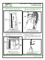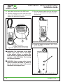
1
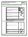
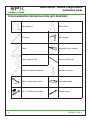
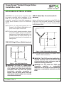
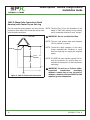
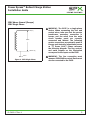
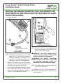
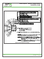
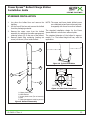
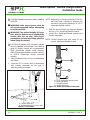
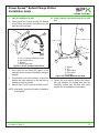
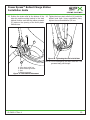
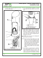
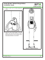
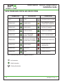
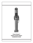
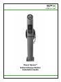
Power Xpress™
Bollard Charge Station
Installation Guide
Power Xpress™ Bollard Charge Station
Installation Guide
Technical Support
1-877-805-EVSE (3873)
Copyright © 2012 Service Solutions U.S. LLC
All rights reserved.
The information, specifications, and illustrations in this guide are based on the latest
information available at the time of printing. Service Solutions U.S. LLC reserves the right to
make changes at any time, without notice.
2
EL-50600-17 Rev. A
Power Xpress™ Bollard Charge Station
Installation Guide
TABLE OF CONTENTS
INSTALLATION SAFETY...................................................................................................4
INSTALLATION CONTENTS: BOLLARD AND EVSE (EL-50650)............................................5
Power Xpress EVSE (EL-50600-300) for Bollard Charge Station.....................................5
Bollard and Hardware (EL-50600-500)........................................................................5
TOOLS SUGGESTED FOR INSTALLATION (NOT PROVIDED)...............................................6
APPLICABLE ELECTRICAL SYSTEMS.................................................................................7
220/240V Single Phase (North America)......................................................................7
208V 3-Phase Wye Connection (North America)...........................................................7
240V 3-Phase Delta Connection (North America) with Center Tap on One Leg...............8
230V Above Ground (Europe)
230V Single Phase.....................................................................................................9
ELECTRICAL REQUIREMENTS FOR BATTERY CHARGING.................................................10
AMPERAGE AND BREAKER PARAMETERS.......................................................................11
STANDARD INSTALLATION...........................................................................................13
EVSE POWER AND STATUS LED INDICATIONS...............................................................22
TROUBLESHOOTING....................................................................................................23
Ground Fault Circuit Interrupt (GFCI) Tripped............................................................24
Missing Ground.......................................................................................................24
LIMITED WARRANTY....................................................................................................25
EL-50600-17 Rev. A
3
Power Xpress™ Bollard Charge Station
Installation Guide
INSTALLATION SAFETY
SAVE THESE IMPORTANT SAFETY INSTRUCTIONS.
This guide contains important instructions that must be followed during the installation of the electric vehicle supply equipment (EVSE). All instructions should be carefully read before installation of the EVSE.
WARNING: Turn OFF the circuit breaker
at the service or distribution panel before
performing any electrical work or repairs.
WARNING: Use this EVSE within the
specified operating parameters. Failure to
do so may result in injury or death.
WARNING: The EVSE should be installed by
a licensed electrician in accordance with all
local electrical codes, ordinances, and all
authorities having jurisdiction.
WARNING: Locate and install this EVSE in
a location where the charge cable will not
be stepped on, tripped over, or subject to
damage or stress.
WARNING: Do not install the EVSE near
flammable, explosive, or combustible
materials. Do not locate or store flammable,
explosive, or combustible materials near the
EVSE.
WARNING: The EVSE must be connected to a
grounded, metal, permanent wiring system,
or an equipment-grounding conductor
must be run with the circuit conductors
and connected to the equipment grounding
terminal on the EVSE.
WARNING: Improper installation of the
EVSE can result in personal injury or
product damage.
WARNING: This EVSE installation guide
is not a substitute for electrical safety
precautions.
4
CAUTION: Incorrect installation of the EVSE
can result in damage to the vehicle’s battery
and to the EVSE itself. These damages will void
the warranty for the vehicle and the EVSE.
CAUTION: Do not operate the EVSE in
temperatures beyond its operating range of
-40°F to +122°F (-40°C to +50°C).
EL-50600-17 Rev. A
Power Xpress™ Bollard Charge Station
Installation Guide
INSTALLATION CONTENTS: BOLLARD AND EVSE (EL-50650)
Power Xpress EVSE (EL-50600-300) for Bollard Charge Station
POWER
STATUS
EVSE (including attached cable with strain
1 relief and grommet, input/output decals, flag
tag, and vehicle coupler)
RESET
1-877-805-EVSE (3873)
http://evse.spx.com
1 Decal and cover kit
1 Cable-management hook
1 Power Xpress Bollard Charge Station Installation Guide
1 Power Xpress EVSE User Manual
Bollard and Hardware (EL-50600-500)
1
Bollard (including upper and lower plastic
covers)
2
Cable-management retaining screws (preinstalled)
1
Locating set screw (plastic bag attached to bollard)
EL-50600-17 Rev. A
5
Power Xpress™ Bollard Charge Station
Installation Guide
TOOLS SUGGESTED FOR INSTALLATION (NOT PROVIDED)
Tape measure
Wire cutters
2-ft Level
Wire stripper
Pencil
Nonmetallic wire stripper
Power hammer drill
Masonry drill bit set
Small flat-blade screwdriver
Needle-nose pliers
7/16-in. Open-end wrench
Expandable pliers
1/2-in. Ratchet and sockets
Torque wrench
7/16in
6
EL-50600-17 Rev. A
Power Xpress™ Bollard Charge Station
Installation Guide
APPLICABLE ELECTRICAL SYSTEMS
IMPORTANT: The on-site service connection must
be properly identified before installation of the
EVSE. If you are unsure of the available service
connection, consult the local utility company or
contact Service Solutions US at 1-877-805-EVSE
(3873).
NOTE: The L1, L2, and ground outputs (H, N for
Europe) in the following illustrations correspond to the inputs on the EVSE.
208V 3-Phase Wye Connection (North
America)
Any two of the legs can be used to provide 208V to the
EVSE with a Wye-connected secondary. For example,
L1 and L2, or L1 and L3, or L2 and L3. Reference the
wiring diagram below.
L3 (NOT USED)
NOTE: For the (earth) ground connection, always
connect the neutral at the service panel to
earth ground. Ground fault protection is not
possible unless the neutral (center tap on
the service transformer) is connected to an
earth ground.
L1
120V
NEUTRAL
(NOT USED)
220/240V Single Phase (North America)
120V
L2
L1
GND
120V
Figure 2. 208V 3-Phase Wye Connection
240V
NEUTRAL
(NOT USED)
NOTE: A current-carrying neutral is not required for the
EVSE for 208V connections.
120V
L2
Figure 1. 220/240V Single Phase
WARNING: The EVSE is a single-phase
device. Do not connect all three phases
of a 3-phase feed. Only three wires are
connected, take care that the service
transformer secondary connection is
known, and the three wires from the
main-panel circuit breaker are correctly
connected and labeled.
EL-50600-17 Rev. A
WARNING: The EVSE must be installed by a
licensed electrician and in accordance with
all local electrical codes, ordinances, and all
authorities having jurisdiction.
WARNING: Do not install the EVSE near
flammable, explosive,
or
combustible
materials. Do not locate or store flammable,
explosive, or combustible materials near the
EVSE.
7
Power Xpress™ Bollard Charge Station
Installation Guide
240V 3-Phase Delta Connection (North
America) with Center Tap on One Leg
One leg must be center-tapped, and only the two
phases on either side of the center tap can be used
with the delta connection.
NOTE: The third line (L3 on the illustration of the
delta) is 208V, with respect to the neutral,
and is sometimes referred to as a “stinger.”
WARNING: Do not use this third line.
L3 (NOT USED)
NOTE: The two used phases must each measure
120V to neutral or ground.
L2
CENTER TAP
L1
L1
NOTE: Consult the utility company or the transformer manufacturer’s literature to verify
that the single leg can supply the required
power.
120V
NEUTRAL
(NOT USED)
240V
NOTE: The EVSE will only operate properly if it detects the presence of a ground wire connected to a neutral point on the transformer
secondary.
120V
L2
GND
Figure 3. 240V 3-Phase Delta Connection
8
WARNING: Do not use a 3-phase deltaconnected
transformer
secondary
without a center tap on one leg and/or
without a neutral point available for the
required ground connection.
EL-50600-17 Rev. A
Power Xpress™ Bollard Charge Station
Installation Guide
230V Above Ground (Europe)
230V Single Phase
LINE (H)
230VAC
NEUTRAL (N)
EARTH
Figure 4. 230V Single Phase
EL-50600-17 Rev. A
WARNING: The EVSE is a single-phase
device. When connecting the line and
neutral wires, take care that the service
transformer secondary connection is
known, and the wires from the main
circuit breaker panel are correctly
connected and labeled. The following
service connections are primarily used in
Europe and Australia (sometimes known
as “TT Power Grid”). Please reference
the following diagram. The line, neutral,
and earth outputs on the illustration
correspond to the inputs on the EVSE.
WARNING: The line connection must
measure 230V RMS to neutral. Earth must
also be connected to the EVSE.
9
Power Xpress™ Bollard Charge Station
Installation Guide
ELECTRICAL REQUIREMENTS FOR BATTERY CHARGING
CAUTION: The AC electrical connection must
have a grounded, dedicated service-main. No
other loads shall be connected to the same
circuit. Use of a non-dedicated circuit could
exceed the current rating of the circuit breaker
and cause it to trip or open.
G
H
A
F
6 in.
B
C
D
18 in.
24 in.
E
A. Conduit extending up to 24 in. (61 cm) from
ground level or per local code
B. Conduit sweep
C. THWN rigid-metal, Schedule 40 or 80 conduit
D. THWN nonmetallic, Schedule 40 or 80 conduit
E. UF burial wire (ground solid)
F. Ground level
G. Service panel
H. Minimum wire length of 66 in. (168 cm)
Figure 5. Wire Run Variations
10
WARNING: The EVSE must be installed
by a licensed electrician in accordance
with all national and local electrical codes,
ordinances, requirements and all authorities
having jurisdiction.
The conduit may extend up to 24 in. (61 cm) from
ground level. The wiring should extend 66 in. from
the base mounting of the bollard. A sweep is used to
direct the circuit from the conduit to the electric circuit
from the service panel. The three types of acceptable
wire runs are:
• THWN rigid metal Schedule 40 or 80 conduit,
buried 6 in. (15 cm) below ground level, or per
local electrical code.
• THWN nonmetallic Schedule 40 or 80 conduit,
buried 18 in. (46 cm) below ground level, or
per local electrical code.
• UF burial wire (ground solid), buried 24 in. (61
cm) below ground level, or per local electrical
code.
• THHN, THWN, or THWN-2 wires are recommended to allow for proper space requirements
inside the 1/2 in. flexible conduit required inside the bollard.
EL-50600-17 Rev. A
Power Xpress™ Bollard Charge Station
Installation Guide
AMPERAGE AND BREAKER PARAMETERS: FIELD REQUIREMENTS AND
ADJUSTMENTS FOR EVSE INSTALLATION (NOT REQUIRED FOR 40 AMP
CIRCUIT INSTALLATION)
1. Unpack the EVSE.
A
D
C
B
A. EVSE body
B. EVSE cable
C. Strain relief with grommet
D. 18 in. (46 cm)
Figure 6. EVSE
NOTE: The EVSE has been factory set at 30 amp
output for a 40 amp circuit. Proceed to
“Standard Installation” if installing on a 40
amp circuit. For all other amperages, complete Steps 2 and 3 for EVSE adjustment.
2. Remove the domed cap from the currentadjustment selector (positioned just above the
reset button on the front of the EVSE).
3. Using a small, flat-blade screwdriver, set the
current-adjustment selector to the applicable
output current-limiting setting as specified in
“Figure 8. Current-Adjustment Settings”.
EL-50600-17 Rev. A
Figure 7. Setting the
Current-Adjustment Selector
NOTE: Positions 6, 7, 8, 9, 0 are not used (X) and
are non-operational. The EVSE will not
function under these settings.
WARNING: The EVSE setting cannot
exceed ampacity ratings of field service
wires or branch circuit protectors.
WARNING: See “output” specification
label located on the side of the EVSE
for maximum amperage setting, per
limitations of vehicle cable and coupler.
NOTE: The EVSE must be de-rated to match line
service power limitations.
CAUTION: Use 75°C (600V) approved wire,
conductor temperature at 30°C ambient in wet
or dry locations.
11
Power Xpress™ Bollard Charge Station
Installation Guide
Figure 8. Current-Adjustment Settings
12
EL-50600-17 Rev. A
Power Xpress™ Bollard Charge Station
Installation Guide
STANDARD INSTALLATION
1. Lay down the bollard box and remove the
banding.
2. Lift the top off the box and remove the bollard
from the packaging material.
3. Remove the upper cover from the bollard
assembly by removing the cable-management
retaining screws (E) on the rear of the bollard.
4. Remove plastic bag containing locating set
screw (not shown) from inside bollard.
NOTE: The upper and lower plastic bollard covers
are a matched set and cannot be used interchangeably with those from other bollards.
The standard installation design for the Power
Xpress Bollard is a bolt-down external plate.
The standard diameter of the bollard is approximately 7 in. The bollard height will vary with the
application.
A
Figure 10. Typical Installation
B
10 in.
7½ in.
E
10 in.
D
7½ in.
C
15/16 in.
Figure 11. Base Plate Dimensions
A. Upper plastic cover
B. Metal Bollard
C. Lower plastic cover (Do not remove)
D. Seal
E. Cable-management retaining screws
Figure 9. Bollard Disassembly
EL-50600-17 Rev. A
13
Power Xpress™ Bollard Charge Station
Installation Guide
CAUTION: Read all instructions before installing
the EVSE.
WARNING: Main service power must be
off and disconnected before attempting
to install the EVSE.
WARNING: The bollard weighs 20 lb per
foot, and the bottom end is significantly
heavier than the top end. Take proper
precautions and use safe lifting practices
when lifting the bollard.
CAUTION: All adapter and connection fittings
must be classified as liquid-tight. The following
types of flexible conduit are recommended:
LFMC (liquid-tight flexible metal conduit),
LFNC-B (liquid-tight flexible nonmetal conduit),
or LFNC-A (liquid-tight fexible nonmetal
conduit).
NOTE: Depending on the type and size of the conduit stand pipe, a variety of adapters may
be used to convert the stand pipe to 1/2-in.
liquid-tight flexible conduit.
3. Slide the wires through the required adapters
and the 1/2-in. liquid-tight flexible conduit.
4. Install 1/2-in. liquid-tight flexible conduit to the
conduit stand pipe.
NOTE: Consult national and local codes for approved, liquid-tight flexible conduit.
A
1. Place the bollard where it is to be installed and
drill holes.
B
2. Install the 3/4 in. anchor bolts in accordance
with industry standards for the type of
mounting being performed.
C
A
D
A. 1/2-in. liquid-tight flexible conduit
B. Liquid-tight fitting
C. Threaded adapter
D. Conduit stand pipe
Figure 13. Stand Pipe Conduit Connection
B
A. Conduit stand pipe
B. Marked locations for anchor bolts
Figure 12. Drill Holes
14
EL-50600-17 Rev. A
Power Xpress™ Bollard Charge Station
Installation Guide
5. Place the bollard on its side.
6. Gently guide the conduit through the bottom
of the bollard and position the bollard over the
bolts and onto the base.
10. Install a washer, lock washer, and nut on each
bolt.
A
A
B
D
C
A. 1/2-in. liquid-tight flexible conduit
B. Liquid-tight fitting
C. Adapter
D. Bollard base plate
Figure 14. Guide Conduit into Bollard
7. Use a level on two sides (90° apart) of the
bollard to check whether the bollard is standing
straight.
8. If the bollard is not plum and level, remove the
bollard and place washers on the lag bolts as
needed to level the bollard.
9. Repeat Steps 7 and 8 until the bollard is level.
E
B
D
C
A. Bollard
B. Nut
C. Lock washer
D. Flat washer
E. Lag Bolt
Figure 15. Install Washers and Nuts
11. Tighten the nuts evenly around the bollard.
Any gap between the bollard base and the
mounting surface may be filled with caulk
suitable for the installation environment.
NOTE: Alternately, double-nut leveling installation
is acceptable.
EL-50600-17 Rev. A
15
Power Xpress™ Bollard Charge Station
Installation Guide
12. Position the conduit on the left side of the
bollard (opposite the open metal slot side).
14. Mark 1/2-in. liquid-tight flexible conduit for
length based on the required radius bend to
attach to the top of the EVSE.
B
A
B
C
A
A. Location to cut conduit
B. Precut hole in top of EVSE
C. 1/2-in. liquid-tight flexible conduit
Figure 19. Location to Cut Conduit
A. Tapered EVSE guide bracket
B. 1/2-in. liquid-tight flexible conduit
Figure 17. Conduit Positioned on Left
13. Gently guide the EVSE body down through the
bollard until it rests on the top of the tapered
guide bracket.
15. Cut 1/2-in. liquid-tight flexible conduit to
length. Do not cut wires.
16. Install approved, liquid-tight fittings to attach
1/2-in. liquid-tight flexible conduit to top of
EVSE.
A
A
C
B
B
A. EVSE
B. Tapered EVSE guide bracket
C. 1/2-in. liquid-tight flexible conduit
Figure 18. EVSE Resting on Bracket
16
A. 1/2-in. liquid-tight flexible conduit
B. Liquid-tight fitting
Figure 20. Fittings Installed
EL-50600-17 Rev. A
Power Xpress™ Bollard Charge Station
Installation Guide
NOTE: All connections must be liquid-tight.
17. Feed wires into the hole in the top of the EVSE
and attach 1/2-in. liquid-tight flexible conduit
with a liquid-tight fitting.
19. Strip wires and wire them into the EVSE. Refer
to label on inside of EVSE cover or details on
circuit board. Torque terminal screws to 10.62
± 1 in-lb (1.2 ± 0.12 Nm).
A
B
C
Figure 22. Wires Installed into EVSE
A. 1/2-in. liquid-tight flexible conduit
B. Liquid-tight fitting
C. EVSE
Figure 21. Wires Inserted into EVSE and
Conduit Installed
20. Install EVSE cover.
A
18. Cut wires to length.
B
A. 1/2-in. liquid-tight flexible conduit
B. EVSE cover
Figure 23. EVSE Cover Installed
EL-50600-17 Rev. A
17
Power Xpress™ Bollard Charge Station
Installation Guide
21. Apply decal to the front of the EVSE cover.
22. Continue lowering the EVSE until the front
edge of the EVSE bottom cover rests on the
ledge in the bollard front opening.
23. Push any excess conduit down into the bollard.
A loop will extend above the bollard and fit in
the top cover.
A
B
A. EVSE bottom cover
B. Ledge in bollard front opening
Figure 24. EVSE Lowered into Position
Figure 25. Excess Conduit Pushed into Bollard
24. Install the locating set screw to 50 ± 5 in-lb
(5.5 ± 0.55 Nm).
WARNING: The lower edge of the EVSE
bottom cover must rest on the ledge
of the bollard. Failure to position the
EVSE correctly in the opening will cause
damage to the EVSE when the locating
set screw is tightened.
WARNING: Never use any other size set
screw to secure the EVSE in place. If
the set screw is too long, it will prevent
installation of the upper cover.
Figure 26. Tightening the Locating Set Screw
18
EL-50600-17 Rev. A
Power Xpress™ Bollard Charge Station
Installation Guide
25. Position the strain relief at the bottom of the
side slot metal mounting bracket in the steel
bollard. Position such that the rubber grommet
(D) seats on the opening of the lower plastic
bollard cover.
26. Tighten the inner strain-relief nut (A) inside the
bollard hand tight. Using expandable pliers,
tighten the nut an additional 1/4 turn.
A
B
D
Figure 28. Tightening the Strain-Relief Nut
C
NOTE: Do not overtighten the strain-relief nut. The
grommet may pull through.
A. Inner strain-relief nut
B. Metal mounting bracket
C. Seal
D. Rubber grommet
Figure 27. Strain Relief Placement
EL-50600-17 Rev. A
19
Power Xpress™ Bollard Charge Station
Installation Guide
27. Carefully lower the upper plastic cover down
onto the bollard base.
28. Use a small flat-blade screwdriver or similar
tool to guide the upper plastic cover into the
seal.
5.AFT
ER SAFE
TY TEST
VEHIC
LE IS
VERIF
CHAR
ICATION
GING
- STATU
T COMP
.
S LIGHT
LETIO
STATUS.
N OF
BEGINS
CHAR
TO FLAS
7.UNP
G - STAT
LUG VEHIC
H GREE
US LIGHT
N, INDIC
INDIC
LE COUP
RETU
ATOR
ATING
RNS TO
LER
CHAN
8.RET
SOLID
GES BACK (CONNECT
URN CABL
GREE
TO AMBE OR) FROM
N ILLUM
NOTE
E AND
: EVSE
VEHIC
INATI
COUP
ON
WILL
LE INLET
LER BACK R ILLUMINATI
RESU
ON STAT
(RECEPTA
ME CHAR
TO STOW
WARNI
E.
ABLE
CLE)
GING
- STAT
UPON
POSIT
NG: RED
US
ION AT
REST
ORAT
STATUS
ION OF EVSE.
LIGHT
FAULT
AVERTI
INTER
RUPT
SSEMENINDICATION ILLUMINATED
ED GRID
- SEE
POWE
T: LA LUMIAND OPERATING
OPER
R.
ATING
INSTR
WARNIN
MANU
OPER ERE DE STAT
AL FOR
G: IF UNIT INSTRANT POUR L’INDUT ROUG UCTIONS.
UCTIONS
E ECLA
ICATI
FAILS
IREE
AVERTI THIS DEVIC
ON DE
OPER
TO OPER
- VOIT
FAUT
ATE PER ANTES.
LE MANU
SSEMEN E, CONT
E ET
LES
THE OPER
EL
T:Sl appa ACT QUALIFIED
TECH ATING INSTR
EMPL reil ne fonct
NICIA
OI
N FOR UCTIONS
ionne
FOR
TECH Ne pas utilis
DO
SERV
pas selon
NICIE
USE
ICE OR NOT USE
N QUAL er ce perip
les
WIT
REPA
IFIE pour herlq instruction
IR.
VENTILH ELECTR
s
entre ue, conta
IC VEH tien ou reparctez
ATION
ation
ICLES
NOT
.
REQ
6.POS
A
UIRED ONLY
A
B
D
C
A. Upper plastic cover
B. Seal
C. Lower plastic cover
D. Small flat-blade screwdriver
Figure 30. Seal Installation
29. While gently pressing down on the upper
plastic cover, carefully slide the screwdriver
around the bollard to extend the upper lip
of the seal over the upper plastic cover. The
upper cover may need to be tapped gently to
fully seat it in the seal.
CAUTION: Use care not to cut or damage the
seal during this procedure.
B
A. Upper plastic cover
B. Metal bollard
Figure 29. Upper Bollard Lowered into Place
20
NOTE: When the upper plastic bollard cover is fully
seated, the rear cable-management holes
will be in line with the threaded holes in
the steel portion of the bollard base and the
rubber cable grommet will be centrally located with respect to the rubber seal.
Verify the cable-management holes and the
rubber cable grommet are each properly
aligned.
30. Use a 5/16-in. hex-head wrench to install the
rear cable-management hook with the two
cable-management retaining screws. The
torque on the cable-management retaining
screws should be 60 ± 5 in-lb (6.8 ± 0.55 Nm).
EL-50600-17 Rev. A
Power Xpress™ Bollard Charge Station
Installation Guide
31. Loop the cable onto the cable-management
holder.
Figure 31. Cable Looped on Hook
32. Switch the main circuit breaker to the ON
position and verify that the Power LED is
illuminated solid green and the Status LED is
illuminated solid amber on the EVSE.
Figure 32. Complete Installation
EL-50600-17 Rev. A
21
Power Xpress™ Bollard Charge Station
Installation Guide
EVSE POWER AND STATUS LED INDICATIONS
POWER LED
STATUS LED
CONDITION
(OFF)
(OFF)
NO SERVICE SUPPLY POWER
GREEN SOLID
AMBER SOLID
EVSE POWERED; VEHICLE
COUPLER NOT CONNECTED
GREEN SOLID
GREEN SOLID
WAITING TO CHARGE
GREEN SOLID
GREEN BLINKING
VEHICLE IS CHARGING
GREEN SOLID
1 OR 2 RED BLINKS
EVERY 2 SECONDS
PILOT CHARGING ERROR*
GREEN SOLID
SOLID RED THEN GREEN
BLINK EVERY 2 SECONDS
GROUND FAULT DETECTED*
GREEN SOLID
RED BLINKING
GROUND MONITOR
INTERRUPTED*
GREEN SOLID
RED SOLID
OPERATION FAULT*
GREEN SOLID
(OFF)
OPERATION FAULT*
*See Troubleshooting section for suggested solutions.
22
- No illumination
- Solid illumination
- Flashing illumination
EL-50600-17 Rev. A
Power Xpress™ Bollard Charge Station
Installation Guide
TROUBLESHOOTING
If there is a charging issue proceed with the following steps. If the issue persists after three attempts
call Service Solutions U.S. LLC at 1-877-805-EVSE (3873) for assistance.
Problem Indicated by LED Status
Solution
Pilot charging error
1. Verify supply-side power. The green POWER LED should be on.
If green POWER LED is off, locate load center/panel and reset
breaker.
2. Press the master clear RESET button on the front panel of the
EVSE to attempt a charge-restart.
3. If the red STATUS LED remains on, disconnect the EVSE coupler
from the vehicle charge port, wait 10 seconds, and reconnect
the coupler.
Ground fault detected
1. Disconnect main service power at service panel.
2. Disconnect the EVSE coupler from the vehicle.
3. Inspect the EVSE connector and the vehicle charge port verifying
both are clean and undamaged. If vehicle charge port needs
cleaning, follow manufacturer instructions for cleaning. Clean
EVSE connector with a dry or damp cloth if necessary.
4. Restore main service power.
5. Reconnect the coupler to the vehicle port.
Ground monitor interrupted
1. Disconnect main service power at service panel.
2. Disconnect the EVSE coupler from the vehicle.
3. Inspect the EVSE connector and the vehicle charge port verifying
both are clean and undamaged. If vehicle charge port needs
cleaning, follow manufacturer instructions for cleaning. Clean
EVSE connector with a dry or damp cloth if necessary.
4. Restore main service power.
5. Reconnect the coupler to the vehicle port.
Operation fault
1. Verify supply-side power. The green POWER LED should be on.
If green POWER LED is off, locate load center/panel and reset
breaker.
2. Press the master clear RESET button on the front panel of the
EVSE to attempt a charge-restart.
3. If the red STATUS LED remains on, disconnect the EVSE coupler
from the vehicle charge port, wait 10 seconds, and reconnect
the coupler.
EL-50600-17 Rev. A
23
Power Xpress™ Bollard Charge Station
Installation Guide
Ground Fault Circuit Interrupt (GFCI) Tripped
If the EVSE detects a ground fault, power will be interrupted and the STATUS LED will illuminate (red
flash with intermittent green). The EVSE will attempt to reset automatically and re-attempt charging (see note below on European models). If the fault condition persists after an initial automatic
attempt, per the code, the EVSE waits 15 minutes before a second attempt is made. A total of four
attempts will be made to restore vehicle charging. If the charging mode cannot be restored, the STATUS LED will illuminate solid red, and the EVSE will stay in fault mode.
NOTE: Automatic reset feature after ground fault (STATUS LED will be solid red) does not apply to
European EVSE models. European standards dictate that user intervention is required by
pressing the master clear RESET button on the front of the EVSE housing. If ground fault
condition clears, EVSE will resume charging.
Missing Ground
If the EVSE detects a missing ground connection (rapid red flashing LED), power will be interrupted
and the EVSE will not be capable of charging vehicle until a ground connection has been detected.
Disconnect service power (breaker) and disconnect vehicle coupler from vehicle and contact a qualified Service Solutions U.S. LLC technician to validate the presence of a proper ground.
24
EL-50600-17 Rev. A
Power Xpress™ Bollard Charge Station
Installation Guide
LIMITED WARRANTY
THIS WARRANTY IS EXPRESSLY LIMITED TO THE ORIGINAL PURCHASER OF SERVICE SOLUTIONS U.S. LLC EVSE
PRODUCT.
•
Power Xpress Bollard is warranted against defects in materials and workmanship for one year from the date
of installation.
•
EVSE Cables and Connectors are warranted against defects in materials and workmanship for 90 days from
the date of delivery.
This warranty is only valid to the original purchaser of the EVSE and is not transferable. All warranty claims must be
made within the warranty period and proof of purchase must be supplied. This warranty does not cover the cost of
freight to return the EVSE to Service Solutions U.S. LLC.
The sole and exclusive remedy for any EVSE found to be defective is repair or replacement, at the option of Service
Solutions U.S. LLC. The existence of a defect shall be determined by Service Solutions U.S. LLC in accordance with
procedures established by Service Solutions U.S. LLC. No one is authorized to make any statement or representation
altering the terms of this warranty. This warranty covers only those defects that arise as a result of normal use of
the EVSE and does not cover any other problems including those that arise as a result of abuse, neglect, improper
maintenance, care or modification, operation outside of the EVSE’s specifications or in a manner inconsistent with
instructions regarding use. Service Solutions U.S. LLC does not make any representation or warranty regarding the
continuous availability of electrical service to the EVSE.
This warranty gives the original purchaser specific legal rights. The original purchaser may also have other rights
which vary from state to state. To the extent that this warranty is inconsistent with applicable law, this warranty will
be deemed modified to be consistent with such local law.
DISCLAIMER
TO THE EXTENT PERMITTED BY APPLICABLE LAW AND EXCEPT AS EXPRESSLY PROVIDED IN THE LIMITED
WARRANTY, SERVICE SOLUTIONS U.S. LLC MAKES NO WARRANTY WITH RESPECT TO THE EQUIPMENT OR THE
SERVICES, WHETHER EXPRESS, IMPLIED, STATUTORY OR OTHERWISE. SERVICE SOLUTIONS U.S. LLC EXPRESSLY
DISCLAIMS ALL OTHER WARRANTIES, INCLUDING, BUT NOT LIMITED TO, THE IMPLIED WARRANTIES OF NONINFRINGEMENT OF THIRD PARTY RIGHTS, MERCHANTABILITY AND FITNESS FOR A PARTICULAR PURPOSE.
SERVICE SOLUTIONS U.S. LLC DOES NOT WARRANT UNINTERRUPTED OR ERROR FREE OPERATION OF THE
EQUIPMENT.
The EVSE should be installed only by a licensed electrician and in accordance with all local and national codes
and standards.
All information, illustrations, and specifications contained in this installation guide are based on the latest information
available at the time of publication. The right is reserved to make changes at any time without obligation to notify
any person or organization of such revisions or changes. Further, this Guide is provided “as is” and Service Solutions
U.S. LLC shall not be liable for errors contained herein.
LEGAL LIMITATION OF LIABILITY
TO THE EXTENT ALLOWED BY APPLICABLE LAW, IN NO EVENT SHALL SERVICE SOLUTIONS U.S. LLC OR ITS
SUPPLIERS BE LIABLE FOR DIRECT, INDIRECT, SPECIAL, INCIDENTAL OR CONSEQUENTIAL DAMAGES, WHETHER
BASED ON CONTRACT, TORT, OR ANY OTHER LEGAL THEORY AND WHETHER ADVISED OF THE POSSIBILITY OF
SUCH DAMAGES.
Some states do not allow the exclusion or limitation of incidental damages for some products, so the limitations or
exclusions contained herein may not apply.
COPYRIGHTS, TRADEMARKS
No part of this guide may be reproduced, stored in a retrieval system, or transmitted, in any form or by any means,
electronic, mechanical, photocopying, recording, or otherwise, without the prior written permission of Service
Solutions U.S. LLC. Service Solutions U.S. LLC is a registered trademark of Service Solutions U.S. LLC. All third party
trademarks are the property of their respective owners.
EL-50600-17 Rev. A
25
EL-50600-17 Rev. A
© Service Solutions U.S. LLC