1
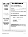
OWNER'S
MANUAL
MODEL
NO.
580.326720
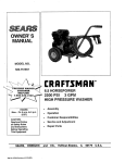
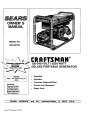
CRAFTSMAN+
120-240 VOLT / 3250 WATT
DELUXE PORTABLE GENERATOR
I
Mon.- Fri. 8 a.m. to 5 p.m
HOURS:
J
(CST)
CAUTION:
Read and Follow
all Safety Rules
and Instructions
Before Operating
This Equipment
•
Assembly
•
Operation
•
Customer
•
Service
•
Repair Parts
Responsibilities
and Adjustment
II
SEARS,
ROEBUCK
' PartNo. 97228 Revision 3 (2/13/97)
and
CO.,
HoffmanEstates,
IL
6017_)
•
U.S.A.
I
'
SAFETY RULES
,_
TACT
SPARK
PLUG,DISCONNECT
TO PREVENT SPARK
ACCIDENTAL
STARTING
WHEN WIRE
SE'i-rlNG
UP, IT
TRANSPORTING,
CAUTION:
ALWAYS
PLUG WIRE
AND PLACE
WHERE
CANNOT CONADJUSTING OR MAKING REPAIRS TO YOUR GENERATOR.
IMPORTANT
THIS GENERATOR IS DESIGNED FOR OUTDOOR USE ONLY. USING THIS GENERATOR INSIDE ANY BUILDING OR
ENCLOSURE, INCLUDING THE GENERATOR COMPARTMENT OF A RECREATIONAL VEHICLE (RV), IS DANGEROUS.
FIRE OR AN EXPLOSION MAY RESULT. NO USER PERFORMED MODIFICATIONS, INCLUDING VENTING OF EXHAUST
AND/OR COOUNG VENTILATION, WILL ELIMINATE THE DANGER.
•
•
•
•
•
•
=
•
If this unit is used for backup power in the event of
a utilitypower failure, take the followingsteps: BEFORECONNECTING
THE GENERATOR TO AN
ELECTRICAL SYSTEM OPEN THE MAIN CIRCUIT BREAKER OR MAIN SWITCH SERVING
THE SYSTEM TO ISOLATE THE GENERATOR
SYSTEM FROM THE ELECTRIC UTILITY. FAILURE TO ISOLATE THE GENERATOR AND UTILITY SYSTEMS MAY RESULT IN DAMAGE TO
THE GENERATOR AND MAY ALSO RESULT IN
INJURY OR DEATH TO ELECTRIC UTILITY
WORKERS DUE TO BACKFEED OF ELECTRICAL ENERGY.
This generator supplies dangerously high electrical
voltages. Use care to prevent extremely hazardous
and possibly lethal electrical shock. Never permit
any unqualified person(s) to operate or service the
unit.
DO NOT operate this equipment in the rain, while
standing in water, while barefoot, or while hands or
feet are wet. Dangerous electrical shock will result.
The spark arrestor muffler can become extremely
hot. DO NOT operate this equipment in areas where
combustible material such as grass, leaves or paper
products can come in contact with the muffler.
Maintain all wiring, extension cords, etc., in good
condition. Worn, bare, frayed, or otherwise damaged wiring and cord sets may cause dangerous
electrical shock and may also result in damage to
equipment and/or property.
The National Electrical Code requires that the generator be properly connected to an approved earth
ground. ;Local electrical codes may also require
proper grounding of the unit. See ASSEMBLY sectionJ.or rnO"regroundirlg information.
Wire gauge-size_ of wiring and cord sets must be
' large enough_o h_ndle the maximum electrical load
;; to whtch ithey_ wil|beisubjected.
Most devices require_cord sets I'atel_l 125 AC volts at 20 to 30
• amperes'or 250 AC yolts at 20 amps (or greater).
Some devices may require a higher or lower rating.
Refer to the Owner's manual of the electrical device
for the man.ufacture)fs recommendations.
Cord
sets that;are_tooismall in diameter or too long will
overheat; _m_
d_maged and may cause property damage !an_or _lectdcal shock.
The Oenerator e_gin_ consumes oxygen and gives
off DEADLY ica_on _onoxide gas through its exhaust system. This dangerous gas, if breathed in
sufficient concentrations, can cause unconsciousrfess _or eve_ ddathJ Operate this equipment out-
doors only, in well ventilated areas where exhaust
gases cannot accumulate and endanger people or
animals.
•
•
•
•
•
•
•
•
•
Gasoline is extremely FLAMMABLE and its vapors
are EXPLOSIVE. Comply with all laws regulating
the storage and handling of gasoline. DO NOT
permit smoking, open flames, sparks or heat in the
vicinity while handling gasoline. Avoid spilling
gasoline on a hot engine. DO NOT fill fuel tank
while engine is running or hot. Clean off any spilled
gasoline before starting engine.
DO NOT fill fuel tank completely full. Allow room at
top of tank for fuel expansion or fuel may expand
and overflow onto a hot engine.
Drain all gasoline from tank before transporting your
generator inside your car or other vehicle.
DO NOT store the generator with fuel in tank where
gasoline vapors might reach an open flame, spark,
or pilot light, as on a furnace, water heater, dryer,
etc. FIRE or an EXPLOSION might result.
DO NOT insert any object or tool through cooling air
slots or openings of the engine or generator, even
if the engine is not running. Damage to the unit or
personal injury may result.
DO NOT attempt to change the engine governed
speed.. Factory settings are correct when you receive the unit. Excessively high engine speeds may
result in injury or damage to equipment.
DO NOT use the unit if ithas been damaged. Repair
or replace all damaged or defective components
before you run the unit.
DO NOT permit children to operate or service the
generator.
Read your Owner's Manual carefully. Only persons
who are familiar with these safety.I;ules and have
been properly instructed in the use of this product
should be permitted to use the product.
LOOK FOR THIS SYMBOL TO POINT OUT IMPORTANT
SAFETY PRECAUTIONS.
MEANS
"ATTENTION!!!
BECOME ALERT!!!
YOUR SAFETY IS INVOLVED."
IT
CONGRATULATIONS
onyourpurchase
ofaSearsCrafts- PRODUCT SPECIFICATIONS
manGenerator.It has beendesigned,engineered
and
manufactured
to giveyou the best possible dependability Generator Specifications
and performance.
Should you experience any problem you cannot easily
remedy, please contact your nearest Sears Service Center/Department or call the 1-800 number listed on the front
of this manual. We have competent, well-trained technicians and the proper tools to service or repair this unit.
Please read and retain this manual. The instructions will
enable you to assemble and maintain your generator properly. Always observe the 'SAFETY RULES."
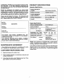
MODEL
NUMBER
580.326720
SERIAL
NUMBER
RATED MAXIMUM
POWER
3250 Watts (3.25 kW)
RATED VOLTAGE
120/240 Volts a-c
RATED MAXIMUM
LOAD CURRENT
27.1/13.5 a-c amperes
RATED FREQUENCY
60 Hz at 3600 rpm
PHASE
Single Phase
Engine Specifications
RATED HORSEPOWER
6.5 at 3600 rpm
DISPLACEMENT
191cc
SPARK PLUG: Type:
Champion RC12YC or
or equivalent
0.030 inch (0.76mm)
DATE OF
Set Gap to:
PURCHASE
MAXIMUM
FULL TANK
OPERATING TIME (hrs)
THE MODEL AND SERIAL NUMBERS WILL BE
FOUND ON A DECAL ATTACHED TO THE GENERATOR STATOR CAN.
YOU SHOULD RECORD BOTH SERIAL NUMBER
AND DATE OF PURCHASE AND KEEP IN A SAFE
PLACE FOR FUTURE REFERENCE.
MAINTENANCE
AGREEMENT
A Sears Maintenance Agreement is available on this product. Contact your nearest Sears store for details.
CUSTOMER
RESPONSIBILITIES
•
Read and observe the safety rules.
•
Follow regular schedule in maintaining, caring for and
using your generator.
•
Followthe instructions under"Maintenance" and "Storage" sections of this Owner's Manual.
full load
5.5
1/2
7.5
3/4
10.5
1/4
14
GASOLINE CAPACITY
4 U.S. cjallons
OIL (620ml)
SAE 30 Oil
(SAE10W- 30)
SAE 5W-20 or 5W-30
summer
winter
NOTE: Your generator is equipped with a spark arrestor
muffler. The spark arrestor must be maintained in effective
working order by the owner/operator.
In the State of California a spark arrestor is required by law
(Section 4442 of the California Public Resources Code).
Other states may have similar laws. Federal laws apply on
federal lands.
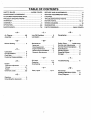
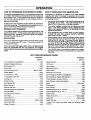
TABLE OF CONTENTS
SAFETY RULES .....................................
MAINTENANCE
CUSTOMER
INSIDE COVER
AGREEMENT ......................................
SERVICE RECOMMENDATIONS
..................................
1
STORAGE .....................................................................
.......................................
RESPONSIBILITIES
PRODUCT SPECIFICATIONS
SERVICE AND ADJUSTMENTS ....................................
1
................................
1
TROUBLESHOOTING
1
REPAIR PARTS .......................................................
ASSEMBLY .....................................................................
3
WIRING DIAGRAM .......................................................
POINTS ...................................
4-6
WARRANTIES .........................................................
MAINTENANCE
7-8
PARTS ORDERING ..................................
...........................................................
Air Cleaner ..............
Assembly ................
4,8
3
-BBefore Starting ............
5
-CCarburetor ................
Circuit Breakers ...........
Cord Sets ................
9
3
3
Customer Responsibilities...
1
9
5,7
9
5,6
Gasoline .................
5
Grounding the Generator ....
3
19-21
BACK COVER
6
5,7
Receptacles..............
3
-S-
Maintenance
Agreement ..................
1
Cleaning generator............
7
Enginemaintenance.........
7-8
GeneralRecommendations..... 7
GeneratorMaintenance........
7
Safety Rules ......
inside cover
Service and Adjustments ....
9
Service Recommendations . 10
-O-
-T5, 7
4-6
6
Specifications .............
Starting Engine ............
Stopping Engine ...........
Storage .................
Troubleshooting ..........
-pParts, repair ...........
1
5
5
10
11
-W12-17
Warranties
............
Wattage Reference Guide...
Wiring Diagram ...........
-G-
18
-M-
Oil Level ...............
Operation ...............
Overloading ..............
-EEngine
Carburetor adjustment .........
Oil level...................
Speed ......................
Electrical Loads ..........
Low Oil Shutdown..........
Lubrication ..............
11
12-17
-R-
L
-A-
10
10
WARRANTY ....................................................................
OPERATION ................................................................
9
19-21
6
18
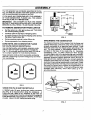
ASSEMBLY
Your AC generator was completely assembled at the factory. It is ready for use after it has been properly serviced
with the recommended lubricating oil and fuel.
4-Wire
IF YOU HAVE ANY PROBLEMS WITH THE ASSEMBLY
OF YOUR GENERATOR, PLEASE CALL THE GENERATOR HELPLINE AT 1-800-222-3136.
Cord Sel
_240V..__
_120V..__._120V..__
IMPORTANT:
ANY ATTEMPT TO RUN THE ENGINE
BEFORE IT HAS BEEN SERVICED WITH THE RECOMMENDED OIL WILL RESULT IN AN ENGINE FAILURE.
TO REMOVE
GENERATOR
FROM CARTON
Set the carton on a flat rigid surface with "THIS SIDE
UP" arrows pointing upward.
bt)_/_7_7
Carefully open the top flaps of shipping carton.
Grounl (Hot)
(Green)
Cut down comers at one end of shipping carton and lay
that side of carton down flat.
FIG. 2
Remove packing material, carton fillers, etc.
Remove generator from shipping carton.
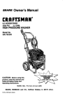
CORD SETS AND CONNECTOR
120 VOLTS
DUPLEX
PLUGS
RECEPTACLE
Use only high quality, well-insulated, extension cords
with the 120-volt =duplex" type electrical receptacles
(Fig. 1). All cord sets used should be rated 125 volts at
15 a-c amps or greater for most electrical devices.
Keep extension cords as short as possible, preferably
less than 15 feet long to prevent voltage drop and wires
from overheating.
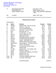
GROUNDING
THE GENERATOR
The National Electrical Code requires that the frame and
external electrically conductive parts of this generator be
properly connected to an approved earth ground. Local
electrical codes may also require proper grounding of the
unit. For that purpose, a GROUNDING WING NUT is
provided on the base of the cradle (Fig. 3). Generally,
connecting a No. 12 AWG (American Wire Gauge)
stranded copper wire to the grounding lug and to an earthdriven copper or brass grounding rod (electrode) provides
adequate protection against electrical shock. Be sure to
keep ground wire attached when you connect electrode.
However, local codes mayvary widely. Consult with a local
electrician for grounding requirements inyourarea. Proper
grounding of generator will help prevent electrical shock in
the event of a ground fault condition in the generator or in
connected electrical devices. Proper grounding also helps
dissipate static electricity, which often builds up in ungrounded devices.
#12AWG
COPPER
STRANDED
WIRE
FIG. 1
i20/240
VOLTS,
20 AMP RECEPTACLE
_GROUNDING
A 120/240 volts, 20 amp, locking type mating connector
plug (Fig. 2) is required when using this receptacle. A
4-wire cord set, rated 20 a-c amperes at 250 volts (or
greater), is required and must be connected to the plug and
to the desired loads. The receptacle is N EMA L14-20R type
of outleL Use a L14-20P mating connector plug.
SCREW
GROUNDING
FIG. 3
ROD
OPERATION
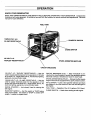
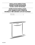
KNOW YOUR GENERATOR
READ THIS OWNER'S MANUAL AND SAFETY RULES BEFORE OPERATING YOUR GENERATOR. Compare the
illustrations with your generator, to familiarize yourself with the locations of various controls and adjustments. Save the
manual for future reference.
FUEL TANK
120/240 VOLT A.C.
RUN/STOP SWITCH
20 AMP RECEPTACLE
CHOKE SWITCH
120 VOLT A.C.
"DUPLEX"
RECEPTACLES
SPARK ARRESTOR
MUFFLER
CIRCUIT BREAKERS
120-VOLT A.C. "DUPLEX" RECEPTACLES m May be
used to supply electrical power for the operation of 120 volts
at 15 amps A.C., single phase, 60 Hz, AC electrical lighting,
appliance, tool and motor loads.
120/240-VOLT A.C., 20 AMP RECEPTACLE -- May be
used to supply electrical power for the operation of 120
and/or 240 volts at 20 amps A.C., single phase, 60 Hz, AC
electrical lighting, appliance, tool and motor loads.
RECOIL STARTER -GN engine.
(not shown) Used for starting the
RUN/STOP SWITCH -- Set this switch to "RUN" before
using recoil starter. Set switch to "STOP" to switch OFF
engine. Located on engine block.
CIRCUIT BREAKERS (A.C.) -- Each receptacle is provided with a circuit breaker to protect the generator against
electrical everload. Breakers are "push to reset" type.
SPARK ARRESTOR MUFFLER -- Exhaust muffler lowers
engine noise and is equipped with a spark arrestor screen.
AIR CLEANER -- Uses a dry type filter element and foam
pre-cleaner to limit the amount of dirt and dust that gets in
the engine.
FUEL TANK --Capacity
of four U.S. gallons (15.2 liters).
CHOKE SWITCH -- Used when starting.a cold engine.
OPERATION
IF YOU HAVE ANY PROBLEMS OPERATING YOUR
GENERATOR,
PLEASE CALL THE GENERATOR
HELPLINE AT 1-800-222-3136.
BEFORE
STARTING
ENGINE
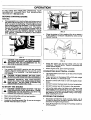
ADD OIL:
Place generator on a level surface and remove one of
the yellow Oil Fill Caps (Fig. 4) and add engine oil until
level is at point of overflowing. Check engine oil level
before starting each time thereafter. If oil level is below
point of overflowing, fill to proper level. The recommended oils include (during summer months) SAE 30
oil. SAE 10W-30 is an acceptable substitute. During
winter months use SAE 5W-20 or 5W-30. DO NOT
USE 10W-40. Crankcase oil capacity is about 620ml
or 21 fluid ounces.
FIG. 5
Close the choke to FULL position (Fig. 6) by sliding it
to far position in direction indicated by arrow on air
cleaner housing.
I I
RUN
r-D--7
I
FIG. 4
CAUTION:
_IL
ANY AI-rEMPT
HALF
TO CRANK OR START
FIG. 6
THE ENGINE BEFORE IT HAS BEEN PROPERLY
SERVICED WITH THE RECOMMENDED
OIL RESULTS IN AN ENGINE FAILURE.
•
Grasp the starter grip and pull slowly until you feel
resistance. Then pull rapidly. Repeat it necessary with
choke opened slightly.
•
When engine starts, open choke gradually.
ADD GASOLINE:
Use regular UNLEADED gasoline with the generator
engine. Regular leaded gasoline may also be used if
UNLEADED is not available. Fuel tank capacity is 4
U.S. gallons.
_k
CONNECTING
CAUTION:ALLOW
ALWAYS
DO NOT
ROOM
OVERFILL
FOR FUEL
THEEXPANSION.
FUEL TANK. [
NEVER FILL FUEL TANK WHEN ENGINE IS RUNNING OR HOT. DO NOT UGHT A ClGARET OR
SMOKE WHEN FILLING FUEL TANK.
TO START
I
Let engine stabilize and warm up for about five minutes
after starting.
•
Plug in and turn on the desired 120 or 240 volts, single
phase, 60 Hertz, a-c electrical loads.
•
DO NOT connect 240 volts to 120 volts duplex receptacles.
•
DO NOT connect 3-phase loads to panel receptacles.
DO NOT connect any 50 Hz loads to the generator.
THE ENGINE
Add up the rated watts of all lights, tool, appliance and
motor loads you are powering at one time. This total
should NOT be greater than (a) generator"_ rated wattage capacity or (b) circuit breaker rating of the receptacle supplying the power.
CAUTION: NEVER START, OR STOP, THE EN- I
GINE-GENERATOR WITH ELECTRICAL LOADS
CONNECTED TO THE RECEPTACLES WITH THE
CONNECTED DEVICES TURNED ON.
I
•
•
Start, store and fuel the unit in a level position.
Open fuel shut-off valve.
•
Locate the Run/Stop switch iFig. 5) next to the engine
cylinder head and set it to RUN.
LOADS
•
WARNING: NEVER FILL FUEL TANK INDOORS. I
A
ELECTRICAL
STOPPING
5
THE ENGINE
•
Disconnect all electrical loads and let engine run at
no-load for about five minutes to stablize intemal temperatures of engine and generator.
•
Turn off the engine by moving the Run/Stop switch to
STOP position.
OPERATION
LOW OIL PRESSURE
SHUTDOWN
SYSTEM
DON'T OVERLOAD
THE GENERATOR
The engine is equipped with a low oil pressure sensor that
shuts down the engine automatically when the oil pressure
drops below 6 psi. If the engine shuts down by itself and
the fuel tank has enough gasoline, check engine oil level.
Overloading a generator in excess of its rated wattage
capacity can result in damage to generator and to connected electrical devices. Observe the following, to prevent
overloading the unit:
INITIAL
•
Add up the total wattage of all electrical devices to be
connected at one time. This total should NOT be
greater than the generator's wattage capacity.
•
The rated wattage of lights can be taken from light
bulbs. The rated wattage of tools, appliances and
motors can usually be found on a data plate or decal
affixed to the device.
•
If the appliance, tool or motor does not give wattage,
mulitply 120 volts times ampere rating to determine
watts (volts x amps = watts).
•
Some electric motors, such as induction types, require
about two-and-a-half times more watts of power for
starting than for running. This surge of power lasts for
only a few seconds when starting such motors. Be sure
you allow for this high starting wattage when selecting
electrical devices to connect to your generator. First
figure the watts needed to start largest motor. Add to
that figure running watts of all other connected loads.
•
The GUIDE below is provided to assist you in determining how many items your generator can operate at
one time.
STARTUP
A delay built in the shutdown system allows oil pressure to
build during starting. The delay allows the engine to run for
about 10 seconds before sensing oil pressure.
SENSING
LOW PRESSURE
If the system senses low oil pressure during operation, the
engine shuts down. As the system shuts down, the low oil
light comes ON. However, once the engine has stopped
rotating, this light will go OFF.
RESTARTING
If you try to restart the engine within 5 seconds after it shuts
down, the engine may NOT start. The system needs 5 to
10 seconds to reset.
If you do restart the engine after such a shutdown and
have not corrected the low oil pressure, the engine
runs for about 10 seconds as described above and then
stops.
WATTAGE
REFERENCE
GUIDE
RUNNING
RUNNING
WATTS
WA'I-I'S
*Air Conditioner (12,000 Btu) ....................................
1700
Impact Wrench ...........................................................
500
Battery Charger (20 amp) ..........................................
500
*Jet Pump ...................................................................
800
Belt Sander (3") .........................................................
1000
Lawn Mower ..............................................................
1200
Chain Saw .................................................................
1200
Microwave Oven .........................................................
700
Circular Saw (6-12/") ..................................... 800 to 1000
Coffee Maker .............................................................
1000
*Milk Cooler ...............................................................
1100
Oil Burner on Fumace ................................................
300
*Compressor (1 HP) ..................................................
2000
Oil Fired Space Heater (140,000 Btu) ........................
400
*Compressor (3/4 HP) ...............................................
1800
Oil Fired Space Heater (85,000 Btu) ..........................
225
Curling Iron .................................................................
700
*Paint Sprayer, Airless (1/3 HP) .................................
600
*Deep Freeze .............................................................
500
Disc Sander (9") ........................................................
1200
Paint Sprayer, Airless (handheld) ............................... 150
Radio ................................................................
50 to 200
Edge Trimmer .............................................................
500
*Refrigerator ...............................................................
600
Electric Nail Gun .......................................................
1200
Slow Cooker ...............................................................
200
Electric Range (one element) ....................................
1500
*Submersible
Pump (1-1/2 HP) .................................
2800
Electric Skillet ............................................................
1250
*Submersible
Pump (1 HP) .......................................
2000
*Furnace Fan (1/3 HP) ..............................................
1200
Sump Pump ................................................................
Hair Dryer ..................................................................
1200
*Table Saw (10") .........................................
Hand Drill (1") ............................................................
1100
Television .........................................................
Hand Drill (1/2") ..............................................
750 to 1000
Hand Drill (3/8") ..........................................................
500
Hedge Trimmer ..........................................................
450
600
1750 to 2000
200 to 500
Weed Trimmer ............................................................
500
* Allow 2-1/2 times the listed watts for starting these
devices.
6
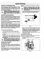
MAINTENANCE
GENERAL
Change oil while engine is still warm from running, as
follows:
RECOMMENDATIONS
The Owner/Operator is responsible for making sure that all
periodic maintenance tasks are completed on a timely
basis; that all discrepancies are corrected; and that the unit
is kept clean and properly stored. Never operate a damaged or defective generator.
CAUTION:
DISCONNECT SPARK PLUG WIRE
CAUTION:
DISCONNECT
SPARK PLUG WIRE
FROM SPARK PLUG AND KEEP IT AWAY FROM
SPARK PLUG. DO THIS EVERYTIME YOU PERFORM ANY MAINTENANCE ON THE ENGINE OR
THE GENERATOR.
•
FROM
SPARK
PLUG
AND PLACE
WIRE
WHERE
IT
CANNOT
COME
IN CONTACT
WITH
YOUR
SPARK
PLUG BEFORE WORKING ON YOUR GENERATOR.
GENERATOR
Clean area around oil drain plug, remove plug ,(Fig. 7)
and drain oil completely into a suitable container.
MAINTENANCE
Generator maintenance consists of keeping the unit clean
and dry. Operate and store the unit in a clean dry enviorment where it will not be exposed to exceesive dust, dirt,
moisture or any corrosive vapors. Cooling air slots in the
generator must not become clogged with snow, leaves or
- any other foreign material.
Check the cleanliness of the generator frequently and clean
when dust, dirt, oil, moisture or other foreign substances
are visible on its exterior surface.
NOTE: We DO NOT recommendusinga garden hose to clean
the generator. Water can enterthe enginefuel systemand cause
problems. In addition, if water enters the generator through
coolingair slots,some of the water will be retained in voidsand
cracksof the rotorand stator windinginsulation. Water and dirt
buildupon the generator internalwindings will eventually decrease the insulationresistanceof thesewindings.
FIG. 7
•
When oil has drained, install and tighten oil drain plug.
•
Remove oil fill plug and insert a clean fill funnel into
plug opening. Fill engine crankcase with recommended oil until oil level is at point of overflowing. Do
not overfill above the point of overflowing. About 21
ounces (620ml) is required. POUR SLOWLY.
A soft, bristle brush may be used to loosen caked on
dirt, oil, etc.
•
When engine crankcase is filled to proper level. Install
and tighten oil fill plug.
A vacuum cleaner may be used to pick up loose dirt
and debris.
RETORQUE
Low pressure air (not to exceed 25 psi) may be used
to blow away dirt. Inspect cooling air slots and opening
on the generator. These openings must be kept clean
and unobstructed.
After 50 hours of operation, retorque the head bolts for the
GN engine to 4.0 kg/m (29 foot-pounds).
TO CLEAN
THE GENERATOR:
Use a damp cloth to wipe exterior surfaces clean.
CAUTION:
NEVER
INSERT
ANY
OBJECT
OR
TOOL
THE
AIRRUNNING.
COOLING SLOTS,
EVEN
IF THETHROUGH
ENGINE IS
NOT
DAMAGE
TO
THE UNIT OR PERSONAL INJURY MAY RESULT.
ENGINE
CHECKING
•
HEAD BOLTS
The torque sequence is A, B, C, D, E (star pattern).
See Fig. 8.
D
B
MAINTENANCE
OIL LEVEL
See OPERATION section on Page 5 for information on
checking oil level. Oil level should be checked before each
use or at least every eight hours of operation. Keep oil level
maintained.
Change oil after first 8 hours of operation. Change oil every
50 hours thereafter. If you are using your generator under
dirty or dusty conditions, or in extremely hot weather,
change oil more often.
E
C
FIG. 8
MAINTENANCE
SERVICE
AIR CLEANER
REPLACE
Your engine will not run properly and may be damaged if
you run it using a dirty air cleaner.
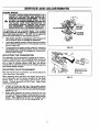
SPARK
PLUG
Change the spark plug every 100 hours of operation or
once each year, whichever comes first. This will help your
engine to start easier and run better. Replace with Champion RC12YC or equivalent type spark plug. Set sparkplug
gap (Fig_ 10) 0.030 inch (0.76mm).
Clean or replace the air cleaner paper filter (Fig. 9) once
every 25 hours of operation or once a year, whichever
comes first. Clean or replace more often if operating under
dusty or dirty conditions. Clean foam pre-filter every 25
hours of operation or sooner under dusty conditions.
CAUTION: NEVER RUN THIS UNIT WITHOUTTHE
0.030" FEELER GAUGE
(0.76ram)
COMPLETE
AIR CLEANER
SYSTEM
INSTALLED
ON THE ENGINE.
THIS COULD
RESULT
IN PREMATURE WEAR TO THE ENGINE.
FIG. 10
CLEAN
SPARK
ARRESTOR
SCREEN
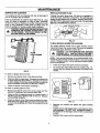
The engine exhaust muffler has a spark arrestor screen.
Inspect and clean the screen every 100 hours of operation
or once each year, whichever comes first.
WORKING ON IT. CONTACT WITH A HOT MUFFLER OR ENGINE CAN CAUSE SEVERE BURNS,
PRECLEANER
PAPER FILTER
NOTE: If you use yourgeneratoron any forest-covered,brushcoveredor grass-coveredunimprovedland, itmusthave a spark
arrestor.The sparkarrestormustbe maintainedingoodcondition
bythe owner/operator.
•
Clean and inspect the spark arrestor as follows:
•
To remove the heat shield from the muffler (Fig. 11),
remove the four screws that connect the sheild to the
muffler.
FIG. 9
To clean or replace foam pre-filter:
•
Remove air cleaner cover, then foam pre-filter.
•
Wash pre-filter in soap water. Squeeze pre-cleaner dry
in clean cloth (DO NOT TWIST). Saturate pre-cleaner
in clean engine oil and then wrap pre-filter in clean dry
cloth to squeeze out excess oil (DO NOT TWIST).
1
•
Clean air cleaner cover before installing it.
To clean or replace paper air filter:
•
Remove air cleaner cover; then remove foam pre-filter
(service if necessary) and remove paper filter.
•
Clean air filter by tapping it gently on a solid surface. If
the filter is too dirty, replace it with a new one. Dispose
of the old filter properly.
•
L_...._
Clean air cleaner cover then insert pre-filter into cover.
Next insert new paper filter into cover to hold pre-filter
in place and assemble all of them to the base of the air
cleaner.
FIG. 11
Remove four screws that attach the spark arrestor
screen.
Inspect screen and replace if tom, perforated or otherwise dama0ed. DO NOT USE a defective screen. If
the screen is not damaged, clean it with a commercial
solvent.
•
8
Reattach the screen and the heat shield.
SERVICE AND ADJUSTMENTS
ENGINE
SPEED
CAUTION: ENGINE SPEED WAS PROPERLY ADJUSTED AT THE FACTORY AND SHOULD REQUIRE NO ADDITIONAL ADJUSTMENT.
DO NOT
_k
ATTEMPT
TO ENGINE
CHANGE IS ENGINE
IF YOU
BEUEVE THE
RUNNINGSPEED.
TOO FAST
OR
TOO SLOW, TAKE YOUR GENERATOR
TO
AUTHORIZED
SERVICE CENTER FOR REPAIR
AND ADJUSTMENT.
CHANGING ENGINE GOVERNED SPEED WILL VOID ENGINE WARRANTY.
FEELER
0 GAUGE
Your generator runs at a constant speed. This constant
operaUng speed is maintained by a mechanical, flyweight
type, fixed speed governor. DO NOT try to adjust the
governed speed setting for the following reasons:
•
High engine speeds are dangerous and increase the
risk of personal injury or damage to equipment.
•
Low engine speeds impose a heavy load on the engine
when sufficient engine power is not available and may
shorten engine life.
•
The generator will supply correct rated AC frequency
and voltage only at the proper speed. Some connected
electrical devices could be damaged by incorrect frequency and/or voltage.
ADJUSTING
',LOOSEN
JAM NUT
FIG. 11
THE CARBURETOR
The carburetor of your generator is preset at the factory.
DO NOT TAMPER WITH THE CARBURETOR, as this will
void the emission control system warranty. If your generator is used at altitudes above 5,000 feet, you should
consult with an authorizes Sears Service Facility regarding
high altitude jetting changes.
ADJUSTING
VALVE
CLEARANCE
After the first 50 hours of operation, you should adjust the
valve clearance in the engine.
When adjusting valve clearance, the engine
room temperature and the piston should be
Center (TDC) of its compression stroke
closed). Correct clearance is 0.05-0.1mm.
clearance as follows:
should be at
at Top Dead
(both valves
Adjust valve
•
Loosen the rocker arm jam nut. Use an allen wrench
to tum the pivot ball stud while checking clearance
between the rocker arm and the valve stem with a feeler
gauge (Fig. 121.
•
When valve clearance is correct, hold pivot ball stud
with allen wrench and tighten rocker arm iam nut with
a crows foot. Tighten the jam nut to 65-85 mch-pounds
torque. After tightening the jam nut, recheck valve
clearance to make sure it did not change (Fig. 13).
FIG. 13
9
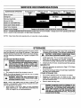
SERVICE RECOMMENDATIONS
MAINTENANCE
OPERATION
Check Oil Level
Every 8 Hours or
Dally
25 Hours or Every
Season
50 Hours or Every
Season
100 Hours or Every
Season
X
Change Oil
Retorque Head Bolts
Service Air Filter
Replace or Clean Spark Plug
Clean Spark Arrestor Screen
AdjustValve Clearance,
PrepareUnitfor Storage
X
Prepare unitfor storageif it is to remainidlefor morethan 30 days.
NOTE 1: Change oil afterfirst8 hoursof operationand then every50 hoursthereafter. Change soonerwhen operatingunderheavy
loador in dusty or dirtyenvironmentor in highambienttemperature.
NOTE 2: Clean more often when operating the unit under dirty or dusty conditions.
STORAGE
The generator should be started at least once every seven
days and allowed to run at least 30 minutes. If this cannot
be done and you must store the unitfor more than 30 days,
use the following information as a guide to prepare it for
storage.
STORAGE
A
•
HOLE WHEN CRANKING ENGINE SLOWLY.
INSTRUCTIONS
WARNING: NEVER STORE ENGINE WITH FUEL IN
THE TANK INDOORS OR IN ENCLOSED, POORLY
VENTILATED
AREAS,
WHERE
FUMES CAN
REACH AN OPEN FLAME SPARK OR PILOT LIGHT
AS ON A FURNACE, WATER HEATER, CLOTHES
DRYER OR OTHER GAS FURNACE.
•
Clean dirt, oil and grease from cylinder, cylinder head,
fins, blower housing, rotating screen and muffler area.
•
Close fuel shut-off valve, located beneath the fuel tank.
Clean the generator as outlined on Page 7 ("To Clean
the Generator').
•
Check that coolingair slots and openings on generator
are open and unobstructed.
OTHER STORAGE TIPS
Run engine for about five minutes to warm it.
WARNING:
DRAIN FUEL INTO APPROVED CONTAINER OUTDOORS, AWAY FROM OPEN FLAME.
BE SURE ENGINE IS COOL
NOTE: Using a fuel additive such as Sears Craftsman® Fuel
Stabilizer,or an equivalent,willpreventgum depositsfrom formingin the generator'sfuel system.
•
Install spark plug. Do not connect spark plug wire.
•
NOTE: If you did use "gasohol," drain fuel tank, then run engine
until engine stops from lack of fuel.
A
•
GENERATOR
ENGINE
•
Remove spark plug and pour about 1/2 ounce (15ml)
of engine oil into cylinder. Crank slowly to distribute oil.
While engine is still warm, drain oil from crankcase.
Refill with fresh oil. See BEFORE STARTING ENGINE on Page 5 for oil recommendations.
•
Do not store gasoline from one season to another.
•
Replace your gasoline can if it starts to rust. Rust
and/or dirt in your gasoline can cause problems when
you use it with this unit.
•
Store in clean and dry area.
A
]0
DANGER: STORAGE COVER IS FLAMMABLE. DO
NOT PLACE THE STORAGE COVER OVER A HOT
GENERATOR. LET THE UNIT COOL FOR A SUFFb
CIENT TIME BEFORE PLACING THE COVER ON
THE UNIT. IF YOU PLACE THE COVER ON THE
UNIT BEFORE GENERATOR IS COOL, THE COVER
COULD START ON FIRE.
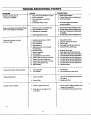
TROUBLESHOOTING
PROBLFM
POINTS
CORRECTION
CAUSE
Engine is running, but no
1.
One of the circuit breakers is open.
AC output is available.
2. Fault in generator.
3. Poor connection or defective
cord set.
4. Connected device is bad.
1. Reset circuit breaker.
2. Contact Sears Service Department.
3. Check and repair.
4. Connectanotherdevice thatis
in goodcondition.
Enginerunsgoodat no-loadbut "bogs
down"when loadsare connected
Enginewill not start;or starts
and runsrough.
2. Engine speed is too slow.
1. Disconnect shorted electrical load.
2. Contact Sears Service Department.
3. Generatoris overloaded.
3. See "Don'tOvedoadthe Generator
4. Shortedgeneratorcircuit.
on Page 6.
4. ContactSearsService Department.
1. Short circuit in a connected
1.
2.
3.
4.
5.
Run/StopSwitchset to STOP.
Dirtyair cleaner
Out of gasoline.
Stale gasoline.
Spark plugwire notconnected
to spark plug.
6. Bad spark plug.
7. Water in gasoline.
8. Overchoking.
go
10.
11.
12.
13.
14.
Engine shuts down during operation
1.
2.
Enginelackspower.
Engine"hunts"or falters.
load.
Excessively rich fuel mixture.
Intake valve stuck open or dosed.
Engine has lost compression.
Intake valve stuck open or closed.
Engine compression lost.
Failed battery.
Out of gasoline.
Low oil level,
1. Set switch to RUN.
2. Clean or replace air cleaner.
3. Fill fuel tank.
4. Drain gas tank; fill with fresh fuel.
5. Connect wire to spark plug.
6. Replace spark plug.
7. Drain gas tank; fill with fresh fuel.
8. Open choke fully and crank engine.
9. Contact Sears Service Department.
10.
11.
12,
13.
14.
Contact Sears Service
Contact Sears Service
Contact Sears Service
Contact Sears Service
Replace battery.
Department.
Department.
Department.
Department.
1.
Fill fuel tank.
2.
Fill crankcase to proper level.
2. Dirty air filter.
1. See =Don'tOvedoadthe Generator"
on Page 6.
2. Replaceair filter.
1. Choke is opened too soon.
1. Move choke to halfway position until
1. Load is too high.
2. Carburetor is running too rich
or too lean.
It
engine runs smoothly.
2. Contact Sears Service Department.
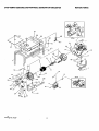
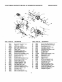
CRAFTSMAN
3250 DELUXE
PORTABLE
GENERATOR
580.326720
REPAIR
PARTS
61
I0
66
DETAIL
" X"
._
SEE
DETAIL"
Y"
43
10
12
18
1
3
11
74
DETAIL
Drawing
No. 97229
12
" Y "
CRAFTSMAN
ITEM
1
2
3
4
5
6
7
8
9
10
11
12
13
16
17
18
19
20
21
22
23
25
26
27
30
32
33
34
35
36
37
38
39
41
42
43
44
46
47
48
49
50
51
52
53
54
55
56
58
60
61
62
64
66
67
68
69
70
71
72
73
74
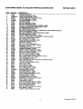
3250XL
AC DELUXE
PORTABLE
GENERATOR
REPAIR
PARTS
DESCRIPTION
PART NO.
CRADLE-XL (1REQ,)
97196
ENGINE SUPPORT (1 REQo)
84021
GN191 6.5HP ENGINE (1 REQ.)
ENG98701
ENGINE ADAPTOR HOUSING (1 REQ,)
66365
ROTOR ASSEMBLY (1 REQ.)
84141G
STATOR ASSEMBLY (1 REQ.)
91838G
65791
BEARING (1REQ.)
M8 FLAT WASHER (1 REQ.)
67451
M8 LOCK WASHER (2 REQ.)
22129
5/16-24 X 3/4 HEX HEAD MACH. SCREW (4 REQ.)
86307
5/16-24 X 6.5" HEX HEAD CAP SCREW (1 REQ.)
52122
45 ° VIBRATION MOUNT (2 REQ.)
84508
52858
M8 LOCKING NUT (8 REQ.)
M6-1.00 X 12 HEX HEAD MACH. SCREW WITH LOCK WASHER (2 REQ.)
66476
MUFFLER ASSEMBLY (1 REQ.)
88688
M8-1.25 X 20 SOCKET HEAD CAPSCREW (2 REQ.)
40976
EXHAUST GASKET (1 REQ.)
89476
SPARK ARRESTOR SCREEN (1 REQ.)
83083
M4-0.7 X 10 PHILLIPS PAN HEAD MACH. SCREW (4 REQ.)
75475
CONTROL PANEL DECAL (1 REQ.)
98247
M4 X 10 ROLL PIN (1 REQ.)
81917
REAR BEARING CARRIER (1 REQ.)
66825B
VIBRATION MOUNT (2 REQ.)
85652
M8 HEX NUT (2 REQ.)
45771
M5-O.8 X 10 TAPTITE (4 REQ.)
74908
M6-1.0 X 115 STATOR BOLT (4 REQ.)
86308
GROMMET (2 REQ.)
84242
#8 SHAKEPROOF WASHER (4 REQ.)
23365
RUBBER GROMMET (1 REQ.)
67022
20AMP. CIRCUIT BREAKER (1 REQ.)
94396B
BRUSH HOLDER ASSEMBLY (1 REQ.)
91825
M5-0.7 X 16 TAPTITE (2 REQ.)
66849
CONTROL PANEL COVER (1 REQ.)
95600
M6-1.0 X 16 WING SCREW (1 REQ.)
86494
#10 x 16 SELF DRILLING CAP SCREW (1 REQ.)
86292
M6 FLANGE LOCK NUT (4 REQ.)
77395
TANK GROMMET (4 REQ.)
83465
M6-1.0 X 60 (BLACK) HEX HEAD MACH. SCREW (4 REQ.)
78831B
TANK VALVE (1 REQ.)
80270
PLASTIC TANK BUSHING (1 REQ.)
78299
FUEL CAP (1 REQ.)
85134
83311
FUELTANK (1 REQ.)
HEAT SHIELD (1 REQ.)
84042
#2 1/4" INSULATION (1 REQ.)
84687
CLIP INSULATION (1 REQ.)
65000
GROUND WIRE (1 REQ.)
143-53621
#10 SHAKEPROOF (1 REQ.)
23762
M6 SHAKEPROOF (1 REQ,)
26850
15AMP CIRCUIT BREAKER (1 REQ.)
94396A
#8 FLAT WASHER (4 REQ.)
381 50
DANGER DECAL (1 REQ.)
92982
HEAT SHIELD DECAL (2 REQ.)
98703
EMISSION CONTROL DECAL (1 REQ.)
94603B
START DECAL (1 REQ.)
93826
1-800 DECAL (1 REQ.)
96409
MUFFLER WARNING DECAL (1 REQ.)
77816
DATA SHEET CODE DECAL (1 REQ.)
98717
#8 LOCK WASHER (4 REQ.)
22264
M4-0.7 HEX NUT (4 REQ.)
51715
120V. 20A, DUPLEX OUTLET (1 REQ.)
68759
77026
DATA DECAL (1REQ.)
120/240V. 20A TWISTLOCK (1 REQ.)
68867
13
Drawing
No. 97229
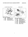
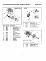
CRAFTSMAN
3250 WATT DELUXE
AC GENERATOR
580.326720
REPAIR
PARTS
RECOIL STARTER
OIL SWITCH AND OIL BLOCKOFF
9!
82
lJ 8g
\
84
86
5
NO
REM
1
2
3
4
5
88
OIL FILTER
PART NO.
DESCRIPTION
94820
91848
88758
92978
99236
EXPANSION PLUG (1 REQ.)
OIL FILTERGASKET (1 REQ.)
OIL BLOCKOFF (1 REQ.)
M6 x 20ram SCREW (2 REQ.)
OIL PRESSURESWITCH (1 REQ.)
ITEM
82
83
84
85
86
87
88
89
9O
91
14
PART NO.
DESCRIPTION
92984
45756
78609
78608B
90695A
89739
66476
95268
83015
78651C
TOP WRAPPER (1 REQ.)
M6 x lOmm SCREW (4 REQ.)
COVER BOLT (2 REQ.)
SEARSAIR BOX COVER (I REQ.)
BLOWER HOUSING (1 REQ.)
LOWER WRAPPER (I REQ.)
M6 x 12mm CAPSCREW (9 REQ.)
RECOIL ASSEMBLY (I REQ.)
RECOIL CUP (I REQ.)
BACKPLATE (I REQ.)
CRAFTSMAN
3250 WATT DELUXE
GREEN
AC GENERATOR
580.326720
REPAIR
PARTS
14
25B
21
9
!
2O
29
28
5O
ITEM
7
PART NO.
DESCRIPTION
78653
Run/Stop Switch (1 req.)
PART NO.
QTY.
20
72347
21
86962
Spark Plug, (1 req.)
Governor Lever (1 req.)
22
85953
Wear Washer (1 req.)
83502
83512
Adjust Screw (1 req.)
M8 x 15mrn Taptite
ITEM
8
9
85272
84195
L.E.D. Assembly (1 req.)
Low Oil Shutdown Decal (1 req.)
10
85620
Black Sleeving (1 req.)
23
12
84329
3-pin Male Connector
24
13
00185271
Housing (1 req.)
White Wire Assembly (1 req.)
25
14
22097
M6 Lock Washer (2 req.)
15
16
82891
81675
17
18
19
DESCRIPTION
Screw (1 req.)
Governor Spring (1 req.)
26
78604
66476
M6 x 30ram Screw (2 req.)
27
83503
28
83781
84274
87221A
Ignition Coil (1 req.)
Tinnerman Clamp (1 req.)
Low Oil Shutdown
M5 Lock Nut (1 req.)
Governor Bracket (1 req.)
29
30
86384
Governor Rod (1 req.)
86037
Anti-lash
45756
Module (1 req.)
M6 x 10mm Screw (1 req.)
M6 x 12mm Capscrew (1 req.)
Spring (1 req.)
..p
15
CRAFTSMAN
3250 WAn" DELUXE
AC GENERATOR
580.326720
REPAIR
PARTS
5
26
1:-
17
33
13
18
ITEM
1
2
3
4
5
6
7
8
9
10
11
12
13
14
15
16
17
18
19
20
21
22
23
24
25
26
PART NO.
78621
76389
78660
89665A
77168
90325
76390
83337
78658
78659
89213B
76354
81695
76359
78645
76365
72683
98752
89096
88156
217041
78691
76367
76362
78692
78606
DESCRIPTION
Control Rod
Piston Pin
Piston Ring
Gear Cover
M8 x 52ram
Assembly (1 req.)
(1 req.)
Set (1 req.)
Assembly (1 req.)
Head Bolt (5 req.)
Piston (1 req.)
Pin Retainer Ring (2 req.)
Crankshaft Assembly (1 req.)
Governor "R" Pin (1 req.)
Governor Arm ThrustWasher (1 req.)
Crankcase Assembly (1 req.)
Governor Arm (1 req.)
Oil Seal (1 req.)
Governor Gear Assembly (1 req.)
Governor Gear C-Ring (1 req.)
Governor Spool (1 req.)
1/8" NPT Pipe Plug (1 req.)
Camshaft Assembly (1 req.)
Crankcase Gasket (1 req.)
Valve Stem Seal (1 req.)
Cylinder Head Gasket (1 req.)
Oil Pressure Relief Cover (1 req.)
Oil Pressure Spring (1 req.)
5/16" Ball (1 req.)
M5 Form Screw (1 req.)
M6-1.0 x 12mm Screw (4 req.)
ITEM
.27
28
29
30
31
32
33
34
35
36
37
38
39
40
41
42
43
44
45
46
47
46
49
16
PART NO.
76361
89230
99922
86293
88401
84186
83192
86254
76349
21705B
90082
90O81
88396A
83235
80336
88397
77161
77160
76307
884O3
72657
88412
76329
21942
DESCRIPTION
Governor GearThrust Washer (1 req.)
M8-1.25 x 35ram Screw (6 req.)
Spring Washer (1 req.)
Valve Spring Retainer (1 req.)
Valve Spring (2 req.)
Valve SpringWear Washer (2 req.)
Geroter Set (1 req.)
"O" Ring (1 req.)
Bearing (1 req.)
Cytinder Head Assembly (1 req.)
Exhaust Valve (1 req.)
Intake Valve (1 req.)
Push Rod (1 req.)
Tappet (2 req.)
Oil Pick-up Assembly (1 req,)
Rocker Cover Gasket (1 req,)
Pivot Ball Stud (2 req.)
Rocker Arm (2 req,)
Rocker Arm Jam Nut (2 req.)
Push Rod Guide Plate (1 req.)
114" NPT Pipe Plug (1 req.)
Rocker Cover Assembly (1 req.)
Plastic Oil Fill Plug (1 req.)
Complete Long Block
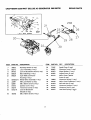
CRAFTSMAN
3250 WATT DELUXE
AC GENERATOR
580.326720
REPAIR PARTS
MUFFLER
CARBURETORAND AIR
CLEANER
\\
43
45
47
'
48
36
/
39
76
44 50
ITEM
PART NO.
DESCRIPTION
89476
40976
88688
66476
83038
Muffler Gasket (1 req.)
M8 x 20mm Capscrew (2 req.)
Small Muffler (1 req.)
M6 x 12 HHFS (2 req.)
41
ITEM
PART NO.
73
74
75
76
DESCRIPTION
31
32
35
36
39
90947
9OO51
80316
90948
91846
1
1
2
1
1
41
42
80303
78631
1
1
43
44
45
46
47
48
49
98469
78607
66476
59635
78601
78602
83504
1
1
1
1
1
1
1
Breather Hose
Manifold
Head Gasket
M6 x 30ram Screw
Intake Manifold
Carburetor/Air
Box
Gasket
Canal Cover
Carburetor
Manifold
Gasket
Carburetor (190cc)
Air Cleaner Base
M6 x 12ram Capscrew
#8 x 3/8" Plastite Screw
Air Filter
Precleaner
Choke Knob
Spark Arrestor (not shown)
79
8O
SEE ITEM 90 ON TRIM
(SHEET METAL) DRAWING
ITEM
78
79
80
81
17
PART NO.
DESCRIPTION
82774
77182E
83312
81810
Woodruff Key (1 req.)
Flywheel (1 req.)
Conical Washer (1 re_)
M16 Hex Nut (1 req.)
/
81
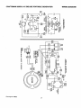
CRAFTSMAN
3250XL
A-C DELUXE
PORTABLE
GENERATOR
WIRING
o
<
Drawing No. 94998
18
DIAGRAM
TWO-YEAR
LIMITED
WARRANTY
FOR DELUXE
PORTABLE
GENERA TORS
SEARS warrants to the original purchaser that the altemator and engine for its portable generator will
be free from defects in
materials or workmanship for the items and period set forth below from the date of original purchase. This warranty is not
transferable and applies only to portable generators driven by the GN-Series Sears warranted engine.
CONSUMER*
Alternator
Engine
COMMERCIAL*
2 years (2nd year parts only)
2 years (2nd year parts only)
I year
1 year
* NOTE: For the purpose of this warranty "consumer
use" means personal residerttlal household use by original
purchaser.
"Commercial Use" means all other uses, including
rental, construction,
commercial and Income
producing purposes.
Once a generator has experienced commercial
use, it shall thereafter be considered
a
commercial use generator for the purposes of this warranty.
During said warranty period, SEARS will, at its option, repair or replace any part which, upon examination by SEARS, is found
to be defective under normal use and service**. Starting batteries are not warranted by SEARS. All transportation costs
under warranty, including retum to the factory if necessary, are to be berne by the purchaser and prepaid by him. This warranty
does not cover normal maintenance and service and does not apply to a generator set, alternator or engine, or parts which
have been subjected to improper or unauthorized installation or alteration, misuse, negligence, accident, overloading,
overspeeding, improper maintenance, repair or storage so as, in SEARS's judgment, to adversely affect its performance and
reliability.
** NORMAL WEAR: As with all mechanical devices, engines need periodic parts service and replacement to peform
well. This warranty will not cover repair when normal use has exhausted the life of a part or an engine.
THERE IS NO OTHER EXPRESS WARRANTY. SEARS HEREBY DISCLAIMS ANY AND ALL IMPLIED WARRANTIES,
INCLUDING BUT NOT LIMITED TO THOSE OF MERCHANTABILITYAND FITNESS FOR A PARTICULARPURPOSE TO
THE EXTENT PERMITTED BY LAW. THE DURATION OF ANY IMPLIED WARRANTIES WHICH CANNOT BE DISCLAIMED IS LIMITED TO THE TIME PERIOD AS SPECIFIED IN THE EXPRESS WARRANTY. LIABILITY FOR CONSEQUENTIAL, INCIDENTAL, OR SPECIAL DAMAGES UNDER ANY AND ALL WARRANTIES IS EXCLUDED. Some states
do not allowlimitationson how long an impliedwarrantylasts, or the exclusionor limitationof incidentalor consequential
damages,sothe above limitationsor exclusionsmay not applytoyou. This warrantygivesyou specificlegal rights and you
may also have otherrights,whichvary from state to state.
For service, see your nearest SEARS authorized warranty service facility. Warranty service can be performed only by a
SEARS authorized service facility. This warranty will not apply to service at any other facility. At the time of requesting
warranty service, evidence of original purchase date must be presented.
SEARS, ROEBUCK AND CO.
Department 817 WA
Hoffman Estates, IL 60179
]9
FOR CALIFORNIA RESIDENTS ONLY WHEN SEEKING SERVICE IN CALIFORNIA
CALIFORNIA
EMISSION
CONTROL
YOUR WARRANTY
RIGHTS
WARRANTY
STATEMENT
AND OBLIGATIONS
The California Air Resources Board and Sears Roebuck and Co., USA (Sears), are pleased to explain the
emissions control system warranty on your 1995 and later lawn and garden equipment engine. In California new
utility and lawn and garden equipment engines must be designed, built, and equipped to meet the State's stringent
anti-smog standards. Sears must warrant the emission control system on your lawn and garden equipment
engine for the periods of time listed below provided there has been no abuse, neglect, or improper maintenance
of your lawn and garden equipment engine.
Your emission control system includes parts such as the carburetor and the ignition system.
Where a warrantable condition exists, Sears will repair your lawn and garden equipment engine at no cost to
you. Expenses covered under warranty include diagnosis, parts, and labor.
MANUFACTURER'S
WARRANTY
COVERAGE
The 1995 and later utility and lawn and garden equipment engines are warranted for two years. If any emission
related part on your engine (as listed below) is defective, the part will be repaired or replaced by Sears.
OWNER'S
WARRANTY
RESPONSIBILITIES
As the lawn and garden equipment engine owner, you are responsible for the performance of the required
maintenance listed in your Owner's Manual. Sears recommends that you retain all receipts covering maintenance
on your lawn and garden equipment engine, but Sears cannot deny warranty solely for the lack of receipts or for
your failure to ensure the performance of all scheduled maintenance.
As the lawn and garden equipment engine owner, you should be aware that Sears may deny you warranty
coverage if your lawn and garden equipment engine or a part of it has failed due to abuse, neglect, improper
maintenance, unapproved modifications, or the use of parts not made or approved by the original equipment
manufacturer.
You are responsible for presenting your lawn and garden equipment engine to a Sears authorized repair center
as soon as a problem exists. Warranty repairs should be completed in a reasonable amount of time, not to exceed
30 days.
If you have any questions regarding your warranty rights and responsibilities, you should contact your nearest
authorized service center or call Sears at 1-800-473-7247.
WARRANTY
COMMENCEMENT
DATE
_ The warranty period begins on the date the lawn and garden equipment engine is delivered to the original, end-use
purchaser.
LENGTH
OF COVERAGE
Sears warrants to the initialowner and each subsequent purchaser that the engine isfree from defects in materials
and workmanship which cause the failure of a warranted part for a period of two years.
20
WHAT
IS COVERED
REPAIR OR REPLACEMENT
OF PARTS
•
Repair or replacement of any warranted part will be performed at not charge to the owner at an approved
Sears servicing center.
•
If you have any questions regarding your warranty rights and responsibilities, you should contact your nearest
authorized service center or call Sears at 1-800-473-7247.
WARRANTY PERIOD
Any warranted part which is not scheduled for replacement as required maintenance, or which is scheduled only
for regular inspection to the effect of =repair or replace as necessa_ shall be warranted for 2 years. Any warranted
part which is scheduled for replacement as required maintenance shall be warranted for the period of time up to
the first scheduled replacement point for that part.
DIAGNOSIS
The owner shall not be charged for diagnostic labor which leads to the determination that a warranted part is
defective if the diagnostic work is performed at an approved Sears servicing center.
CONSEQUENTIAL DAMAGES
Sears may be liable for damages to other engine components caused by the failure of a warranted part still under
warranty.
WHAT IS NOT COVERED
All failures caused by abuse, neglect,or impropermaintenanceare not covered.
ADD-ON OR MODIFIED PARTS
The use of add-on or modified parts can be grounds for disallowing a warranty claim. Sears is not liable to cover
failures of warranted parts caused by the use of add-on or modified parts.
HOW TO FILE A CLAIM
If you have any questions regarding your warranty rights and responsibilities, you should contact your nearest
authorized service center or call Sears at 1-800-473-7247.
WHERE TO GET WARRANTY
SERVICE
Warrantyservicesor repairsshall be providedat all Sears authorizedservicecenters.
MAINTENANCE,
REPLACEMENT
AND REPAIR
OF EMISSION
RELATED
PARTS
Any Sears approved replacement part used in the performance of any warranty maintenance or repair on emission
related parts will be provided without charge to the owner if the part is under warranty.
EMISSION
CONTROL
WARRANTY
PARTS
LIST
1. Carburetor Assembly
2. Ignition System
a. Spark Plug, covered up to maintenance schedule.
b. Ignition Module
3. Crankcase Breather Tube
4. Exhaust Manifold
21
CRAFTSMAN°
120/240 VOLTS / 3250 WATT A-C
OWNER'S
MANUAL
DELUXE PORTABLE
MODEL No.
580.326720
GENERATOR
Each Portable Generator has its own model number. Each engine has its
own part number.
The model number for your Portable Generator will be found on a decal
attached to the unit.
The part number for your engine will be found on the Blower Housing of
the engine adjacent to the spark plug.
IF YOU NEED
All parts listed herein may be ordered through Sears, Roebuck and Co.
Service Centers and most Retail Stores.
REPAIR SERVICE
OR PARTS
WHEN ORDERING
REPAIR
LOWING INFORMATION:
FOR REPAIR SERVICE CALL
THIS TOLL FREE NUMBER
1-800-4° R EPAl R
(1-800-473-7247)
m
PARTS,
•
PRODUCT
PORTABLE
•
MODEL
•
PART NUMBER
•
PART DESCRIPTION
NUMBER--
ALWAYS
GIVE THE FOL-
GENERATOR
580.326720
FOR REPLACEMENT PARTS INFORMATION AND ORDERING,
CALL THIS TOLL FREE NUMBER:
1-800-FON-PART
Your Sears merchandise has added value when you consider that Sears
has service units nationwide staffed with Sears trained technicians....professional technicians specifically trained on Sears products, having the
parts, tools and the equipment to ensure that we meet our pledge to you,
we service what we sell.
(1-800-366-7278)
SEARS
Part No. 97228 Revision
ROEBUCK
2 (1117/96)
and CO., Hoffman
Estates, IL 60179 U.S.A.
Printed in U.S.A.