1
Extreme Networks Technical Brief
SummitStack Stacking Technology
Introduction
Extreme Networks® SummitStack™ stacking technology
enables the physical connection of up to eight individual
Summit® switches together as a single logical unit. This
logical unit reduces the management overhead of fixed
configuration switches by behaving as a single switch with a
single IP address and a single point of authentication. In
ExtremeXOS®, Extreme Networks edge-to-core modular
operating system, a stack is controlled by a master switch,
called the master. The master switch runs the full-featured
version of ExtremeXOS and is responsible for maintaining
all of the software tables for all the switches in the stack.
There can only be one master switch in a stack of switches.
All switches in the stack, including the master switch, are
called nodes.
A stack of Summit switches can be thought of as a Virtual
Chassis™. Each node acts as if it was occupying a slot in a
chassis and is controlled by the master. The high-speed
stacking links function like the backplane links of a chassis.
Stacking offers customers a flexible way to increase switch
density and capacity, provides port configuration choices, and
controls upfront capital requirements. SummitStack permits
mixing and matching Summit switches in a multi-platform
stack to provide the port configuration you need, from
Ethernet, Fast Ethernet, Gigabit Ethernet to 10 Gigabit
Ethernet, in copper, Power over Ethernet (PoE), Power over
Ethernet Plus (PoE-plus) and fiber optic interfaces.
The master switch stores any configuration information for
the stack in its primary and secondary flash memory. Since
the master switch has the knowledge of the state and the
configuration of all the other switches in the stack, it can
respond to all external requests for those switches. For
example, the master switch can respond to a request for
SNMP information from all ports within the stack.
SummitStack is supported through dedicated stacking port
functionality with specific stack cables or through the use of
existing 10 Gigabit Ethernet ports to stack the switches
together. The latter option allows for physical flexibility
when stacking needs to be carried over longer distances
than is supported in the dedicated stacking cables.
SummitStack is an Extreme Networks solution for fixed
configuration switches to provide simplified yet agile
operations for scalable converged networks. The mechanism supports many network topology designs and is
Ethernet based requiring no new hardware or interfaces.
This technology brief introduces different varieties of
stacking and can help clarify areas of potential confusion.
Topics covered include: different topologies possible with
stacking, aspects of configuring and managing a stack, what
happens during stack topology changes, and how to
configure a stack for the first time.
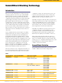
SummitStack Varieties
The following table shows the different stacking options
available on Extreme Networks stacking products.
Table 1
Stacking Options
Speed per Link (HDX)
Cable Type & Lengths
Summit Switch Series
SummitStack
10 Gbps
0.5m, 1.5m, 3.0m
20Gbps Stacking Cable
Summit
Summit
Summit
Summit
Summit
Summit
X250
X450a
X450e
X460
X480
X650
SummitStack-V
10 Gbps
0.5m – 100m
SFP+, XFP, XENPAK, 10GBaseT
Summit
Summit
Summit
Summit
Summit
X450a
X450e
X460
X480
X650
SummitStack-V80 20 Gbps
0.5m – 100m
QSFP+ only
Summit X460
SummitStack128
32 Gbps
0.5m, 1.0m, 3.0m
Summit X480 with conversion
cable to SummitStack256
SummitStack256
64 Gbps
0.5m, 1.0m, 3.0m
Summit X650
SummitStack512
128 Gbps
0.5m, 1.0m, 3.0m
Summit X650
© 2010 Extreme Networks, Inc. All rights reserved.
SummitStack Stacking Technology—Page 1
Extreme Networks Technical Brief
SummitStack Topologies
Ring Topology
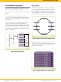
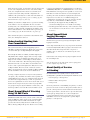
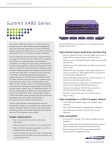
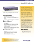
Figure 1 presents a graphical representation of a stack and
some of the terms that describe stack conditions.
A stack is the collection of all nodes that are cabled together
in a stack.
SummitStack nodes should be connected to each other in a
ring topology. In a ring topology, one link is used to connect
to a node and the other link is used to connect to another
node. The result forms a physical ring connection. This
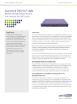
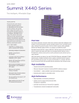
topology is highly recommended for normal operation. Figure
2 shows a maximal ring topology of eight active nodes.
A stack topology is the set of contiguous nodes that are
powered up and communicating with each other. Switch 8 is
not part of the stack topology in Figure 1 because it is not
powered up.
An active topology is the set of contiguous nodes that are
active. An active node is powered up, configured for
SummitStack operation, and communicating with the other
active nodes. Switch 5 in Figure 1 has failed, and stacking is
disabled on Switch 6 and Switch 7. Switch 8 has no power,
so the active topology includes switches: Switch 1, Switch 2,
Switch 3, and Switch 4.
Active
Topology
Stack
Topology
Stack
Switch 1
s
Switch 2
s
Switch 3
5334-01
s
Switch 4
s
Switch 5
s
Switch 6
s
Switch 7
s
Figure 2: Graphical Representation of Ring Topology
s
Failed Node
SummitStack™
Disabled
SummitStack
Disabled
No Power
Switch 8
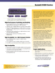
While a physical ring connection may be present, a ring
active topology only exists if all nodes in the stack are active
nodes. Figure 3 shows eight active Summit X450e series
switches in an ring topology.
5333-01
Figure 1: Stack and Topologies
Figure 3: Summit X450e Series in a Ring Topology
© 2010 Extreme Networks, Inc. All rights reserved.
SummitStack Stacking Technology—Page 2
Extreme Networks Technical Brief
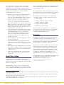
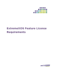
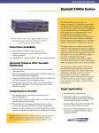
Daisy-Chain Topology
Stackable switches may be connected in a daisy-chain topology. This is a ring topology with one of the links disconnected, inoperative, or disabled. A daisy chain can be
created when a link fails or a node reboots in a ring
topology, but the daisy-chain topology is not recommended
for normal operation. In Figure 4, the nodes delineated as
the active topology are operating in a daisy-chain configuration, even though there is physically a ring connection in
the stack.
Understanding SummitStack
Configuration Parameters,
Configuration Files, and
Port Numbering
Stacking configurations are stored in the NVRAM of each
node. Some of these configurations take effect only during
the next node restart. See Table 2 for stacking configuration
items, times of effect and default values.
Stacking parameters, such as mode, slot number, etc., can
be configured from a single unit in the stack topology. You
can change the stacking-specific configuration even when a
node is not in stacking mode but is connected to the stack.
The target node for the configuration must be powered on
and running a version of ExtremeXOS that supports
stacking. Further, the node need not be in stacking mode
and can be in any node role.
Most ExtremeXOS configuration parameters are not stored
in NVRAM, but are instead stored in a configuration file.
Configurations stored in NVRAM are those that are needed
when the configuration file is not available. The configuration file chosen for the stack is the one selected on the
master node that is first elected after a stack restart.
Table 2: Stacking Configuration Items, Time of Effect
and Default Value
Figure 4: Summit X250e Series in
Daisy-Chain Topology
Configuration Item
Takes Effect
Default Value
Stacking Mode
At boot time
Disabled
Stack Depth
Slot Number
At boot time
1
Master-Capable
At boot time
Yes
A maximum of eight nodes are supported in the active
topology. The slot number configuration assigns only
numbers from one to eight.
License Registration
At boot time
Not configured
The stack tolerates an accidental connection of up to 17
nodes. Because only eight nodes can join an active topology,
there should never be an accidental connection of two
stacks resulting in more than 16 nodes. If you have more
than 17 nodes in a stack topology, all nodes enter an
overflow state and all stacking links enter a link overflow
state. While in an overflow state, the active topology does
not function. All slots containing active nodes show a failed
state. The overflow state is maintained until the overflow is
cleared by manually disconnecting a sufficient number of
nodes. After the overflow is cleared all nodes in the stack
topology reboot.
To see all the nodes in a stack topology, use the show
stacking command.
© 2010 Extreme Networks, Inc. All rights reserved.
Priority
At the next master election
Automatic
Alternate IP Address
Immediately
Not configured
Stack MAC
At boot time
Not configured
The data (non-stacking) port numbers, in the existing
configuration files (which were created when not in
stacking mode), are simple integer quantities. On a stack,
the data port numbers are expressed as slot:port where the
slot is an integer representing the slot and port is an integer
representing the port, for example: 1:2. The configuration
file contains an indication that it was created on a stackable
switch in stacking mode. The indication is the stacking
platform ID.
Thus when in stacking mode, the ports are referenced in the
configuration file with the slot:port notation and when not in
stacking mode, the ports are referenced as simple integers.
SummitStack Stacking Technology—Page 3
Extreme Networks Technical Brief
When the stack restarts, if a switch becomes the master and
its selected configuration file was not created in stacking
mode, the configuration file is deselected, and the stack
completes its restart using a default configuration. In
addition, if the previously selected file was named with one
of the default names (primary.cfg or secondary.cfg), the
file is renamed to old_non_stack.cfg.
topologies and will allow for standard interface media such
as XENPAK, XFP, SFP+ or 10GBASE-T RJ45 to create stack
links. With this technology it is now possible to create stack
links that are much more than five meters in length, and
stacking can now be used between physical locations. It is
important to note that once a 10 GbE stacking port is
configured into stacking mode, the port cannot be used for
any other use, and is unusable for Ethernet traffic.
Similarly, if a switch is configured not to operate in stacking
mode and the selected configuration file was created in
stacking mode, the configuration file is deselected, and the
switch boots with a default configuration. In addition, if the
file was named with one of the default names (primary.cfg
or secondary.cfg), the file is renamed to old_stack.cfg.
• Stacking is only supported using 10 GbE ports.
(10/100/1000 Mbps ports are not usable for stacking)
The renamed file replaces any file that exists with the same
name; the existing file is deleted.
Understanding Stacking Link
Over Commitment
The stack is formed by each node supplying a pair of
full-duplex 10 Gbps stacking ports. Each node can operate
on a stack with up to 20 Gbps full duplex throughput.
Even though two links are available, the links might not be
fully utilized. For example, suppose there is a ring of eight
nodes and the nodes are numbered clockwise from 1 to 8.
Suppose node 1 wants to send 10 Gbps of unicast traffic to
each of node 2 and node 3. The shortest path topology forces
all traffic from node 1 over the link to node 2. Traffic from
node 1 to node 3 passes through node 2. Thus, there is only
10 Gbps available. However, if node 1 wanted to send 10
Gbps to node 2 and node 8, there would be 20 Gbps available
because both links connected to node 1 would be used.
In a ring of eight nodes, between any two nodes (with one
exception), only one link is used. If the devices provide 48
1 Gbps Ethernet ports, the over commitment ratio between
two such nodes is approximately 5:1. The exception is if
there is an equal distance between the nodes. In this case, if
both nodes are 48-port nodes, the nodes are grouped into
two groups of 24 ports (by the hardware architecture), and
thus it is possible to use both directions around the stack.
About SummitStack-V Stacking
Using 10 GbE Ports
With ExtremeXOS version 12.5, a stack can be connected
using 10 GbE ports. These ports are the optional 10 GbE
ports provided on the stackable switches but are repurposed to allow the stacking function to utilize these ports.
This technology will provide greater distances for stacking
© 2010 Extreme Networks, Inc. All rights reserved.
• Stacking ports must be directly connected between the
two nodes in the stack. (No devices active or passive in
between.)
About SummitStack
Logging Messages
Each node may generate log messages through the usual
logging mechanism.
On backup and standby nodes, a log target and related filter
is automatically installed. The log target is the master node.
The filter allows all messages that have a log level of
warning, error, or critical to be saved in the log file of the
master node.
If the master node changes the log target is updated on all
the remaining nodes.
You can also log in to any node in the active topology and
see the complete log of the node.
About Quality of Service
in Stacking
Each SummitStack uses Quality of Service (QoS) on the
stacking links to prioritize the following traffic within the stack:
• Stack topology control packets
• ExtremeXOS control packets
• Data packets
For stack performance and reliability, the priority of control
packets is elevated over that of data packets. This is done to
prevent control packet loss and avoid the timed retries that
can lower performance. It is also done to prevent unneeded
stack topology changes that can occur if enough stack
topology information packets are lost. For these reasons,
SummitStack reserves one QoS profile to provide higher
priority to control packets.
SummitStack Stacking Technology—Page 4
Extreme Networks Technical Brief
About Power Management and
PoE/PoE-plus
The power management for PoE or PoE-plus is applicable
only if there are one or more Summit X460 (PoE-plus),
Summit X450e (PoE), or Summit X250e (PoE) switches
in a stack.
Each Summit X460, Summit X450e or Summit X250e switch
is equipped with its own independent power supply that
provides power for the PoE ports on that switch. Power is
not shared with other switches in the stack. PoE configuration and status are maintained on the master node. Configuration information is sent by the master to the hardware on
each PoE capable switch to be controlled by the local PoE
hardware on that switch. Status is gathered on the master
by querying the PoE hardware on each switch. The power
supply for each Summit X450e switch is capable of providing a full 15.4 watts per PoE port for all 24 ports or 48 ports,
Summit X460 switches are capable of providing full 30 watts
PoE-plus power for up to a total of 760 watts budget when
two AC PoE PSUs are installed.
About Stacking Node Roles,
Redundancy, and Failover
The ExtremeXOS operating system supports control plane
redundancy and hitless failover for stacks. Hitless failover
is supported to the extent that the failing master node and
all of its ports are operationally lost, including the loss of
supplied power on any PoE ports that the node provided,
but all other nodes and their provided ports continue to
operate. After the failover, the backup node becomes the
master node.
At failover time, a new backup node is selected from the
remaining standby nodes that are configured to be master
capable. All operational databases are then synchronized
from the new master node to the new backup node. Another
hitless failover is possible only after the initial synchronization to the new backup node has completed. This can be seen
using the show switch {detail} command on the
master node and noting that the new backup node is In Sync.
When a backup node transitions to the master node role, it
activates the Management IP interface that is common to the
whole stack. If you have correctly configured an alternate
management IP address, the IP address remains reachable.
When a standby node is acquired by a master node, the
standby node learns the identity of its backup node. The
master node synchronizes a minimal subset of its databases
with the standby nodes.
© 2010 Extreme Networks, Inc. All rights reserved.
When a standby node loses contact with both its acquiring
master and backup nodes, it reboots.
A master node that detects the loss of an acquired standby
node indicates that the slot the standby node occupied is
now empty and flushes its dynamic databases of all information previously learned about the lost standby node.
A backup node restarts if the backup node has not completed
its initial synchronization with the master node before the
master node is lost. When a backup node transitions to the
master node role and detects that the master node has not
already synchronized a minimal subset of its databases with a
standby node, the standby node is restarted.
Reboot or Failure of a
Non-Master Node
If a backup node fails, a standby node configured as
master-capable is elected as the new backup. That new
backup node is then synchronized to the databases of the
master node.
For all non-master nodes, a node that reboots or is power
cycled loses all of its connections to all networks for the
duration of the reboot cycle. Any PoE ports that were
providing power prior to the event do not supply power.
When a non-master node fails, the master node marks the
related slot as empty. All other nodes exclude the failed
node from the control path and any customer-configured
VLANs, trunk group ports, mirroring ports, and so forth.
Configuring a New Stack
Before deploying a new stack, consider the following
guidelines:
• Plan to use the stack as if it were a single multi-slot
switch. You need to decide the number and type of
stackable switches in the stack and how the stack ports
will be connected to the network.
• Physically locate the intended master and backup
nodes adjacent to each other, and plan to directly
connect these nodes to each other so that ExtremeXOS
application synchronization traffic is localized to a
single stack link.
• Use stacking cables to interconnect the stack nodes into
a ring topology (see Figure 3). Only include the nodes
that are intended to be active in the stack. To see the
recommended procedures for installing and interconnecting a stack, refer to the hardware documentation.
SummitStack Stacking Technology—Page 5
Extreme Networks Technical Brief
You can physically connect the stack to your networks
before the nodes are configured. However, the default
configuration on a non-stacking mode switch assumes a
default untagged VLAN that contains all switch ports. When
first powered on, the switch acts as a Layer 2 switch,
possibly resulting in network loops.
• Make sure all nodes support the SummitStack feature
and are running the same ExtremeXOS software
version. To view the ExtremeXOS software version on a
node, restart the node and run the command show
version {detail | process <name> |
images {partition <partition>} {slot
<slotid>} }. If any of the nodes do not have the
right version, install the correct version on that switch.
Extreme Networks recommends that you use the same
image partition on all nodes. Once stacking is enabled,
an image upgrade from the stack is possible only if the
same image is selected on all nodes.
• If you intend to deploy new units that might be part of
a stack in the future, you may want to turn on stacking
mode during initial deployment to avoid a future
restart. The disadvantages of stacking mode are the
loss of the two QoS profiles QP6 and QP7 and the
reservation of some of the packet buffer space for
stacking control traffic.
• You can configure the stack by logging into the master
or any of the other nodes.
• If the stackable switches have different purchased
license levels, you may need to configure license level
restrictions on some nodes before those nodes can join
the stack.
• Most stacking specific configurations are effective only
after a restart (see Table 2). However, most non-stacking
configuration commands take effect immediately and
require no restart.
• A basic stack configuration can be achieved by using
the procedure described in the “About Easy Setup”
section below.
About Easy Setup
Using Easy Setup, you can configure a stack without
entering many of the stacking CLI commands. Easy Setup
provides you an easy way to configure the required stacking
parameters for all nodes.
that you configure the stacking license restriction, if needed,
before invoking Easy Setup. Otherwise, an additional stack
reboot might be needed.
The configuration procedure described in the next section
starts Easy Setup. You can also start Easy Setup by entering
the configure stacking easy-setup command.
Easy Setup performs the functions of the following five
commands required to configure and activate the stack:
• enable stacking
• configure stacking slot-number automatic
• configure stacking mac-address
• configure stacking redundancy
• minimal reboot stack-topology
In a daisy-chain topology (which is not recommended),
Easy Setup instead designates the node at the beginning of
the chain as the master, and executes the command
configure stacking redundancy none.
Summary
SummitStack is an Extreme Networks solution for fixed
configuration switches to provide simplified yet agile
operations for scalable converged networks. The mechanism
supports many network topology designs and is Ethernet
based requiring no new hardware or interfaces.
Stacking offers customers a flexible way to increase switch
density and capacity, provides port configuration choices
and controls upfront capital requirements. SummitStack
permits mixing and matching Summit switches in a multiplatform stack to provide the port configuration you need,
from Ethernet, Fast Ethernet, Gigabit Ethernet to 10
Gigabit Ethernet, with copper, PoE, and fiber interfaces.1, 2, 3
For additional information on SummitStack and ExtremeXOS
operating system licensing terms, please refer to the
ExtremeXOS Concepts Guide located at
http://www.extremenetworks.com/services/
software-userguide.aspx.
The Easy Setup procedure creates a stack with a master
and a backup. The remaining nodes are configured with the
master capability disabled. Extreme Networks recommends
1
SummitStack (40 Gbps) supports multi-platform stacking among Summit X250e, X450a, X450e, X460, X480 and X650 switches running the same
version of ExtremeXOS.
2
SummitStack-V80 (80 Gbps) supports Summit X460 switches with planned multi-platform stacking support for Summit X480 and Summit X650
switches running the same version of ExtremeXOS.
3
SummitStack-V (10 Gbps) direct connections are compatible among Summit X450e, X450a, X460, X480 and X650 switches running the same
version of ExtremeXOS (version 12.5 minimum).
© 2010 Extreme Networks, Inc. All rights reserved.
SummitStack Stacking Technology—Page 6
Extreme Networks Technical Brief
Explanation of SummitStack Terms
Active Node – A node that has joined the control path.
The active node can forward the control path messages or
can process the control path messages. It can also forward
data traffic. Only an active node can appear as a card
inserted into a slot when the show slot {<slot>
{detail} | detail } command is executed on the
master node of the stack.
Active Topology – A contiguous set of active nodes in a
stack topology plus the set of stacking links that connect
them form the active topology. When an active topology
consists of more than one node, each node in the active
topology is directly and physically connected to at least one
other node in the active topology. Thus, the active topology
is a set of physically contiguous active nodes within a stack
topology. NOTE A node in the stack topology may not
necessarily be a member of the active topology.
Acquired Node – A standby or backup node is normally
acquired by a master node. This means the master node
has used its databases to program the hardware of the
standby or backup node. The standby or backup node has
acted as a hardware programming proxy, accepting the
instructions of the master node to do so. An acquired
standby node does not maintain the databases needed to
reflect why the hardware is programmed as it is; however, a
backup node does. An acquired node can only be
reacquired (without a reboot) by the backup node when
that backup node becomes a master node, and only if both
the backup and standby nodes were already acquired by the
same master node at the time of its failure.
Backup Node Role – The node that is operating in the
backup node role takes over the master node role if the
master node fails. The master node keeps the backup node
databases in synchronization with its own database in
preparation for this event. Upon transfer of role, the backup
node becomes the master node and begins operating with
the databases it has previously received. This allows all
other nodes in the stack to continue operating even after
the master node fails.
Candidate Node – A node that is a potential member of an
active topology is called a candidate node. An active node
is also a candidate node. Unlike an active node, a candidate
node may not have joined the control path.
Control Path – A data path that is formed over the
stacking links that is dedicated to carrying control traffic,
such as commands to program hardware or software image
data for software upgrade. A node must join the control
path to fully operate in the stack. A node that is disabled for
stacking does not join the control path, but does communicate over the stack path.
© 2010 Extreme Networks, Inc. All rights reserved.
Data Ports – This is the set of ports provided by a stackable switch that are available to you for connection to your
data networks. Such ports can be members of a user
configured VLAN or trunk group, and can be used for Layer
2 and 3 forwarding of user data traffic or for mirroring, or
other features you can configure. This term does not refer
to stacking ports.
Easy Setup – Easy setup is a procedure that configures the
essential stack parameters of every node for initial stack
deployment, and automatically reboots the stack to put the
parameters into effect. The choice to run easy setup is
offered when the enable stacking {node-address
<node-address>} command is run and the essential
stacking parameters are unconfigured or inconsistent. It
can also be invoked directly by running the configure
stacking easysetup command.
Failover – When a node that is executing the master node
role in a stack fails, a failover is initiated. If there is a node
that is executing the backup node role, and if the node has
completed its initial synchronization with the master node
before it failed, the backup node takes on the master node
role. The standby nodes continue their operation, and their
data ports do not fail.
Hitless Failover – A failover whereby all data ports in the
stack, except those of the failing master node, continue
normal operation when the master node fails.
Hitless Upgrade – This is an operation where an upgrade
of the software image and the commencement of the new
image execution are possible without interrupting data
traffic or forcing any network reconvergence. This version
of SummitStack does not support hitless upgrade.
Master Node Role – A node that is elected as the master
(or primary) runs all of the configured control protocols
such as OSPF, RIP, Spanning Tree, EAPS, and so forth. The
master node controls all data ports on itself, the backup
node, and all standby nodes. The master node issues
specific programming commands over the control path to
the backup or standby nodes to accomplish this purpose.
Node – A node is a stackable switch that runs the
ExtremeXOS operating system. The terms node and
stackable switch are interchangeable.
Node Address – Stacking nodes are uniquely identified by
their node address. This is actually the MAC address that
was factory assigned to each node.
Node Role – A node in the active topology plays a role in
the stack. There are three node roles: master (or primary),
backup, and standby.
SummitStack Stacking Technology—Page 7
Extreme Networks Technical Brief
Node Role Election – This is the process that determines
the role for each node. The election takes place during
initial stack startup and elects a master and a backup node.
An election also takes place after a master node failover,
when a new backup node is elected from the remaining
standby nodes.
Node Role Election Priority – For each node, the stack
computes a priority to be used in node role election. The
node with the highest node role election priority during a role
election becomes the master node. The node with the second
highest node role election priority becomes the backup.
Operational Node – This is a node that has achieved
operational state as a card in a slot. The operational state
can be displayed using the show slot {<slot>
{detail} | detail } command.
Stack – A stack is a set of stackable switches and their
connected stacking links made with the intentions that:
(1) all switches are reachable through their common
connections; (2) a single stackable switch can manage the
entire stack; and (3) configurable entities such as VLANs
and link trunk groups can have members on multiple
stackable switches. A stack consists of all connected nodes
regardless of the state of these nodes.
Stack Path – A data path that is formed over the stacking
links for the purpose of determining the set of nodes that
are present in the stack topology and their locations in the
stack. Every node is always present in a stack path whether
or not stacking is enabled on the node.
Stack State – A state assigned by the stack to a node. This
can be displayed using the command show stacking.
Stack Topology – A contiguously connected set of nodes
in a stack that are currently communicating with one
another. All nodes that appear in the show stacking
command display are present in the stack topology.
Stackable Switch – A Summit family switch that provides
two stacking ports and can participate in a stack.
Stacking Link – A wire that connects a stacking port of
one stackable switch to a stacking port of another stackable
switch, plus the stacking ports themselves.
Stacking Port – A physical interface of a stackable switch
that is used to allow the connection of a stacking link.
Stacking ports are point-to-point links that are dedicated for
the purpose of forming a stack.
Standby Node Role – A node that is executing the standby
node role is prepared to become a backup node in the event
that the backup node becomes the master node. When
becoming a backup node, the new master node synchronizes
all of its databases to the new backup node. As a standby
node, most databases are not synchronized, except for those
few that directly relate to hardware programming.
System Uptime – This is the amount of time that has
passed since a stack first elected a master node after the
stack last rebooted. The time can be displayed on a master
node by entering the show switch {detail} command.
Stack Segment – This is a collection of nodes that form
a stack topology. The term is useful when a stack is
severed. Each severed portion of the stack is referred to as
a stack segment.
www.extremenetworks.com
Corporate
and North America
Extreme Networks, Inc.
3585 Monroe Street
Santa Clara, CA 95051 USA
Phone +1 408 579 2800
Europe, Middle East, Africa
and South America
Phone +31 30 800 5100
Asia Pacific
Phone +65 6836 5437
Japan
Phone +81 3 5842 4011
© 2010 Extreme Networks, Inc. All rights reserved. Extreme Networks, the Extreme Networks Logo, ExtremeXOS, Summit, SummitStack and Virtual Chassis are either registered
trademarks or trademarks of Extreme Networks, Inc. in the United States and/or other countries. Specifications are subject to change without notice. 1346_06 12/10