1
Save This Manual
For Future Reference
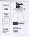
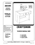
MODEL NO.
113.221611
Serial
Number
Model and serial
number may be found
at the rear of the base,,
You should record both
model and serial number
in a safe place for
future use,
8 INCH DIRECT
TABLE SA W
CAUTION:
READ
ALL
o assembly
INSTRUCTIONS
CAREFULLY
® operating
o repair
Sold
DRIVE
by SEARS,
Part No, SP5022
ROEBUCK
AND
parts
CO,,
Chicago,
IL
60684
U.S.A.
Primed
i_ U S A
FULL ONE YEAR WARRANTY
ON CRAFTSMAN
TABLE SAW
If within one year from the date of purchase, this Craftsman Table Saw fails due to a defect in
material or workmanship, Sears will repair it, free of charge
WARRANTY SERVICE IS AVAILABLE BY RETURNING THE TABLE SAW TO THE NEAREST
SEARS RETAIL/CATALOG
STORE OR SERVICE CENTER/DEPARTMENT
IN THE UNITED
STATES
This warranty gives you specific legal rights and you may also have other rights which vary
from state to state,
SEARS, ROEBUCK
AND CO,,, Scars Tower, BSC 4%3, Chicago, iL 60684
GENERAL SAFETY iNSTRUCTiONS
FOR POWER TOOLS
1. KNOW YOUR POWER TOOL
Read and understand the owner's manual and
labels affixed to the tool Learn its application
and limitations as well as the specific potential
hazards peculiar to this tool
2. GROUND ALL TOOLS
This tool is equipped with an approved 3conductor cord and a 3-prong grounding type
plug to fit the propergrounding
type receptacle,
The green conductor
in the cord is the
grounding wire° Never connect the green wire to
a live terminal
3. KEEP GUARDS IN PLACE
In working order, and in proper adjustment and
alignment.
4. REMOVE ADJUSTING KEYS
AND WRENCHES
Form habit of checking to see that keys and
adjusting
wrenches are removed from tool
before turning it on.
5. KEEP WORK AREA CLEAN
Cluttered areas and benches invite accidents.,
Floor must not be siippery due to wax or
sawdust.
6, AVOID DANGEROUS ENVIRONMENT
Don't use power tools in damp or wet locations
or expose them to rain. Keep work area well
lighted Provide adequate surrounding
work
space..
7, KEEP CHILDREN AWAY
All visitors should be kept a safe distance from
work area,
8. MAKE WORKSHOP CHILD-PROOF
-- with padlocks,
master switches,
or by
removing starter keys.
9. DON'T FORCE TOOL
It wit! do the job better and safer at the rate for
which it was designed
10. USE RIGHT TOOL
Don't force tool or attachment to do a job it was
not designed for.
11. WEAR PROPER APPAREL
Do not wear loose clothing, gloves, neckties
jewelry (rings, wrist watches) to get caught
moving
parts,
Nonslip
footwear
recommended
Wear protective hair covering
contain tong hair Roll long sleeves above
elbow
or
in
is
to
the
12. USE SAFETY GOGGLES (Head Protection)
Wear Safety goggles (must comply with ANSI
Z87.,1) at all times° Everyday eyeglasses only
have impact resistant lenses, they are NOT
safety glasses. Also, use face or dust mask if
cutting operation is dusty, and ear protectors
(plugs or muffs) during extended periods of
operation.
13. SECURE WORK
Use clamps or a vise to hold work when
practical It's safer than using your hand, frees
both hands to operate tool
14. DON'T OVERREACH
Keep proper footing and balance at all times,
15. MAINTAIN TOOLS WITH CARE
Keep tools sharp and clean for best and safest
performance,, Follow instructions for lubricating
and changing accessories,
16. DISCONNECT TOOLS
Before servicing; when changing accessories
such as blades, bits, cutters, etc
17_ AVOID ACCIDENTAL STARTING
Make sure switch is in "OFF" position before
plugging in,
18. USE RECOMMENDED
ACCESSORIES
Consult the owner's manual for recommended
accessories,
Follow
the instructions
that
accompany
the accessories_
The use of
improper accessories may cause hazards.
19. NEVER STAND ON TOOL
Serious injury could occur if the tool istipped or
if the cutting tool is accidentally contacted,
Do not store materials above or near the toot
such that it is necessary to stand on the tool to
reach them
20. CHECK DAMAGED PARTS
Before further use of the tool, a guard or other
part that is damaged should be carefully
checked to ensure that it will operate properly
and perform its intended function., Check for
alignment of moving parts, binding of moving
parts, breakage of parts, mounting, and any
other conditions that may affect its operation. A
guard or other part that is damaged should be
properly repaired or replaced
21. DIRECTION OF FEED
Feed work into a blade or cutter against the
direction of rotation of the blade or cutter only
22. NEVER LEAVE TOOL RUNNING
UNATTENDED
Turn power off Don't leave tool until it comes to
a complete stop,
ADDITIONAL
SAFETY
FOR TABLE
WARNING: FOR YOUR OWN SAFETY, DO NOT
OPERATE YOUR SAW UNTIL IT IS COMPLETELY
ASSEMBLED AND INSTALLED ACCORDING TO
THE INSTRUCTIONS,..
AND UNTIL YOU HAVE
READ AND UNDERSTAND THE FOLLOWING:
1. GENERAL
SAFETY
INSTRUCTIONS
FOR
POWER TOOLS. _. SEE PAGE 2
2, GETTING TO KNOW YOUR SAW.,, SEE PAGE
2O
3. BASIC SAW OPERATION _., SEE PAGE 23
4. MAINTENANCE
._. SEE PAGE 31
5. STABILITY OF SAW
if there is any tendency for the saw to tip over or
move during certain cutting operations such as
cutting extremely
large heavy panels or long
heavy boards, the saw should be bolted down.
If you attach any kind of auxiliary
table
extensions over 24" wide to either end of the saw,
make sure you either bolt the saw to the bench or
floor as appropriate, or support the outer end of
the extension
from the bench or floor, as
appropriate,
6. LOCATION
The saw should be positioned so neither the
operator nor a casual observer is forced to stand
in line with the saw biade,
7. KICKBACKS
A "KICKBACK"
occurs
during
a rip-type
operation when a part or all of the workpiece is
violently thrown back toward the operator
Keep your face and body to one side of the
sawblade, out of line with a possible "Kickback."
Kickbacks -- and possible injury from them -can usually be avoided by:
A Maintaining
the rip fence parallel to the
sawblade,
B Keeping the sawblade
sharp Replace or
sharpen antikickback
pawls when points
become dull
C. Keeping
sawblade
guard,
spreader,
and
antikickback
pawls in place and operating
properly The spreader must be in alignment
with the sawblade and the pawls must stop a
kickback
once it has started. Check their
action before ripping
D, NOT ripping work that is twisted or warped or
does not have a straight edge to guide along
the rip fence
E NOT releasing work until you have pushed it
all the way past the sawblade.
F. Using a push stick for ripping widths of 2 to 6
in., and an auxiliary fence and push block for
ripping widths narrower than 2 in. (See "Basic
Saw Operation
Using The Rip Fence"
section )
G NOT confining the cut-off piece when ripping
or cross-cutting
H When ripping apply the feed force to the
section of the workpiece between the saw
blade and the rip fence.
8. PROTECTION:
EYES, HANDS, FACE, EARS,
BODY
A if any part of your saw is malfunctioning,
has
INSTRUCTIONS
SAWS
been damaged or broken ...such as the motor
switch, or other operating control, a safety
device or the power cord.
cease operating
immediately
until the particular
part is
properly repaired or replaced
B Wear safety goggles that comply with ANSI
Z87.1, and a face shield if operation is dusty.
Wear ear plugs or muffs during extended
periods of operation.
C
Smali loose pieces of wood or other objects
that contact the rear of the revolving blade can
be thrown back at the operator at very high
speed. This can usually be avoided by keeping
the guard and spreader in place for all thrusawing operations (sawing entirely thru the
work) AND by removing all loose pieces from
the table with
a long stick
of wood
IMMEDIATELY after they are cut off
D,
Use extra caution when the guard assembly is
removed for resawing, dadoing, rabbeting, or
molding ,-- replace the guard as soon as that
operation is completed
E
For rip or rip-type cuts, the following end of a
workpiece to which a push stick or push board
is applied must be square (perpendicular
to
the fence) in order that feed pressure applied
to the workpiece by the push stick or block
does not cause the workpiece to come away
from the fence, and possibly cause a kickback
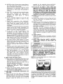
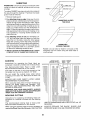
F During rip and rip type cuts, the workpiece
must be held down on the table and against
the fence with a push stick, push block, and/or
featherboards A featherboard is made of solid
lumber per sketch
5/I 6" APA_R T
G NEVER turn the saw "ON" before clearing the
table of all tools, wood scraps, etc, except the
workpiece and related feed or support devices
for the operation planned
H NEVER place your face or body in line with the
cutting tool.
t NEVER pface yourfingers or hands in the path
of the sawblade or other cutting tool
J NEVER reach in back of the cutting tool with
either hand to hold down or support the
workpiece, remove wood scraps, or for any
other reason Avoid awkward operations and
hand positions where a sudden slip could
cause fingers or hand to move into a sawblade
or other cutting tool
K. DO NOT perform layout, assembly, or setup
work on the table while the cutting tool is
rotating
L, DO
NOT
perform
any
operation
"FREEHAND"
-- always use either the rip
fence or the miter gauge to position and guide
the work
M NEVERusetheripfencewhencrosscuttingor
the miter gaugewhenripping,DO NOTuse
the rip fenceasa lengthstop
Neverholdontoortouchthe"freeend"ofthe
workpieceor a "free piece"that is cut off,
while poweris "ON" and/orthe sawbladeis
rotating
N Shut"OFF"thesawanddisconnectthepower
cord when removing the table insert,
changing the cutting tool, removing or
replacing the blade guard, or making
adjustments
O Provide adequatesupport to the rear and
sides of the saw table for wider or tong
workpieces
P. Plastic and composition (like hardboard)
materialsmaybe cut on your saw However,
since these are usually quite hard and
slippery,the antikickbackpawlsmaynot stop
a kickback,
Therefore,beespeciallyattentiveto following
proper set-up and cutting proceduresfor
ripping Donotstand,orpermitanyoneelseto
stand,in linewith a potentialkickback
Q If you stall or jam the sawblade in the
workpiece, turn saw "OFF", remove the
workpiecefrom the sawblade,andcheckto
see if the sawbladeis parallelto the miter
gaugegroovesandif thespreaderis in proper
alignmentwiththesawbladeIf rippingat the
time,checkto seeif the rip fenceis parallel
with the sawbladeReadjustas indicated
R DO NOT remove small pieces of cut-off
materialthat maybecometrappedinsidethe
blade guard while the saw is running This
could endanger your hands or cause a
kickbackTurnsaw"OFF"andwaituntilblade
stops
S. Useextracarewhenrippingwoodthat hasa
twistedgrainor is twistedor bowedi it may
rock on the tableand/orpinchthe sawblade
T Nevergangcrosscutor rip -- lining up more
possible for the operation being performed
Keep all guards in place whenever possible
12_ Do not use any blade or other culling tool
marked for an operating speed less than 3450
RPM. Never use a cutting tool larger in diameter
than the diameter for which the saw was
designed. For greatest safety and efficiency
when ripping, use the maximum diameter blade
for which the saw is designed, since under these
conditions the spreader is nearest the blade.
13. NEVER operate the saw unless the proper insert
is installed
14, NEVER feed material into the cutting tool from
the rear of the saw An accident and serious
injury could result
t5, NEVER use another person as a substitute for a
table extension, or as additional support for a
workpiece that is longer or wider than the basic
saw table, orto assist in feeding or supporting or
pulling the workpiece,
DO NOT pull the workpiece
through the
sawblade -- position your body at the nose (infeed) side of the guard: start and complete the
cut from the same side This will require added
table support for tong or wide workpieces that
extend beyond the length or width of the saw
table
16. THINK SAFETY.
Safety is a combination
of operator common
sense and alertness at att times when the saw is
being used
r
17_ NOTE AND FOLLOW SAFETY INSTRUCTIONS THAT APPEAR ON THE FRONT OF
YOUR SAW.
READ
I
li
WE,AR
U_E
_EEP
U_E
AND
UNDERSTAND
5AFE'T_
GOGGLES
I_AWSLAI_E
GG_gO
OWNERS
MANUAL
5
FOR
1 H P_$_SAWING
_
BEFORE
KNOW
DO
HOW
t_O_
OPERATING
MACH|NE
TO AVOIO'*_ICt_ACKS,*
tJ_.RFORM
OP_RATION_
'F_
EEHAf_I
E=ANGERI o. ou. ow.sAFETY:
HANOS
OUr
A ' PUSH'$T_CK
WARNING:
OF
PATP:
=' WHEN
use
OF
_AWI_t.A_E
I
NI_VE
_
REACH
AAOURL1
On
OV,_ _
_AWgLA
D_
R[QUIR_O
1_0 VOLT
15 A_P
a_NCH
CtRCIJtT
AtG3
USE
I_ AMP
TiME
DELAY
I_GJSE
18. WARNING: DO NOT ALLOW FAMILIARITY
(GAINED FROM FREQUENT USE OF YOUR
SAW) TO BECOME
COMMONPLACE.
ALWAYS REMEMBER THAT A CARELESS
FRACTION OF A SECOND IS SUFFICIENT TO
INFLICT SEVERE INJURY.
than one workpiece in front of the blade
(stacked vertically, or horizontally outward on
the
table)
and
then
pushing
through
sawblade
The blade could pick up one or
more pieces and cause a binding or loss of
control and possible injury
NOTE: Do not overtighten
wrench to just "snug" it
9. KNOW YOUR CUTTING TOOLS
A° Dull, gummy, or improlSerly sharpened or set
cutting tools can cause material to stick, jam,
stall the saw, or kickback at the operator
Minimize potential injury by proper cutting
tool and machine maintenance
NEVER ATTEMPT TO FREE A STALLED
SAWBLADE
WITHOUT
FIRST TURNING
THE SAW OFF.
B- Never use grinding wheels, abrasive cut-off
wheels, friction wheels (metal slitting blades)
wire wheels or buffing wheels
10o USE ONLY ACCESSORIES
DESIGNED FOR
THIS SAW,
11_ Make sure the top of the arbor or cutting tool
rotates toward you when standing in normal
operating position Also make sure the cutting
tool, arbor collars and arbor nut are installed
properly
Keep the cutting tool as low as
WEAR
arbor nut. Use the arbor
YOUR
The operation of any power tool can result in foreign
objects being thrown into the eyes, which can result
in severe eye damage Always wear safety goggles
comptying with ANSI Z87 1 (shown on Package)
before commencing
power too! operation
Safety
Goggles are available at Sears retail or catalog
stores.
4
MOTOR SPEC FICATIONS
AND
ELECTR!CAL
REQUIREMENTS
MOTOR SPECIFICATIONS
The AC motor used in this saw is a non-reversible
type, with the following specifications:
Amperes ......................................
7.8
Hertz ....................................
60
Phase ......................................
Single
RPM ...................................
3450
Rotation (viewed from
Sawblade end) ..........
Counterclockwise
MOTOR SAFETY PROTECTION
1
2
3.
4
5
6
MOTOR SAFETY PROTECTION
REPEATED STALLING OF THE SAW BLADE
WILL SHORTEN THE LIFE OF THE MOTOR.
Always avoid stalling the blade If the motor has
been abused (repeated stalling) and fails to start
(hums), TURN THE SWITCH OFF, ALLOW THE
MOTOR TO COOL, THEN RE-START IT
ALWAYS USE SHARP BLADES A dull blade
requires excessive power and does not produce
quality results
NOTE: The starting
relay is a GRAVITY
SENSITIVE TYPE. NEVER TURN THE POWER
ON WHILE TH E SAW tS UPSIDE DOWN AS THIS
WILL DAMAGE THE MOTOR.
Frequent opening of fuses or circuit breakers
may result if motor is overloaded, or if the motor
circuit is fused with a fuse other than those
recommended
Do not use a fuse of greater
capacity without consulting the power company°
Although the motor is designed for operation on
the voltage and frequency specified on motor
nameplate, normal loads will be handled safely
on voltages not more than 10% above or below
the nameplate voltage
Heavy loads, however, require that voltage at
motor terminals by not tess than the voltage
specified on nameplate
Most motor troubles may be traced to loose or
incorrect
connections,
overloading,
reduced
input voltage (which results when small size wires
are used in the supply circuit) or when the supply
circuit
is extremely
long
Always
check
connection,
load and supply circuit when the
motor fails to perform satisfactorily.
Check wire
sizes and lengths with table at end of this section
CONNECTING
TO POWER SUPPLY OUTLET
If power cord is worn or cut, or damaged in any way,
have it replaced immediately.
WARNING: IF NOT PROPERLY GROUNDED THIS
POWER TOOL CAN CAUSE AN ELECTRICAL SHOCK
PARTICULARY WHEN USED IN DAMP LOCATIONS
CLOSE TO PLUMBING. IF AN ELECTRICAL SHOCK
OCCURSTHEREtSTHEPOTENTIALOFASECONDARY
HAZARD SUCH AS YOUR HANDS CONTACTING
THE SAW BLADE.
If you are not sure that your outlet,
as pictured
below, is properly
grounded,
have it checked
by a
qualified
electrician
Your unit is for use on 110=120volts,
and has a plug
that looks like illustration
below
This power tool is equipped
with a 3-conductor
cord
and grounding
type plug which
has a grounding
prong, approved
by Underwriters'
Laboratories
and
the Canadian Standards Association
The ground
conductor has a green jacket and is attached to the
toot housing at one end and to the ground prong in
the attachment plug at the other end
This plug requires a mating 3-conductor grounded
type outlet as shown
WARNING:
DO NOT PERMIT
FINGERS
TO
TOUCH
THE TERMINALS
OF PLUGS WHEN
INSTALLING
OR REMOVING THE PLUG TO OR
FROM THE OUTLET.
3-PRONG
PLUG
@
GROUNDING
"_
PRONG
PROPERLY GROUNDED
3-PRONG OUTLET
Plug power cord into a 110-120V properly grounded
type outlet protected by a 15-amp dual element
time delay or CircuibSaver fuse or circuit breaker
If the outlet you are planning to use for this power
tool is of the 2 prong type, DO NOT REMOVE OR
ALTER
THE GROUNDING
PRONG
IN ANY
MANNER
Use an adapter as shown below and
always connect
the grounding
lug to known
ground.
A temporary adapter as shown below is available for
connecting plugs to 2-prong receptacles The green
grounding lug extending from the adapter must be
connected to a permanent ground such as to a
properly grounded outlet box
A temporary adapter as illustrated is available for
connecting
plugs to 2-prong
receptacles
The
temporary adapter should be used only until a
properly grounded outlet can be installed by a
qualified electrician
GROUNDING
3-PRONG
PLUG
_"'_-
_
MAKE
_-_
CONNECTED
_-'l(_'_lt
/
LUG
_
SURE THIS tS
TO A
KNOWNGROUND
RECEPTACLE
ADAPTER
WARNING:
THE GREEN
GROUNDING
LUG
EXTENDING
FROM THE ADAPTER MUST BE
CONNECTED
TO A PERMANENT
GROUND
SUCH AS TO A PROPERLY GROUNDED OUTLET
BOX. NOT ALL OUTLET BOXES ARE PROPERLY
GROUNDED.
If you are not sure that your outlet box is properly
grounded, have it checked by a qualified electrician.
NOTE: The adapter illustrated is for use only if you
already
have a properly
grounded
2-prong
rec'eptacte_ Adapter is not allowed in Canada by the
Canadian Electrical Code
The useof anyextensioncordwill causesomeloss
of power.To keepthistoa minimumandtoprevent
over-heatingandmotorburn-out,usethefollowing
tableto determinethe minimumwiresize(A.WoG)
extensioncord.
Useonly3 wireextension¢ordswhichhave3-prong
groundingtypeplugsand3-polereceptacles
which
acceptthe toolsplug.
Extension Cord Length
Wire Size A.W.G.
Up to 100 Ft ..............................
!4
100-200 Ft ..................................
12
200-400 Ft
8
..................
...............
CONTENTS
WARRANTY
.......................................
2
GENERAL SAFETY INSTRUCTIONS
FOR POWER TOOLS
............................
2
ADDITIONAL
FOR TABLE
3
SAFETY INSTRUCTIONS
SAWS ...........................
MOTOR SPECIFICATIONS
AND ELECTRICAL
REQUIREMENTS
............................
5
UNPACKING AND CHECKING CONTENTS
., 6
Tools Needed
...............................
6
List of Loose Parts ...........................
7
ASSEMBLY ..........................................
Installing Handwheels ...........................
Adjusting Blade Insert .......................
Checking Heeling or Parallelism of
Saw Blade to Miter Gauge Groove ............
Adjusting Parallelism of Saw Blade to Miter
Gauge Groove ................................
Adjusting 90 Degree Bevel Stop .............
Adjusting Bevel Pointer ........................
Adjusting 45 Degree Bevel Stop .............
Installing Table Extensions
.................
Aligning Table Extensions ...................
To Raise Extension
......................
To Lower Extension ..............................
Leveling Extensions ........................
To Lower Outer Edge of Extension
........
TO Raise Outer Edge of Extension ..........
Aligning Table Extensions with Front of Table
To Move Outer Edge of Extension Back .....
To Move Outer Edge of Extension Forward ,
Installing Blade Guard
Aligning Spreader
...............................
Attaching Rip Fence ...........................
Aligning Rip Fence .......................
Adjusting Miter Gauge ......................
Mounting Saw to Legs or Bench .............
........................
,,u,u,H
'
9
9
10
11
I2
12
13
13
14
14
14
14
I5
15
15
16
17
18
19
19
t9
20
20
21
21
21
21
21
21
21
22
BASIC SAW OPERATION USING THE
MITER GAUGE ..................................
Work Helpers ................................
Crosscutting
..................................
Repetitive Cutting .............................
Miter Cutting
...............................
Bevel Crosscutting
...............................
Compound Miter Cutting .....................
23
23
24
25
25
26
26
BASIC SAW OPERATION USING THE
RIP FENCE .....................................
Ripping
......................................
Bevel Ripping
.....................................
Ploughing and Molding
......................
Resawing ......................................
Rabbeting
..................................
Dadoing
Molding and Cutting
.........................
Using Featherboards
...........................
26
27
27
29
29
30
30
30
31
MAINTENANCE
...............................
31
.....................................
32
....................................
.....
..................................
LUBRICATION
RECOMMENDED
TROUBLE
ACCESSORIES
SHOOTING
.........................
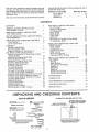
SQUARE
MUST BE TRUE°
STRAIGHT
3t4" THICK.
DRAW
7/16 tn.
#2 Phillips Screwdriver
Combination
35
CONTENTS
COMBINATION
BOARD
LIGHT
ALONG
LINE ON
THIS EDGE
EDGE OF BOARD
THIS EDGE MUST
BE PERFECTLY
_'_
"} ",
STRAIGHT
Long Nose Pliers
SHOULD BE NO GAP OR OVERLAP
HERE WHEN SQUARE IS FLIPPED
OVER tN DOTTED POSITION
Square
Hex "L" Wre_
3/16", t/8", 5/32"
33
33
' ="'111
NEEDED
Medium Screwdriver
.............
REPAIR PARTS ..................................
AND CHECKING
UNPACKING
TOOLS
7
7
8
GETTING TO KNOW YOUR SAW ...........
On-Off Switch .................................
Elevation Handwheel .........................
Tilt Handwheel
..................................
Miter Gauge ................................
Blade Guard ..............................
Table Insert ...................................
Rip Fence
Removing and Installing Saw Blade .........
To Install Saw Blade ...........................
Model 1 ! 3 221611 Table Saw with Table Extensions
is shipped complete in one carton
Separate all parts from packing materials and check
each one with the illustration and the list of Loose
Parts to make certain alf items are accounted for,
before discarding any packing material
If any parts are missing, do not attempt to assemble
the table saw, plug in the power cord or turn the
switch on until the missing parts are obtained and
are installed correctly
F
Apioly a coat of automobile wax to the table.
Wipe att parts thoroughly with a clean, dry cloth.
WARNING: FOR YOUR OWN SAFETY, NEVER
CONNECT PLUG TO POWER SOURCE OUTLET
UNTIL ALL ASSEMBLY STEPS ARE COMPLETE,
AND YOU HAVE READ AND UNDERSTAND THE
SAFETY AND OPERATIONAl, INSTRUCTIONS_
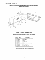
LIST OF LOOSE PARTS
ITEM
DESCRIPTION
A Guard Assembly .......................
B Extension Table LH ......................
C Extension Table R..H...................
D Handwheel ..............................
E Rip Fence Assembly ...................
F Miter Gauge Assembly .................
G Owners Manual ......................
QTY.
1
1
1
2
1
1
1
H
J
K
L
M
N
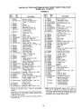
Loose Parts Bag No. 507545
(Containing the following items):
Wrench, Arbor ..........................
Wrench, Shaft ..........................
Support, Spreader .....................
Bracket, Spreader .....................
Clamp, Spreader_.. ..................
Nut, Wing 1/4-20 .......................
1
1
1
1
t
2
O
P
Q
R
S
S
T
U
V
W
Loose Parts Bag No. 507546
(Containing the following items):
Washer, t7/64 x 9/16 x 3/64 ..........
Screw, Pan Hd. 8_32 x 3/8 ............
Nut, Sq.. 1/4-20 ........................
Screw, Soc. Set 1/4-20 x 7/8 .........
Lockwasher, Ext. I/4 ................
Lockwasher, Ext. #8 ......................
Nut, Hex 1/4-20
Screw, Truss Hd 1/4-20 x 5/8 .........
Screw, Flat Hd 1/4-20 x 5/8 ............
Key,Switch ...........................
4
2
2
2
4
2
2
2
14
1
........................
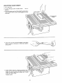
INSTALLING
D
_S
--- o
_R
ASSEMBLY
HANDWHEELS
REMOVE CARDBOARD
FROM
UNDERNEATH
MOTOR
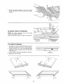
1 From among the loose parts find two #8 external
tockwashers and two 8-32 x 3/8 inch long Phillips
screws
2. Install
elevation
handwheel
onto
elevation
shaft
by lining up FLAT SPOT on shaft with flat inside
handwheel. Install screw and Iockwasher.
3. Install bevel handwheel
onto bevel shaft by
lining up FLAT SPOT on shaft with flat inside
handwheet, Install screw and Iockwasher
LO(
LOCKWASHER
SCREW
WARNING: Failure to complete the following two
steps could result in damage to your saw.
4. Turn elevation handwheel counter-clockwise
to
pull motor away from inner packing cardboard,
5 Remove cardboard.
SCREW
7
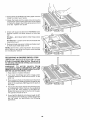
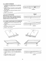
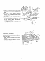
ADJUSTING BLADE INSERT
1 ,, Turn saw over
2, Loosen Phillips screw in blade insert
do not
remove,
3 Remove blade insert by lifting slightlyand pulling
insert toward front of saw to disengage from key
hole slot
BLADE INSERT
HEAD
SCREW
4, Tab at rear of insert should engage in saw table
firmly It may be necessary to bend tab slightly
using pliers.
\
5 Install blade insert by placing keyhole slot in
insert over screw head in saw table and pushing
insert to rear of saw table sliding tab in insert
under saw table ledge
Tighten screw
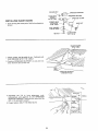
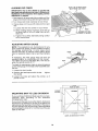
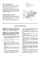
CHECKING
HEELING OR PARALLELISM
OF SAW BLADE TO MITER GAUGE
GROOVE
MARK 'X" ON
TOOTH
While cutting, the material must move in a straight
line PARALLEL to the SAW BLADE
. . therefore
both the miter gauge GROOVE and the RIP FENCE
must be PARALLEL to the SAW BLADE
If the saw blade is not parallel to the miter gauge
groove, it is said to have "HEEL" This condition can
cause the workpiece to bind or move workpiece
away from the rip fence at the end of a cut, possibly
causing a kickback
WARNING:
TO
AVOID
INJURY
FROM
ACCIDENTAL
START MAKE SURE SWITCH IS
"OFF" AND PLUG IS NOT CONNECTED
TO
POWER SOURCE OUTLET.
1. Elevate blade to maximum
elevation handwheef
height
by turning
2. Mark an "X" on one of the teeth which _s SET
(bent) to the LEFT
3, Place the head of a combination square in the
MITER GROOVE. Adjust blade of square so that it
just touches the tip of the MARKED tooth
4. Move squar;_ to REAR, rotate blade to see if
MARKED tooth again touches blade of square.
5 If tooth touches square the same amount
FRONT and REAR, sawblade is PARALLEL
MITER GAUGE GROOVE
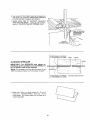
ADJUSTING
BLADE TO
PARALLELISM
MITER
GAUGE
at
to
OF SAW
GROOVE
If tooth
does not touch front and rear the
mechanism underneath must be adjusted to make
the blade PARALLEL to miter gauge groove
1. Loosen the four hex socket screws in the top of
the table next to the saw blade using a 3/16 inch
hex L wrench This will allow the mechanism
below the table to be shifted sideways
\
//
2 Fold a piece of cardboard or heavy paper over the
blade to protect your hands
3 Grasp the blade and the cradle rod and move the
mechani,sm right or left a small amount as needed
to make the square touch the same amount front
and rear Tighten one screw
4 Check with squareto
determine
if MARKED tooth
touches
square
the same amount
at front and
rear
tf it does -- alternately
sfowly
If it does not -- loosen
required
amount
5 Recheck
to make
tighten
screw
other three screws
and move blade
the
blade clearance
to table and table insert
sure blade does not hit
NOTE: Use the hex L wrench as shown Do not usea
pair of pliers or any other tool to gain more leverage
on the setscrew
wrench
ADJUSTING
90 DEGREE
BEVEL STOP
(IMPORTANT: Blade must be square (90 ° ) to table
in order to accurately align the saw° Using care in
the following adjustments will help assure accurate
woodworking cuts.)
WARNING:
TO AVOID
INJURY
FROM
ACCIDENTAL START, TURN SWITCH "OFF" AND
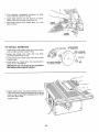
REMOVE PLUG FROM POWER SOURCE OUTLET
BEFORE ADJUSTING BEVEL STOP.
t Raise blade to highest elevation
2 Turn bevel handwheet just until it stops under
moderate pressure Blade should be 90 ° to the
table top
3 Place a square flush on the table top to the left of
the sawblade and slide the square up against the
body of the sawblade, NOT against the teeth of
the blade
4 The square should be nearly flush with the body
of the sawblade When this is so, the sawblade is
said to be 90° with respect to the table top
Notice the bevel pointer on the front of the saw
The pointer should be at 0 °
5, If you feel the blade is not close enough to 90°
with respect to the table top, further adjustment
can be made by performing
the following
operation&.
IO
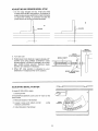
ADJUSTING
90 DEGREE
BEVEL STOP
1 On the stop bracket are two t0-32 pan head
screws which set 90 ° stop position. If condition A
exists the two screws need to be turned clockwise
to obtain 90 ° setting if condition B exists the
stews should be turned counterclockwise
I
[
I.,.,.,,-'_BLADE
t/BLADE
H
IF
II
H
tl
If
BEVEL
HANDWHEEL
l
BEVEL
STOP BRACKET
2.. Turn saw over
BEVEL
SHAFT
X_
3, Rotate bevel crank blade is in approximateFy 40 °
position and using phillips screwdriver
rotate
screws slightly in direction necessary to correct
gap, (rotate screws equally),. Recheck blade
position and readjust if necessary
4, When 90 ° stop position is adjusted to your
satisfaction re-adjust pointer to 0 ° position,
ADJUSTING
BEVEL ADJUSTING
SCREWS
!
BEVEL POINTER
r
If blade IS SQUARE to table:
@
1,, Check pointer.
If POINTER DOES NOT point to the "0" mark on the
bevel scale:
2 Remove Elevation Handwheel
3 Loosen screw and adjust
medium screwdriver
pointer
BEVEL
POINTER
using
@
4o Install Elevation Handwheel
@
11
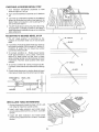
CHECKING
45 DEGREE
BEVEL STOP
1 Turn elevation handwheet
blade as high as it will go
2o Turn bevel handwheel
45 °
clockwise
to raise
t/
clockwise
to tilt blade to
3 Lay head of combination square on the blade of
square as illustrated and place head against the
blade Make sure square is not touching TIP of
one of the saw TEETH
4, The 45° blade stop is set during manufacturing.
If adjustment is needed proceed to next step,, If
bevel adjustment is satisfactory go on to installing
table extensions
ADJUSTING
45 DEGREE
BEVEL
,,
/,
H
t
I
STOP
ANGLE
! The 45 ° blade position is controlled
by the
location of the sheet metal nut on end of bevel
shaft
2, ff condition A exists the sheet metal nut needs to
be turned clockwise (CW) to obtain 45 ° setting If
condition
B exists the nut should be turned
counterclockwise
(CCW),
A
\\
\\
\\
\\
3 To correct condition A - Rotate bevel handle
CCW approximately
2 turns, place 11/16 inch
wrench on sheet metal nut and hold in place
while rotating handle counterclockwise
in small
increments
Recheck blade position after each
rotation.
/"
\\
/
\
4. To correct condition B - Same procedure as No
3, except, rotate handle clockwise while holding
nut,
ANGLE
5, Check blade clearance by rotating blade by hand
making sure blade does not strike insert or table
\x
\\
\\
SHEET
METAL
BEVEL
WASHER
_X
LINK
BEVEL
SHAFT
FLAT HEAD
HEX SOCKET
SCREWS
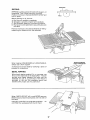
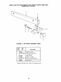
INSTALLING
TABLE
EXTENSIONS
1, Among toose parts locate fourteen 1/4-20 x 5/8
inch tong flat head hex socket screws
2 Install right table extension and install seven
screws using a 5/32 inch hex L wrench. Just start
screws
3 Install left table extension and install seven
screws using a5/32 inch hex Lwrench Just start
screws
12
3 Install left table extension and install seven
screws using 5/32 inch hex L wrench Just start
screws
ALIGNING
TABLE
EXTENSIONS
NOTE; The table extensions
must be the same
height as the table and level,
Place combination square on table and extension,
"-_
TO
RAISE
BE SAME HEIGHT
EXTENSION
SHOULD
AS TABLE
EXTENSION
1, If extension is low loosen three screws on top of
the table extension A, B, and C See illustration
L==J
2, Tighten screws D, E, F, and G underneath table
extension to raise extension even with table top
front and rear
I"
l
3, Check height with square and tighten A, Band C
4, Repeat for left extension
EXTENS{ON
13
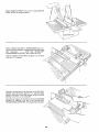
TO LOWER
EXTENSION
!. If extension is too high loosen four screws on
underside of the extension D, E, F, and G. See
illustration.
2 Tighten screws A, B and C on top of table
extension to lower extension even with table top
front and rear.
EXTENSfON
3. Check height with square and tighten screws D,
E, F and G
4. Repeat for left extension.
,,,u,
LEVELING
Place combination
that end of blade
HoLd square firmly
between extension
TO LOWER
SHOULD BE
NO GAP
EXTENSIONS
square on table and extension so
extends over edge of extension.
on saw table and check for gap
and blade of square.
OUTER
EDGE OF EXTENSION
1. Loosen screws B_ E, and Fon right extension. See
ilhJstration
2 Tighten screws C, D, and G until table extension
is Level
3o Snug down screws B, E, and Fr.
EXTENSION
4 Repeat for left extension
TO RAISE
OUTER
EDGE
OF EXTENSION
1 Loosen screws C, D, and G on right extension.
2. Tighten screws B, E, and F until table extension is
tevet
1
3. Snug down screws C, D, and G
4. Repeat for left table extension.
EXTENSION
14
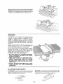
ALIGNING
TABLE
FRONT
OF TABLE
EXTENSIONS
!, Place blade of combination
table and table extension,,
2, Extension
should
square
WITH
on front of
line up with table,
'l'l='l'_'l'_'l'l'l'_'t'l'l'I'l'J'l,t'l'l'l'l't'l,l't,t
TO MOVE OUTER
EDGE
EXTENSION
BACK
OF
1 Loosen screws C and F in right extension
illustration
2, Tighten
up,
I' I
screws B and G until extension
See
is lined
3 Snug down screws C and F
4, Recheck level and flatness to table
5, Check left extension
6. Adjust left extension
in same manner
F
TO MOVE
EXTENSION
OUTER
EDGE
FORWARD
OF
1 Loosen screws B and G in right extension
lltI! l
2, Tighten screws C and F until extension is lined
up
3, Snug down screws B and G
4 Recheck level and flatness to table Check left
extension,
4_ Recheck level and flatness to table
, LH
5 Check left extension
6 Adjust left extension
in same manner
|S
G
SQUARE
NUT
_....._
TRUSS HEAD
SCREW
5/8 IN LONG
INSTALLING
BLADE
,
_..,_F
St'IPPORT
_
SPREADER BRACKET
_ _
J"
"_,_(7"_ K-_}_-"_'_.,.,_
SPREADER CLAMP
1
GUARD
SOCKET
HEAD
1. From among the loose parts, find the hardware as
shown
SPREADER
_
SETSCREW
_
_,_-_,_1_
g
718
,.,
Lo.a
FLAT WASHER/_)
/
"-_ (J'--
I
"IL_&j
WING NUT
/
@'_.
HEX NUT -"-'_'_
LOCKWASHER
EXT, 1/4 IN.
BLADE SQUARE
WITH TABLE
2 MAKE SURE THE BLADE IS ALL THE WAY UP
AND SQUARE WITH THE TABLE
3, Position SPREADER SUPPORT on rod until it is
even with the end of the rod
SPREADER SUPPORT
EVEN WITH ROD
4. Assemble the 7/8 in, long setscrews,
nuts,
Iockwashers
and washers to the SPREADER
SUPPORT BRACKET and slip the nuts into the
slot in the spreader support
5 Finger tighten ONLY THE HEX NUTS
16
6 Laya pieceof flat straightwoodandasquareon
sawtableandrotatethe SPREADER
SUPPORT
until the bracketis alignedwith square
7 MAKE SURE END OF SUPPORT,BRACKET
ANDRODAREEVEN.,+usingan1/8in+HexL
wrench,TIGHTENTHESETSCREWSONLY,
ENDS OF SUPPORT
AND BRACKET TO
BE EVEN WITH
END OF ROD
TIGHTEN
SETSCREW ONLY
SPACE EQUAL TO APPROX
3 THICKNESSES
OF PAPER
....
ALIGNING
KERF
:_
WOOD
o/
J
SPREADER
IMPORTANT:
The SPREADER must always be
PARALLEL to the sawblade and in the MIDDLE of
the cut (KERF) made by the sawblade.
NOTE: The spreader is thinner than the width of the
KERF by approximately
six thicknesses of paper
/
SPREADER
SPACE
EQUAL
3 THICKNESSES
1 Make two folds in a small piece (6 x 6 in,,) of
ordinary
NEWSPAPER
making
three
thicknesses
The folded paper witl be used as a
"spacing gauge"
17
TOAPPROX,
OF PAPER
LOOKING
DOWN
ON
SAW
PIECE OF
STRAIGHT WOOD
2, Installthe SPREADER
CLAMP.Placespreader
between spreaderclamp and bracket, Move
forwarduntilallthreeareinline,TIGHTENWING
NUTS.
3 Lay a piece of straight flat wood againstthe
sawblade.Insertfoldedpaperbetweenspreader
andstrip of wood.
4,MAKESURETHE HEXNUTS UNDERNEATH
ARELOOSE
5 Lift the antikickbackpawlto clearthewoodand
holdthe spreadertightlyagainstthewood,Make THREE THICKNESSES
OFPAPER
sure the wood is against the saw blade
WING NUT
TIGHTENTHEHEXNUTS,
This will alignthe spreaderin the middleof the
cut (KERF)madeby sawblade
ATTACHING
"IGHTLY
AGAINST
HOLD WOOD
BLADE
1
ACK
HOLD SPREADER
TIGHTLY AGAINST
WOOD
BRACKET
SPREADER
CLAMP
RIP FENCE
Apply a coat of paste wax to the top surface and
front ledge of the saw table This will allow the fence
to slide more easily
1 Loosen fence
clockwise,.
lock
knob
by turning
counter-
2. Attach fence head by placing head of fence over
front ledge in saw table.,
FENCE LOCK
KNOB
18
ALIGNING
MUST
LINE UP WITH
SLOT FRONT
AND
RiP FENCE
MITER
REAR
IMPORTANT: The rip fence MUST be parallel with
saw blade and miter grooves in order to help prevent
KICKBACK of the workpiece when ripping. Careful
adjustment is required,
1.. Hold head of rip fence and slide on table until the
edge of the fence lines up with the right miter slot.
2 Turn fence lock knob clockwise to lock fence.
3 If..fence does not line up with miter slot front and
rear:
A. Loosen the two hex screws in top of fence
HEAD
B. While holding head of rip fence, move rear of
rip fence right or left until edge lines up with
miter s!ot_
C Tighten hex screws alternately
not to move fence
ADJUSTING
MITER
LOOSEN TWO HEX
SCREWS TO ADJUST
being careful
GAUGE
NOTE: The graduations are manufactured to very
close tolerances which provide suitable accuracy
for average woodworking.
In some cases where
extreme accuracy is required, when making angle
cuts, for example, make a trial cut and then recheck
it.
HEAD
If necessary, the miter gauge head can then be
swiveled slightly to compensate and then locked
The HEAD should be SQUARE (90 ° ) with the bar
when the pointer points to "0".
To check for squareness, place an accurate square
on the mitergauge
If the head is NOTSQUAREwith
the bar:
BAR
1. Loosen the lock handle.
2 Position the head square with the bar .. •tighten
the handle
3 Loosen the screw and adjust the pointer,
points to zero
so it
12-3/4
REAR OF SAW
4 HOLES
.312 DIA'
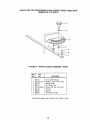
MOUNTING
SAW
TO
LEGS
OR
OPENING
BENCH
If you purchase Craftsman Steel Legs for your saw,
assemble
them
according
to the directions
furnished with them
If you mount the saw on any other bench, makesure
that there is an opening in the top of the bench the
same size as the opening in the bottom of the saw so
that the sawdust can drop through, Recommended
working height is 33 to 37 in. from the fop of the saw
table to the floor°
11-3/16
NOTE; All dimensions
19
in Inches,
GETTING
TO KNOW YOUR
5 BLADE
SPREADER
SAW
GUARD
6 TABLE
INSERT
\
8 SAW BLADE
TABLE
4
"k*
RIP FENCE
EXTENSION
MITER
GUAGE
T
TABLE
EXTENSION
MITER GUAGE
LOCK KNOB
3 TILT
RIP FENCE
LOCK KNOB
HANDWHEEL
,BEVEL SCALE
BEVEL POINTER
2 ELEVATION
POWER
CORD
1 ON-OFF
HANDWHEEL
SWITCH
1. ON-OFF SWITCH
CAUTION: Before turning switch on, make sure
the blade guard is correctly installed and
operating properly,
The On-Off Switch has a locking feature. THiS
FEATURE IS INTENDED TO HELP PREVENT
UNAUTHORIZED
AND POSSIBLE HAZARDOUS
USE BY CHILDREN AND OTHERS
f
INSERT
KEY
A Insert Key into switch
B TO turn saw ON
stand to either side of the
blade never in line with it. insert finger under
switch lever and pull END of lever out
TURN
ON
After turning switch ON, always allow the
blade to come up to fuff speed before cutting
Do not cycle the motor switch on and off
rapidly, as this may cause the sawblade to
loosen In the event this should ever occur,
allow the sawblade to come to a complete stop
and retighten the arbor nut normally, not
excessively. Never leave the saw while the
power is "ON"
C TO turn saw OFF
PUSH lever in Never
leave the saw until the cutting toot has come to
a complete stop
TURN
O\F_F
_,
_ \_-=_,_
REMOVE
KEY
"OFF",
WHEN
SAW IS NOT
IN USE o , .
REMOVE
KEY AND KEEP IT IN A SAFE
PLACE . , . ALSO , , . IN THE EVENT OF A
POWER
FAILURE
(ALL OF YOUR LIGHTS
GO OUT) TURN SWITCH
OFF,.
, LOCK IT
AND
REMOVE
THE
KEY.
THIS
WILL
PREVENT
THE SAW FROM STARTING
UP
AGAIN
WHEN THE POWER COMES
BACK
ON.
D To lock switch in OFF position
hold switch
IN with one hand
REMOVE key with other
hand
WARNING:
FOR YOUR
OWN SAFETY,
LOWER BLADE OR OTHER CUTTING TOOL
BELOW TABLE SURFACE. (IF BLADE IS
TILTED, RETURN IT TO VERTICAL (90 ° )
POSITION). ALWAYS LOCK THE SWITCH
2O
2. ELEVATION HANDWHEEL
,elevates orlowers
the blade, Turn counterclockwise
to elevate
clockwise to lower
D, Lift insert from front end, and pull toward front
of saw
NEVER OPERATE THE SAW WITHOUT THE
PROPER INSERT IN PLACE. USE THE SAW
BLADE INSERT WHEN SAWING
. . USE THE
MOLDING INSERT WHEN MOLDING
3. TILT HANDWHEEL
tilts the blade for bevel
cutting Turn counterclockwise
to tift toward left
, clockwise to tilt toward right
When the blade is tilted to the LEFT as far as it witt
go, it should be at 45 ° to the table and the bevel
pointer should point 45 °
NOTE: There are LIMIT STOPS inside the saw
which prevent the blade from tilting beyond 45 °
to the LEFT and 90 ° to the RIGHT
(See
"Adjustments"
section "Blade Tilt, or Squareness
of Blade to Table")
,
RIP FENCE,
is locked in place by tightening the
lock knob To move the fence, loosen the knob
and grasp the fence with one hand at the front
Holes are provided in the rip fence for attaching a
wood facing when using the dado head, or
molding head
Select a piece of smooth straight wood approx
3/4" thick, at least as long as the rip fence, and at
Ieast 7-1/2" wide (high) to permit clamping of
featherboards
4. MITER GAUGE
head is locked in position for
crosscutting
or mitering by tightening the lock
knob ALWAYS LOCK IT SECURELY WHEN IN
USE
Attach it to the fence with two Round Head #10
Wood Screws 2 in long To remove the facing,
loosen the screws, slide the facing forward and
puli the screws through the round holes
5. BLADEGUARD
must always be in place and
working properly for all thru-sawing cuts That is,
all cuts whereby
the blade cuts completely
through the workpiece
WOOD
To remove the guard for special operation,
loosen both wing nuts, slide spreader back and
up. DO NOT DISTURB THE SETTING OF THE
SPREADER SUPPORT BRACKET
When replacing
the guard, insert spreader
between bracket and clamp and slide forward
TIGHTEN BOTH WINGNUTS SECURELY
6. TABLE INSERT is removable for removing
installing blades or other cutting tools
\
# 10 WOOD SCREWS
CAUTION: When positioning fence for maximum
rip, make sure end of fence HEAD is even with edge
of table extension. Fence cannot be locked securely
beyond the edge of the table extension.
B Raise blade guard
REMOVING
SAWBLADE
AND
\
or"
WARNING: FOR YOUR OWN SAFETY, TURN
SWITCH "OFF" AND REMOVE PLUG FROM
POWER
SOURCE
OUTLET
BEFORE
REMOVING INSERT.
A Lower the blade below the table surface
C Loosen Screw
FACING
\
(Do Not Remove)
INSTALLING
WARNING:
TO
AVOID
INJURY
FROM
ACCIDENTAL
START, TURN SWITCH "OFF" AND
REMOVE
PLUG FROM POWER SOURCE OUTLET
BEFORE
REMOVING
OR
INSTALLING
SAWBLADE.
BLADE
INSERT
PHILLIPS
HEAD
SCREW
NOTE: When installing the blade
make sure the
upper saw teeth are pointing toward the front of the
saw,
and that the blade and collars are clean, and
free from any burrs
The HOLLOW side of the collars must be against the
blade.
NOTE: Always place the LARGE collar on the shaft
before the blade
NOTE: Do not overtighten
wrench to just "snug" it
I
arbor nut Use the arbor
1 Loosen Phillips head screw in blade insert
not remove
Do
2 Remove blade insert by lifting stightly and pulling
insert to disengage from key hole slot
21
3, Turn elevation handwheel clockwise to raise
motor shaft as high as it will go,
4, Insert shaft wrench over flat portions of motor
spacer and arbor wrench over arbor nut
5 Hold shaft wrench and loosen arbor nut with
arbor wrench
ARBOR
WRENCH
t
TO
INSTALL
SAWBLADE
FLAT SURFACES
1 Install large inner blade collar onto motor shaft
with rounded surface toward motor,,
2 Install saw blade onto shaft with top teeth
pointing toward front of saw
3 Install sina!! outer blade collar with flat surface
toward blade
4, Install arbor nut Note: Arbor nut should just be
snug Do not overtighten
IMPORTANT: Do not attempt to run saw without
both blade collars properly installed_
SMALL COLLAR
(1-3/4" DIAMETER)
HEX NUT
TOP TEETH POINTING
TO FRONT OF SAW
5, Install blade insert by placing keyhole slot in
insert over screw head in saw table and pushing
insert to rear of saw table engaging tab in insert
onto saw table Iedge
Tighten
LARGE COLLAR
(2" DIAMETER)
screw.
22
BASIC SAW OPERATION
USING
THE
MITER
CROSSCUTTING,
MITER
CUTTING,
BEVEL
CUTTING,
COMPOUND
MITER CUTTING
and
when RABBETING across the end of a narrow
workpiece, the MITER GAUGE is used
by the back of the blade and thrown toward the
operator), Stand to either side of the blade
Keep your hands clear of the blade and out Of
the path of the blade,
7,
WARNING: FOR YOUR OWN SAFETY, ALWAYS
OBSERVE
THE
FOLLOWING
SAFETY
PRECAUTIONS
IN ADDITION TO THE SAFETY
INSTRUCTIONS
ON PAGES 2, 3, and 4.
8.
If blade stalls or stops while cutting, TURN
SWITCH OFF before attempting
to free the
blade,,
9. Do not reach over or behind the blade to pul! the
workpiece through the cut,. oto support long or
heavy workpieces, ,. to remove cut-off pieces of
material or FOR ANY OTHER REASON
1 Never make these cuts freehand (without using
the miter gauge or other auxiliary devices)
because the blade could bind in the cut and
cause a KICKBACK or cause your fingers or
hand to slip into the blade,
2., Always lock the miter gauge securely
GAUGE
10, Do not pick up small pieces of cut-off material
from the table. REMOVE them by pushing them
OFF the table with a long stick, Otherwise they
could be thrown back at you by the rear of the
blade.
when in
USe.
3. Remove rip fence from table,
4, Make sure blade guard is installed for atl "thrusawing"
operations
(when sawbiade
cuts
entirely thru the thickness of the workpiece,)
Replace guard IMMEDIATELY after completion
of dadoing, molding or rabbeting cuts.,
5. Have blade extend approximately
1/8 in above
top of workpiece° Additional
blade exposure
would increase the hazard potential,
11. Do not remove small pieces of cut-off material
that may become TRAPPED inside the blade
guard while the saw in RUNNING THIS COULD
ENDANGER
YOUR
HANDS
or cause
a
K1CKBACK_
Turn the saw OFF. After the blade has stopped
turning, lift the guard and remove the piece.
12 If workpiece is warped, place the CONCAVE
side DOWN This will prevent it from rocking
while it is being cut,
6, Do not stand directly in front of the blade in case
of a THROWBACK
(Small cut-off piece caught
SLIGHTLY LESS THAN
THICKNESS OF WORKPIECE
UP TO
WORK
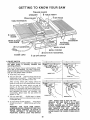
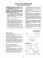
HELPERS
t-5/8
Before cutting any wood on your saw, study all of
the "Basic Saw Operations'L
Notice that in order to make some of the cuts, it is
necessary to use certain devices "Work Helpers"
like the Push Stick, the Push Block and the Auxiliary
Fence, which you can make yourself
15
After you have made a few practice cuts, make up
these "helpers" before starting any projects, Make
the "Push Stick" first, To rip the piece for the push
stick, start out with a wide board, say 11-t/2 in. wide
and set the rip fence 9-3/4 in. from the blade
45 ° NOTCH
NOTE: All dimensions
in inches
PUSH STICK
THESE EDGES MUST
BE PARALLEL
3/4
PLYWOOD
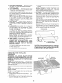
PUSH STICK AND PUSH BLOCK
Make the Push Stick using a piece of 1 x 2.
Make the Push Block using a piece of 3/8 in and 3/4
in. plywood
_\
The small piece of wood 3/8 in, x 3/8 in, x 2-1/2 in.
should be GLUED to the plywood ... • DO NOT USE
NAILS, This is to prevent dulling the sawblade in the
event you mistakingly cut into the push block,
1"4"3/4_
114 -"
2-1/2
Position the handle in the center of the plywood and
fasten together with glue and woodscrews
3/8
NOTE:
23
All dimensions
in inches
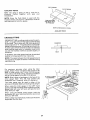
3/8 PLYWOOD
3/8 PLYWOOD
3/'4 PLYWOOD
AUXILIARYFENCE
Make one using a piece of 3/8 in,. and 3/4 in,
plywood
Fasten
together
with
glue
and
woodscrews
NOTE: Since the Push Block is used with the
Auxiliary Fence, the 4-3/4 in dimensions must be
held identical on both the pieces.
THIS FACE AND
THIS EDGE MUST
BE PARALLEL
14
NOTE: All dimensions
AUXILIARY
in Inches
FENCE
CROSSCUTTING
CROSSCUTTING
is cutting wood across the grain,
at 90 _ , or square with both the edge and the flat side
of the wood This is done with the miter gauge and
blade angle set at "0". The graduations on the miter
gauge provide accuracy for average woodworking
In some cases where extreme accuracy is required,
when making angle cuts, for example, make a trial
cut and then recheck it with an accurate square, or
protractor.
WORKPIECE
1 ,
TABLE
_f necessary, the miter gauge head can be swiveled
slightly to compensate for any inaccuracy
NOTE: The space between the miter gauge bar and
the groove in the table is held to a minimum during
manufacturing.
For maximum
accuracy
when using the miter
gauge, always "favor" one side of the groove in the
table In other words, don't move the miter gauge
from side to side while cutting, but keep one side of
the bar riding against one side of the groove
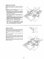
SANDPAPER
PLYWOOD CLAMPED
TO SAWHORSE
NOTE: Glue a piece of sandpaper to the face of the
miter gauge head, This will hetp prevent the
workpiece from "creeping" while it is being cut.
The miter gauge may be used in either of the
grooves in the table. Make sure locking knob is tight.
When using the miter gauge in the LEFT hand
groove, hold the workpiece firmly against the miter
gauge head with your left hand, and grip the lock
knob with your right
LINE FOR CLARITY
When using the RIGHT hand groove, hold the
workpiece with your right hand and the tock knob
with your left hand.
When cutting tong workpieces,
supported from the floor..
make sure the end is
24
REPETITIVE
CUTTING
REPETITIVE CUTTING
is cutting a quantity of
pieces the same length without having to mark each
piece
NOTE: When making repetitive cuts from a long
workpiece make sure it is supported
1 NEVER USE THE RIP FENCE AS A LENGTH
STOP BECAUSE THE CUTOFF PIECE COULD
BIND BETWEEN THE FENCE AND THE BLADE
CAUSING A KICKBACK
2, When making repetitive cuts shorter than 6 in,
clamp a block of wood 3 in long to the table to act
as a length stop
CAUTION: When clamping the block, make sure
that the end of the block is well in front of the
sawblade, Be sure it is clamped securely.
3. Slide the workpiece along the miter gauge until it
touches the block,,
hold it securely
4 Make the cut , pull the workpiece back _ push
the cut off piece off the table with a long push
stick .. DO NOT ATTEMPT TO PICK IT UP AS
THIS COULD ENDANGER YOUR HANDS
MITER
CUTTING
TABLE
MITER CUTTING is cutting wood at an angle other
than 90 ° with the edge of the wood Follow the same
procedure as you would for crosscutting
Adjust the miter gauge to the desired angle, and
lock it
The miter gauge may be used in either
grooves in the table
TOP VIEW
of the
When using the miter gauge in the LEFT hand
groove, hold the workpiece firmly against the miter
gauge head with your left hand, and grip the lock
knob with your right
When using the RIGHT hand groove, hold the
workpiece with your right hand and the lock knob
with your left hand
25
WORKPIECE
BEVEL
CROSSCUTTING
?
BEVEL CROSSCUTTING
is the same as crosscutting except that the wood is cut at an angle
other than 90 ° with the flat side of the wood.
,1
TA!LE
Adjust the blade to the desired angle
Use the Miter Gauge in the groove to the RIGHTof
the blade It cannot be used in the groove to the
LEFT because the blade guard will interfere Hold
the workpiece with your right hand and the Dock
knob with your left hand
COMPOUND
MITER
CUTTING
COMPOUND MITER CUTTING is a combination of
miter cutting and bevel crosscutting
The cut is
made at an angle other than 90 ° to both the edge
and the flat side of the wood
Adjust the miter gauge and the blade to the desired
angle.
Make sure miter gauge is locked
USING
THE
RIP FENCE
RIPPING,
BEVEL RIPPING,
RESAWING
AND
RABBETING are performed using the RiP FENCE
together
with the AUXILIARY
FENCE/WORK
SUPPORT, PUSH STICK OR PUSH BLOCK..
5 Have blade extend approximately
1/8 in above
top of workpiece
Additional
blade exposure
would increase the hazard potential
WARNING: FOR YOUR OWN SAFETY, ALWAYS
OBSERVE
THE
FOLLOWING
SAFETY
PRECAUTIONS
IN ADDITION TO THE SAFETY
INSTRUCTIONS
ON PAGES 2, 3 and 4.
7 Keep your hands clear of the blade and out of
the path of the blade,,
6 Do not stand directly in front of the blade in case
of a KICKBACK
Stand to either side of the
blade
8 If the blade stalls or stops while cutting, TURN
SWITCH OFF before attempting
to free the
blade
1 Never make these cuts FREEHAND (without
using the rip fence or auxiliary devices when
required) because the blade could bind in the
cut and cause a KICKBACK
2. Always lock the rip fence securely
,r
when in use
3. Remove miter gauge from table.
Do not reach over or behind the blade to pull the
workpiece through the cut.,
to support long or
heavy workpieces
, to remove small cut-off
pieces
of material
or FOR ANY OTHER
REASONS
10, Do not pick up small pieces of cut-off material
from the table. REMOVE them by pushing them
OFF the table with a long stick Otherwise they
could be thrown back at you by the rear of the
blade
4 Make sure blade guard is installed for aft thrusawing
type
cuts.
Replace
the guard
IMMEDIATELY
following
completion
of
resawing,
rabbeting,
dadoing,
or molding
operations
11 Do not remove small pieces of cut-off material
that may become TRAPPED inside the blade
guard while the saw is RUNNING, THIS COULD
ENDANGER
YOUR
HANDS
or cause a
KICKBACK,
Frequently
check
the action
of the
ANTtKICKBACK
PAWLS by passing
the
workpiece alongside of the spreader while saw
is OFF
Turn the saw OFF After the blade has stopped
turning, lift the guard and remove the piece,
Pull the workpiece TOWARD you. If the PAWLS
do not DtG into the workpiece and HOLD it..
the
pawls
must
be
REPLACED
OR
SHARPENED
See "Maintenance"
section
12, If workpiece is warped, place the CONCAVE
side DOWN, This will help prevent it from
rocking while it is being ripped.
26
WORKPIECE
RIPPING
RIPPING is cutting a piece of wood with the grain, or
lengthwise. This is done using the rip fence,
Position the fence to the desired WIDTH OF RIP and
lock in place
TABLE
k.j
Before starting to rip, be sure
A, Rip Fence is parallel to sawblade.
B Spreader is properly aligned with sawbfade
C. Anti-Kickback
pawls are functioning
properly,
D Rip fence knob is tightened to secure the fence to
the table
Position the fence to the desired WIDTH OF RIP by
measuring the distance from the sawblade
ALWAYS SUPPORT
LONG WORKPIECES
When ripping LONG BOARDS or LARGE PANELS,
always t,_sea work support.
A simple one can be made by clamping
plywood to a sawhorse.
BEVEL
a piece of
RIPPING
When bevel ripping material 6 in or narrower, use
fence on the right side of the blade ONLY. This will
provide more space between the fence and the
sawblade for use of a push stick if the fence is
mounted
to the left, the sawbtade guard may
interfere with proper use of a push stick
When "WIDTH OF RIP" is 6 in and WIDER use your
RIGHT hand to feed the workpiece until it is c_ear of
the table,
Use LEFT hand ONLY to guide the workpiece.
not PUSH the workpiece with the left hand
Ldo
27
When "WIDTH OF RIP" is 2 in, to 6 in, wide USE THE
PUSH STICK to feed the work,
When "WIDTH OF RIP" is NARROWER than 2 in,,
the push stick CANNOT be used because the guard
will
interfere
USE the AUXILIARY
FENCEIWORK SUPI_ORT and PUSH BLOCK
Attach Auxiliary Fence/Work
with two "C" clamps
Support
to rip fence
Feed the workpiece by hand along the AUXILIARY
FENCE until the end is approx, 1 in past the front
edge of the table Continue to feed using the PUSH
BLOCK until the cut is complete.,
Hold the workpiece in position and instalf the PUSH
BLOCK by sliding it on top of the AUXILIARY
FENCE/WORK SUPPORT (This May Raise Guard)
\
\\
28
FLE
Narrow strips thicker than the Auxiliary Fence/Work
Support may enter the guard and strike the baffle
CAREFULLY raise guard only enough to clear the
workpiece. Use PUSH BLOCK to complete cut.
RESAWING
RESAWlNG is a "thru-sawing"
cut made by ripping
a piece of wood through its thickness
Do not
attempt to res'aw BOWED or WARPED material
NOTE: To RESAW a piece of wood it will be
necessary to remove the blade guard _, and use the
AUXILIARY FENCE/WORK SUPPORT. (See "Work
Helpers").
Clamp it to the table so that the workpiece will
SLIDE EASILY but not TILT or MOVE SIDEWAYS
without BINDING between the two fences.
Do not clamp directly to the bottom edge of the table
because the "swivel" of the clamp will not grip
properly Place a small block of wood between the
bottom edge of the table and the "C" clamp.
WARNING: FOR YOUR OWN SAFETY . . :
1. DO NOT "BACK UP" (REVERSE FEEDING)
WHILE RESAWING
BECAUSE THIS COULD
CAUSE A KICKBACK.
2, MAKE FIRST PASS TO A DEPTH SLIGHTLY
LESS THAN ONE-HALF THE WIDTH OF THE
BOARD;
KEEP SAME FACE
OF BOARD
AGAINST FENCE FOR SECOND PASS AS THE
FIRST PASS,
SMALL BLOCK
OF WOOD
3. INSTALL BLADE GUARD IMMEDIATELY UPON
COMPLETION
OF THE
RESAWING
OPERATION,
PLOUGHING
AND MOLDING
MOLDING is shaping the workpiece with the grain
the long way of the workpiece, using the fence. Use
featherboards and push sticks as required
PLOUGHING
is grooving with the grain the long
way of the workpiece, using the fence. USE featherboards and push sticks as required
PLOUGHING
MOLDING
29
RABBETING
RABBETING is known as cutting out a section of the
corner of a piece of material, across an end or along
an edge
FIRST
CUT
RABB!
To make a RABBET requires cuts which do not go all
the way through the material Therefore the blade
guard must be removed
1 Remove blade guard
2 For rabbeting along an edge (long way of workpiece) as shown, add facing to rip fence approximately as high as the workpiece is wide Adjust
rip fence and blade to required dimensions; then
make first cut with board flat on table as any rip
(type) cut; make second cut with workpiece on
edge Foitow all precautions, safety instructions,
and operational instructions as for ripping, or rip
type operations, including feather boards and
push stick, etc
RABBETING ALONG
THEEDGE
3 For rabbeting across an end, for workpiece 101/2" and narrower make the rabbet cut with the
board flat on the table Using the miter gauge
fitted with a facing, follow the same procedures
and instructions for cross cutting making successive cuts across the width of the workpiece to
obtain the desired width of cut DO NOT use the
rip fence for rabbeting across the end
4, INSTALL BLADE GUARD IMMEDIATELY UPON
COMPLETION OF RABBETING OPERATION
RABBETING
ACROSS THE END
Rabbet cuts can also be made in one pass of the
workpiece over the cutter using the dado head or
molding head
DADOING
LARGE BLADE
COLLAR (2" DIA,)
Instructions
for operating
the Dado Head are
contained in booklet furnished with the Dado Head
DADO
HEAD
ARBOR
NUT
li
The Recommended
Dado Head is listed under
Recommended Accessories in this manual
The arbor on the saw, is only long enough so that
the widest cut that can be made is 1/2" wide
Do not install the outside loose collar before
screwing on the arbor nut Make sure the arbor nut
is tight
ALWAYS USE DADO INSERT LISTED UNDER
RECOMMENDED
ACCESSORIES
When using the dado head it will be necessary to
remove the Blade Guard and Spreader
USE
CAUTION,
USE FEATHERBOARDS
AND PUSH
STICKS AS REQUIRED
WARNING'. FOR YOUR OWN SAFETY, ALWAYS
REPLACE THE BLADE, GUARD AND SPREADER
WHEN YOU ARE FINISHED DADOING_
MOLDING
CUTTING
Instructions
for operating the Molding Head are
contained in a booklet furnished with the Molding
Head
The recommended
molding head is listed under
Recommended Accessories in this manual
USE FEATHERBOARDS
REQUIRED
When using the molding head it will be necessary to
remove the Blade Guard and Spreader. USE CAUTION
ALWAYS
REPLACE
THE BLADE
GUARD
AND
SPREADER WHEN YOU ARE FINISHED MOLDING
30
AND PUSH STICKS, etc AS
-C'CLAMPS
WORK
USING
SUPPORT
FEATHERBOARD
"C'*CLAMPS
FEATHERBOARDS
Featherboards are not employed during non thrusawing operations when using the miter gauge
Use featherboards
for all other non "thru-sawing"
operations
(when
sawblade
guard
must
be
removed) Featherboards are used to keep the work
in contact with the fence and table as shown, and to
stop kickbacks,,
Add 8 inch high fiat facing board to the fence, the
full length of the fence
Mount featherboards to fence and table as shown,
so that leading edges of featherboards will support
workpiece until cut is complete, and the workpiece
has been pushed completely
past the cutter
(sawbtade, dado head, molding head, etc ) with a
pushstick, as in ripping,
Before starting the operation
cutter befow table surface):
(switch
"OFF"
and
(a) install featherboards
so they exert pressure
on the workpiece; be positive they are secure,
and
(b) Make sure by trial that the featherboards
stop a kickback if one should occur
will
Replace the sawblade guard as soon as the non
thru-sawing
operation is complete,
MAmNTENANCE
WARNING:
TO
AVOID
INJURY
FROM
ACCIDENTAL START, TURN SWITCH "OFF" AND
REMOVE PLUG FROM POWER SOURCE OUTLET
BEFORE MAINTAINING
OR LUBRICATING YOUR
SAW.
Do not allow sawdust to accumulate
inside the saw
Frequently blow out any dust that may accumulate
inside the saw cabinet and the motor
Frequently clean your cutting
Gum and Pitch Remover
tools with Craftsman
A coat of automobile-type
v,,=x applied to the table
will hetp to keep the surface clean and allow
workpieces to slide more freely, Treat unplated and
unpainted steel parts and surfaces with Sears "Stop
Rust,"
If the power cord is worn or cut, or damaged in any
way, have it replaced immedia[efy
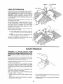
Make sure the teeth of the ANTtKICKBACK
are always sharp To sharpen:
t Identify
guard
the dull tooth
or teeth
pawls
Remove blade
3 Hold spreader with left hand and place pawl over
corner or workbench
2, Rotate pawl toward rear of spreader so that teeth
are above top of spreader
4 Sharpen the dull tooth using a few light strokes of
a fine-cut file
31
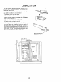
LUBRiCATiON
The saw motor bearings have been packed at the
factory
with proper
lubricant
and require no
additional lubrication,
The following
parts should be oiled occasionally
with SAE Noo 20 or No, 30 engine oil
1_ Elevation guide slot and pivot
2, Elevation screw threads,
3., Bevel screw threads (First clean with Craftsman
Gum & Pitch Remover.)
4 Bevel and elevation
link pivot points
5 Cradle pivot pin bearing points
6, Bearing points in miter gauge and rip fence
The saw table and other major parts are made of
aluminum and require no special care. A coat of
automobile-type
wax applied to the table will help to
keep the surface clean and allow workpieces to slide
more freely, Treat unplated and unpainted steel
parts and surfaces with Sears "Stop Rust "
BEARING
SCREW
ELEVATION
POINTS
.7
I
ELEVATION
LINK
ELEVATIOI'
, GUIDE SLOT
AND PIVOT tl
IN CRADLE
32
tl
I
LD
I
RECOMMENDED
ITEM
Saw Blades .........................
*Molding Head Set ......................
Dado Insert ............................
Molding Insert ...........................
Taper Jig .................................
Dado Set ...............................
ACCESSORIES
ITEM
Steel Legs ...............................
Retractable Caster Set ....................
CAT. NO,
See Catalog
9-3222
9-22281
9-22282
9-3233
9-32581
CAT. NO.
9-22236
9-22221
9-22222
"Power Tool Know How Handbook"
Table Saw .............................
9-2918
*Smaller Diameter Molding Heads cannot be used
because they do not provide adequate depth of
cut
The above recommended accessories are current
and were available at the time this manual was
printed
TROUBLE
SHOOTING
WARNING:
TO
AVOID
INJURY
FROM
ACCIDENTAL START, TURN SWITCH "OFF" AND
ALWAYS REMOVE PLUG FROM POWER SOURCE
OUTLET BEFORE TROUBLE SHOOTING.
TROUBLE
TROUBLE
Excessive
SHOOTING
PROBABLE
vibration,
t
Blade
out
1 Miter gauge
properly
Cuts binds, burns or
stalls motor when
ripping_
1 Dull
blade
tooth
CAUSE
REMEDY
of balance
Cannot make square cut
when crosscutting_
-- GENERAL
not
with
1 Discard
Blade
1 See section
adjusted
improper
1 Sharpen
2 Warped
2 Make
board
3
Rip fence
to blade
not
parallel
4
Spreader
out of
alignment
not true
at 90 °
or 45 ° positions,
1 Stop
nuts
1 Sawdust
Excessive
1. Blade
and
blade
oversize
unsmooth
wobble°
kerr
cut)
Gauge"
or replace
blade
sure
not properly
screw
concave
feed
on threads
of tilt
side
section,
*Aligning
4 See "Assembly"
Blade Guard "
section.
"Installing
t
section,
_Blade
See 'Assembly"
"Squareness
or elevating
or hollow
t
is facing
slowly
3 See "Assembly"
adjusted
Tilt crank and elevating
crank turn hard.
(Causes
'Miter
blade
set
'down"
Cut
and use a different
of Blade
See "Maintenance
and
Rip
Tilt,
1 Replace
Lubrication"
collars
2 Make sure
is between
blade
wobble
2 Blade
not installed
properly
before
33
the _arge collar (2" Dia )
motor
and blade
(Installed
blade)
or
to Table"
screw
has excessive
Fence"
section
TROUBLE
SHOOTING
-- MOTOR
NOTE: Motors used on wood-working
tools are
particulary
susceptible
to the accumulation
of
sawdust and wood chips and should be blown out or
'*vaccummed"
frequently to prevent interferences
with normal motor ventilation
NOTE: The starting relay is a GRAVITY SENSITIVE
TYPE NEVER TURN THE POWER ON WHILE THE
SAW IS UPSIDE DOWN AS THIS WILL DAMAGE
THE MOTOR
TROUBLE
PROBABLE
Excessive noise°
REMEDY
CAUSE
t Have motor
1 Motor
checked
technician
your
Motor fails to develop
lull power,. (Power
output of motor decreases
rapidly with decrease in
voltage at motor terminals
For example, a reduction
of 10% in voltage causes
a reduction of 19% in
maximum power output of
which the motor is capable,
white a reduction of 20%
in voltage causes
reduction of 36% in
maximum power output )
1 Circuit
overloaded
with
lights, appliances
other motors
2 Undersize
too
Do
wires
nearest
or circuit
Sears
circuit
Increase
wire
3 Generat
overloading
sizes,
demand
systems
4 Incorrect
1 Low
and
2 Starting
1 Motor
fuses
4 install
or circuit
in power
length
and
of wiring
Electrical
section
from the power
not
relay
trip
not operating
fuses
or circuit
breakers
due
Request a voltage check from the power
company
2 Have retay replaced,
1 Do not cut so fast-Feed work slower into blade
2 Clean out sawdust to provide normal air
circulation through motor
See "Maintenance
and Lubrication"
section
cooling
(Air
restricted
motor
correct
tine
overloaded
Improper
circulation
through
or reduce
the
relay
2
on
distribution
voltage-will
Motor overheats,
or motors
the saw
)
breakers
Motor starts slowly or
fails to come up to
lull speed.
at
for electrical
power may exceed
capacity
of existing
generating
using
Request a voltage check
company
of power
company
facilities
(In
some sections
of the
country,
appliances
Specification
Requirements"
service
is available
store
when
See "Motor
long
by qualified
service
not use other
same
and
Repair
to
sawdust,
accumulating
inside of saw
Burned
Starting relay in motor
will not operate (Motor
does not come up
to full speed°)
Motor
stalls (resulting
in blown
circuit
fuses
or tripped
breakers)
relay contacts
to extended
caused
hold-in
by low
line
Have reiay
(due
from
periods
replaced
the power
and request
a voltage
check
company
voltage
etc )
2 Saw not in upright
position,
3. Loose or broken connections
2 Place saw in upright position
3 Have wiring checked and repaired
I
I Have relay replaced
2 Request a voltage check from the power
company
Starting
relay not operating
2 Voltage
too low to permit
motor to reach operating
3
speed
Fuses
do not
or circuit
have
breakers
3
Install
proper
size
fuses
or circuit
breakers
sufficient
capacity
Frequent opening of
fuses or circuit breakers.
1 Motor
overloaded
2 Fuses
or circuit
do not
capacity
3 Starting
have
1 Don't
2 lnstalt
breakers
cut
so fast-Feed
proper
size
sufficient
relay
(motor
does
normal
speed)
not operating
not
reach
34
3 Have
relay
replaced
fuses
work
slower
or circuit
into
blade
breakers
REPAIR PARTS
PARTS
LIST FOR CRAFTSMAN
8 INCH DIRECT
MODEL NO. 113.221611
DRIVE TABLE
i
8
\
FIGURE
Always
1 - GUARD
ASSEMBLY
Order by Part Number
62935
- Not by Key Number
M
Part
Key
1
2
3
4
5
6
7
8
62916
62911
62519
i62921
iSTD551025
i62561
i62902
i455734
Description
Link, Guard
Guard
Spring, Pawl
Pin
*Washer, 17/64 x 1/2 x 1/32
Pawl
Blade, Spreader
Pin, Roll 1/8 x 3/4
i
*Standard Hardware Item - May be Purchased Locally
35
SAW
PARTS
LiST FOR CRAFTSMAN
8 lINCH DIRECT
MODEL NO. 113.221611
8
DRIVE TABLE
10
9
SAW
1t
12
I
13
68
.i
24
J
\
\ 65
/
/
f,,,t
¢P,
\
64
55
50
51
52
47
42
41-41.40
46
45
63
t5
PARTS LIST FOR CRAFTSMAN
8 INCH DIRECT
MODEL NO. 113.221611
FIGURE
(ey
No.
Part
No.
Key
No.
Description
Part
No.
Description
,=,
t
2
62905
ST D601 'I03
3
4
5
6
7
62436
62625
816075
62908
805297_9
8
]05297-1
9
_293l
10 62915
11 iSTD600805
12 62909
13 62937
14 62924
15 STD601105
22
23
24
SAW
2
H,=
16
17
18
t9
20
2'1
DRIVE TABLE
62936
62442
60256
803709
67085
STD510603
62913
62925
62938
25
26
27
28
29
30
31
62935
62642
STD54!025
62809
STD551225
STD541625
]0074
32
33
34
35
36
}TD551012
STD54t025
62643
60314
_420417
37
ITD611005
38
39
40
816072
816073
STD551037
4I 60240
42 62912
43 STD551208
44 STD510803
45
}2901
46 814638
47 STD522506
48 STD551125
49 816071
50 806752W
Bracket, Cradle
*Screw, Hex Washer Hd
Type "T" 10-32 x 3/8
Nut
Hanger
Rod, Cradle
Extension, Table LH
Screw, Socket Fiat Hd
1/4-20 x 5/8
Screw, Flat Hd
5/16-18 x 1-1/4
Table
Insert, Table
*Screw, Pan Hd 8-32 x 1/2
Extension, Table R.H
Fence Assy, Rip (See Fig 3)
Plate, Switch
*Screw, Pan Hd. Cross
Recess Type "T" 10-32 x 1/2
Lead Assembly
Switch, Locking
Key, Locking
Connector, Wire
Cord with Plug
*Screw, Pan Rec..
Type "T" 6-32 x 3/8
Housing, Switch
oRelay
Gauge Assembly, Miter
(See Fig. 4)
Guard Assembly (See Fig 1)
Support, Spreader
*Nut, Square 1/4-20
Bracket, Spreader
*Lockwasher, External 1/4-20
*Nut, Wing 1/4-20
Screw, Socket Set
1/4-20 x 7/8
*Washer, 17/64 x 9/16 x 3/64
*Nut, Hex 1/4-20
Clamp, Spreader
Screw, Truss Hd. 1/4-20 x 5/8
Screw, Washer Type "T"
1/4-20 x 5/8
*Screw, Pan Rec Type "AB"
No 10 x 1/2
Panel, Front
indicator, Bevel
*Washer, 380 x 47/64 x 1/16
51 60540
52 62919
53 62917
54 62923
55 816076
56 9414920
57 160388
58 814663
59 65093
60 62900
6t 60548
#
62
63
62989
6054I
64
65
66
67
68
60546
60545
18992
60547
6362
69
70
71
72
73
74
75
76
77
78
79
62498
62992
62856
STD541025
60539
62922
STD551025
814770
3540
63062
STD551210
507545
507546
SP5022
t_Nut, Push 3/8
Handwheel, 3-5/8
*Lockwasher, No 8
*Screw, Pan 8-32 x 3/8
Base
Plate, Thrust
*Screw, Hex 1/4-20 x 5/8
*Lockwasher, 1/4
Bracket Lead Screw
Screw, Pan Hd Type "T"
10-32 x 1-1/8
Ring, Retaining 11/16
Nut, Elevation
Link
Pin, Guide
Shaft, Tilt
Washer, t7/64 x 5/8 x 1/16
Nut, Self-Threading
Shaft, Elevation
Clip, Wire
Baffle
Screw, Hex Washer Type "T"
1/4-20 x 3/8
Bracket, Lead Screw
Screw, Hex Locking
1/4-20 x 3/4
Washer, Spring
Washer, Nylon
1:Blade, 8"
Collar, Outer
Nut, Saw Arbor
Collar, Inner
Cradle
oMotor
*Nut, Hex 1/4-20
Ring, Retaining 1/4
Pin, Guide
*Washer, 17/64 x 1/2 x 1/32
Link
Wrench, Arbor
Wrench, Shaft
*Lockwasher Ext, #10
Bag of Loose Parts
(Not Illustrated)
Bag of Loose Parts
(Not Illustrated)
Owners Manual
(Not Illustrated)
QRelay must accompany
motor when motor is
returned for service. Any attempt to repair this
motor may create a hazard unless repair is done by
a qualified service technician
Repair service is
available at your nearest Sears Store.
*Standard
Hardware item - May be purchased
locally.
1"Stock Item- May be secured through the Hardware
Department
of most Sears Retail Stores and
Catalog Order House,
"klf this part is removed, discard and replace with a
new Push Nut
37
PARTS
LIST FOR CRAFTSMAN
8 INCH DIRECT
MODEL NO. 113,221611
7
DRIVE TABLE
6
/
5
FIGURE
3 - RIP FENCE
ASSEMBLY
62937
m,
Key
No.
Pa rt
No,
1 62906
2 STD522505
3
4
5
6
7
62985
62482
STD541231
60543
62939
Description
Channel, Fence
*Screw, Hex Hd, Sems
1/4-20 x 1/2
Head, Fence
Knob, t-1/4 Dia
*Nut, Hex ,Jam 5/16-18
Screw, Truss Hd 5/16-!8
Clip, Shoe
x2
*Standard Hardware Item - May be Purchased Locally
38
SAW
PARTS
LIST FOR CRAFTSMAN
8 INCH DIRECT
MODEL NO. 113.221611
DRIVE TABLE SAW
7
FIGURE
4 - MITER
Key
No.
1
2
3
4
5
6
7
8
GAUGE
Part
No.
62176
STD551010
62173
62175
STD510803
38724
60544
62927
*Standard
ASSEMBLY
62938
Description
Knob, Miter Gauge
*Washer, I3/64 x 5/8 x 1/32
Gauge, Miter
Pin, Miter Pivot
*Screw, Pan Hd 8-32 x 3/8
Pointer
Spacer
Rod, Miter Gauge
Hardware Item = May be Purchased
39
Locally
8 iNCH DIRECT
TABLE SAW
SERVICE
MODEL NO.
113.221611
DRIVE
Now that you have purchased
your
saw should a need ever exist for
simply contact
any Sears Service
Roebuck
and Co stores
Be sure
facts when you call or visit.
8 inch direct drive table
repair parts or service,
Center and most Sears,
to provide all pertinent
The model number of your 8 inch direct drive table saw will
be found on a plate attached to your saw, at the rear of the
base
SAW WITH
TABLE EXTENSIONS
HOW TO ORDER
REPAIR PARTS
WHEN ORDERING
REPAIR
FOLLOWING
INFORMATION:
PART
NUMBER
MODEL NUMBER
113o221611
PARTS,
PART
ALWAYS
GIVE
THE
DESCRIPTION
NAME OF ITEM
8 INCH DIRECT
TABLE SAW
DRIVE
All parts listed may be ordered from any Sears Service
Center and most Sears stores, If the parts you need are
not stocked locally, your order will be electronically
transmitted
to a Sears Repair Parts Distribution
Center
for handling.
Sold
by SEARS,
Part No SP5022
ROEBUCK
AND
CO.,
Form No.. SP5022-2
Chicago,
IL. 60684
U.S.A.
Printed in US.A. 7/87