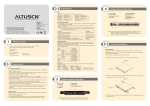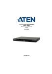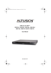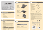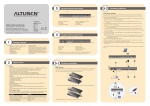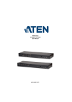
1
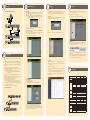
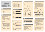
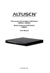
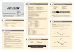
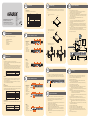
2-2
5-1
Requirements
The KM0032/KM0532/KM0932 can be mounted in a 19" (1U) rack. The mounting brackets can
screw into either the front or the back of the unit so that it can attach to the front or the back of the
rack.
Operating Systems
Supported operating systems are shown in the table, below:
Windows
KM0032/KM0532/KM0932 0/5/9 Console 32-Port
Matrix KVM Switch Quick Start Guide
Technical Phone Support
International:
• 886-2-8692-6959
China:
• 86-10-5255-0110
Japan:
• 81-3-5615-5811
Korea:
• 82-2-467-6789
North America:
• 1-888-999-ATEN Ext: 4988
United Kingdom:
• 44-8-4481-58923
®
© Copyright 2012 ATEN International Co., Ltd. www.aten.com
Altusen and the Altusen logo are trademarks of ATEN International Co., Ltd.
All rights reserved. All other trademarks are the property of their respective owners.
This product is RoHS compliant
1
Linux
Online Registration
International:
• http://support.aten.com
North America:
• http://www.aten-usa.com/product_registration
PAPE-1215-200G Printing Date: 06/2012
UNIX
Novell
Mac
OS
Version
2000 and higher
7.1 and higher
Core 2 and higher
9.0 and higher
9.0 and higher
4.3 and higher
4.2 and higher
Solaris 8 and higher
5.0 and higher
OS 9 and higher
RedHat
Fedora
SuSE
Mandriva (Mandrake)
AIX
FreeBSD
Sun
Netware
3
The KM0032 / KM0532 / KM0932 package consists of:
Phillips head hex
M3 x 6
Phillips head hex
M3 x 6
Phillips head hex
M3 x 8
Single Level Installation
3. Connect the KVM adapter cable to the computer.
Using a KVM adapter cable that is appropriate for the computer you are installing, plug the
adapter cable’s connectors into their respective ports on the computer
4. Connect the KVM adapter cable to the KM0532 / KM0932.
Use Cat 5e/6 cable to connect the KVM adapter cable to any available KVM port on the KM0532
/ KM0932. (Repeat steps 3 and 4 for all computers that you wish to connect. Up to 32 computers
may be connected in this fashion.)
5. Plug a cable from the LAN or WAN into the KM0532 or KM0932's LAN port.
6. Connect a PON unit (Optional)
Use Cat 5e/6 cable to connect the KM0532 or KM0932's PON port to an SA0142 Adapter.
Connect the Adapter to the PON IN port of a PN0108 Power Over the Net™ unit.
7. Ground the switch.
Use the grounding wire supplied with this package to ground the unit by connecting one end of
the wire to the grounding terminal, and the other end of the wire to a suitable grounded object.
Note: Do not omit this step. Proper grounding helps to prevent damage to the unit from surges or
static electricity.
8. Plug the power cords supplied with this package into the KM0532 /KM0932’s Power Socket, and
then into an AC power source. Turn on the power to the KM0532 / KM0932.
9. Connect the console module’s power adapter to the console module and to an AC power source.
10. Turn on the power to the computers.
Hardware Review (Front View)
1
1 KM0032, KM0532, or KM0932
2 Power Cords
1 Daisy Chain Cable (KM0032 only)
1 Mounting Kit
1 Foot Pad Set (4 pcs.)
1 User Instructions
1
Phillips head hex
M3 x 8
4
3
2
KA7230/KA7240
Console Module
KM0532/KM0932
1. Power LED
KM0532
2. KVM Port LEDs
3. Console (User) Port LEDs
4. LAN LED
5. Reset Switch
6. Cover Latch
7. Firmware Upgrade
Recovery Switch
8. Console (User) Port
6
5
1
7
3. Slide the unit into the front or rear of
the rack and secure it to the rack.
8
2
2
4
3
6
5
7
The following hardware components are required for each KVM console:
• A VGA, SVGA, or multisync monitor capable of displaying the highest resolution provided by any
computer on the installation
• Keyboard and mouse (PS/2 or USB)
• Console modules are required to connect KVM consoles to the KM0532 /KM0932. They provide
flexibility for your installation by allowing PS/2 and USB interfaces to be mixed and matched at
the KVM console side. The console modules currently available are listed in the table below.
Contact your dealer for details or refer to the documentation included with your console module.
PS/2-USB Console Module
Virtual Media PS/2-USB Console Module
1
3
2
KM0032
5
4
6
5-2
KA7240
Cables
KVM Adapter Cables
KVM adapter cables connect multiplatform computers (PS/2, USB, Sun, Mac, and serial) and certain
cascaded KVM switches to the KM0032 / KM0532 / KM0932. The KVM adapter cables currently
available are listed in the table below. Contact your dealer for details.
Function
For PS/2 computers
For Sun legacy computers
For serial devices
For USB computers (including Sun and Mac)
For USB computers – Virtual Media and Audio
support
1. Power LED
2. Port LEDs
3. Station ID LED
4. Reset Switch
5. Cover Latch
6. Firmware Upgrade
Recovery Switch
Model Number
KA7120, KA9120,
KA7130, KA9130
KA7140, KA9140
KA7170, KA9170
4
To prevent damage to your installation it is important that all devices are properly grounded.
Use a grounding wire to ground the KM0032 / KM0532 / KM0932 by connecting one end of the
wire to the switch’s grounding terminal, and the other end of the wire to a suitable grounded object.
Hardware Review (Rear View)
1
2
3
7
8
2
3
4
5
KM0532/KM0932
1. Power Sockets
2. Power Switches
3. PON Port
4. Console Ports
5. KVM Ports
6. Grounding Terminal
7. CHAIN OUT Port
8. LAN Port
KM0532
6
1
4
5
KM0932
KA7176
6
7
Other cables that are used to connect up the KM0032 / KM0532 / KM0932 installation include the
following:
Type
Cat 5 Ethernet cable
LIN5-68H1-H11G (45 cm)
KM0032
1. Power Sockets
2. Power Switches
3. KVM Ports
4. Daisy Chain Ports
5. LAN Port
6. Grounding Terminal
1
2
3
KM0032
4
5
5-3
Single Level Installation
In a single level installation, there are no additional KVM switches cascaded or daisy chained
down from the first level KVM switch. To set up a single level installation, refer to the diagram
(the numbers in the diagrams correspond to the numbered steps) and do the following:
8
Connecting Cables
Function
Connecting Console Modules or KVM
Adapter Cable to the switch
Daisy Chaining switches
Grounding
KA7230
The following hardware components are required for each computer that connects to the switch:
• A VGA, SVGA, or multisync video graphics card with an HDB-15 port; or, for legacy Sun
systems, a Sun 13W3 video port
• PS/2 mouse and keyboard ports (6-pin Mini-DIN), or at least one USB port; or, for legacy Sun
systems, a Sun style keyboard port (8-pin Mini-DIN)
5
8
KM0032
Model Number
Computers
4
8
7
Console
Adapter Cable
3
PN0108
Requirements
Function
4
9
6
KM0932
2-1
1. Remove the two screws at the front or
the rear.
2. Screw the two mounting brackets into
the sides of the unit at the front or the
rear.
Package Contents
5-3
Rack Mounting
6
1. Connect the KVM console.
Plug your keyboard, mouse, and monitor into their respective ports on the console module. Each
console port is marked with an identifying icon
2. Connect the console module to the KM0532 / KM0932.
Use Cat 5e/6 cable to connect the LINE IN 1 or LINE IN 2 port of the console module to one of
the Console (User) ports on the KM0532 / KM0932's rear panel.
(Repeat steps 1 and 2 for all KVM consoles that you wish to connect. Up to 5 (KM0532), or 9
(KM0932) KVM consoles may be connected in this fashion (1 port on the front panel, plus 4 or
8 ports on the rear panel).
Note: The distance between any console module and any KVM adapter cable must not exceed
300 m (1000').
5-4
Cascading
KM0532 and KM0932 switches support a 3 level cascade for KM0532 / KM0932 units. They
support a 1 level cascade for other compatible model KVM switches. In other words, slave
switches cannot be cascaded from non-KM0532 / KM0932 switches
Cascading KM0532 / KM0932 Switches
Note: The firmware version of all cascaded KM0532 / KM0932s should match the firmware
version of the first level KM0532 / KM0932.
To cascade KM0532 / KM0932 switches refer to the installation diagram and do the following:
1. Connect the KVM console to the console module.
2. Connect the console module to the KM0532 / KM0932.
Note: The distance between any console module and any KVM adapter cable, or between the
first level and final level KVM switch, may not exceed 300 m (1000').
3. Use Cat 5e/6 cable to connect any KVM port on the parent switch to any of the Console ports on
the child switch.
Note: 1. The number of KVM consoles connected to the first level switch that can
simultaneously access the cascaded switch is limited by the number of Console port
connections between the parent and child switches.
2. The distance between any console module and any KVM adapter cable must not exceed
300 m (1000').
4. Repeat step 3 for each second level KVM switch that you wish to cascade.
5. Follow the instructions given for single level installation to connect computers, power cords,
etc..
Note: It is not necessary to connect cascaded switches to the network. Remote (over the
network) administration of cascaded switches are managed through the of the first level
switch.
6. To cascade third level KVM switches, follow the instructions in steps 3, 4, and 5 when cascading
them from the second level KVM switches.
7. Power on the first level KM0532 / KM0932.
8. Wait one minute, and then power on each second level KM0532 /KM0932.
9. Wait one minute, and then power on each third level KM0532 / KM0932.
10. Plug the power adapters supplied with the console modules into an appropriate AC power
source, and then plug the power adapter cables into the power jacks on the rear of the console
modules.
11. Turn on the power to all the computers.
5-4
6
Cascading
Administrator Setup
First Time Setup
Cascaded KM0532 / KM0932 Installation Diagram
Once the KM0032 / KM0532 / KM0932 installation has been cabled up, the Super Administrator
needs to set the system up for user operation. The most convenient way to do this for the first
time is from one of the consoles.
Note: For remote methods of setting up the network, see IP Address Determination. After the
console has been connected up, and the KM0032 / KM0532 / KM0932 turned on, a login
prompt appears on the console monitor:
KA7230/KA7240
Console Module
7
Logging In
The KM0532 / KM0932 switch can be accessed from a local console or an internet browser.
Browser access is provided for convenience in performing administrative tasks from a remote
location. Port switching and port operation procedures can only be performed from a console
Console Login
When a console is connected to a powered on KM0532 / KM0932 and there is no user logged in,
the KM0532 / KM0932 login screen appears on the display
8
Operation
After you have successful logged in into the Matrix KVM Switch, you can access the server
connected to a port by doing the following:
1. Double clicking on the port’s icon in the Sidebar tree.
Or
2. Selecting the port in the Sidebar tree and clicking Connect in the main panel.
1
2
KM0932
After the console has been connected up, and the KM0032 / KM0532 / KM0932 turned on, a
login prompt appears on the console monitor:
3
KA7230/KA7240
Console Module
Since this is the first time you are logging in, key in the default Username: ADMINISTRATOR;
and the default Password: password.
Note: For security purposes, you should change the password (Port Access � Preferences). The
default Administrator user name can not be changed.
1
Simply key in your Username and Password, then click Login to bring up the Console GUI.
2
After you successfully log in, the Console’s GUI appears:
KM0932
6
Port Operation
The UI provides a toolbar to help you control the KM0032 / KM0532 / KM0932 from within the
captured port. To bring up the toolbar, tap the Toolbar Hotkey (Scroll Lock), twice. The toolbar
appears at the upper left corner of the screen.
KM0932
5-5
• Information about the functions that the Toolbar items perform appears when you move the
mouse over them.
• When the toolbar displays, mouse input is confined to the toolbar area and keyboard input has no
effect on the computer connected to the port. To carry out operations on the computer, close the
toolbar by clicking the X on it; or, recall the UI and select the port again.
Daisy Chaining
Up to 7 KM0032 Expansion KVM Switches can be daisy chained from the first level KM0532 /
KM0932.
First select the User Management tab, then click Add at the bottom of the main panel.
Browser Login
The KM0932 is capable of supporting nine independent KVM consoles, while the KM0532 is
capable of supporting 5 independent KVM consoles. In a complete daisy chained installation, the
KVM consoles that belong to the KM0532 / KM0932 can access and control all of the computers
on the installation.
To set up a daisy chained installation, refer to the diagram and do the following:
1. Use a daisy chain cable set to connect the CHAIN OUT port of the parent KM0532 / KM0932
to the CHAIN IN port of the first KM0032.
Note: 1. The maximum distance between any two switches cannot exceed 10 m.
2. The maximum distance between the KM0532 / KM0932 and the last KM0032 in the
chain cannot exceed 50 m.
2. Follow the instructions given for single level installation to connect computers, LAN, power
cords, etc.
3. For any other KM0032 switches you want to add to the chain, use a daisy chain to connect the
Chain Out port of the parent switch to the Chain In port of the child switch.
4. Power on the installation according to the following procedure:
a) Power on the first level (KM0532 or KM0932) switch.
b) Power on each switch in the chain in turn (second station, then third station, etc.). In each
case, wait for the station position to be ascertained and displayed on the Station ID LED
before powering on the next station. (The Station ID for the first KM0032 is 01, the Station
ID for the second level KM0032 is 02, etc.)
c) After all the KVM switches are powered on, power on the computers.
The KM0032 / KM0532 / KM0932 can be accessed via an Internet browser from any platform
Note: This can be used for remote configuration purposes. Port access can only be performed
from a Console login.
To access the switch, do the following:
1. Open the browser and specify the IP address of the switch you want to access in the browser's
location bar.
2. When a Security Alert dialog box appears, accept the certificate – it can be trusted. If other alerts
appear, accept them as well. Once you accept the certificate(s), the login page appears.
3. Provide your username and password (set by the administrator), then click Login to bring up the
Browser UI Main Page.
Network Configuration
To set up the network, do the following:
1. Click the Device Management tab.
2. Select Network on the menu bar. A screen similar to the one below appears:
9
Specifications
Function
Direct
Max
Console Connections
Port Selection
Console Port
KVM Port
Computer
Connections
Daisy chain
Connectors
Daisy chained Installation Diagram
Switches
LEDs
I/P Rating
Power Consumption
KM0932
KM0032
KM0032
Emulation
Scan Interval
Video
• For dynamic IP address assignment, select Obtain an IP address automatically.
• To specify a fixed IP address, select Set IP address manually, and fill in the IP address.
• For automatic DNS Server address assignment, select Obtain DNS Server address automatically.
• To specify the DNS Server address manually, select Use the following DNS Server, and fill in
the addresses for the Primary and Alternate DNS servers.
LAN
PON
Power
Reset
Power
F/W Upgrade
Console Port (On Line)
KVM Port (On Line /
Selected)
Power
Keyboard/Mouse
Operating Temp.
Storage Temp.
Humidity
Housing
Physical Properties Weight
Dimensions (L x W x H)
Environment
KM0032
KM0532
KM0932
32
8,000
5
9
Via Daisy Chain
OSD, Hotkeys
5 x RJ-45 Female 9 x RJ-45 Female
32 x RJ-45 Female
1 x HPDB-50
Female (Black)
-
-
1 x VHDCI 68 Female (Black)
1 x RJ-45 Female
1 x RJ-45 Female (Black)
1 x 3-prong AC Socket
1 x Semi-recessed Pushbutton
1 x Rocker
1 x Slide
5 (Green)
9 (Green)
32 Dual-colored (Green / Red)
1 (Blue)
100–240V AC, 50/60 Hz; 1A
120V/50W;
240V/51W
120V/45W;
240V/46W
120V/50W;
240V/51W
PS/2; USB; Serial
1–240 Seconds
1280x1024@60Hz max. 300m; DDC2B
0–50˚C
-20–60˚C
0–80% RH, Non-condensing
Metal
6.06 kg
6.07 kg
6.08 kg
43.36 x 41.09 x 4.40 cm