1
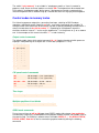
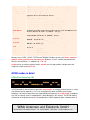
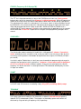
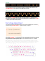
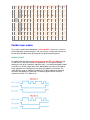
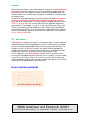
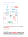
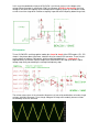
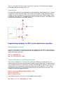
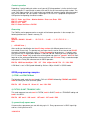
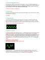
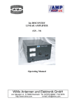
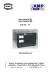
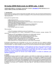
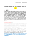
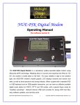
WiMo Antennen und Elektronik GmbH
Am Gäxwald 14, D-76863 Herxheim, Tel. (07276) 96680, FAX: 6978, e-mail: [email protected]
CWKtiny
Instruction manual
V. 2.70
The CWKtiny is a self-contained microprocessor unit with built-in AT keyboard interface, usable as
morse type writer in connection with a standard PC keyboard. It's independend from a PC, easy
to operate and suitable for portable activities. Features known from electronic paddle keyers as
well as CW practising programs are part of the software. Furthermore the CWKtiny is applicable as
a control unit for beacons and repeaters or as a QRSS keyer.
Available characters
To simplify operating the second keyboard level (SHIFT) is not used. Thus, the key "?" had to be
transferred to a position in the first keyboard level. I've arbitrarily chosen the key right from the "L"
(US ENGLISH layout).
numbers:
letters:
punctuation marks:
internet symbols
0-9
A-Z
comma, full point, hyphen, stroke, question mark
@ (the new Morse signal "at")
Keys without any function show no effect, i.e. the error signal described below is not generated.
CW speed
Use Left / Right Arrow Keys to adjust coarsely, and Up / Down Arrow Keys to fine tune
telegraphy speed. While coarse adjustment the letter "v" is transmitted. Left / Right Arrow Keys
even take effect when CW transmission is already in progress. The "ENTER" key toggles
between speed1 and speed2. When speed2 is active the "Caps Lock LED" lights. At the
moment you change over from one to the other speed the currently active one is saved first in
RAM. For storing the new settings permanently press "F10" before you switch off the device.
PTT control / SPACE key / aborting CW transmission
"DEL" keys the PTT line constantly. Pressing DEL a second time returns to the state before.
Typing SPACE bar inserts an additional pause between words, except in some QRSS modes.
"TAB" stops a running CW transmission immediately or aborts all kinds of inputs (e.g. into
memories).
Standard message memories
For storing QSO standard messages the keys F1 ... F8 are used. To save a text first press "ESC".
The "Sroll Lock LED" now signals active programming mode. At the same time CW speed 2 is
switched off to achieve an initial state for programming. After pressing ESC choose the F-key you
want to program then write the text and terminate again with "ESC". To program for instance "F1"
do the following:
ESC F1 this is the text ESC
All of the characters mentioned above are applicable. The text messages may contain control
characters, e.g. to increment the contest number automatically by the character (+) or to transmit
599 with a faster speed (ENTER). Alt-key combinations are valid too. Wrong inputs are indicated
by flashing keyboard LEDs. Four 32 Byte (F1...F4) and four 64 Byte memories (F5...F8) are
available.
F1 ... F4
F5 ... F8
- 32 characters (31 usable)
- 64 characters (62 usable)
When pressing an F-key the corresponding memory content is recalled.
The Quick Memory
Quick memory as part of the RAM is mainly used to store the callsign of your radio partner. By
pressing CTRL the quick memory becomes active and the Scroll-Lock-LED indicates
programming mode. Now write the call or some other text and terminate your input with SHIFT,
CapsLock or CTRL which will bring up the following effects:
CTRL DB0WIM CTRL
CTRL DB0WIM SHIFT
CTRL DB0WIM CapsLock
CTRL CTRL
CTRL TAB
text or call is saved, no output is generated
stores the call, transmission starts immediately after hitting SHIFT
stores the call, in addition the contents of memory F4 is appended
to the quick memory content
deletes memory
cancels the input without storing anything
Instead of the call you can write any thinkable text but not more than 51 characters (overflow
indication). Allowed are all characters described above, contest number (F9), control characters to
increment/decrement the control number (+/-), F1...F8 keys, Alt-keys and the speed toggle key
(ENTER). Note, that ALT-keys generate 3 bytes code ! The quick memory is volatile.
Morse practising
CW practising mode starts by pressing F12 whereby the "Scroll Lock LED" is switched on. Then
you can choose one of the excercises shown below by hitting the keys 1...6. Random characters in
groups of 5 letters/numbers are generated. Excercises 2 ... 6 include all characters of the
exercises before:
1:
2:
3:
4:
5:
6:
7:
E,T,I,M,N
A,O,S,H,K
J,G,R,D,U,W
Y,B,C,V
q,z,l,f,b,x
0,1,2,3,4,5,6,7,8,9
numbers 0...9 only
Leave the practising mode with "TAB".
Parameter setup
At run time of a exercise program several parameters can be influenced. Pressing one of the keys
described below selects the appropriate parameter whereas its value can be increased/decreased
by the "+" and "-" keys. Stroking F10 stores the changed settings non-volatile in EEPROM.
S:
L:
G:
B:
R:
Dit length (short)
Dah length (long)
space between dots and dashs (gap)
space between characters (break)
you have all messed up ? => back to standard values (reset)
Default parameter setting example:
"F12" (practising on) => "1" (number of program) => "R" (reset) => "F10" (save parameters)
CW prosigns
The most common telegraphy prosigns shown in the following table were programmed
as ALT-keys :
AR
Alt-A
BK
Alt-B
CL
Alt-C
KN
Alt-K
KA
Alt-O
SK
Alt-S
AS
Alt-W
VE
Alt-V
WR
Alt-Q (Internet "@")
Contest check number
This feature is not made for top contesters but rather for radio amateurs who only take part in a
contest from time to time, e.g. to hunt some DX. The microprossesor software does not allow
saving qso data and does not check duplicate logs. 4 Bytes in RAM are reserved to keep the
contest number. The number can be incremented/decremented by the keys "+" and "-" (numeric
key pad). To set an initial value enter the following sequence:
ESC F9 0087
The number is automatically saved after entering the last digit. Number "zero" is configurable as
"0" or as "T". To toggle between formats use number "5" on the numeric keyboard field. Contest
numbers below 1000 are generally transmitted as 3 digits. Automatic incrementation can be
achieved by programming (for instance) memory F4 with 599 + F9. Every recall of F4 first
increments the check number and then sends it. F4 was chosen to allow concatenation with the
quick memory, i.e the call sign, which was typed before into the quick memory is preceeded the
text of F4. The current check number value is sended out if you hit F9 particularly advantageous if
you are requested by the QSO partner to repeat it.
Correction with BACKSPACE
Typos are correctable as usual with BACKSPACE. In normal QSO mode characters that are still
waiting in the buffer for CW transmission can be deleted prematurely.
Overflow indication
In programming mode keyboard LEDs flash to indicate overflow if more characters are written than
memory space is available. Typing very fast while sending is underway can cause an overflow of
the type-ahead buffer (64 bytes). In this case the Num-Lock-LED is already warning when 5
characters free space are still remaining in the buffer but under normal circumstances it is hardly
imaginable to reach such a state.
EEPROM contents check
When the CWKtiny powers up parameter settings of the last session are loaded whereby incorrect
parameters are replaced by default values. This allows inserting a new (empty) EEPROM without
hanging up the software, for instance to prepare different EEPROMs for different purposes.
Cyclic text repetition
This function is meant for producing CQ loops, beacon transmissions or to send out test signals
operatorless. Pressing F11 before one of the memory keys F1 ... F8 or the SHIFT key, repeats the
content of a standard memory or the quick memory continuously. The cycle time is adjustable in
steps of 1 seconds between 0 ... 240 sec. (default: 10 sec). To set this time type in :
F11 008 (e.g. for 8 seconds)
The value is stored after entering the third digit whilst the Scroll Lock LED is switching off. Do not
forget the leading "0"s . All values greater than 240 are transformed to the maximum value 240.
For example, the following sequence would send the text of F1 every 8 seconds:
F11 F1
If the quick memory is used for a beacon transmission and would contain, e.g., the character
sequence F1 F2 F3 F4, the memory contents of F1 to F4 are concatenated and can be recalled by
F11 SHIFT. This feature belongs still to the experimental part of the software and is only usable
with certain qualifications. So care had to be taken when the programming sequence in quick
memory contains F-key notations followed by a long text which can cause ring buffer overflow.
During execution of a programming sequence the code of an F-key (1 Byte) is replaced by the
appropriate text (nn Bytes) and all following characters in the quick memory are shifted right in the
ring buffer, that is, every time a F-key is resolved, nn character bytes are added to the bytes
already present in the buffer. Thus, you should place long textes if possible on the first position in
the queue.
Example:
instead of
F1 F2 F5 F8 qrpp test de dl6jan
write
qrpp test de dl6jan F1 F2 F5 F8
After sending the long text ID the buffer still contains four bytes (F1,F2,F5,F8). Then F1 is
resolved, say, it contains 40 characters. The total sum of bytes in quick memory is 43 at that
moment (40 + the 3 remaining bytes from F2, F5, F8), still less than the maximum possible 51
bytes.
To attain an automatic beacon restart after power loss the device can be brought into auto beacon
mode as follows.
1) program the beacon text to one of the memories F1..F8 (i.e. F4)
2) start the transmission by entering F11 F4
3) press TAB to stop the beacon
4) press F11 A (beacon is running again) and power off the device
When omitting steps 1) to 3) the beacon which have been started last will be taken.
The volatile "quick memory" is not suitable in "auto beacon mode" as it losts its content in
powerless state. Return to normal mode as usual with TAB. The keyboard can be removed from
PS/2 socket in "auto beacon mode" but be aware, if the beacon text contains commands that
switch on keyboard LEDs a software hang up is caused due to the missing reply of the keyboard.
Control codes in memory textes
For influencing processor output pins, generating time loops, switching to QRSS mode or
repeating a specified character sequence nn times, some control commands are available. To
distinguish them from normal text all commands start with a special preceeding character which is
always the code from the key left to number "1". Depending on the keyboard's layout this
character can be for instance "~" on the english keyboard or "^" on the german or "§" on a Swedish
one. In the examples of this manual circumflex "^" is used vicariously.
Output control commands
The following table shows which control command (^0...^9) itoggles the state of which processor
output pin. After powering on all outputs are in LOW state (except the PTT line).
^1
^2
^3
^4
^5
^6
^7
^8
JP2-5 (P1.5)
JP2-4 (P1.6)
JP2-3 (P1.7)
JP2-2 (P3.4)
JP2-1 (P3.5)
JP1-2 (P1.0)
JP1-1 (P1.1)
JP3-3 (P3.7)
^P Keys the PTT line
CW speed control commands
^ST
CW dot length = 3 sec. (speed three)
^SF
CW dot length = 5 sec. (speed five)
^S1,^S2 … ^S9
CW dot length = 10, 20, ... 90 sec.
^S0
CW dot length = 120 sec.
^SN
back to normal speed
Time loops
^T nn
time loop of nn seconds (nn = 01...99 in sec.)
Multiple repetition of text blocks
^R nn block ^R
repeats block nn times (nn = 02 ... 99)
QRSS mode commands
For test transmissions at mW or µW power level (QRPP) modes with extreme slow modulation
are commonly used whilst a soundcard based PC program decodes the often non-audible signal at
the receiving end. The CWKtiny's software covers the modes QRSS3, 5, ... 120, DFCW, FSKCW,
FATCW, SLANT, Slow Hell as well as some other graphical modes by offering the following
commands
^C
^D
^S T (speed three)
^S F (speed five)
^S 1 ... ^S 9
^S 0
^S N
^H F text ^
^H M text ^
^H S text ^
^H D text ^
^Q ss ww nn
^Z ss dd nn
^F ss ww
^B ss ww
^J ss
^G S text ^
^G F text ^
^G T text ^
FSKCW mode “on/off”, takes only effect if an ^S command was given before
DFCW mode “on/off”, takes only effect if an ^S command was given before
QRSS3 "on" (dot length 3 sec.)
QRSS5 "on" (dot length 5 sec.)
QRSS10...90 "on" (dot length 10...90 sec.)
QRSS120 "on" (dot length 120s)
QRSS, DFCWor FSKCW "off", back to normal CW speed
sends "text" in Hell mode with pixel length of 0.1 s (fast)
sends "text" in Hell mode with pixel length of 0.2 s (medium)
sends "text" in Hell mode with pixel length of 0.4 s (slow)
sends "text" in Hell mode with pixel length of 0.6 s (dx)
generates nn square waves with a height of ss DAC steps and ww half cycle
duration (nn=00...99, ss=01...31, ww=01 ... 99 sec.)
generates nn triangle waves with a height of ss DAC steps and ww step
length (nn=00...99, ss=01...31, ww=00 ... 99 sec.)
generates a rising ramp, ss DAC steps high with a step duration of ww
(ww=00 ... 99, ss=01...31)
generates a falling ramp, ss DAC steps high with a step duration of ww
ww=00 ... 99, ss=01...31)
adds ss steps to the DAC counter, rollover to 0 after 32 steps
ss =0...31
"text" is sent in SLANT CW
"text" is sent in FATCW
"text" is sent in TRIANGLE CW
Memory texts in HELL, SLANT, FATCW and TRIANGLE mode may consist of letters, numbers,
hyphen, stroke, question mark and space bar. Between ^H and ^ no other command which
contains the charachter ^ is allowed (e.g. ^T or ^R).
nn=00 causes an endless output of cycles. ww=00 sets the step duration (triangle wave and
ramps) to a fixed value of 0,33 sec.
QRSS modes in detail
DFCW (Dual Frequency CW)
In DFCW mode all morse elements are of the same length. To distinguish DAHs from DITs, DAHs
are shifted a few Hz upwards,i.e., DITs are assigned to the lower and DAHs to the higher
frequency. Consecutive equal items are separated by small pauses of 1/4 dot length. To produce
this shift an external circuit is needed which is described later in this manual. The DFCW mode is
switched on or off by the command ^D, provided that a QRSS mode has been set before with ^S.
WiMo Antennen und Elektronik GmbH
Am Gäxwald 14, D-76863 Herxheim
Tel. (07276) 96680
FAX: 6978 e-mail: [email protected]
FSKCW (Frequency Shift Keying CW)
The PTT line is keyed permanently as long as the FSKCW transmission lasts. During pauses
between dots, dashes or characters the frequency is shifted downwards. Whilst the upper trace
shown on the screen carries the morse information the lower trace is drawn during signal pauses.
The advantage of this mode is its redundance. If, for instance, a dash is falling into pieces caused
by QRM there's still a chance to determine subsequently by checking the lower trace if the signal
really had contained that dash or rather several dots. Similar to DFCW the FSKCW shift is
switched ON/OFF by the command ^C with the same external circuit applicable here. An example
for the commands ^C and ^D is explained in the chapter QRSS programming examples of this
manual.
SLOW HELL
The Hellschreiber mode invented by Dr Rudolf Hell in 1930 applied a 7 column x 7 row pixels
matrix, whereby the pixels are twice as high as they are wide. In transmission the 'dots' or pixels
are sent by scanning columns from bottom to top and from left to right at 122.5 Baud (2,5 letters
per second).
I've left this original Feldhell font as is but it was more favourable for programming to change the
rectangle into square pixels which resulted in a 7 columns x 14 rows matrix with 98 (half)pixels
of 0.2, 0.3, 0.4 or 0.5 seconds (4 different speeds). Every pixel row corresponds to a distinct
frequency. A 5-bit D/A converter is used to generate the FSK modulation whereby only 14 of the
32 steps are needed.
SLANT
In SLANT mode CW elements are coded by slowly rising (DITs) and falling (DAHs) ramps.
TRIANGLE
In this quite experimental mode the CW information is coded as directed triangles pointing
upwards (DITs) or downwards (DAHs). The triangles are formed by square waves which are
continuously rising and falling in frequency shift, respectively.
FAT CW
The dots and dashes of FATCW (fixed element length) are formed by square waves of a very
small FM deviation (1 DAC step) to let items appear fatter on screen.
Other graphical wave forms
The commands ^F and ^B output falling and rising ramps whereas the ^J command sets the
binary counter which controls the D/A converter to a specified value. In combination with ^P and
^T arbitrary signal shapes can be generated.
How to change keyboard layout
The following commands allow toggling between country specific keyboard layouts. Circumflex "^"
stands for the key left from number "1", regardless of what it is lettered.
^L0
^L1
^L2
^L3
^L4
^L5
^L6
german, swiss german
english UK / US / canadian english
brasilian portuguese french,
belgian swiss french
schwedish, finnish, danish, norwegian,
italian, spanish, european portuguese
dutch
icelandic
When hitting circumflex "^" the Scroll Lock LED lights up and extinguishes after the last character
of the command was entered. Wrong key presses are signalled by flashing LEDs. Language
settings remain non-volatile in powerless state.
The red lettered keys in the picture below are the ones that do not differ in position for various
keyboard layouts. An explanation of the keys with blue footnotes is to be found in the appropriate
table containing the language number (see commands above) in its most left column.
1)
2)
3)
4)
5)
6)
7)
8)
9)
10)
11)
12)
13)
14)
15)
Ü
/
A
Ö
Ä
Y
M
,
.
-
0
?
Q
W
Z
1
-
Q
W
Y
A
?
Z
M
,
.
/
A
Z
Y
Q
M
W
?
.
/
,
-
2
3
?
Q
W
Z
/
A
Y
M
,
.
-
4
?
Q
W
Y
/
A
Z
M
,
.
-
5
/
Q
W
Y
?
A
Z
M
,
.
-
6
/
Q
W
Y
?
A
Z
M
,
.
-
Paddle keyer modes
For using the modes described below a 2-lever-paddle is necessary. It consists
of two separately actuated switches. You can also use a single-lever mechanism
but you won’t be able to take advantage of the squeeze keying features.
Iambic A und B
An iambic keyer will send an alternating sequence of DITs and DAHs as long
as both the DIT and DAH switches are depressed. The first pressed paddle
determines with which symbol the sequence starts. The difference between mode
A and B lies in what the keyer does when both paddles are released. A mode A
keyer completes the element being sent when the paddles are released. The
mode B keyer sends an additional symbol (DIT or DAH) opposite to that being
sent when the paddles are released. The following picture shows the keyer
output for the letter "C" in both cases.
Ultimatic
Much more user-friendly is the Ultimatic logic of "yesteryear" as more characters
are supported than just squeezing an A,C, N, or a period in Iambic mode. But
confirmed users of either mode A or mode B iambic keying probably won't like
Ultimatic mode. Once a certain keying sequence is ingrained, it's hard to change
to something new.
Instead of an alternation between Dit and Dah Ultimatic will output one element
of the first activated lever followed by a sequence of opposite elements
when both levers are pressed. This can be handy for sending characters such as
A, W, J, 1 or N, D, B, 6. You are even able to insert or append a sequence of
equal elements. For example, in case of "?" press the Dit lever for 2 Dits, hold
the Dit lever and press the Dah paddle for 2 Dahs. Release the Dah paddle for
the time of the last two Dits. The same procedure is applicable when a sequence
of Dots is followed by a sequence of Dashes or vice versa like in the characters
2, 3, 4, V or 7, 8, 9, B, Z etc.
DIT / DAH memory
A Dot memory is absolutely essential in any electronic keyer. It allows a keyer to
remember that you hit the Dot paddle during a Dash is beeing sent even though
you have released the Dot paddle before the transmission of the Dot starts. For
example, send an "N" to test this feature. You cannot hit the Dot paddle fast
enough to prevent both transmitting. But if Dot memory is switched off, the Dot
will be lost in most cases, especially when the keying speed is slow.
Of less importance is the Dash memory. Because there's not much time for
pressing the Dah paddle while transmitting of a Dit is in progress, the Dah seldom
is lost. To test this feature, send an "A" as fast as you can. You will always get
the Dit followed by the Dah unless you reduce speed drastically to have a chance
releasing the Dah paddle before the Dit terminates.
Keyer control commands
^K A
^K B
^K U
^K S
^K L
^S
IAMBIC Mode A ON
IAMBIC Mode B ON
ULTIMATIC Mode ON
DIT memory on/off (alternating)
DAH memory on/off (alternating)
Sends keyer status in CW as follows :
mode A/B/U dit ON/OFF dah ON/OFF
WiMo Antennen und Elektronik GmbH
Am Gäxwald 14, D-76863 Herxheim
Tel. (07276) 96680
FAX: 6978 e-mail: [email protected]
Connectors and external circuitry
The following figure presents all details of connecting power supply, radio, keyboard, squeeze
paddle and D/A converter.
Paddle keyer
Connect the DIT/DAH paddle switches from keyer pins to ground level as shown in the figure
above. Do not apply external voltage to these pins because no precautions were taken to
prevent damages of the processor inputs. For more security one might insert a weak resistor into
these lines (22 ...47 Ohms).
DIT paddle
DAH paddle
JP3-2 (P3.0)
JP3-1 (P3.1)
DFCW / FSKCW pin
When a dash is sent in DFCW mode the "DFCW/FSKCW pin" JP2-3 outputs logical "HIGH". In
FSKCW-Mode this pin is set to "High" during dots and dashes but cleared in pauses. To convert
the digital information into a frequency shift an external circuit has to be connected to the keyer. As
shown in the picture a simple voltage divider, which controls the varicap of a crystal oscillator
solves the problem. R2/R3 is in parallel with R4 when the DFCW/FSKCW pin outputs "Low" level.
In this case the combined resistance of R2,R3,R4 is a minimum and so is the voltage at the
varicap. When the output is switching to "High" the influence of R2/R3 is decreasing, the rising
voltage on R4 lowers the capacity of the varicap and the frequency jumps up. You could use here
as well a transistor stage which switches a capacity in parallel to the frequency determining circuit.
D/A converter
To use SLOW HELL and the graphical modes pins 2exp0 to 2exp4 of the PCB headers JP1, JP2
shown in the picture above have been slated for wiring an external D/A converter. These five pins
are the outputs of a binary 5-bit counter, which can be controlled by the ^ - commands. In
dependence on the counter state the output of the attached DAC will step up or down in equal
voltage steps finally converted by the varicap into frequency steps.
The resistor values given in the schematic diagram are in fact serial combinations of various single
resistors (with 20% tolerance). For a triangle voltage of 32 steps with randomly chosen resistors
the following result was achieved:
There is still a slight unlinearity at step 8, 16 and 24 as you see it in the picture which might be
corrected by adjusting the values of R1 - R5.
Output control
The digital keyer outputs are also applicable for switching between different power levels, antennas
or frequencies. How to influence outputs was already said in chapter “Output control commands”.
In addition to that an example circuit for transistor stages attached to the CWKtiny outputs. When
in LOW state each output can sink approximately 10 mA. Detailed information is to be found in the
AT89S52’s documentation on the ATMEL web site.
Programming examples for QSO, contest and beacon operation
Working a station in pile-up
Every time a DX station is listening for callers you can send the own call with F1. After receiving a
report, e.g. "DL6JAN 5nn" the own report can be transmitted by pressing F2. The memory contents
should look something like that:
ESC F1 DB0WIM ESC
ESC F2 cfm ur 5nn 73 tu ESC
You are a DX station or an IOTA activist yourself
The CQ call is started with F1. Then hit CTRL (Scroll Lock LED lights) and wait for a call. If a
station contacts you write the call into the quick memory and press Caps Lock. The report stored in
F4 (usually 599) and the call in quick mem are now transmitted together. While this transmission is
underway you have a little time to note qso data. When receiving no reply press CTRL again to
cancel quick memory entry. Finally quit the contact with F2 and stand clear for new callers. The
example messages to be programmed are:
ESC F1 cq cq cq de db0wim db0wim db0wim ESC
ESC F2 cfm tu ESC
ESC F4 5nn Alt-B ESC
Since software version 2.65 the CQ call can be abbreviated as follows:
ESC ^R03 cq ^R de ^R03 db0wim ^R ESC
Contest operation
Depending, if you're looking for callers or call yourself CQ the procedure is similar to the first and
second example. F1 could contain a contest call and F4 the self-incrementing check number. The
usual "599" report and the "test" mark can be transmitted with increased speed. Adjusting tempo 1
to a slow and tempo 2 to a fast speed is meaningful in this case. F3 is prepared to request the
QSO partner for repeating the control number.
ESC
ESC
ESC
ESC
F1
F2
F3
F4
Enter test Enter db0wim db0wim Enter test Enter ESC
cfm tu ESC
nr ? ESC
Enter 5nn Enter + F9 ESC
Beaconing
The CWKtiny can be programmed as a control unit for beacon operation. In the example, the
following beacon text is stored in memory F5:
ESC F5
db0wim / JO60KU / 100 mW
ESC
(
^P ^T15 ^P
1 mW
^1 ^P ^T15 ^P ^1
= SPACE char. )
After sending an identification text two 15s long carriers with different power levels are
transmitted successively. To separate text messages from the carrier at least one or two SPACE
characters had to be inserted or use the ^T time command for longer pauses. ^1 controls a pin
that switches the TX output power between 1 mW and 100 mW. Before you start the beacon with
F11 F5 use the "Arrow" keys to adjust the wished speed and store it as "speed 1" with F10. Don't
forget to set the waiting-period between the transmissions with F11 nnn. Finally a second example
to program the F6 key with a beacon text for QRSS operation:
ESC F6 QRSS test de dl6jan ^T05 ^ST ^R10 dl6jan 10 mW ^T10 ^R ^SN ESC
A CW ident is sent in QRQ speed followed by 10 times "dl6jan 10 mW" in QRSS3 mode.
QRSS programming examples
1) DFCW- und FSKCW-Mode
The following code sends the text stored in F8 first in DFCW5 followed by FSKCW5 and QRSS5
mode and finally we return to normal speed.
ESC F8 ^SF ^D text ^D ^C text ^C text ^SN ESC
2) FATCW, SLANT, TRIANGLE, HELL
This code sequence transmits text1 in FATCW, text2 in SLANT, text3 as a TRIANGLE coding and
text4 in fast HELL .
ESC F6 ^GF text1^ ^GS text2^ ^GT text3^ ^HF text4^ ESC
3) symmetrically square wave
10 consecutive squarewave are sent with duty cycle 1:1. Every square wave is 6 DAC steps high
and has a half cycle time of 5s.
^Q 06 05 10
4) unsymmetrically square wave
By influencing the DAC pins directly with the commands ^1 and ^3 it is possible to generate an
unsymmetrical square wave with a 2 sec. "H"- and a 6 sec. "L"-portion, which is 5 DAC steps high.
The inner part of the programming sequence is repeated 5 times. Outputs 2exp0 and 2exp2 are
set to "HIGH" by ^1 and ^3, which is equal to the decimal value 5.
^P ^R05 ^1 ^3 ^T02 ^1 ^3 ^T06 ^R ^P
5) Triangle wave
An endless triangle wave of 10 DAC steps and 0.33s step length is sent. Transmission can only be
interrupted with the TAB key.
^Z 10 00 00
6) Trapezoidal wave
8 consecutive trapezoidal elements with ramps of 5 DAC steps are sended. Every DAC step
remains active for 1 sec. The horizontal segments have a length of 8 sec. As the PTT is keyed
down after execution of commands ^F and ^B it had to be reactivated by ^P during the time loops.
^R08 ^F 05 01 ^P ^T08 ^B 05 01 ^P ^T08 ^P ^R
7) graphical coded CW
The following method shows how Morse signal "Y" is coded by positive (Dash) and negative (Dot)
oriented triangle elements. After programming the Dash and Dot graphics into two different
memories (F1, F2), the "Y" character is constructed in the quick memory by concatenating F1 and
F2. ^J05 sets the DAC 5 steps up to the signal's base line. Starting from here a positive (F1) or a
negative peak (F2) is drawn depending on what dots or dashes the Morse signal which has to be
transmitted contains. ^J27 finally resets the DAC from step 5 to 0 (5 + 27 = 32 ---> roll over to 0
occurs).
memory key F1: ^F 05 01 ^B 05 01
memory key F2: ^B 05 01 ^F 05 01
quick memory CTRL/SHIFT: ^J05 F1 F2 F1 F1 ^J27
Concatenating of F1 ... F8 is only possible in the quick memory and belongs still to the very
experimental part of the software as it may cause an overflow of the ring buffer in certain cases.
Some hints as to that were already given in the chapter cyclic text repetition.