1
917.256552
OWNER'SMANUAL
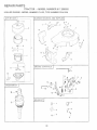
_0Assembly
o Operation
0 Customer Responsibilities
_ Service and Adjustments
Repair Parts
C
_AUTIONo
Read and follow
FOR CONSUMER
all safety
ASSISTANCE
rules
and
instructions
before
operating
HOT LINE, CALL THIS TOLL FREE NUMBER:
this
1-800-659-5917
equipment.
Safe
WMPORTANT:
THIS CUTTING
FAILURE
TO OBSERVE
THE
SAFETY
RULES
Practices
for Ride=On
Operation
MACHINE
FOLLOWING
GENERAL
,
Read, understand,
and follow afl instructions
and on the machine before starting,
,
Only allow
instructions,
o
Clear
which
',
Be sure the area is clear of other people before mowing.
machine
if anyone enters the area.
Never
OPERATION
adults, who
the machine.
are familiar
with
the
etc.,
Stop
necessary.
backing.
Always
Be aware of the mower discharge
direction and do not point
it at anyone.
Do not operate the mower without either the
entire grass catcher or the guard in place.
SIow down
before
turning.
o
Never leave a running machine unattended.
Always turn off
blades, set parking brake, stop engine, and remove keys
before dismounting.
•
Turn off blades
Stop engine
chute.
when
before
in daylight
removing
Mow only
o
Do not operate
the machine
alcohol or drugs.
o
Watch
for traffic when
o
Use extra care when
a trailer or truck.
_V. SERVICE
o
not mowing.
,,
grass
or good artificial
while
operating
loading
catcher
light:
under
the
near or crossing
or unloading
influence
of
Never
into
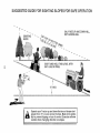
Slopes are a major factor related to loss-of-control
and
tipover accidents,
which can result in severe injury or
death. All slopes require extra caution. If you cannot back
up the slope or if you feel uneasy on it, do not mow it.
,,
,,
Mow up and down sIopes, not across.
Remove obstacles such as rocks, tree limbs, etc.
Watch for holes, ruts, or bumps.
Uneven terrain could
overturn the machine. Tall grass can hide obstacles.
Use slow speed. Choose a low gear so that you will not have
to stop or shift while on the slope.
Follow the manufacturer's
recommendations
for wheel
weights or counterweights to improve stability.
Use extra care with grass catchers or other attachments.
These can change the stability of the machir.
Keep all movement on the slopes slow and g;aduaL Do not
make sudden changes in speed or direction.
Avoid starting or stopping on a slope, if tires lose traction,
disengage the blades and proceed slowly straight down the
slope.
,
engine
Do not
indoors.
or fuel container
inside
Keep nuts and boks,
and keep equipment
especially btade attachment
in good condition.
Never tamper
with
operation regularly.
safety
devices.
where
heater.
Check
bolts, tight
their
proper
Keep machine free of grass, leaves, or other debris build-up.
Clean oil or fuel spillage.
Allow machine
to cool before
storing.
Stop and inspect
the equipment
if you strike
Repair, if necessary,
before restarting.
DO:
•
Theyare
there is an open flame, such as a water
Never run a machine inside a closed area.
o
,,
refuel the machine
Never store the machine
roadways.
the machine
Useextracarein
handli _gasolineandotherfuels.
flammable
and vapors _e explosive.
Use only an approved
container.
Never remove
gas cap on add fuei with the
running;
Allow engine to cool before refueling.
smoke.
or unclogging
WI. SLOPE OPERATION
•
OBJECTS,
OR DEATH.
Tragic accidents can occur if the operator is not alert to the
presence of children.
Children are often attracted to the
machine and the mowing activity.
Never assume that
children witl remain where you last saw them.
o
Keep children out of the mowing area and under the watchful
care of another responsibie adult.
Be alert and turn machine off if children enter the area.
o
Before and when backing, look behind and down for small
children,
Never carry children
They may fail off and be seriously
injured or interfere with safe machine operation.
o
Never allow children to operate the machine.
o
Use extra care when approaching blind corners, shrubs,
trees, or other objects that may obscure vision.
passengers.
Do not mow in reverse unless absotuteiy
took down and behind before and while
,
in the manual
the area of objects such as rocks, toys, wire,
could be picked up and thrown by the blade.
carry
FEET AND THROWING
IN SERIOUS
INJURY
III. CHILDREN
L
responsible
to operate
Mowers
IS CAPABLE
OF AMPUTATING
HANDS
AND
SAFETY
INSTRUCTIONS
COULD
RESULT
Never make adjustments
an
or repairs with the engine
object.
running.
Grass catcher components
are subject to wear, damage, and
deterioration,
which could expose moving parts or allow
objects to be thrown.
Frequently
check components
and
replace with manufacturer's
recommended
parts, when necessary.
Mower blades are sharp and can cut. Wrap the blade(s) or
wear gloves, and use extra caution when servicing them.
•
Check brake
required.
operation
f ,_quently.
Adjust
and
service
DO NOT:
,
o
o
disconnect
spark plug
wire and place wire where it cannot contact
spark
plug in order to prevent
accidental
starting
setting
up, transporting,
CAUTION: when
Always
j
adjusting
or making repairs.
Do not turn on slopes unless necessary, and then, turn slowly
and gradually downhill, if possible.
Do not mow near drop-offs, ditches, or embankments. The
mower could suddenly turn over if a wheel is over the edge
of a cliff or ditch, or if an edge caves in.
Do not mow on wet grass. Reduced traction could cause
sliding.
Donottrytostabilizethemachinebyputtingyourfootonthe
ground.
Do not use grass catcher on steep slopes.
WARNING
4&
The engine exhaust from this product contains
chemicals
known to the State of California
to
cause cancer, birth defects, or other reproductive harm.
2
as
CO_Grs_A _.LAo_©[iS
o"l your pumhase of a .:_eals
Traetor I[_"-_as
been des[qned,,.,engir:emed and manufactured Io give you the best possibie dependabiitv arid
Should you experience any probbm you cannot easiiy
remedy, piease contac[ your nearest Sears Authorzed
Sewice Cente_/DepaS:ment Department. We have corm
potent wetbtrained technicians and the proper too!s to
service or repair this tractor,
Please read and retain Ibis manual. The nstructions wll
enable you to assemble and maffstain your tractor pmper!y
Atways observe the '_SAFETY RULES".
•,1rJMBEs
9 t / ._5650_z
SERIAL
iNUMBER
! 5.0
GASOL NE CAPAC TY
ANC, TYPE:
t,25 GALLONS
_NLEADED REGULAR
OIL TYPE (APFSF/SG):
SAE IOW30 (above 32°F}
SAE 5W-30 (beiow 32°P)
OIt CAPACi]Y:
W/FILTER:
40PNTS
W/O FILTER: 3,5 PINTS
SPARK PLUG:
G£P: 040")
.._,AMP,JN
¢'_'
_ _ ' RC12YC
VA_.vl: ,.;LhARAN<;E;
NO'T, D..USTABLE
GROUND SPEED (MPH):
FORWARD: 0
T_RE _-'RESSURE:
FRONT: !4 PSI
REAR: !0 PSi
CHAR,s.NG SYSTEM:
3 AMPS BATTERY
5 AMPS HEADLIGHTS
5.5
REVERSE: 0-24
................................................................................
IUATL: OF P[J[:{C
qA,oE
H_ 71ODE<./_,NDSERi£,_ .}JMBERSWIL_.BET,JU,.ID
ON A PLATE UNDER THE SEAT.
YOU SHOULD RECORD BOTH SERIAL NUMBER AND
DATE OF: lo,,,.
-_i RCHASE
'
" AND KEEP IN A SAFE PLACE
FOR FU, URn=REFERENC_
.NAN¢_
AGREEMEN
F
A Sears Maintenance Agreement is avaiiabie on this produet Contact your nearest Sears store :[or detaiis
Read and observe the safety rutes
Foitow a _'eguiar schedute in maintaining, caring for arid
_',
HORSEPOWER:
Foilow the instructions under "Customer Responsibilb
des _kd "Storage" sections of this owne_ s manuak
WARNING:
This t_actor is equipped with an ntemat
combustion engine and shouid not be used on or near any
LH q TED TWO YEAR
WARRANTY
=
"BA rTERY:
AMP/HR:
MIi'4.CCfa,:
CASE SIZE;
30
240
UIR
I BLADE BOLT TORQUE:
30-35 FT. LBS
unimproved forest_covered brash,covered or grass-covered and unless the engines exhaust system is equipped
with a spark arrestor meetin¢] applicable locai or state taws
(if ar;y)_ f a spa,_ka testa s Used ii should be ma r_,tained
n effective working order by Ihe operator.
n the state of California the above is required by law
{Section 4442 of Ihe Caiifornia Pubic Resources Code}•
Other states may have simiiar laws. Federal laws apply on
federai !ands. A spad< arrestor for' the muffler is available
through your r_earest Sears Au[horized Service Cartier/
Depa_'ment (See REPAR PARTS section of this manual}.
ON ,JRAFTS[VIAN
" DING
F{
E@UIP aENT
For two ,,_)years from the date of pumhase,if this Craftsman Riding Equipment is maintained, iubdcated and tuned up according
to the nstrJctio<_sin the owner's manuai, Sears wit! repair or re,aiace free of charge, any parts found to be defective in material or
1'hisWarranty does hot cover:
o
Expendable items which become worn during normal use, such as blades, spark plugs, air cleaners, belts, etc.
Tire replacement or repair caused by puncturesfrom outside objects, such as nails, thorns, stumps, or giass.
o
Repairs necessar£ because of operatorabuse negligence, improper storage or accident or the faiiure to maintain the
equipment
according to the instructionscontained in the owners manuei.
'o Riding equipment usedfor commercial or reniai purposes.
L Ba TED 90 DAY WARRANTY
or
ON B qTERY
r_ff_ety(go} days from date of purchase, if any batteqi inck._dedwth his riding equipment proves defective in material or
and our testing determir_esthe battery witl not hold a charge, Sears will _ep!ace the baiter,/at no charge.
workmanship
N,-HOME WARRANTY SERVICE ON YOUR CRA_SMAN
RtD_NG EQ IPMENT IS AVAILABLE AT NO-CHARGE FOR 30
DAYS FROM THE DATE OF PURCHASE PLEASE CONTACT YOUR NEAREST SERVICE CENTER. AFTER 30 DAYS FROM
"r'HE DATE OF PURCHASE, WARRANTY SERVICE iS AVAILABLE BY TAKING YOUR CRAftSMAN
RIDING EQU!PMENT TO
YOUR NEAREST SEARS SERVICE CENTER. (!N.-HOME WARRANTY SERVICE WILL STLL St:!;iAVA LABLE AFTER 30 DAYS
FROM THE DATE OF PURCHASE BUT A STANDARD TRIP OflARGE WILL APPLY.') T'IS WARRANTY APPLIES ONLY
WI41LE THIS PRODUCT !S _NTHE UNITED STATES.
This Warranty gves you epecific egat fights and you may also have other _ignts which may _a_y from state to state
.'_c.ARo ROE[V£_<,KA 4_ wO,
"*• D/817 WA, _d¢.}
"-=-! s_AhESTA'FES, L
TABLE OF CONTENTS
SAFETY RULES ............................................................ 2
PRODUCT SPECiFiCATIONS ...................................... 3
CUSTOMER RESPONSIB_LmES ..................... 3. !5-t9
WARRANTY ..................................................................
3
TABLE OF CONTENTS ................................................. 4
iNDEX ............................................................................
4
TRACTOR ACCESSORIES ......................................... 5
ASSEMBLY ...............................................................
7-9
OPERATION .........................................................
10-14
MAINTENANCE SCHEDULE .....................................
15
SERVICE AND ADJUSTMENTS ........................... 20-25
STORAGE ...................................................................
26
TROUBLESHOOTING ...........................................
27-28
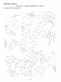
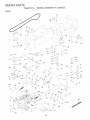
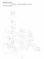
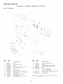
REPAIR PARTS - TRACTOR ................................
30-47
REPAIR PARTS- ENGINE ....................................
48-53
PARTS ORDERJNGISERV_CE .................. BACK PAGE
iNDEX
A
Accessories .......................................
5
Adjus_rnen_s:
Brake ........................................... 22
Carburetor .................................... 25
Mower:
Front-To-Back ...................... 2I
Side-To-Side .......................... 2t
Throttle Control Cable ................. 25
Air FHter, Engine ................................. 18
Air Screen Engqe ............................. '_8
Assembly ........................................... 7-9
B
Battery:
Charging ................................
78
Cleaninc ...................................... 16
Starting w_th Weak Battery ....... 24
Storage ......................................
26
Terminals .................................... I6
Belts:
Motion Drive
Removal/Repiacem_nt ........... 22
Mower Blade Drive
Removal/Replacement ............ 22
Blade:
Sharpening ................................... 16
Replacement ................................ 16
Brake Adjustment ................................ 22
C
Carburetor Adjustment ....................... 25
Controls, Tractor ................................. ! I
Customer Responsibilities .......... 3,I5-19
Engine:
Air Filter .................................... 18
Air Screen, Engine .................. 18
Battery ...................................... 16
Cooting Fins, Engine ............... 18
Engine Oil ................................ t7
Fuel Filter ................................ 19
Spark Plugs .............................. 18
Tractor:
Blades ...................................... t6
Lubrication Chart ..................... 15
Maintenance Schedule ........... 15
Tire Care ......................... 8,16,23
Cutting Height, Mower .......................... t2
E
E,_ectrical:
Interlocks and Reiays ................ 24
Schematic ................................... 29
Wiring Diagram ........................... 30
E_gine:
Air Filter .......................................
18
Air Screen ..................................
18
Cooling Fins Eng ne ................... 18
Oil Change .................................
17
Oil Level ................................. 13.17
Qi! Type
..................................
17
Preoara_tor ................................
13
Reoair Parts ........................... 48-53
Starting .......................................
4
Storage ...................................
2_
F
FlUters:
Air ...............................................
18
Fue_.............................................
19
Ft_ef
Type ............................................
13
Storage .......................................
26
Fuse ...................................................
24
G
Gauge Wheels ..................................... 8
H
F_'oodRemoval/installation ................. 24
L
Leve_ing Mower Deck ......................... 2!
Lt_brication Chart ................................ 15
M
Maintenance Schedule ...................... 15
Mower:
Adjustment, Front-to-Back .......... 21
Adjustment, Side-to-Side ........... 2!
Blade Sharpening ....................... 16
Blade Replacement ..................... 16
Cutting Height ............................. 12
Installation ................................... 20
Operation ............................... 12-13
Removal ...................................... 20
Mowing Tips .......................................
14
Muffier ................................................
t8
. Spark Arrester .......................... 3,40
Muicher Plate .......................................
9
O
Oil:
Cold Weather Conditions ....... 13,17
Engine .........................................
17
Storage ......................................
26
Ooeration
....................................
10-t4
Operating Mower ..............................
.12-I3
Ootions:
Accessories ................................
5
Seark Arrester ........................
3.40
P
Parking Brake ................................ 1 I-i2
Parts Bag ............................................
6
Parts. ReDlacementJRepair ........... 30-47
Product Specifications .........................
3
R
Reeair Parts ..................................
S
30-47
Safety Rules .......................................
2
Seat ......................................................
8
Service and Adjustments .............. 20-25
Brake ...........................................
22
Carburetor .................................. 25
Fuse ............................................
24
Hood Removal/Installation
.......... 24
Motion Drive Belt
Removal/Replacement
........... 22
Mower Blade Drive Belt
Removal/Replacement
........... 22
Mower Adjustment:
Front_to-Back ......................... 21
Side-to-Side ........................... 21
Mower Installation ....................... 20
Mower Removal .......................... 20
Tire Care ............................. 8,16,23
Slope Guide Sheet ............................. 55
Spark Plugs ........................................
18
Specifications .......................................
3
Starting the Engine ....................... ! 3-t4
Steering Wheel ................................ 7,23
Stopping the Tractor ........................... 12
Storage ...............................................
26
T
Throttle Control Cable Adjustment ..... 25
Tires ...........................................
8,16,23
Trouble Shooting Chart .................. 27-28
Transaxle Repair Parts .................
W
46-47
Warranty ...............................................
Wiring Diagram ..................................
Wiring Schematic ...............................
3
30
29
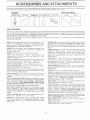
These
accessories
andattachments
wereavailable
through
most
Sears
ro_ail
outlets
andservice
centers
whenthetractorwaspurchased.
MostSears stores can order these items for you when you provide the model number of your tractor.
ENGINE
AiR FILTER
PERFORMANCE
Soars offers a wide variety of attach ments that fit your tractor.
you. This _istwas current at the time of publication; however,
may be made in these attachments, or some may n° longer
accessories and attachments
that ate available for your
Most of these attachments do not require additional hifches
attaching and detaching.
Many of the_seare listed below with brief explanations of how they can help
it may change in f_tUre years - more attachments may be added, changes
be available or fit your modet Contact your nearest Sears store for the
tractor.
or conversion kits (those that do are indicated) and are designed for easy
AERATOR promotes deep root growth for a heaithy lawn Ta
pered 2.5 inch steel spikes mounted on !0-inch diameter discs
puncture holes in soil at Cose intervals to Jet moisture soak in.
Stee we ght tray for increased penetrat on
BAGGER lets you cottect grass c}ippings and teaves for a
heafthier, nester looking iawn. Two Perrnanex containers hold
30-gallon ptastic bags.
BUMPER protects front end of tractor from damage.
CARTS make hauling easy. Variety of sizes available, plus
accessories such as side panel kits, tool caddy, cart cover,
protective mat and doily.
CORING AERATOR takes smafi piugs out of so_ to allow moisture and nutrients to reach grass roots, 36dnch swath. 24
hardened steel coring tips. 150 lb. capacity weight tray.
EASY OIL DRAIN VALVE makes oil changes easier, faster.
FRONT NOSE ROLLER canters in front of mower deck to reduce
chances of "scalping" on uneven terrain.
GANG NtTCN lets you tow 2 or 3 pull-behind attachments _t once,
such as sweepers, dethatchers aerators (not for use with toilers,
carts or other heavy attachments).
GAUGB WHEELS on both sides of the mower deck reduce
chances of"scalping" on uneven terrain• For mower decks not so
equipped.
MULCH RAKFWDETRATCHER !oosens soil and flips thatch and
matted leaves to lawn surface for easy pickup. Twenty spring tine
teeth. Useful to prepare bare areas for Seeding. Available forffont
or rear mounting.
RI_GH PERFOR_d_ANCE REEL_ACTION
SPRING T_NE DETHATCHER covers 36-inch wide path and
tosses thatch into large hopper, Mounts behind tractor,
MULCHING CLOSE-OUT PLATE K_T, once instaJied, Jets you
muich, discharge or bag clippings (bagger optional) wi[hout
changing blades. For models not equipped as 3din1 Convertible
mowers.
See "MOWER" in the Repair Parts section of this
manuai,
RAMP TOPS AND FEET let you load and unload tractor from a
pickup truck. Use with 2 x 8 or 2 x I0 Iumber.
ROLLER for smoother iawn surface.
36dneh wide, 18dnch
diameter water-tight drum holds up to 390 Ibs_of weight. Rounded
edges prevent harm to turf, Adjustable scraper automatically
cleans drum.
S#_OWBLADEIorsnowremovatorfiy.
14dnch high,48dnchwide
_;adec_ears42-inch pathwhen angledld_or dghL Ra!Ses, lowers
_;_rlside tever: Adjustable skids; repiaCeabJe, revers Ibte scraper
ba_. (Use with t re c qa ns'and whee we ghts and/or rear drawbar
SN()_,P_HROWER has 40dnch swath. Drum-.type auger handles
powdery and wet!heavy snow. Mounts easily with simple pin
arrangement. Discharge chute adjusts from tractor seat. 6dnch
d_ameter spout discharges snow 10 to 50 feet. Lift controlled at
tactor seat. (Use with chans and wheei weights and/or rear
SPRAYERS use 12welt DC electric motor that connects to the
lractor batten/ or other 12-volt source.
Includes booms for
automatic spraying and hand he!d wand for spot spraying, Wand
fas adjustaMe spray pattern. For apptying herbicides, insecticides, fungicides and liquid fertilizers.
SPREADBRiSEEDERS make seeding, fertilizing, and weed kilt_sg aasy_ Broadcast spreaders are also usefuI for granular deicers and sand.
'Sh_JE:EPERSlet you coi/ect grass c ippings and leaves.
!;_I:and depth control system and does NOT reqL 'e a s eeve hitch
R{Sany iawn, yard Orgarden tractor. Simply hook up to the tractor
a_awbar and g0! Optional
accessories
convert unt for
@thatching, aerating hilling...without tools.
T_RBCHAINS are heavy duty; ciOsety spaced extra-large cross
}}_ks give smooth ride, outstanding traction.
*fRAC_OR CAB has heavy duty vinyt fabric over tubular steel
frame, ABS piastiC !op; ciear p!astic windshield offers 360 degree
visibility: Ringed 'netai doors with catch. Keeps operator warm
and dv
Remove vinyl sides and WindShields for use as sun
_:,roi_ct0r in summer, Optio_"_a! accessories
include:
tinted/
tempered s0iid Safety
• glass W nc she d Wth harid operated wiper;
12-volt amber caution }ight for mounting on Cab top.
stACS for poweffui coitection of heavy grass c!ippihgs and leaves,
O#tio_at wand attachment to pick up debris in hard4o_reach
p_aces. VACiCH_PP_R includes a chipper-shredder,
W_!GHT BRAC_(_T for drawbar for snow removal applications.
Jses (..,.
t_ <5 lb. weight.
_HBEL WB_GHTS for rear wheels provide needed traction for
,ate,
snow removal or ._ozing heavy *r ct_e
_.+ _u
,,
OF H
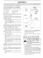
RaGs Bag oontents
E
shown 'full size
Parts packed
separately
in carton
) Hex Bo_t
8/8 I6 x I
_4
/
/
/,
Ses.t
/
Video
Cassette
f
/
/
',
(I) Lar@eFiat Washer
/
/ i
/
(t) U>ckwasher 318
q
7Yhee,
(i) Locknut
5/I6-,!8
_{?lbleher
Plate
(1) I4ex Boit 5/16-18 st i-I_4
{{...........
i
Boot
Manua
{1) Hex Bolt
!/213 x i
i
Parts Bag
(!} Washer
/"
I.-3ll £x 12
Gauge
/
!j'
(1} Leck Wad-her i/
(2) Screws
#10x 518
#10
\
(2} Centerlock Nuts
(2) Keys
\
8/16 x 3/4
x 16 Gauge
_
(2) Wetd
Nuts #10
Assemblys
tt
}} Wheel
\}, ..................
//
lnser_
(2) Hex Bo!ts I/4-20 x 3/4
(2) Hex Nuts 114.__.0
z_ Washers
9/32 x 518 x _ Gauge
Extension
bnafl
Yournewtractorhasbeenassembled
atthefactoryw_thexceotion
of hose parts left unassembled for shipping purposes.
To ensure safe and proper operation of your tractor all carts and hardware you assemble must be figr_tened securely. Use
the correc_ loots as necessary to insure proper tJghmess.
TOOLS
REQUIRED
FOR ASSEMBLY
STEERING
--.'_ WHEEL _NSERT
A socket wrench set wilt make assembly easier. Standard
wrench
sizes are Iisted.
(2}
9/I6"
When right or eft hand is mentioned
means when you are in the operating
behind the s_eermg wnee_ !,
UNPACK
WASHER
°_.
STEERING
WHEEL
-"
m rots manual, it
oosition (sea_ee
STEERING
BOOT
_
.....
TRACTOR FRON! CARTON
CARTON
AOAPTER,.
Cut,
from top
bottom,
of carton,
andtoIay
panelsatong
fiat. lines on alt four comers
Check for any additional loose parts or cartons and
remove,
EXTENSI!ON
-
Remove al accessible loose oa_s ana carts canons
Trom capon (See page ] L
,
3/8 HE:X BOLT
318 LOCK WASREF!
Tire oressure gauge
Utility knife
wrench
TO RE,lOVE
.......
.........
I _ 3/4" Secket w/afire rachel
Philliss Screwdriver
tU 5J16" wrench
_2t 7/!6" Nrencnes
_ _ //2" wrer_cn
/
SHAFT
5/16HEXBOLT
.,. :
_J
1
_ .'i! -:-, _'
4
5/,6
LOCI(NUT
i
,/
'
-
:
/
" ....
_
"
.
"
BEFORE ROLUNG TRACTOR OFF SKID
A°FACH
ASSEMBLE
STEERiING WHEEL
(See Fig, 1)
EX'TENSION SHAFT AND BOOT
F_G. !
Slide extension shaft onto lower steering shaft, Align
mounting holes in extension and iower shafts and
install 5/t6 he>:bolt and Iocknut. Tighten securely.
I_tPORTANT: TIGHTEN BOLT AND NUT SECURELY TO
18_22 FT LBSTORQUE.
o Place tabs of sleeting boot over tab slots in dash and
push down to secure.
iNSTALL STEERING WHEEL
o
o
o
o
Position front wheeis of the tractor so they are pointing
straight foPTvard.
Slide steedng wheel adapter onto steering shaft extension.
Place freewheel control in freewheefing position to
disengage transmission (See "TO TRANSPORT ° in
the Ogeration section of this manua!).
Roil tractor backwards off skid.
Remove banding holding discharge guard up against
tractor
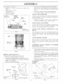
HOW TO SET UP YOUR TRACTOR
CONNECT
Position steering wheel and sleeve assembly so cross
bars are horizenta! (left to right) and slide onto adapter.
Assemble large fiat washer, 3/8 iock washer, 3/8 hex
bolt and tighten securely
Snap steering wheel insert into center of steering
wheel.
Remove protective pastic from tractor hood and grill.
IMPORTANT: CHECK FOR AND REMOVE ANY STAPLES
IN SKID THAT MAY PUNCTURE TIRES WHERE TRACTOR
IS TO ROLL OFF SKID.
o
Press rift lever p{unger and raise attachment lift lever to
its highest position
Reiease parking brake by depressng clutch/brake
(See Figs, 2 and 3}
CAUTION: Do not short battery term_
na_s: Before eormecting batterj_ re_
move metal bracelets,
wristwatch
bends, rings_ etCo
Positive terminal must be connected
first to prevent sparking from acciden-
o
e
TO ROLL TRACTOR OFF SKID (See Opera°
tier section for tocation and function of con.,,
BAKERY
Remove cardboard packing from seat pan and tiff seat
pan to raised position.
Open battery box door.
Remove terminal proteciive caps end discard.
If this batten/isput
into service after month and year
indicated on label (!abel located between terminals)
charge battery for minimum of one hour at 6-10 amp&
First connect RED batter,! cable to positive (+) terminat
with hex boit, flat washer, lock washer and hex nut as
shown, T ghten securely.
Connect BLACK grounding eabte to negative (-}_ferminai with remaining hex bott flat washer lock washer
and hex nut. Tighten secureiy_
Close battery be)( door.
ASSE
Open battery box door lot':
o
Inspection for secure corlnections (to _ig_'ten hard
_*
o
Inspection Ior corrosion.
Testing batteG,
Jumping (f required}
Periodic ci_arging.
POSIT!VE
{RED) CABLE
o
/
'
CAPS
NUT
The tires on your tractor were overinfiated at the !actor/for
shipping purposes. Correct tire pressure is irnpoRant for
best cutting pedormance.
LOCK
WASHER
/
i
Lower seat into operating position and sit on seat.
Slide seat until a comfortable position is reached which
a!ows you to press dutch/brake pedal a_I the way
down,
Get off seat without moving its adjusted position.
Raise seat and tighter adjustment bolt securely.
CHECK TIRE PRESSU!!_E
B_SCARD
TERMINAL
, PROTECTIVE
.-..
o
/
Reduce tire pressure to PSI shown n "PRODUCT
SPECIFICATIONS" on page 3 of this manual.
PLAT
WASHER
HEX
BOLT
NEGATIVE
CHECK ©ECK LEVELNESS
For best cutting results, mower housing should be properly
leveled. See "TO LEVEL MOWER HOUSING" in the
Sewice and Adjustments section of this manual•
CHECK
FOR
PROPER
POSITION
OF
ALL
(BL ACE) CABLE
F_G....
See the figures thai are shown for replacing motion and
r_iower _lade @;ire betts in the Sergice and AdjustmentS
section of Ibis manual, Verify ihat the belts are rouIed
SEAT
PAN
After you ieam how _o operate your tractor, check to see
that the brake is propedy s.diusted, See "TO ADJUST
BRAKE' in the Service and Adjuslments section of this
rnanual_
BATTERY
BOX DOOR
ASSEMBLE
GAUGE
WHEELS
TO MOWER
DECK (See Fig. 5)
Assemble gauge wheeis with tractor on a flat level surface
,_
Adjust mower to desired cutting height (See "TO ADJUST MOWER CUTTING HEIGHT" in the Operation
section of this manual),
-_
Wth mower in desired height of cut position, gauge
wheels should be assembled so they are slightly off the
ground. Install gauge wheel in appropriate hole with
shouider bolt, 3/8" washer and 3/8o16 tocknut and
tighten securely.
,,
Repeat for opposite side installing gauge wheel in
same adjustment hole.
FtGo 3
_NSTALL
SEAT (See Fig° 4)
Adiust seat before tightening adjustment bott
o
Remove cardboard packing on seat pan
0_ Place seat on seat pan and assemble shoulder bolt.
Assemb!e adjustment boIt bck washer and fiat washer
looseIy Do not tighten.
Tighten shoulder boit securety
]
l
SEAT
/"
\
SEATPAN
3/8- t 8
GAUGE WHEEL j ..... k
F'iGo4
FIG,, 5
SHOULDER
BOLT
_NSTALL MULCHKR
{See Figs. 6 & 7}
PLATE
Install two a[cn nooks _o mutcher p_a[e using screw,
washer, IOCKwasner, and wetd nut as shown,
NOTE: Pre-assembie wetd nut to latch hook by inserting
we_a nut from the top w_th hook oointing down,
Tighten hardware ;ecure_y.
Raise and nolo deflector shield in Jprlght position,
Place front of muiener orate over fret t of mower deCK
opening and slide into p_ace, as shown.
Hook front latch trio note oR front of mower deck
o
Hook rear latch into no_e an back Of mower DecK.
CAUtiON:
Do not remove discharge
guard f_om mower. Raise and hold
guard when attaching muJcher plate
and allow it _o rest on p_ate whi_e in
LATCH
HOOKS
FiG. 7
HOOK POINI"S DOWN
WELD
NUT
FROM
THE
TOP jr
.......
_
X\
BEFORE YOU OPERATE AND ENJOY YOUF_ NEW
TRACTOR. WE WISH TO ASSURE TH/I T YOURECEfVE
FHE BESTPERFORMANCEAND
SA TtSFA C TION FROM
FHIS OLIAL/TY PRODUCT,
"'S
LOCK
PLEASE REVIEW THE FOLLOWING CHECKLIST:
LATCH
J"
LOCK
WASHER
WASHER
HOOK
WELD
NUT
WASHER
MULCHKR
PLATE
FIG, 6
TO CONVERT
DiSCHARGiNG
TO BAGGING
OR
Simply remove mulcher plate and store in a safe place.
Your mower is now ready for discharging or installation of
optional grass catcher accessoPy,
NOTE: It is not necessary to changebtades, The mulcher
blades are designed for discharging and bagging also,
/
All assembly instructions have been completed.
/
No remaining !dose parts in carton.
_/
Battery is properly prepared and charged,
1 hour at 6 amps).
v"
Sea {,iS adjusted comfortably and tightened securely,
v'
Atttires are properly inflated. (For shipping purposes,
the tires were overinfiated at the factory).
(Minimum
_x Be sure mower deck is properly leveled side-to-side/
frontqo-rear for best cutting results. (Tires must be
properly inflated for ieveiing),
/
Check mower and drive belts, Be sure they are routed
properly around pul!eys and nside all belt keepers.
/
Check wiring. See thai aH connections are stiil secure
and wires are properly clamped.
v"
Before driving tractor, be sure freewheel control is [n
drive position_
WHILE LEARNING HOW T© USE YOUR E_ACTOR, PAY
EXTRA ATTENTION TO 7-HEFOLLOWING IMPORTANT
FFE/MS:
v"
Engine oil is at proper !eveL
/
Fuel tank is fiIled with fresh, clean, regular unleaded
gasoline.
Become familiar with alt controls ,- their location and
function. Operate them before you start the engine.
/
/
Be sure brake system isin safe operating condition.
v'
II is important to purge the transm ssion before operating your tractor for the first time_ Fotlow proper starting
and transmission purging ins!ruetions (See "TO START
ENGINE" and "PURGE TRANSMISSION'
in the Opt.
e_ation section of this msn/4aI)
Thesesymbol,_
mayappearor yourtractorofinJ[terature
supplied
withtheproduct.Learnandunderstand
theirmeaning.
,-- __,,
o
CAUTIONOR
WARNING
REVERSE
FORWARD
FAST
SLOW
i
_
EN (_'.xJN_z:
ON
ENGINE OFF
_, O_._
JJL PRESSURE
_
_ I (..,'t
_L
C__U
C_"
MOWER
_ ....
LOCm
RLVERoE
NEUTRAL
HIG_
MGHTS ON
_
PARi41NG BRAKE
LOCKED
LOW
LIGHTS OFF
UNLO_._'..E_J
PARKING BRAKE
÷
lvlO \NER LIFT
ATTACHMENT
CLUTCH ENGAGED
'_ _
_
/E_
• •
DANG_, _',._::
._D HANDS AND FEET AWAY
ATTACHMENT
CLUTCiq DISENGAGED
(_ydro Moee _ o y
IGNtT Ob
ii
READ THIS OWNER"S
MANUAL
AND SAFETY
RULSS
BEFORE
OPERATING
YOUR TRACTOR
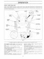
Compare the illustrations with your tractor to familiarize yourself with the iocati0ns of Various controis and adjustments.
this manual for future reference_
LIGHT
SWITCH
POStT_ON
IGNmON
SW_TCH
AMMETER
Save
\
THROTTLE/
CHOKE
CONTROL
,,
PLUNGER
ATTACHMENT
LIFT LEVER
CLUTCHf
BRAKE
PEDAL
ATTACHMENT
CLUTCH LEVER
HEIGHT
ADJUSTMEN_
KNOB
FREEWHEEL
CONTROL
PARKING
iI"-:!!LII
¸.
BRAKE
CONTRoLMO
_
APPROX.
LEVER
SPEED
3
FiG. 8
Our tractors conform to the safety standards of the AmeriCan National Standards institute.
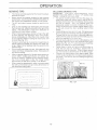
MOTION CONTROL LEVER - Selects the speed and
direction of the tractor,
ATTACHMENT CLUTCH LEVER: Used to engage the
mower blades, or other attachments mounted to your
tractor.
UGHT SW_TCN: Turns the headlights on and off.
ATTACN_'_IENT U_ LEVER: Used to raise and lower the
mower deck or other attachments mounted to your tractor.
THROTTLF__JCHOKE CONTROL:
controlling engine speed.
LIFT LEVER PLUNGER: Used to retease attachment lift
_ever when changing its position.
Used for starting and
CLUTCH/BRAKE PEDAL: Usedfordeciutching
ng the tractor and s_a_ing the engine.
PARKING
BRAKE:
Locks clutch/brake
peda
and brak-
_GN_TION SW_TCN: Used for starting and stopping the
engine_
!4EIGHT ABJUSTMENT
KNOB: Used toadjustthernowe__
into the
FREEWHEL CONTROL: Disengages transmission for
pushing or slowly towing the tractor with the engine off,.
A_I_4ETER: Indicates battery charging (+) or dischergi _g
!!
_' °"
TRA_J R9 H
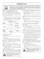
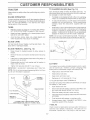
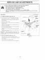
TO SEX"PARKH!G BRAKE {See Fig_ 9)
You tractor s equipped with an operator p esence sensing
switch.
When engine is running, any attempt by the
operator Io eave the seat without first setting the parking
brake wiil sPut off the engine,
Depress dulch/brake pedat into fuli "BRAKE" position
and hold
P/acs_parking brake iever in "ENGAGED" position and
release pressure from ch4ch/brake pedai Pedal shou!d
remain in "BRAKE" pos tion. Ma_<es_ze parking brake
will llold tractor secure.
A_iTACHMENT
CLUTCH
LEVER
TO US_:£TRRO_L£
CONTROL
(See Fig. 9)
Always operate engine st fuji throttle.
Operating engine at less than ful throttle reduces the
battery charging rate.
o
Fuii thro@e offers the best bagging and mower pefforo
rT_ance,
TO _",aOVEFORWARD
AND BACKWARD
(See
F_go9)
The direction and speed of movemerit is controiled by the
motion control lever
Start tractor with motion control !ever in neu[rat (N)
o
o
Release parking brake and clutch/brake pedal.
Slowly move motion control !ever to desired position.
'_@_SENGAGED"
p
j,
POSITION
PARKING BRAKE
"ENGAGBD"
GEARSHIET
.....LEWR
CLUTCH/
BRAKE
PEDAL
"DRIVE'
POSKION
HEIGHT ADJU
MENT _NO8
"_
Uo_, _ON
F_G°9
STOPPerinG (See Fig, 9}
MOWER BLADES ..
o Move attac _ment ciutch ieve' to 'DISENGAGED'* po
sition_
GROUND DRIVE_, Depress clutch!brake pedai nto _uit _BRAKE_'positieh_
Move motion control lever to r eutral (N) position,
!MPOATAHT:
THE MOTION CONTROL LEVER DOES
NOT RETURN TO NEUTRAL (N) POSIT!ON WHEN THE
CLUTCH/BRAKE PEDAL IS DEPRESSED,
ENGINE Mow_ _hrottJe control to slow (_)
pos tiom
NOTE
Faiiure to move throttie centre to sio,¢_ (_)
position and ai owing engine to die before stopping rnay
cause engine to 'backfire",
Turn ;gnton key to "OFF' position and remove key.
Always remove key when !eaving tractor to preve@
unauthorized use.
o Never .;se choke to stop engine.
NOTE: Under certain conditions when tractor s standing
die with he engne runnin% h@:erK3 ne ex iaus[ gases may
cause "browning* oi grass. To e iminate this possib@!_
always stop engne when stoppin{} tractor ors grass areas
CAU°_'IOH: A_ways stop t_'actor com_
p_ete% as described above before _eav,hg the operator's position:; to empty
grass catcher_ etCo
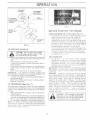
TO ADJUST
MOWER
CUTTING
HEIGHT
(See isig,,g}
The cutting height is controlled by turning the height adjustmast knob n desired direction,
-. _xrn kK)b c!ockwise (,S:,q) to raise- c_tting height,
*_
-%ira kieb counterclockwise (_-%) to lower cutting
The cutting height range is approximately I o1/2" to 4" The
heights are measured from the g,_oundto the blade tip with
the engine not runnihg. These heights are approximate
and n_ay van/depending
upon soil conditions, height of
,grass ad types of grass being mowed.
The average lawn shoutd be cut to approximately 2ol/2
nches during the cool season and to over 3 inches
during hot months. F:or healthier and better ooking
lawns mow often and after moderate growth,
_0 For best cutting pedormance_ grass over 6 inches in
height should be mowed twice. Make the first cut
releNvely high; the second to desired he ght.
TO OPERATE
_VtOWER (See Fig, 10)
Your tractor is equipped with an operator presence sensing
switch, Any attempt by the operator to leave the seat with
the engine running and the attachment clutch engaged wil!
shut off the engine,
Select desired height of cut
,_ Lower mower with attachment lift control
S_art mower blades by engaging attachment clutch
control.
_
TO STOP M©WER BLADES - disengage attachment
clutch control.
without
either
grass
CAUTION:
Dothe
noter_tire
operate
thecatcher,,
mower
o_ mowers
so equipped,
or the dis-
"EN@AGED"
POSITION
ATTACHMEHT
LOW
i V
HEIGHT
ADJUSTMENT
KNOB
CHECK
=,
GL_ABO
k....
FIG. I0
TO OPERATE
o
o
ON HILLS
Choose the slowest speed before starting up or down
hi!ls.
Avoid stopping or changing speed on hils.
if sbwing is necessary, move throttle controi tever to
f stopping is absoiutely necessa%,, push c_uth!bn_ke
pedal qu ckiy to brake pesitk)n and engage parking
brake.
_
Move motion control tever to neutrat (N} positior.
It_PORTA_t"[':
THE MOTION
CONTROL
LEVER DOES
NOT' RETURN TO NEUTRAL (H) POSKION WHEN THE
CLUTCH/BRAKE PEDAL JS DEPRESSED.
o TO restart movemenl, stowiy retease parking brake and
o
o
Slowly move motion control lever to slowest setting.
Make a! turns slowly.
TO TRANSPORT
{See Fig= 1!}
When pushing or towing your tractor, be sure to disengage
transmission by placing freewheel control in freewneetng
position Free wheel control is located at th,e resr@awbar
of tractor.
o
Raise attachment Iift to highest position with attach°
ment tift control.
o
PuiJf_eewhee! controi knob out and hold in position by
inserting retainer spring into foP_uardhoie of control rod.
o
Do not bush or tow tractor" at more than t:we {2} MPH.
°
To reenijage transmission, reverse above procedure
_,_O'/'E: To protect isood from damage when transporting
your t:ac o_ on a truck or a traiter, be sure hood is closed
and sec ire Sto t_actor. Use an appropr a_e means 9f tying
hood o t_actor (rope co_d, etc.).
ENGINE OIL L£VEL
(See Fig. 17}
rise engine t- yoJ_ t<ac or has been shipped, from the
factory, already flied ws summ,e_ weight oii.
Check engne oii wh '.tae_or on ievei ground.
gffhread a_d _'emove o
cap/dbstick
wipe oil off
Re nse_-the a ps! ck <:to ;he tube and est oil fii! cap on
the tube. Do not h_ead the ei@onto Ihe tube. Remove
and read o! eve
_:_cessary add oil un! 'FULL"
;na_k on d pstic_<is _esched Do r_ot overt 1_
£or cold weather operation you st ould change oi! for
easier starling (See OL VISCOS TY CHARW n the
Castomer Ressonsl:
ties section of this nanua0o
To change e _gine oi, see the C ;stomer Responsibifities section n t!qs Y,a .ai.
TO S_£R f ENGBIE
(See Fig_ 9)
PURGE TRANSMISS_ON
When starting d'_eengine for the first time or f the engine
has run out of f_.e, it will take extra crar_king time _o move
fuel from the tank to the engine.
_
Depress clutch/brake pedat and se_ parking brake.
Place motion control lever in neutral (N) position.
b;iove attachment c!utch to "DISENGAGED" position_
Move throttte control to choke (l_.i) position.
Note: Before starting, read the warm and cotd starting
procedures below.
o
!nsert key into ignition and turn key clockwise to "START"
positior_ and reiease key as soon as engine starts. Do
not ;un starter continuously for more than fifteen sec-.
ends per minute, tf the engine does not start after
several attempts, move throt£Je controJ to fast (@)
position, wait a few minutes and try again, f engine sfiIJ
does not start:, move the throttJe controi back to the
choke (t'q) position and retry',
',/?ARM WE.A_sJ
_::_ R oc'-_AR,T
txG_
__"/50 ° F arid above)
When engine s*a
._,._mo
'_" _move' the ,_
,_hrot.._
.r f_:_-,
.o i troJ to Ihe fast
(@} position.
]"he attachments and ground ddve cart now be used. if
the engine does not accept the end, restart the engine
and allow it to warm up for one min£e using the choke
as described above.
COLD WEATHER
o
STARTING ( 50° F and beow)
To ensure proper operation and perfomlance, it is recommelsded that the transmission be purged before operating
tractor' for the first time. This procedure wiit remove any
trapped air inside the transmission which may have develo
oped dudng shipping of your tractor.
_B._PORTANT:SHOULDYOUR TRANSMiSSiON REQUIRE
REMOVAL FOR SERVICE OR REPLACEMENT,
IT
SHOULD BE PURGED AFTER REINSTALLATION
BEFORE OPERATING THE TRACTOR.
P'.ace tractor saifeiyon tevet sudace with engine off and
parking brake set.
Disengage transmission by placing freewheel control
in freewheeling position (See "TO TRANSPORT" in
this section of manuai).
Sitting in the tractor seat, sta£ engine. After the engine
is running, move throttle controi _9 stow 0 position.
With motion control iever in neutral (N) position, slowly
disengage clutch/brake pedal:
,_ Move motion control iever to full forward position and
hold for five (5} seconds Move lever to futJ reverse
postion and hold for five (5) seconds. Repeat this
procedure three (3) times.
NOTRE: During this procedure there wiit be no movement of
drive wheels. The air is being removed from hydraulic drive
When eng r_estarts, allow engine to run with the throttle
cont_oi n the choke (ikl) position unfit the engine runs
roughly, then move throttie control to fast (_) position.
This may require an engine warm-up period from
severaJ seconds to several minutes, depending on the
HYDROSTAT
C TRANSMISSION
WARM LIP
Before driving the unit in cold weather, the transmis.
sion should be warmed up as follows:
"_ Be sure the tractor is on level ground.
_ Place the motion control lever in neutrat.
Re/ease the parking brake and let the chJtch/brake
slowly return to operating position,
Allow one minute for transmission to warm up.
This can be done during the engine warm up
The attacf ments can also be used during the engine
warm.<@ period afterthe transmission has been warmed
Ijp,
NOTE: If at a figh aititude (above :3000 feet) or in cold
temperatures (below 32 F) the carburetor fuel mixture may
need to be adjusted for best engine performance. See "TO
ADJUST CARBURETOR" in the Sewice and Adiustments
section of this manuak
o
Move motion control lever io neutral (N) position. Shut °
off engine and set parking brake_
Engage transmission by placing freewheel control in
driving position {See"TO TRANSPORT' n this section
of r,_anual).
Sitting in the tractor seat, sfart engine. After the engine
s running, move throttie control io hail (1/2) speed.
With motion control tever in neu_rat (N) position, slowly
disengage clutch/brake pedak
S!owiy move metion control /ever forward, after the
tractor moves approximafe]y five (5) feet, slowly move
motion contm_ bver to reverse position. After the
tractor moves approximately five (5) feet return the
motion controi _everto the neutraJ (N) position. Repeat
this procedure with the molion controt lever three (3)
times,
'Four tractor is now purged and now ready for normal
OPER
V OW NG TIPS
_1ULCH_NG _._fOW_NGT_PS
o
Tirechainscannotbe usedwhen themower housingis
attachedtotracto_
_,
_
Mower shouldbe properlyleveledforbest mowing
performance. See"TO LEVEL MOWER HOUSING _'n
the Sewice and Adiustments section of this manuai.
Fhe left hand side of mower shoutd be used for trimruing.
Driveso thatcfippings
ae dischargedonto thearea
thathas been cuL Have thecutarea.
totheright
ofthe
tractor.
Thiswi!l
result
ina more even distribution
of
clippings
and morn uniformcutting,
When mowing largeareas,start
by turning
totheright
so thatciippings
willdischargeaway from shrubs,
fences_driveways,
e_c.Afterone or two rounds,mow
inthe oppositedirection
making left
hand turnsunti
finished
(See Fig _2 )
Ifgrass isextremelytail,
itshouldbe mowed twiceto
reduce oad and possiblefirehazardfrom driedclip-.
pings.Make first
cutrelatively
high;thesecond o the
desiredheight.
Do notmow grasswhen its wet. We[ grasswill
plug
mower and leave undesirable clumps: A!tow grass to
dry before mowing.
Always operate engine at full throttle when mowing to
assure better mowing performance and proper discharge of ma_eriat Regulate ground speed by seiect_
ng a low enough gear to give the mower cutting
performance as v_ellas the quaiity of cut desired.
When operating etlachments, select a ground speed
that will suit the terrain and give best perferrnance of
the attachment being used.
o
o
o
o
o
]ON
FIG. 12
_PORTANT:
r.JR B.__ PERFORMANCE
KE£1_
,_,_OWERHOUSING FREE (Yx BU}LT-UP GRASS AND
TRASH CLEAN At:TEl E_.CH USE{
The speciai muiching b_ade wilt recut the grass clip.
pings many times and reduce them n size so that as
they faii .....
un_,_th_
" _ '_awn i:-_eywill d sperse rite the grass
and not ,._._'_
noticed. Aiso_ the mutched grass will
u,ua_g d_e quickiy to !J,o_ ,_e nutrients for the awn.
Always mulch witb_your ,lg,_,_..,
'_* _<÷ engine (Made) speed
as this wiiI provd_.Sthe best recutting action of Ihe
biades,
Avoid cutting your iawn when it is weL Wet grass tends
to form chimps and inte_eres with the mulching action.
The best time to mow your !awn is the early afternoon°
At this time the_a
_' nao_-_
d c:nd
...... ne new y cut area
:er_s,:_
,Jie._
wiil not be exposed to the direct sun.
oor best re_utts, adjust the mowe_ cutt ng he ght so that
the mower cuts off only £he top one-third of the grass
biades (See Fig. i2A). F:>rextrerneiy heavy mulching,
_'educeyour width of cut and mow slowly.
condkions may re-.
a second time to
eornpie e y hide the clippings. When doing a second
cui, mew across or perpend cuiar to the firsi cut path.
Change your cutting pattern from week to week. Mow
north te south one week then change to east to west the
next we_.K. This will i'ep prevent matting and oraininc
el the awn,.
i taAx _/s
ER REI
tLITtES
SERVICE DATES
Check
Brake Operation
[
L Check Tre Pressure
Check for _Bose Fasteners
Shaq:.ten/Reptace
Lubrication
Chock
Mower Blades
Cha4
Battery Lovei/Recharge
i- Clean Balery and Terminals
k
i Che_k Transaxie Cooiin 9
Adjus
Blade Beit(s) Tension
I
Ad ust Motion Drive Bek(s) Tension
/
Check
Engine
Oil Love
Ii Cha%ge Engine Oil
C ean Air F;ter
,
i...............................................
i Clean Engine Coo!ing Fns
Replace
}park
............
_ ............
PN_g
.......'
I..........
[
:>_IW
F
i
i
Replace
L
- Change
more
often
when
more
often
vw_en oeerating
If eaaipped
4 - Replace
GENER£L
wilh oil filte_
blades
more
operatk!
change
oHen when
9 under
a hea,_ f ioad
in dirty or dusty
oi
every
mowing
ot in high all
cot _Jitions.
in sandy
sol.
REOOMME , ©AXIONS
Some adjustments win need _o be made periodicaily to
properly maintain your tractor.
All adjustments in the Sen/ice and Adjustments section of
this manual should be checked at least once each season.
Once a year you should replace the spark plug clean
or replace air filter and check blades and belts for
wear. A new spark plug and clean air filter assure
proper air-fuel mixture and help your engine run better
and last longer.
BACH
US_
_,.,l_ec_..r,glne oil level
,., _,:;.!4 tlre
,_
pressure.
Chec( for Bose !asteners
bienl tempera{urea.
5 - If equipped
6 - Not
7
50 hours
The warranty on this tractor does not cover items that have
been subjected to operator abuse oF negligence.
To
receive futI value from _he warranty, operator must maintain
tractor as instructed in this manual
BEFOR_
LJ2_
f
Fuel Fiiter
2 - Service
3
I
!
¢W
I
Bapl
F--
red,sired
Tirhtep
Do not
frort
with
ad ustabie
if equipped
axle pivot
overt ghten
system,
with
maintenance-free
bolt to 35 ft,-Ibs< maximum
battely.
ES
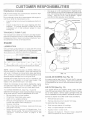
TO SHARPEN
Always
nance.
observe
BRAKE
safety rules when performing
any mamte_
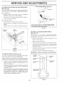
BLADE (See Fig, '14}
Sate £n}uld be _aKen to keeu :he blade oaancedo An
unbalanced blade w_! cause excesswe wbration and evem
_ual eamaae [o _ewe_ ar_a engine.
OPERATION
The blade can be sharpened with a file or on _ grinding
wheel Dc not attempt to sharpen while on the mower.
_ttractor requires more than six f6} feet stooping distance
st h_ghsseed in hignesx gear. then brake must be adjusted.
See "TO ADJUST BRAKE' '_ the Service and _,djusP
rnents section of this manua_l.
To check blade rsa_ance,you _al_neecJa 5/8" diameter
steei bott ore. or a cone oaiancer. When using a cone
bB]ancer. 1oucw [he nstructlons sursoJied with oaf
3RcBrL
T_RES
o
o
Maintair proper a_r pressure in alt tires ISee 'PRODUCT SPECIFICATIONS" on page 3 of this manuah.
o
Keep tires free of gasoline_ oil, or insect control chemicals which can narm rubber,
Avoid stumps, stones, deed ruts. sharp objecls abe
omer nazaras that may cause tire damage.
BLADE
Slide blade on to an unthreaded portion of the stee! bott
ar p_nano hold the Bolt or pm natalie with the g ouna.
I blade _sbatanced _1snoutct remain tn a horizontal
eosition, f either ena of the blade moves downwaro.
sharpen the heavy ena until the blade is Balanced.
NOTE: Do not use a nail for balancing blade. The _oDesof
En<_
cen_e_"hole may aE;oearto De cen'iered but are no_
CENTER HOLE
CARE
For best results mower blades must be Rep; snarD. Re-p_ace Den[ or aamagea blades.
BLADE
REMOVAL
(See Fig, 13)
o
Remove hex bolt, iock washer and fiat washer securing
blade.
o
InstaJt new or resharpened blade with traiting edge up
towards deck as shown,
BLADE
518" BOLT
OB P_N
Raise mower to highest position to allow access to
blades.
I
J
FIG. 14
Reassemble hex bolt, lock washer and flat washer in
exact order as shown.
o Tighten bolt securely (30-35 Ft. Lbs. torque).
IMPORTANT: BLADE BOLT iS GRADE 8 HEAT TREATED.
NOTE: We do not recommend sharpening blade - but if you
do be sure the blade is balanced.
Your tractor has a baSeR/charging system which is sufficient for normal use However, periodic charging of the
battery with an aulomolive charger will extend its iile.
o
Keep battery and terminals ctean.
Keep battery bolts tighL
Keep srnail vent holes open.
MANDREL
ASSEMBLY
BLADE
\
o
Recharge at 6q0 amperes for 1 hour.
TO CLEAN BATTERY AND TERMINALS
Corrosion and dirt on the batteB_ and terminals can cause
the battery to 'leakf power.
Open batten/box door°
o
Disconnect BLACK battery cable first then RED batten/, cable and remove battery from tractor
o
Rinse the battery with piain water and dry.
FLAT'WASHER
LOCK WASHEF
Clean terminals and batters/cabte endswith wire brush
until bright.
HEXBOLT
(GRADE8)
.....
_.,_
'@
*A GRADE 8 HEAT TREATED BOLT CAN BE
IDENTIFIED BY S1XLINES ON THE BOLT HEAD.
o
Coat terminals wi'th grease or petroleum jetly,
Reinstail batte_ {See "CONNECT
Assembty sect;on of this manual),
BATTERY" in the
FIG. 13
Check V-beits for deterioration and wear after 100 hours of
operation and replace if necessary. The belts are not
adiustabie Replace betts if they be@p,to slip from wear.
TRANSAXL£
COOUNG
The fan and cooing fins of transmission
clean to assure proper cool r g.
_
should be kept
Do not atte npt to ciean fan or transmission white engine is
run, ring or whiie the transmission is hot.
_nspect cooiing _anto be sure fan blades are intact and
clean
,,
Use gauge on oil fill cap/dipstick for checking level.
insert dipstick into the tube and rest the oil fill cap on the
tube Do not thread the cap onto the tube when taking
Keep oil at 'FULL" iine on dipstick. Tighten
cap onto the tube securely when finished.
_COVER
A_RCLBANEB
COVER
KNOB
NUT
Inspect cooling fins for did, grass ciippings and other
materials. To p_event damage to seals, do not use
compressed air or high pressure sprayer to clean
The l:ransaxle was seaied al the !actory and fluid mainteo
nance s not required forthe lie of thetransaxle Shouidthe
transaxie ever ieak or require serv cing, contact your near°
est aulhodzed service center/department.
BASE
LUBRICATION
CAP!D_PST{CK
Only use hgh quaiity det:e_gent oit rated with APi sewice
classification SF or SG. Select ire oi's SAE viscosity grade
according to your expected operating temperature.
}
f
/
FiG, 15
NO°FE: Al[hough r_rutti°viscosity ois (5W30, 10W30 etc.)
improve sta£ing in coJd weather these multi viscosity oils
wiiI resutt in increased oii consun pt on when used above
32'ff:. Check your engine oil level more frequently to avoid
possible engine damage from running !ow on oil.
Change the oil after the first two hours of operation and
every 50 hours hereafter or at ieast once a year if he
tractor is not used for 50 hours in one year.
Check the crankcase oil evet before sta_ing the engine
and a!ter each eight (8) hours oi operation. Tighten oil fitt
cap/dipstick secureiy each time you check the oil level
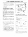
TO CHANGE ENGINE OIL (See Figs. t5 and t6}
Determine temperature range expected before oit change.
All oii must meet API service classification SF or SG.
Be sure tractor is on tevei surface.
o
Oil wil drain more freely when warm.
Catch oil in a suitable coniainer
Remove oil fin cap/dipstick. Be carefui no_to allow dirt
to enter the engine when chang ng oii.
_o, Remove drain plug
After oii has dra ned completely, replace oil drain ph_g
and tighten secureiy.
0
Refill engine wkh oil th:_ough ol fill dipstick tube. Pour
slowly. Do not overfill. For approximate capacity see
'PRODUCT SRECIF CATONS'
on page 3 of Ihis
ment/£i.
F_G°16
CLEAN
AiR SCREEN
(See Fig. 16)
Air screen must be kept free of dirt and chaff to prevent
engine damage from overheating. Clean with a wire brush
or compressed air to remove dirt and stubborn dried gum
fibers.
A_R F_LTER
(See Fig. 16)
Your ¢ngine will not run properly using a dirty air fitter.
Clean the foam pre-cleaner after every 25 hours of operation or eve_ season. Service paper cartridge every 100
hours of operation or every season, whichever occurs first.
Sen/ice air cieaner more often under dusty conditions.
,o Remove knob and cover.
,_ Remove wing nut and air cieaner from base.
TO SERVICE PRE-CLEANER
o
Stide foam pre-cieaner off cartridge.
Wash it n !iquid detergent and water.
Squeeze ii dr},'in a c!ean cioti_.
_0 Saturate it in engine oil.Wrap it in clean, absorbent
cioth and squeeze to remove excess oil.
TOSERVICECARTRIDGE
Gently_apthefiat sideof the papercartridgeto dis_oagedirt. Donot wasnthe papercannageor use
oressudzed _lr. as rots witl aamage the cartridge.
Replace a dirty, bent. or damagers ca_ridge.
Reinstall the pre_cleaner _cteaned and oiled1 aver the
paper cartridge.
Reasse mb!e air cleaner, wing nut. cover and tlgnten
knob securely.
CLEAN
AIR _NTAKK/COOLING
AREAS
To insure proper cooling, make sure the grass screen,
cooling finsl and other external Surfaces of the engine are
kept clean at all times_
Every' 100 hours of operation (more often under extremeIy
dusty, drty conditions), remove the blower housing and
other cooling shrouds. Clean the COOtingfins and extemai
surfaces as necessary. Make sure the cooling shrouds are
reinstaIled.
NOTE: Operating the engine with a blocked grass screen,
dirty or plugged Cooling fins, and/or Cooting shrouds removed will cause engine damace_'g
due to everheatJng,.
Inspect and replace corroded muffler and spark attester (if
equipped) as it could create a fi_e hazard and/or damage.
SPARKPLUGS
Replace spark plugs at the beginning of each mowing
season or after every 100 hours of operation, whichever
occurs first. Spark plug type and gap setting are shown in
"PRODUCT SPECIFICATIONS" on page 3 of this manual.
ENGINE
OiL FILTER
O_LFILTER
F_G_17
H-UNE
FUEL F_LTER
(S&e Fig, 18)
The fuel filter should be replaced once each Season. If fuel
filter becomes clogged, obstructing fuel flow to carburetor,
replacement is required.
o
With engine cooJ, remove filter and plug fuel line
sections.
o
Place new fuel filter in position infuel line with arrow
pointing towards carburetor.
Be sure there are no fuel line leaks and clamps are
properly positioned.
o
o
(See F:ig. 17}
Immediately wipe up any spilled gasoline.
CLAMP
CLAMP
Replace the engine oit filter every season or every other oit
change if the tractor is used more than 100 hours in one
year,
o
Drain oil from engine crankcase (See _%OCHANGE
ENGINE OIL" in this section of this manual, through
step remove drain piug).
o
Remove oil filter and wipe off filter adapter.
o
Apply a thin coating of new engine oit to the rubber
gasket on replacement oil fitter.
,
Install replacement oil filter on filter adapter. Turn oii
filter c!ockwise until rubber gasket contacts the filter
adapter, then tighten filter an addilionai 1/2 turn.
o
Fill crankcase with new oil (See "TO CHANGE EN-GINE OIL" in this section of this manual). For approximate capacity see "PRODUCT SPECIFICATIONS" on
page 3 of this manual
o
Start the engine and check for oit baksl Correct any
leaks before piacing engine into fuil operation.
FIG, 18
CLEANING
o
Clean engine_ battery, seat, finish, etc. of ait foreign
matter.
Keep finished surfaces and wheels free of at! gasoline,
oil, etc:
Protect painted surfaces with automotive type wax.
We do not recommend using a garden hose to clean your
tractor unJess the electricaJ system, muffler, air filter"and
carburetor are covered to keep water out. Water in engine
can result in a shortened engine life.
CAUTION:BEFOREPERFORMING
ANYSERVICE
ORADJUSTMENTS:
o
-
Oepress clutch/brake pedal fully and se_ parking brake.
P_ace motion contro_ _ever in neutra_ (N) position.
Place attachment clutch in "D_SENGAGED" position.
Turn ignition key "OFF" and remove key.
_,_ake sure the b_ades and all moving parts have completely atoppedo
©iscor_r_ect spark p_Jg w_re from spark p Eugann place wire where it ¢annct come in con[act
with _ !:_.
CLUTCH
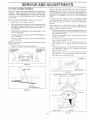
TO REMOVE
MOWER
RETAINER
SPR_NG
(See Fig, 19)
!lower wiil be easier to remove from the right side of tractor.
Place atlachment clutch m 'DISENGAGED" pos tion,
LEVER
CLUTCH
ENGINE
/PULLEY
Move attachment lift Iever forward to lower mower to its
lowest ooslt_on.
Rotl belt off ename oui!ey,
Disconnect clutch rod [rom clutch Iever by removing
re[amer spnng.
Disconnect anti-sway o_r Irom cnass_s bracket ey
remowng relamer spring,
Disconnect susoens_on arms from rear OeCKbrackets
Dy removing retainer springs,
Disconnect tront inks from deck r_y removfflg re_amer
sDnn(] S,
j.-
Raise lift lever to raise suspension arms. Slide mower
out ,from under trac[or,
Ri_POHTANT: IF AN ATTACHMENT OTHER THAN THE
ViOWER 1S TO BE MOUNTED TO THE TRACTOR THE
R,H AND L.H, SUSPENSION ARMS MUST BE REMCVED
ROM TRACTOR.
t°O _NSTALL
MOWER
(See Fig. t9}
Raise attachment lift lever to its highest position.
Slide mower under tractor with discharge guard to right
side of tractor,
Lower lift lever to its lowest position.
instal] mower in reverse order of removal instructions.
RETAINER
SPRING
ANTFSWAYBAR
RETAINER
SPRINGS
(BOTH SIDES;
FIG. 19
SE
TO LEVEL MOWER
HOUSING
FRONT-TO-BACK
Adjust the mower while tractor is parked on _eve_ground or
driveway.
Make sure tires are uropedy inflated See
'PRODUCT SPECIFICATIONS" on page 3 of this manuai),
ftires are over or undefinfiated,you witl not properly adjust
your mower,
SIDE-TO-SiDE
ADJUSTMENT
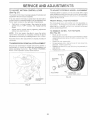
See Figs. 20 and 21"
Raise mower to its highest position
Atthe midpoint of both sides of mower, measure height
from bottom eage of mower_o grouna. Distance"A" on
both sides of mower _houid be the same or within _/_."
ot each other.
It adjustment is necessary, maKe adjustment on one
side of mower only.
To raise one sloe of mower tignzen lift link adjustment
nut on that side,
o
To lower one slde of mower ioosen lift link adjustment
nut on that sloe.
NOTE: Each full turn of adjustment nut will cnange mower
height abou! 1/8"
Recheck measurements
IMPORTANT:
MUST
(See Figs. 22 and 23)
BE LEVEL
S/DE-TO-SIDE.
Check _ulus[men] on Hgn_ s_ae of _racTor. Measure d_slance 'D" directly _ntrent and behind the mandrel at bottom
eage of mower nousmc_ as shown.
,
Before making any necessary adjustments, checkthat
seth trent Nnksare ecual in iengtho Both links shoulo be
approximately 10-3/8"
tf links are nor equal ir e_ _th adjust one Nnkto same
Iengl:h as other/ink.
To lower trent ot mowe_ _oosen nut "E'" on both front
nKS an eoua_ number o_,_urns
o When distance 'D" is _iz _:o3/4" lower a_ front than
rear. Rgn[en nuts "F" agams_ [runnlon on both front
linKS.
BOTTOM EDGE I
OF MOWER TO I
GROUND
o
To raisetrentot mower !oosennut"F" fromtrunnionon
both front Nnks. i-ig _te_: nut "E" or_ both _ronr ]inks an
eoua_ number ot turns
When d_star;ce "D" is _- [o 3/4' lower a[ front than
rear, tighten nut"F" against trunnion on both front links.
Recheck side4o-side adiustment.
FIG, 20
FIG 22
BOTH FRONT LINKS MUST BE &(:_UAL tN LENGTH
f. .....
LIFT LINK
ADJUSTMENT
IF
THE FOLLOWING FRONT-TO-BACK eDJUSTMEN q tS
NECESSARY BE SURETOADJUST BOTH FRONT LINKS
EQUALLY SO MOWER WiLL STAY LEVEL SIDE-TOSiDE
To obtain the best cutting results. IRe mower qouslng
should be adjusTea so that me rront _sa_orox_mately 1/4" to
3/4" lower than the "ear wnen rne mower s _n its hghes[
posit;on
after adjusting.
BOTTOM EDGE
OF MOWER TO
GROUND
ADJUSTMENT
DECK
NUT
FIG. 21
NUT "E"
FRONT UNKS
TRUNNION
F!G 23
F
TO REPLACE
MOWER
BLADE
WITH
DRIVE BELT
PARKING
BRAKE
"ENGAGED"
""-----"-'-_NUT "A"
(See Fig. 24)
1-3/4'_
_ d AM
NUT
The mower blade drive beit may oe reolaced without tools.
Park the tractor on level surface. Engage parking brake
BELT REMOVAL Remove mower trom tractor .See TO
MOWER" in this section of this manual).
REMOVE
Work belt off both rnanare_ pulleys and idler 3ufleys.
Putt belt away Tram mower
O_PERATING
ARM
BELT INSTALLATION.
{nst8 new belt r reverse oroer of removal.
o
Make sure belt is in at1putiey grooves and inside all bett
guides.
Ins[atl mower in reverse order of removal instructions.
/
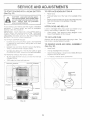
DO NOT TOUCH TBIS NUT, IF FURTHER BRAKE ADJUSTMENT IS NECESSARY CONTACT YOUR NEAREST AUTHORIZED SERVICE CENTER/DEPARTMENT
FIG. 25
MANDREL
PULLEY
WDLER
PULLEYS
TO REPLACE
f
MOTION
DRIVE BELT
Park the _rac_or on leve_ surface. Engage parking brake.
For assistance :nere s a bert _nstaHaflon guide decat on
bottom s_oe Dt left footres!
Remove mower _See "TC REMOVE MOWER" in this
see[Ion
MANDREL
PULLEY
FtG. 24
TO ADJUST
BRAKE
Of ,_nIs malquai.
o
Remove upper bett keeper.
o
Remove belt from stationary idler and clulching idler.
o
Puff belt slack toward rear of tractor. Carefully remove
belt upwards from transmission input pulley and over
cooiing fan blades.
Pull bett toward front of tractor and remove downward
from around engine pulley.
o
tnstai/new bett by reversing above procedure.
IMPORTANT: MAKE SURE UPPER BELT KEEPER fS
POSITIONED PROPERLY BETWEEN LOCATOR TABS,
(See Fig. 25}
Your tractor is equipped with an adjustable brake system
which is mounted on the side of the transaxle.
PULLEY
If tractor requires more than six (6) feet stopping distance
at high speed in highest gear, then brake must be adjusted.
IDLER
o
Depress ciutch/brake pedat and engage parking brake.
o
Measure distance between brake operating arm and
nut "A" on brake rod.
TABS
UPPER BELT
KEEPER
}DLER
tf distance is other than 1-3/4", loosen iam nut and turn
nut "A" until distance becomes 1-3/4% Retighten jam
nut against nut "A'_.
Road test tractor for proper stopping distance as stated
above. Readjust if necessary'. If stopping distance is
still greater than six (6) feet in highest gear, further
maintenance is necessary. Contact your nearest authonzed service center/depa_ment.
TRANSMISSION
INPUT PULLEY
F_G. 26
SE
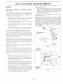
TO ADJUST
_OT_ON
CONTROL
LEVER
(See Fig, 27)
TO ADJUST
STEERING
_VHEE_ ALIGNMENT
The rnotion control lever nas been preset at the factory and
adjustment should not be necessary..
_fsteering wheel crossbafs are not horizontal (left to right)
when wheels are positioned straigiqt forward, remove steep
ing wheei and reassemble per nstructions n the Assembly
section of this rnant al.
!f for any reason the motion control fever wilt not hold its
position while at a selected speed, _ may be adjusted at the
friction pack located on the right side of transmission.
FRONT WHEEL
T_{SE--N!CAMBER
o
Park Iractor on level surface Stop _ractor by turning
ignition key to 'OFF' position and engage parking
brake.
The front wheel teeth and camber are not adjustable on
your tractor. If damage has occurred to affecl the front
wheel toe4n or camber contact your nearest authorized
service centeffdepa¢_ment,
o
Adjust motion control lever by lightening adiustment
IocRnut one half (I/2) turn.
TO REMOVE
NOTB: If for any reason the etfott to move the motion
controf Iever becomes too excessive reverse the above
aciiustment procedure by tooseni¢ 9 tecknut I/4 to l/2 turn,
Road test tractor after adjustment and repeat procedure if
necessary
TRANSB@SS_ON
FOR REPAIRS
(See Fig, 28}
o
Block up axle sec,dreiy.
Remove axle cover, retain ng rng and washers to ailow
wheel removei (rear w/ee! contains a square key .-Do
o
Repair tre and reassemble
On rear wheels only: align grooves in rear wheel hub
and axle. Insert squae key
Replace washers and snap retaining ring securety in
,o
Replace axlescover.
RE_aOVAUREPLACEMENT
Should your transmission require removal for sePdce or
replacement; it should be purged after reinstat_atJonand
before operating the tractor, See "PURGE TRANSMIS-SION" in the Operation section of this manual
WHEEL
/
F_G_ 28
ADJUST_tENT
LOCKNUT
FIG. 27
E
TO S _AR°__ _: tGINE
{See Fig. 29)
W_TH A 'WEAK BASWE_Y
ate explosive 9ases_ Keep sparks_ flame
and smoking materials away from bat_,
retie.so Always wea_ eye protection
whe_'_ a_o_snd batteries,
If your battery s too weak to start the engine, it should be
rectarged_
ff '_iurTper cables' are used for emerger£;y
starti_9
fo!low this procedt re:
t_PORtf'ANT:
YOUR TRACTOR
S EQUIPPED WF[HA
12 VOLT _EGA !_}VE GROUND!£D SYSTEM. THE OTHER
VEqiCLE
MUS!
ALSO
B[: A 12 VOLT NEGATWE
GROUNDED
SvST!f:M,
DO _,;Or #SE'{OUR
TRACTOR
BATTERY TO START OTHER VEHICLES
TO A°FTACH JLIMP{{{A CASLES ,,
o
_
Connect each end of the RED cable to the POSI7 VE
(+) terminal of eacis baltery, ta!,(i sg care not to short
against chassis.
Connect one _
af the BLACK cabe to the NEGA.TiVE (0 erm nai of fully char0ed battery,
Connect Ihe artier end of "_e SLACK cable to good
CHASS S GROUND away fro_ ftei tank and battery
iTO REPLACE
BLACK cabie f_st from chass s _{_Rd
then fore the £iy
charged battery,
RED cable last from both baiteries,
POSITWE _'ERM1NAL
t_::._A W_:
8aise hood,
o
Pull bulb holder out of the hole in the backside d the
9rilt.
o
Replace bulb in holder and push bulb holde_ securely
back into the hole in the backside of the g_iI[
C!ose hood.
o
INTERLOCKS
ANO RELAYS
Loose or damaged wiring may cause your tracior !o run
pooriy stop running, or prevent it from starting,
o
TO
Check wiring. See electrical wiring diagram in the
Repair Parts section of this manual.
REPLACE
FUSB
Replace with30 amidautomotive-lype
plug-in
fi_se,
The
fuseholderislocated
behindthe dash.
TO RE_IOVE HOOD AND GRIL_ ASSEMBLY
(See F!g_SO}
Raise hood
o
Unsnap headlight wire connee_or_
o
Stand in iront of tractor_ Grasp hood __4t
sides, [i{t [award
engine a_d lift off of tracto_
,_
7o reptace,
reverse above procedures.
ROOD
ERbIINAL
x •
/
/
/
xL,_f
/
'\
/
HEADLIGHT
WIRE
CONNECTOR
FIG. 30
F!Go 29
BULB
,0
TO Rr4MOVE CABL££S RE'i(:RS_} ORDER
._
HEADUGHT
ACCELERATION
TO ADJU87'
3"HROT?tJ£
COE_T::_OL CABLE
(See Fig 81}
The throttie con<rol has been preset at the factory and
adiustment should not be necessa% Check adiustment as
described beiow before _oosening cabie, If adjustrnent is
necessa% proceed as fo{ ows
_,
\/,,!i_hengi_e not runn ng, move tbrottie control !ever
from siow (<@,) to choke (b,i} p:;sition. Slowly move
lever from choke {N) to fast (_@)pos rich.
Check: to see if hob in tn 'otde iever and hole in speed
contrel brac_tet are aligned,
If !oes are sot aiigned, loosen cable clamp screw and
a!ign the hoies by nsett _'g ape _cii or a !/4" driI! bit
through bo_h hotes_
Move throttle control lever from slow (_)
to fast
position.
If engine hesitates or dies, turn idle
adjusting needle out (counterciockw
se) i/8 turn.
peat test and continue to adjust, if necessary,
engine accelerates smoothly.
CABLE
CLAMP
,,Xq (See Fig. 82}
me_t may be required to compensate fo differences in fuei,
temperature, altitude ot cad. !f the c_rburetor does need
adiust,'_ent proceed as foltows:
in general tur_ng the adjust ng _eedies i_ (clockwise}
dec:eases the s_ppty o[ fuei to _:_ee_ sine giving e leaner
fueiia r mixture. Turning the adjusting needles out {counterclockwise) increases the s_ppy of uel to the engine giving
a fiche fuei/air mixture.
IMP{),_A_*{
O[1:,_©
,
DAMAGC
O_[: B,_,
p_
%7m
0 / "h NEEDLES AI L THE
bE©J*_
.
TURNED N TOOTIGHi'.
5JOT[: The carburetor or this engi_e is low emission, it is
equ@ped wt! _ a_ idJe uel sd]_sting i'eed/e with a ihTfiter
cap wi ie_ allows some djus mer_ v,,tt ia the imitsailowed
by the cap. Do not atternp_ to remove the }imiter cap. The
iimiter cap cannot be _'en,eyed without b eaking the adjusting
nee:! e
_DLE SPEED
ADJUSTING
Be sure you have a ciear ar filter and the throttle
control cable is adjusted p opedy {see above).
o
Sta£ engine and allow to warm fer five minutes. Make
adiustments with engne running and sh.ift/motioncontro!
lever n neutral (N} position.
i;_
i}%; - With tb'otde cont_'oi lever in slow
(,_)
position, engine shouid die at 1750 RPM, !f
engine idles too slow or fast, turn idle speed adjusting
screw n or out untit correct idle is attained.
°
_:!£_4<_._1_i!!£5A_£it]:g With throttle contro! lever n
siow (_} position, turn idle fueI adjustment needle i_
(clockwise) untii engine begins to die and then turn out
(ce_or te_ciockwise) until engine HJnS rough. Turn needle
to a point n alway between those two positions.
_:, Recheck die speed
Readius if _ecessa_<
(@)
fuet
Reuntil
High speed stop s factoR__ adjusted.
Do not adjust ..
damage may result
_[_ORTAN'T:
NEVER TAMPER
WITH '['HE ENGINE
GOVERNOR,
WHICH IS FACTORY SET FOR PROPER
ENGINE SPEED. OVERSPEEDINGTHE
ENGINE ABOVE
THE
FACTORY
HIGH
SPEED
SETTING
CAN
BE
DANGEROUS
iF YOU THtNK THE ENGINE°GOVERNED
HIGH SPEED NEEDS ADJUSTING!
CONTACT
YOUR
NEAREST
AUTHORIZED
SERVICE
CENTER/
DEPARTMENT,
WHICH HAS PROPER BQWPMENT
AND
EXPERIENCE
TO
MAKE
ANY
NECESSARY
ADJUSTMENTS.
_0 Pull throttle cable up to remove slack and tighten cable
clap screw, Remove a gnment pencil or @1Ifbit
,.,ARBU
TEST
ADJUSTING
NEEDLE
FIGo 32
Immediately prepare your tractor for storage at the end of
the season or f the tractor will not be used for 30 days or
mo re.
i_YaPORTANY:
iT iS _MPORTANT TO PREVEWT
GUM
DEPOSTS
FROM FORMING
iN ESSENTIAL
FUEL
SYSTEM PARTS SUCH AS CARBURETOR,
FUEL FILTER,
FUEl_. HOSE, OR TANK DURING STORAGE.
ALSO,
EXPERIENCE
INDICATES
]HAT ALCOHOL
BLENDED
FUELS (CALLED GASOROL
OR USING ETHANOL
OR
METHANOL
OAN ATTRACT MOISTURE WHICH LEADS
TO SEPARAT ON AND FORMATION
OF AC1DS DUR!NG
STORAGE
ACIDIC GAS CAN DAMAGE
THE FUEL
SYSFEM OF AN ENGINE WHEE IN STORAGE.
Remeve mower fror_ tractor for winter storage. When
mower is to be stored for a period of time, ,dean t thoF
oughty, remove ail dr% grease, eaves, etc. Store in a
clean, dry area..
o
Clean entire tractor (See ';CLEANING '_in the Customer
Responsibiliiies section of this manuai).
Inspect and replace belts, if necessary (See belt re.
placement instructions in the Service and Adjustments
section of ths manual)
Lubricate as showfi in tlie Custom@: Responsibiiities
section of this manual
'_
Be sure that a!t ntsts, boils and screws are sec_rei_,
fastened_ InspeP:: moving pa_s fo_ damage, breakage
and wear Repace if necessa%
o
Touch up ai nJsted or chipped part
ight!y before pair ting.
_
D"ain the fuei tank.
_
SIart the engine and let it run until ihe iuel lines and
carburetor are empty
o
Never use engine or carburetor cleaner products in the
Iue tank or permanent damage may occur.
Use fresh rue} next season.
NOTE:
Fuel stabiizer is an acceptable altemaive
in
minimizing the font ation of fuel gum deposits during stof
age Add stabilizer to gasoline in rue! tank or storage
conta ne Always follow the mix ratio found on stabilizer
conta her. Run engne at least 10 minutes alter adding
stabilizer to a/ow the stabifizer io reach he carburetor. Do
not drain the gas tank and carburetor if using fuel stabilizer.
....... ¢:{_,
stJd_aces; sand
o
FuJiy charge the battery for storage.
_
After a pared of time in storage battery may require
Drain oi! (with eng re warm} and replace with clean engine
oi!
e :_ 'ENGINE' _n the Customer Responsibilities
-oe_:,
section of this "nanua!},
_-_
"_ To help prevent corresion and power leakage during
long perods of storage, batten/ cables should be
disconnected and battery c%aned thoroughly (see "TO
CLEAN BATTERY AND TERMINALS" in the Customer' Responsibilities section of this manual).
_,
_,
emove ,: pa, k p/gs)
:'our one ounce of .'.)iimrogh
spark plug hole(s) inio
Turn iarfition_key,to "START" position for a few seconds
,'s+ r i b,_t.,
t ¢_ oi.
o dk_,
¢
Replace with new spark plug(s).
After cleaning, ieave cabtes disconnected and piace
cabies where they cannot come in contact with batted/
terminals
'_
Be sure battery drain _ube is securely attached.
o
Do not store gasoline from one season to another
_
!f batteg, is remevtd from tractor for storage, do not
store batter}' direcIly on concrete or damp st_ffaces
'o
Replace your gasoline can if your can starts to rust.
ru:_t ,:.n@or dirt n your gasoline will cause p robtnrn<
....
tf possible sto_e your trac!or indoors and cover it to
give protection from dust and dirt.
_o Cover your tractor with a suitable protective cover that
does not retain moisture. Do not use plastic. Plastic
cannot breathe which allows condensation to form and
wit cause your t_'actor to hist.
_,_POR_FANT: NEVER COVER TRACTOR WHILE ENGINE
AND EXHAUST AREAS ARE STH._LWARM
PROBLEMS
W_H not sta_
CORRECTION
CAUSE
I
Out of fuel.
1.
Fill fuet tank.
2.
3.
4.
5.
6.
7.
Engine not "CHOKED" propedy.
Engine flooded.
Bad spark plug.
Didy sir filter.
Diriy fuel fiker.
Water in fuel.
2.
3.
4.
5.
6.
7.
8
9
10.
Loose or damaged wiring,
Carburetor out of adiustment.
Engine valves out of adjustment.
8.
9.
10.
See 'TO START ENGINE" in Operation section.
Wait severai minutes before attempting to start
Rspiace spar}< plug.
Cleanirepiace air fitter.
Replace fusi filten
Drain fueI tank and carburetor refiJi_enk with fresh
gasoiine and repiace fuel fitter.
Check aft wiring.
Contact an a_ithorized service center!department.
Contact an authorized service center/department.
Nard to start
i.
2.
3.
4.
5.
6.
7,
8.
Dirt},air filter,
Bad spa_k plug.
Weak or dead baden/
Dirty fuel filter.
Stale or dirty fuel.
Loosear damaged wiring.
Carburetor out of sdiustment.
Engine valves out of adjustment.
t
2.
3.
4.
5.
6.
7.
8
Clean/t'ep_eee air fi!ter.
Repiace spark plug.
Recharge or replace battery.
Replace faei fiiter
Drain fuel tank and refil with fresh gasoline.
Check aii wiring.
Contact an authorized se[vice centeddepartment
Contact an authodzed service center!department.
Engine
i.
2_
3.
Clutch/brake pedatnot depressed.
Attachment clutch s engaged.
Weak or dead bailer%
4.
%own
5.
6.
7,
8
9.
Corraded battery terminels
Loose sr damaged wiring.
Fau_fli ignition switch.
Faulty solenoid or starter.
Faulty operator presence swi_ch(ss)_
1,
2.
3.
4
5.
6
7.
8
9.
Depress ciutcb!bsake pedal
Disengage a/_tashment clutch.
!Recharge or repiace batte%
Replace fuse_
Clean bakery terminals.
Check all wiring.
CbecWrepiace ignition switoh.
ChecWrepiace selene d or star_er.
Contact an authorzed service center/department.
1,
2.
3.
4.
Weak or deaci battery.
Corroded battery terminals
Lease or damaged widn¢_.
Fauify solenoid or starter
I.
2.
3
4.
Ree _arge or replace batten:/.
Clean battery terminas.
Check aJiwiring.
CheeWreplace soleloid or s'_artec
1
2.
3.
4.
5.
6.
7.
8.
g
Set in 'Higher Cut" position/reduce speed.
Adiust throttle control.
Clears underside of mower housing.
Cben/reptace sir filtel.
Checkoii level/change oii.
Clean and regap or change spark plug.
Replace fuel filter.
Drain fuel tank and refill with fresh gasoline.
Dran fuei tank and carburetor, refil tank with fresh
gasoline and repiace fuel filter.
Connect and tighten spark plug wire.
Clean engine air screen/fins.
Clean/replace muffler.
Check all wiring.
Contact an authorized service centsr/department
Contact an aathodzed service ceetsddepartment
Engine
start
will not turn over
cllcks
but will not
Loss of power
I.
Cutting too much grass/too fast,
2. Throttle in "CHOKE _'position.
3.
Buib.ap of grass, ieaves and trash under mower,
4.
Dirty air filter.
5. Low oil level/dirh/oil
6_ Faulty spark piug.
7. Dirty fuel filter.
8. Stae or dirty fuel.
9. Water in fuel.
10.
!1.
12.
13.
14.
15.
_
4
Excessive
vibretfan
fuss,
Span< plug wire loose.
Dhly engine air screen/fins.
Dirty/ctogged muffler.
Loose or damaged wiring.
Carburetor out of adjustment.
Engine valves out of adiustment.
1.
2.
Worn, bent or loose blade
Bent blade mandreI.
3,
Lease/damaged
part(s)_
10.
11.
12.
13.
I4
15
1.
2
3.
Repiace blade. Tighten biade bert.
Replace blade mandrel.
Tighten loose part(sL Replace damaged parts
NG
P_©Bk_'I
CAUSE
CORRECTION
Engine aentinues to rar'_ t 1_ Faulty oporak}r-safoty
when operate_ _eaves seat
with attsehmer_t clutch
1
Poor cut -_a.*_,even
presence control system.
i,
Ci_eck wiring, swtches and connections.
If not
corrected, contact an authorized se_,°vicecenter/
department.
1.
2.
Worn, bent or loose Made.
Mower deck not level.
1.
2,
Replace b_ade. Tighte"_blade boiL
Levei mower deck.
3,
4.
Buildup ef grass,/eaves,
Bent blade mandrel.
5,
Clogged mower deck ven_ holes from buildup of
grass, leaves, and irash around mandrels,
3.
4,
5.
Clean undersidoef mower housing,
Replace blade mandrel
Clean around _andre;s te open vent holes.
_4ewsr blades will r'tot
!,
Obsbuction
1.
Remove obstr_Jctioa,
relate
2.
3,
4.
Worn/damaged mower drive belt.
7rozenidler pulley,
/::'rezen blade mandrel,
2,
3,
4.
Replace mower drive _-_e/t.
Repiaca id!e¢ pa!loy.
Repiaeo bletSomandra.
Peer grass discharge
1
2
3,
4.
Engine speed toe slew,
'Trivet sp_ed too fast:
Wet grass.
Mower deck net/evoL
/.
2:
3.
4.
Shift to slewe_ speed;
Allow grass Io dr}, betc,_omewing.
Level mowe_ deck.
5
6
Lewiuneve_t tire sir pressure:
Worn, bent or loose bade,
5.
6.
7_
8.
9,
Check ires fc_ groper sir pressure.
Replace/sha,*#en b_ade_Tighten blade bok.
Clean underside of m{swer housin 9,
Replace mower drive be_t,
Reinstail blades sharp edge down
1] 0.
,/,
Reptace with b_ades listed in this n_anust.
Clean around mandrels to open verst tsoies.
7
8,
9,
10
1 I.
and trash under mower.
in clutch mechanism.
Bui du? of grass, teaves and trash under rnower.
Mower (rive belt were
Blades mprepefiy installed.
improper blades used,
Clogged mower deck vent holes from buildup of
g_ass leaves, and trash around mand_'eis.
1.
Switch is i'OFF',
.
Turn switch "ON",
2,
3.
4.
5.
Bt,gb(s} bumad out,
Faulty fight switch.
Loess or damaged wit}no.
Blown fuse.
2.
3,
Replace balboa},
Check,'rep!aee_ght
4
5
Chec_ wiring _a
Repleca fuse.
I.
2.
3.
4.
Bad battep}, cett(s),
Peer cable connections.
Faults/regulator (if so eqapped).
Faulty alternator,
I.
2.
Replace batta_'!f
ChecWcear_tconnections,
3
4.
Replace regal;star
Reelece a_tereater.
Less o_ drive
1.
2
3.
Freewheel control in 'disengaged" position.
Motion drive bel_ worn, damaged, or broken.
Air trapped in transmission during shipment
or sewicing.
I.
2,
3.
Place freewhee_ centre in 'engaged" position.
Replace mot2,_drive belt.
Purge [ransmissien.
Engine "backfires"
when tumin 9 engine
'OPF"
1
Engine throttle centrol not set at "SLOW"
position for 30 seconds before stopping engine,
i.
Meve throttle cen[rel lo "SLOW" pesitien and allow
to ide for 30 seconds before stepping engine.
Headlight(s} _ot werkir!g
(if so equipped}
Battery
wH _ot charge
sw_lch.
con_ections.
TRACTOR
o - MODEL
NUMBER
917o256552
RED
BLACK
BATTERY
AMMETER
-----
r-Sil_
_
RED
FUSE 30 AMP,
I
STARTER
BLACK
CLUTCH / BRAKE
(PEDAL UP)
.......
X
.......
SEAT
i
i
] !GN_TION
i SWITCH
J
!
J
]
SW!TCH
(NOT OCC _PIED)
!
I
}
iI
,
BLACK
i
ATTACHMENT
CLUTCH
BLACK
i
iGNITION
GROUNDING
_ONNECTJR
..........
.........................
_N!':
................
!
,
SPANK
_÷
PLUG @ ..........
F',_
\)
I
BlUE
I
28 VOLTS AC M_N. @ 3600 RPM
{CHARGING SYSrEM
D}SCONNEC
/
rED}
j .....................
RED
ORANGE
" 14 VOL:B
........_--
NON-REMOVABLE
CONNECTIONS
..........
t..j-- .... REMOVABLE
CONNECTIONo
IGNITION SWITCH
[ POSmON I C_RCUn_[ "_AAKE"
L i
NONE
A+Y
l
[
RUN i _÷1., I NONE
START
iB+L+S
!
NONE
WIRING _NSULATED CLIPS
NOTE: iF WIRING INSULATED
CLIPS WERE REMOVED FOR
SERVICING OF UNIT, THEY
SHOULD BE REP[ACED TO
PROPERLY SECURE "fOUR
WIRING
AC M[N
@ 3800 RPM (L GHTS
OFF)
"__.1) HEADLIGHTS
NOT_
YOUR TRACTOR IS EQUIPPED WITH
A SPECIAL ALTERNATOR SYSTEM.
/_7-/
THE LIGHTS ARE NOT CONNECTED
TO THE BATTERY, BUT HAVE THEIR
OWN ELECTRICAL SOURCE.
BECAUSE OF THIS, THE BRIGHTNESS
OF THE L!GHTS WILL CHANGE VVITH
ENGINE SPEED. AT IDLE THE LIGHTS
WILL DIM_ AS [RE ENGINE IS
SPEEDED UP, ]RE LIGHTS WILL
BECOME THEIR BRIGHTEST_
REPAIR PARTS
TRACTOR
oo _ODEL
NU_o_BER 917_256552
22
21
4O
26
19
20
25
/
S9
/
/
3S
/
/
45
29
52
15
\
REPAIR PARTS
TRACTOR
KEY
NO.
o o MODEL
PART
NO_
I
2
3
4
6
7
8
9
15
I8
19
20
21
146140
74760412
STD551025
STD551125
STD541025
109238X
144940
I09596X
147688
153664
STD55!125
73350400
147430
22
24
4152J
4799J
25
146147
26
28
29
30
31
32
33
36
38
39
40
41
42
43
44
45
52
70
108824X
4207'J
t21305X
140301
124211X
141226
109310X
STD601005
140336
I09553X
151212
71110408
131563
145673
73640400
!_14ooX
141940
142291
NOTE:
NUMBER
917.256552
DESCRiPTiON
Battery !2 Volt 30 Amp
Be/t, Hex Head !/4-20 uric x 3/4
Washer
Washer
Nut
Tube, Plastic, !2"
Case, Batter'/Wi2 He!es WiBrty
Clamp, Hose
Switch tntedock Pushqn
Washer, Lock
Nut, Hex, Jam 1/4-.20 UNC
Harness, Ligh[ Socket
(Includes 4152J)
Bu!b; L!g!st
....................................................................................................
Cable, Batter% 6 Gauge, Red, !i"
Cabfe, Batteqh 6 Gauge, F_d, W/
!6 Wir
Fuse, 30 Amp
Cable, Ground, 6 Gauge, Black, 12"
Switch, P!unger
Switch, Ignition
Nut, Ignition
Cover, Key Switch
Key, Ignition
Screw
Bracket, Inter!ock Switch
Switch, tnte,qock, Clutch, 4 Terminat
Harness, Ignition
Bolt, Hex Head, Fin. 1/4_20 x I/2
Cover, Termina, Red
Solenoid
Nut Keps Blk Hex 1/4-20 UNC
Ammeter Rectangular 6 Amp
Protection Wire Loop (Hour Meter)
Harness Engine Kohl Cmd. t
All component dimensions given in U_S. inches
1 inch = 25.4 mm
EPAIR
PARTS
TRAOTOR
CNASStS
- - MODEL, NUB4BER gl 7,,256652
AND _NCLOSURE_
28
25
26
12
25
26
53
52
55
14
t5 ....
_,)<;-,
.
-3
54
4O
\
'
!
33
10
14
REPAmR PARTS
TRACTOR
CHASSIS
o o MODEL
NUMBER
917o256552
AND ENCLOSURES
KEY
NO.
1
2
3
4
5
6
8
9
10
!1
t2
13
14
I5
PART
NO.
151169
140356
17490612
19I31216
146077
145206
126471X
147633X010
72140608
146956
145660
146962
17490608
74180512
i6
STD64s43s
i7
t44985X658
24 STD5237!0
25 19131312
26 STD541437
28 145198X558
29 145199
30 1473t0X558
3t
139976
33 145244X558
34 I45243X558
35 STD533707
38 139886
39 139887
4O 139977
51 738OO4OO
52 19091416
53 145201
54 I7030814
55 145202
57 74780412
58 150127
60
74 STD541437
t40 150556
°- 5479J
DESCRIPTION
Drawbar
Screw, Thd. Roll. 3/816 x 3/4
Washer 13/32 x 3/4 x 16 Gauge
Bumper Snapqn
Saddle
Clip _nsulator .406 Mt9 Hole
Dash
Bolt, Caniage 3/8q6 x 3/4
Panei, Dash_ L.H.
Clip Tinnerman Grille P/L
Panet, Dash, R.H.
Screw Thdrot 3/8o16 x 1/2
Serew_ Maehine_ T_uss Head
5/16-!8 UNC x 3/4
Nut
Bolt
Washer -13/32 x t3/16 x 12 Gauge
Grill
Lens_ Gritle
Fender
Bracs(et, Fender Support
Footrest, L.H.
Footrest, R.H.
Bolt
Pivot Bracket Assembly, L.H,
Pivo Bracket Asse'_biy, R.H.
Spacer Pender Raised LT
Nut Lock, w!Insert I/4o20 Unc
Washer 9/32 x 7/8 x 16 Ga.
Bracket Gritie Pickoff Lh
Screw Spidedock Hex Hd #8o7/8
Bracket Gdlle Pickoff Rh
Bo_t 5n Rex 1/4-20 Uric x .75
Duct Air Engine PiL Lt
Bolt Rdhd Sqnk 3/8-.16 UNC x 3/4
Nut, C_ownbck 3/8-16 UNC
Bracket Chassis Front 7 Ga.
Plug, Button
NOTE: Aii component d[mens'_ons given in US. inches
1 inch = 25.4 mm
REPAR PARTS
TRACTOR
° - _ODBL
57
NUMBER
917.256552
19
42
7O
"116
.......86
I
3
',- 2':-:s
\
.;>.jj_
87
21
45
42
44
35
48
97
36
45
46
I9
18
16
32
53
96
95
73
30
!6
104
55
77
106
I05
I O0
71
78
REPAIR PARTS
TRACTOR
KEY
NO_
PART
NOo
I
2
3
8
10
15
16
18
19
2t
22
24
25
26
27
28
29
30
31
32
34
35
36
37
38
39
40
41
42
44
45
46
47
48
49
50
51
52
53
55
56
57
150071
142431
!43995
141003
76020416
74490544
73800500
74.780616
73800600
130564
145627
73350600
106888X
19131316
76020412
t45204
124236X
130807
12727{iX
747605s2
151128
i20i83X
19211616
i572H
t23674X
74760644
4470J
153399
i91313t2
I05706X
1i0812X
12000039
127783
123789X
123205)(
74760624
73680600
73680500
I05710X
I05709X
74760620
140294
o o MODEL NUMBER
DESCRIPTION
Transaxie Assembly
Sprin% Return, Brake
Pulley_Transaxte
Rod Shift Hydro LT
Pin Cotter i/8 x 1 CAD
Bott Hex Flghd 5/16-I8 Gr. 5
Nut Lock Hex Wlins. 5/16o!8 Unc
Boit Fin Hex 3/8-16 Uric x 1 Gr. 5
Nut Lock Hex W,ANsh 3/8 _.16Unc
Knob, Detuxe 1/2.-13
Rod, Brake Hydro
Nut, Hex Jam 3/8-16 Unc
Spring, Brake Rod
Washer
Pir_ Cotter t/8 x 3/4 CAD.
Rod; Parking Brake
Cap Parking Brake
Bracke:_,Transaxfe
Keeper Belt Lh
Bo/tHexHd
5/16°!8Unc×,%4
Shaft Foot Peds_
Bearir,,g, Nyion
Washer
Pit, Roll
PJliey_ _dter, Flat
Bolt
Space_, SpIit
Keeper, Beit Retainer
Washer !3/32 x 13/16 x 12 Gauge
Bearing, Nylon
Washe_, Harder_ed
Rng, Klip
Pultey_ Idler, V.Groove
Betlcrank Assembiy
Retainer, Belt
Belt
Nut Crownlock 3/8-!6 UNC
Nut, Crownlock 5/16_18 Unc
Link, C_utch
Spring Return, C_utch
Bolt Hex 3/8o16 x 1-t/4
V.-Bett Ground Drive
KEY
NOo
917o256552
PART
NO.
59 140312
6t
17490612
62 8883R
63 140186
64 71170764
85 10040700
66 153400
69 142432
70 t34683
71 140158
72 19132012
73 140157
74 121199X
75 12t749X
76 12000001
77 i 23583X
78 121748X
81 140154
82 I23782X
83 19171216
84 140548
86 71208
87 I92120t6
88 12O00OO8
89 151147
91 7478O536
92 74780524
93 142564
94 140462
95 144643
96 4497H
97' 140469
98 73510600
100 19111216
102 141322
103 73940800
104. 1_0t56
105 71070516
I06 74780520
1!6 72110810
DESC_tPT_ON
Keeper, Center Span
Screw Thdro/. 3/8-16 x 3/4 Ty. TT
Cover, Pedal
PuJtey, Engine
Bolt Hex 7/16o20 X 4 Gr. 5
Washer
Keeper Belt Engine
Screw
Keeper Bolt Engine
Strap Torque Lh Hydro 18/20" T
Washer 13/32 x 1-I/4 x t2 Gauge
Strap Torque Rh Hydro 18/20" T
Spacer, Split
Washer 25/32 x 1-.1/4 x 16 Gauge
Key, Square .............................................
Washe_ 25/32 x 1-5/8 x 16 Gauge
Shaft Asm_ Cross Hydro 20" Tires
Spl'ing T_'_rsion T/A
Washer I7/32 x 3/4 x !6 Ga.
Rod, Tie Hyd_'o 20" Tires
Bushing Rod Strig. 829/632 ID
Washer 21/32 x !.-l/4 x 16 Ga.
Ring Klip #5304-62
Cor'_sole, Shift
Bolt Fin F!ex 5/I6-!8 x 2-I/4
Bolt Fir_.Hex 5/6-I8 Unc x I-.t/;2
Line Fuel Hydro 4"
Fan, Hydro 7"
Control Bypass Hydro 20" T',res
Retainer Spring 1" Zinc/Cad
Keeper Bolt Rh Hydro 0750. 18/20"
Nut Keps Hex 3/8q8 Unc
Washer 1 !/32 x 3/4 x 16 Ga.
Washer Bellville .501D x 1.50D
Nut Hex Jam Topiock I/4_.20 Unf
Arm, Contro Hydro
c_crew Cap Hex 5/!6 x 18 x 1
Bolt Fin Hex 5/16-18 Unc x t-.1/4
Bolt, Rdhd Sqnk 3/8.-16 x 1.25
NOT[_: All component dimensions given in U.S. inches
I inch = 25.4 mm
REPAIR PARTS
TRACTOR
STEERING
o o MODEL NUf_,ilBER 917.256552
ASSEMBLY
k
, .... [ ............ 38
\
_
-
',
//
"......... 42
47
t4
\
82
13
\
46
i ilfJ_:'
15
</f
3
/
f
_
/-4
,.J
+10
30
£EPA R PARTS
TRACTOR
STEERING
o o MODEL NUMBER
9t7o256552
ASSEMBLY
_'(EY
NO,
PART
NO.
1
2
3
4
5
6
7
8
9
10
1!
12
13
14
15
t6
121472X
142033
135227
135228
6266H
121748X
19272016
12000029
3366R
13O468
STD551t37
7361O6O0
110438X
7401!056
73901000
132624
!8
!9
20
21
22
23
24
25
26
27
28
29
30
32
36
37
38
39
41
42
43
44
46
47
51
54.
62
63
5707s
1240357
t26684X
STD551125
71100410
127501
109816X
124036X
I2684.7X
136874
19131416
17490612
STD561210
130.465
132196
152927
I26805X
19133808
t00711L
145054
121749X
153720
t21232X
6855M
73800500
74780520
149686
STD5237!0
NOTE:
DESCRIPTION
Front Axle Assembly
Spindle Assembly, L.H.
Spindle Assembly, R.H.
Bearing, Race, Thrust, Hardened
Washer 25/32 x 1o5/8 x 16 Gauge
Washer 27/32 ;.' 1-1/4x 16 Gauge
Ring, Klip
Bearing, Steering Column
Link, Drag
Wasiler, Lock
Nut, Hex, Firs. 3/8-24 UNF
Spacer, Bearing, Front Axle
Bolt, Hex Head 5/8tl
UNC x 3-1/2
Nut, Lock, Fiange 5/8..11 UNC
Pin, Axle 5/8 x _.55/1.54
Shaft Assembly Steering
Hasher, Thrust .515 x 750 x .033
Supped, Shaft
Washer' Shim I/4 x 5/8 x .062
Washer
Screw Cap Socket Head Phos & Oil
Pittrr_an Shaft Assembly
Nyiiner_ Snapqn
Brackel, Steering
Bushing, Link_ Drag
Gear, Sector'
Washer 13/32 x 7/8 x 16 Gauge
Screw, Thd. Roll. 3/8-I6 x 3/4
Pin
Bushing, Steering
Screw TT #10--32.5 x 3/8 Flange
tnser!, Steering Wheei
Washer i3/32 x 2-3/8 x 8 Gauge
Adaptor, Steering Wheel
Boot, Steering Dasis P!L Mt! BIk
Washer 25/32 x !_1/4 x 16 Gauge
Extension Shaft Steering NomAdjust
Cap, Spindle
Fitting, Grease
Nut Lock Hx w/Ins. 5/16_I8 Unc
Bolt Fin Hex 5/18-18 Unc x i-I/4
Kit, Steering Assert #iy, Sewice
Bolt Fin He;;_ 3/8ot6 UNC x t Gr. 5
Atl component dimensions given in U.S. inches
I inch = 25.4 mm
REPAIR PARTS
TRACTOR
o o MODEL NU BER 917o256552
_0
if ........
6
22
J
\
5
f,Z-:?P
L
/
*>
25
23
12
KEY
NO,
PART
NOo
t
2
3
4
5
6
7
8
9
10
!2
I3
14
140123
140551
STD523710
I9131610
145006
STD541437
I24181X
17490616
19131614
140552
12i246X
i21248X
7205041!
DESCRiPTiON
Seat
Bracke_ Pivot, Seat
Bolt
Washer 13/32 x 1 x !0 Gauge
Clip, Pushofn Hinged
Nut
Spring, Seat
Screw, Thd, Roll. 3/8q 6 × !
Washer 13/82 x I x I4 Gauge
Pan, Seat
Bracket, Switch Mounting
Bushing, Snap
Bolt, Carriage 1/4-20 × i.-3/8
KEY
NO.
PART
NO.
15 _134.300
16 121250X
I7
123976X
21 153236
22 STD54143t
23 74780814
24
25
26
19171912
127018X
STD551150
DESCRIPTION
Spacer, Sptit .28 x .88
Spring
Locknut, Flange 1/4 Grade 5
Bolt, Shoulder 5/16o18 UNC
Nut
Bolt, Hex Heed, Fin.
I/2-.13 x 7/8 Grade 5
Washer 17//32 x 1--3/16 x I2 Gauge
Bott, Shouider 5/16-I8 × 62
NOTE: All component dimensions given in U.S. inches
I inch =: 25.4. mm
REPAIR PARTS
TRACTOR
20
22
6
3
18
MO©EL
NUMBER
7
917,256552
7.
!8
16
10
!3
8
1t
12
13
21
t5
14
17
KEY
NO.
I
2
3
4
5
8
7
8
9
10
t!
12
I3
14
PART
NOo
140819
1499i8
151299
151300
142341
133644
1494O7
t5_o0_
146709
137537
4900J
146046
147138
136832
WHEELS
KEY
NOo
DESCR[PTfON
Decal,
Decal,
Decal,
Decat,
Decal,
Decat,
Decal,
Deca;,
Decai,
Decal,
Decal,
Decal,
Decal;
Decal,
Operating bsstruction
Fend Auto Trans Srs Gold
Hood, R,H,
Hood, L.H,
Drawbar Cntri Mvt Hyd Lt
Customer Maintenance
Side Panel Kohler
Mower, EZ3
Fenders Craftsman
Caution, English
Clutch!Brake E{ngiish
V_.Belt Drive Schematic
Chassis, 42"
VoBeJt Schematic
15
I6
17
18
19
20
21
22
23
--•
-,--
KEY
NO,,
& T_RES
4,10
/
PART
NO°
145245
142938
133179
15_30!
150333
t48710
138047
138040
149516
145247
!38311
_53955
153958
PART
NO
1
'2
3
4
59Xi2
85139
106222X
59904
5
6
7
8
9
!0
106732X427
278H
9040H
106108X427
122082X
7152J
11
oo
104757X
144334
DESCRiPTiON
Pad Footrest Rbr Sq Oraltsman
Decal Sdl Cold Sta£ Hydro !t
Decai, Mower' QC System
Decai, Ins. Hood 15HP O4V Polo
Decal Cap Cnsmr Hetp Line Srs
Decal tnser!. Strg Std Auto USA
Deca Battery Diehard Sears
Decai, Pane/Side Diehard Sears
Decal, Battery OangrfPsn Srs. Eng
Fastener, Pop !n Footrest
Decat, Lift Handle
Owner's Manual, English
OwnePs Manuat, Spanish
DESCRiPTiON
Valve Cap, Tire
Stem, Valve
Tire, Front
Tube, Front Tire
(Not Provided, Service item Only)
Rim, Front
Fitting, Grease (Front Wheel Only)
Bearing, Flange (Front Wheel Only)
Rim_ Rear
Tire, Rear
Tube, Rear r;re
(Not Provided, Service tern Only)
Cap, Ax!e
Seaiant, Tire (!0 oz. Tube)
NOTE: A[t component dimensions given [n U S. riches
1 inch = 25.4 mm
REPAtR PARTS
TRACTOR
o MODEL NUMBER
917,256552
!4
4
_i'!d
44
46
33
18
31
40
23
29
22
OPTtONAL
EQUIPMEN'_ "°
Spa_'k Attester
REPAIR PARTS
TRACTOR
KEY
NO.
o ,oMODEL NUMBER
PART
NO_
1
2
147025
17720410
3
151065
4
I4
15
16
I8
19
22
23
24
29
30
31
32
33
37
38
137350
13280328
13200300
STD551231
136718
I05839X
149793
150554
17490512
13718 _'
1270o ,,
I0920_.:X
123549X
!23487X
! 37O4(}
40
44
t24028X
17490412
46
62
-_
79
80
81
19091418
STD551131
19101216
M740108025
74760508
128861
917,256552
DESCRiPTiON
Control, Throttle
Screw, Hex Read, Thread Cutting
1/4._20x 5/8
Engine Kohi 15 Hp Cmd-L 5&3 Model
No. CV15S PS-41526
Muffler
Nipple Pipe 3/8 NPT x 3-1/2
Elbow, Standard 90% 3/8-t8 NPT
Wasi_er
Shield Heat Lt
Receptacle I/4 Turn Dacrotized
Stud I/4 Turn w/Bushing
Shield, Heat
Screw Thdrot 5/16-18 x 3/4 Tyt
Pinch Wetd Flood Black 2.00
iank, Fue!
Cap Assembly, Fuel Tank, Vented
Clamp, Hose
Line,Ft,Jel
Plug, Oil Dr#.dn
(Order From Engine Manufacturer)
Bushir!g, _nap, Fuel Line
Screw Hex Washer Head, Thd, RolI.
i/4--20 x 3/4
Washer 9/32 x 7/8 x 16 Gauge
Washer, Lock
Washer 5/16 x 3/4-x 16 Ga.
Bolt Hex
Bolt Hex Hd 5/I6-18 UNC x i/2
Nut Fiange 1/4-20 UNC Sta4e_ Nut
NOTE: All component dimensions given in U.S. inches
1 inch = 25.4 mm
REPAIR PARTS
TRACTOR
MOWER
- - MODEL NUMBER
917,256552
UFT
/
/
j'
/ //
/
/
i
J/
/
/
/
/
/
;
/
/
/
i
/
f
/
6
1_.........
ji
i
i ....... 12
13
19
13
718
20
REPAIR PARTS
TRACTOR
_IOWER
,o NODEL NUMBER
917o256552
LIFT
KEY
NO.
PART
NO
t
2
3
4
5
6
7
8
10
1!
12
13
15
16
17
I8
136973
145117
t05787X
12000002
19211621
120183X
125631X
122365X
122512X
139865
139866
4939M
12T' _
733508u0
13017_
73808800
!9
20
23
24.
25
26
27
28
29
30
31
32
49
139868
3146R
110807X
19131016
2876H
76020308
__269_1_
_
v
73350600
138057
150233
140302
73540600
145212
NOTE:
DESCR_P11ON
Lift Lever Inner Wire Assembty
Shaft Assembly, Lift
Pin, Groove
Washer 2t/32 x I x 21 Gauge
Searing, Nylon
Grip Handle, Fluted
Sutton, Plunger, Red
Sprirlg
Link, Lift, LH.
Link, Lift, R.H.
Retainer Spring
...............................
[.ink, Front
Nut, Hex, Jam 1/2-13 UNC
Trunnio_
Locknut, Nex, with Washer inse_'t
I/2.43 UNC
Arm, Suspension, Rear
Nut, Special
Washer t 3/32 x 5/8 x 16 Gauge
Pin, Cotter 3/32 x 1/2
Rod, Adjust, Lift
Nut, Hex, Jam 3/8o16 UNC
Knob, Infinite Height Adjustmen[
Trunnion, Depth Stop
Bearing, Pvt, Lift Spherical
Nut, Crowntock 3/8o24
Nut Hex Flange Lock
AI! component dimensior_s given in U.S. inches
t ir,,ch= 25.4 mm
RE_IR
_R?S
° " MODEL NUMBER 9_7,2g6552
/
31
106
26
REPAIR PARTS
RACTOR
MOWER
,-o MODEL
NUMBER 917.256552
©ECK
KEY
NO_
PARt _
NO,
1
2
3
4
5
6
8
9
I0
1t
I2
t3
144393
STD533107
!380!7
138440
STD624008
130832
850857
STD551137
!40296
134149
129895
137645
!4
!5
t6
!7
18
19
20
21
22
23
24
25
26
27
28
29
30
31
32
33
34.
35
36
37
40
4I
43
44
45
46
48
49
5O
5I
52
53
128774
1t0485X
140329
72110810
72140505
132827
136888
"_'_
*n • 1
q '
b_Du4.4ol
134753
i3"/267
I05304X
t237!3X
110452X
130968
i9111016
131491
138776
129963
153535
137266
STD533717
133835
131494
19131316
STD541437
133551
140083
140088
STD624003
137729
133944
133940
13134O
STB541410
139888
131845
D_SCR_P'T_ON
Mower Housing
Bolt
Bracket Assembly,Sway Bar, Front
Bracket Assembly, Sway Bar
Retainer Spring
Arm, Suspension, Rear
Boit, Hex 3/8-24 x 1.25 Grade 8
Washer, Lock
Washer, Hardened
Blade, Mulching
Bearing, Ball
Shaft Assembly, Mandrel, Vented
(!ncIudes Key Number 6)
Housin% Mandrel, Ven:_ed
Bearing, Bail, Mandrel
Stripper, Vented Mow:
"k
Bell Carriage 3/848 x -i/4
Boit_ Carriage 5/16.-18 x 5/8
Baffle, Vortex
Nut Crowniock 5/16-I 8 UNC
Stiffer'at Bracket
Bracket, Deflector
Cap, Sleeve
Spring, Torsion Deflector
Nut, Push
Shield, Deflector
Washer t !/32 x 5/8 x 18 Gauge
Rod, Hinge
:_crew Thdrol Hex Head Zinc M_<,'r
Washer, Spacer
Pulley, Mandrel
Nut, Top!ock, Flanged
Bok
Fastner, Christmas Tree
Pulley, idler, Fiat
Washer 13/32 x t 3/t 6 x I 8 Gauge
Nut Crownlock 3/8o16 UNC
Rod, Pivot, with Nibs
Rod, Clutch, Secondary with Nibs
Guard, Mandrei L.H.
Retainer
Screw, Thd. Roti I/4o20 x 5/8
Washer Hardened
Roller Assembly, Cam Fofiower
Bolt, Shouider #10-24 Grade 5
Locknut
Bolt, Shoulder 5/16-18 UNC
Arm Assembly, Pad, Brake
KEY
NO°
PART
NO.
54
55
56
58
59
67
68
71
72
73
74
75
76
77
78
79
8O
81
82
83
84
85
92
t01
I02
i03
104
I05
!06
111
112
113
114
115
116
117
118
!t9
12!
!28
--
133943
14.0084
122052X
140086
141043
149846
1442O0
142427
13187O
127847
12t748X
12000029
128903
127845
145132
127498
128759
73350600
t4.2028
120958X
144394
72140618
STD541437
t36420
71161010
1906"/2!8
STD551110
130758
2029`}
140353
132262
1749O512
73510500
72110504
137644
133957
73930600
19121414
143723
153390
130794
:-
145411
OKSCR_PT_ON
Washer, Hardened
Arm, Idler
Spacer, Retainer
Spring, Torsion Brakes
Guard, TUV ld]e_
Knob Custom, Oval
V-Belt
Rod, Olutch, Primal7, with Nibs
Spring, Return
Arm, Clutch, Secondary
Washer 25/32 x I-5/8 x 18 Gauge
Ring, Klip
Bo!t, Shoulder 3/8-t 6 UNC x 1.44
Lever Asm. Clutch Prim P/L Stl
Bushing, Large, Brass
Spring, Mower Clutch
Nut, Hex ,}am 3/8-16 Uric
Trurmion, Adj.
Washer Sintered
Keeper Belt Idler Fixed
Boit Carriage 3/8-t6 x 2-i/4
Nut
Muicher Cover
Screw
Washer #10
Washer Lock
Latch Assembly, Bagger
Nut, Weld
Bracke_, Gauge, Wheet LHo
Bracket, Gauge, Wheel R.H.
Screw Thdrot 5/164 8 x 3/4
Nut, Hex, Keps 5/16_t8 UNC
Bolt, Carriage 5/18 UNC x 1/2
Boit_ Shoulder
Wheel, Gauge
Nut, Centerlock ,'3/8-I 6
Washer 3/8 x 7/8 x 14 Gauge
Bracket
Washer, Feit
Mandrel Assembly (Includes Key
Numbers 8o18, 12-I5, 31 and 32)
Mower Deck, Complete (Standard
Deck, Order Separately Mulcher
Plate and Gauge Wheel
Components, Key Nos. !01-106
and 111-121)
NOTE: All component dimensions given in U.S. inches
1 inch = 2&4 mm
REPAIR PARTS
TRACTOR
HYDRO
GEAR TRAHSAXLE
° o _ODEL
_ _ODEL
NUMBER 9t7_256552
NUMBER 310=0650
/
58
37.
f
34
13g
18
28
59
f
i3
9!
./
26
\
23
J.
\,\
9O
25
53
52
'3O
<JJ
\
14
\
,
90
52
9I
4
/
/
5
3
"24
35
REPAIR PARTS
TRACTOR
HYDRO
GEAR TRANSAXLE
o ?_ODEL NUMBER
KEY PART
NO. NO,
DESCRiPTiON
I
2
3
4
5
6
7
8
9
13
14
!5
17
18
19
23
24
25
26
27
28
29
34
35
36
37
38
39
40
4t
Housing, Lewer
Assembly, Upper Housing
Seat, Lip
Ring, Wire Retaining
Ring, Retaining
Bearing, Shaft Ball
Bearing, Cradle
Bearing, Thrust
30 x 52 x I3
Swashpiate_ Variable
Block, Cylinder Assembly
Arm 7?unnion
Seal_ Lip
Guide Slot
Shaft, Motor
Beadng, _[hrust 42 x 68 x 16
Btock, Cylinder Asoe
......m_'',
Seat, Lip 10x28x7
Actuator, Bypass
Center Section Assemb!y 4it
Seat, Lip 26 x 42 x 8
Rin% Retaining
W£:Isher26 x ,'35
x
Oi_ Filter Element
Arm, Bypass
Ring, Retaining
Arm, Actuating
Pn, Actuating
Bolt 5/16-24 x i-3/4
Locknut, Hex 5/1624 UNJC
Brake RotoffStator Kit
14293O
142931
142932
142928
142933
142934
142935
150771
142937
142938
142939
142940
142941
150772
150773
14294.4
142945
142946
150774
14.294.8
14294.9
142950
142951
142952
142953
142954
142955
150777
150778
142958
NUMBER
917 2 G5 2
310o0650
KEY PAFIT
NO. NO,,
43
44
52
53
56
58
59
62
63
64
68
69
83
85
88
89
90
91
92
93
1! 3
1 t4
1 !9
134
t35
t39
t40
142884
150829
-_4_:991
o
142961
14.2963
142964
142965
142966
142967
142920
142969
1_'#_810
142971
150806
142973
14.2974
142975
142976
142977
142978
142917
'i42918
t42980
144607
144608
!50775
150776
OHSCRIP°T_ON
Washer 7/16 x _jJ,Sx.060
Washer 3/4 x 1.5 x .13
Seat 75 x 1.25 x.250
ShafL Input
Bolt 1/4_20 x 1.3_
Pin 50D x .43 _D× .760
Arm, Control
Puck, Dampener
Set ,%Jew
Spring
Stud 5/16_24
Jacks,haft _,
Screw, Cap
Wagher 7/16 x t x 1f2
SeaI, Wiper
Washer, Block Thrust
L_ap_"
Vent Assembly.
Fitting, O-Ring Assembly
Nut, Castle 5/16-24
Pin, Cotter
Nut, Hex 5/16-24
_,_OTH: All component dimensions given in U.S_ inches
1 inch = 25.4 mm
REPAIR PARTS
TRACTOR
K©HLER
ENGINE
o MODEL
o _ MODEL NUMBER
NUMBER
g17,,256552
CVt5S_ 'TYPE NUMBER
}_So41526
---3
8---@
t
[
t2
---5
X_h
@
REPAIR PARTS
TRACTOR
KOHLER
ENGINE
- MODE[. NUMBER
o MODEL NUMBER
CV15S_ TYPE NUMBER
PS-41526
ENG_NECONTROLS
AIR INTAKE
KEY PART
NOo NO,.
OESCRIPT_ON
12 743 ' <
2
3
4
5
6
7
8
9
25 341 02
! 2 096 24
12 083 08
12 100 0t
X_25.d33
!2 083 05
!2 313 04
t2 094 12
I0
1i
12 072 05
! 2 086 01
12 04!
9t7,256552
02
Kit, Air CIeane,,
(Includes Key Numbers 2 thru 12)
Knob, Air Cleaner Cover
Cover, Air Cteaner
Preeieaner Element
Wing Nut
Washer Plain I/4
_:.emen[, Air C eaner (Includes #7)
Grommet
Base, Air Cleaner
(includes Key Numbers 9 and 10)
Stud Mounting Pate M6 x 1.0 x 66
Screw, #I0 Hi4_o Thread
Forming (2)
Gasket, Air C eaner
NOT ILLUSTRATED
t2 t I'' g3
'Decal, Air Cleaner
KEY PART
NO,. NO.
1
2
3
12 079 07
12 237 0!
M-0664020
4
5
M_0545016
"12 536 09
6
7
8
9
t0
tl
12
M-0443020
SMo0443025
12 089 t 1
12 089 23
12 089 24
M-0641060
SM-0642025
13 t2
14 25
!5
12
1_.[_ 25
0g0 05
t581i
079 01
158 O8
©ESCR_PT1ON
Linkage, Choke
Clamp, Cable
Locked Socket
M6 x 1.0 x 20 (2)
Screw, Hex Flange M5 x .8 x 16
Control, Speed Assembly (Includes
Key Numbers 6 lhrough 9)
Screw, Pan Head M4 x 0.7 × 20
Screw, Pan Head M4 x 0.7 x 25
Spring, Choke Adjust (2)
Spring, Choke Re[urn
Spring, Governor
Nut, Hex Ftar,ge M6 x 1.0
Screw, Hex Fiange
M6 x 1 0 -<25
Lever, Governor
Bushin% Thro_le Linkage
Linkage, Throttle
Bushing, Linkage Retaining
CRAN_tSHAFT
EXHAUST
KEY PART
NOo _,!O..
©ESCR_PT_ON
DESCRIPTION
I
2
12 014 37
t2 139 01
Crankshaft
P!ug ([}up
BLOWER HOU4:4N_.:._
AND BA_FLc,_
KEY PAT_T
NO NO.
1
M*0545010
2
3
4
5
6
7
9
8
10
11
12
I3
24.468 10
12 i46 07
M_064.5020
220534
24. 139605
12 027 32
12 141 01
12 096 28
25 154 02
Mo0545020
12 063 05
M0645016
/4
I_
12 063 08
12 063 0!
t
2
3
4
5
6
M_0829033
12 041 03
Mo0841080
12 t26 1i
12 445 06
M-0645025
©ESCR_PT_ON
Screw, Hex Flange
M5 x 0.8 x 10 (8)
Washer, P_ain 1/4
Plate, Blower Housing
Screw, Hex Range M6 x 1.0 x 20
VVasher, Plain 5/t6 (2)
Cover, Pinion
Housing, Blower
Ring, Retainer (2)
Cover
Clip, Mounting (3)
Screw, Hex Ftange M5 x .8 x 20 (3)
Baffte_ Intake Side
Screw, Hex Flange
M6 x 1.0 x t6 (2)
Baffle Cylinder Head
Baffle, Cylinder
NOT L_._,:s RAT:su
-......
,_ ,._.
O_cal, Horsepower
Stud, M8 x t.25 x 33 (2)
Gasket, Exhaust Manifold
Nut, Hex Flange M8 x 1_25 (2}
Bracket Muffler
Strap, Lifting
Screw, Hex F.ange
M6 x t.0 x 25 (2)
NOT _LLUSTRATED
KEY PART
NO_ NO.
- o !2 522 18
12 "_"=
_:o 59
RPM Settings:
RPM Setlings:
DE_CR_ T_ON
Short Block
Gasket Set
Low Speed: !500--2000
High Speed: 3200°3400
NOTE: All component dimensions given in U,S. inches
1 inch = 254 mm
REPAIR PARTS
TRACTOR
KOHLER
ENGINE
o MODEL
o o MODEL
NUMBER
NUMBER
9t7o256552
CV15S, TYPE NUMBER
PS_41526
I1
/
/
4
/
/
.......
13
33
32
i- 28
CYLINDER
HEAD,
VALVE
AND
BREATHER
[
22
21
\
PARTS
REPMR
TRACTOR
K©HLER
ENGD_E - MODEL
NU#BER
MODEl_
CYUNDER HEAD, VALVE AND BREATHER
KEY PART
NOo NO.
©ESCR_PT_ON
I
2
3
12 853 56
12 041 02
t2 053 56
4
5
6
7
8
9
I0
1!
I2
13
14
15
16
17
18
19
20
2!
22
23
24
25
25
27
28
i2 04i 0t
t2 089 23
12 079 07
t2 265 04
X°42&9
25 353 t0
25 050 02
47 154 01
_2 086 07
!2 43I 0i
12 368 05
!2 O89 O9
12 086 O4
12 089 O9
2 146 03
25 O86 27
12 144 09
12 I44 O8
12 089 I0
12 146 02
12 337 03
12 757 02
12 041 05
!2 104 01
!2 757 09
29
30
31
32
33
12 041 06
M-0641060
X-25-63
X-22ot 1
M_0629122
NOT
-- _-.-
ILLUSTRATED
!2 041 0I
Gasket, Carburetor
!2 7£7j C,':z._,., Kit, Carburetor Repair
!2 518 05
Lead, Solenoid, Btack, 5", 14
Gauge, Uninsuiated PushoOn Tabs
41 518 34
Lead, Ground, Green, 5", !8 Gauge
Insulated Grip Barrel Eyetets
-
9 7.256 52
CV15S, TYPE NUMBER PS-41526
FUEL SYSTEM
KEY PART
NOo NOo
NUMBER
Kit Carburetor (Inciudes #2 thru 6)
Gasket, Air C!eaner
Carburetor Assembly
(For information Oniy- Net
Available Separately)
(Includes Key Numbers 12 thru 27)
Gasket, Carburetor (2)
Spring, Choke Return
_,_.oke
Linkage, _'h
Deflector, Heat
Clamp, Hose (2)
Line, Fuet, 9"
Filter, Fuei
Clip, Cable
7
8
9
10
12 351
12 755
I2 4! i
12 04t
12 0t7
I2 0!7
12 016
!2 016
12 146
12 468
12 t12
12 086
11
12 089 0_
13
14
15
16
! 2 755 03
X-42&9
i 2 326 03
M-0645020
17
!8
19
20
21
22
23
I2 096 07
235011
24 032 05
M-0640034
24 19j- 0i
24 I86 O3
M-0545010
24
25
26
27
12 018 0I
12 402 02
12 318 09
X-75,,23
i
2
3
4
5
6
Sieeve,bsuiating
Needle,d_e,FueiAdjust:
Spring,die Fuel
Screw,IdleSpeed Adiust
Sprit;g, Idle Speed
Plate, Throttle
Screw, Throttie Plate (2)
Shaft, ThrottIe with Lever and Seal
Shaft, Choke
Spring, Choke
PIate, Choke
Jet, Main
Kit, F{oat
Gasket, Bowl
Bowl, Fuel
Kit, Solenoid Assembly
(Includes Key Number 29)
Gasket, Bowl Retainer Screw
Nut, Hex Flange M6 x 1,0 (2)
Washer, Plain 1/4
Washe< Lock t/4
Stud_ M6 x 1.0 x 122 (2)
DESCRIPT_ON
01
_9
0I
10
01
02
01
02
13
05
13
l5
Lifter Valve (2)
Kit, Cylinder Head
Rod, Push (2)
Gasket, Cyiinder Head
Valve, Intake, Standard Size
Valve, intake, .25" Oversize
Valve, Exhaust, Standard
Valve, Exhaust, .25" Oversize
Pfate, Guide
Washer, Piain 13/32
Spacer, Head Bolt Exhaust Port
Screw, Hex Flange
M10xl.Sx81
(5)
Spring, Vatve (2)
Kit, Retainer (2)
Clamp, Hose (2)
Screw, Hex Flange
M6 x ! .0 x 20 (5)
Cover, Valve with Nipple
Retainer, Spring
Sea!, Valve Stem
Screw, Hex Flange M6 x i x 34 (2)
Pivot, Rocker Arm (2)
Arm, Rocker (2)
Screw Hex Flange
M5 x 0.8 x t0
Retainer, Breather Reed
Reed, Breather
Head, Cylinder
Plug, Pipe, Aiten Head 1/8
NOTE: Atl component dimensions given in U.S. inches
t {rich = 254 mm
51
REPAIR PARTS
TRACTOR
KOHLER
MODEL NUMBER
91 X25_55z
ENGINE o MO©EL NUI_#IBER CV15S, TYPE NUMBER
GNtTtON
/ ELECTT_ICAL
PS°4t526
OIL PAN 1 LLIBRICA°/ION
I
]
Ii
18
STARTING
SYS"TE[_!
[
2S
!
l
R
@
@
12
/
5
I
!
!-- 6
I
°d
9 .....
\
\
u
REPAIR PARTS
TRACTOR
KOHLER
EHG_NE
MODEL
HUMBER
9t%256552
8J_ODEL H_JMBER CV!5S_ TYPB _tUB_BER PS,o41526
ORANKCASE
KEY PAKT
NO. NO°
I
12 088 i4
2
3
4
5
6
7
8
9
I0
I246803
24 162 03
M..06390i_:
12 I!2 01
1215702
X-42-.15
12 025 25
41 155 02
M-0548025
1t
M_0545010
!2
13
14
15
16
17
12 154 02
1208503
12 132 02
X-728-1
t2 584 01
M-0545020
©£SCR_PT_OH
Screw, Hex Flange
M10x!.Sx46
Washer Plain3/8
Semen, Grass
Screw, HexFlange MBxlx16(4}
Spacer Fan (4)
Fan
9
10
Spar P!ug
Modue_ !g_ition
Screw, Rex Flange
M5 x 0.8 x 20 (2)
O_L RAt,} / LUBRICAT_O_,_
D_(SOR_P°TOH
12 O38 01
2
3
4
5
6
7
8
9
10
1I
12
13
14
t5
16
17
18
19
20
21
25 755 13
t2 t58 08
12 i58 O2
t2 123 04
M0545020
12 I53 01
25 162 07
s2 096 03
M 05450!8
Md 039025
1212602
12 089 03
!2 462 01
t2 208 91
!2 O5O 01
X-75°10
12 393 0t
12 032 04
12 096 02
M-0545018
22
23
!2 032 03
8Mo0889045
24
12 199 30
1
2
3
4
5
6
7
8
Fywheel Assembiy
Connector (4 Contact)
Screw, Hex Cap
M5 x 08 x 25 (2)
Screw, Hex F!ange
M5 x 0.8 x 10 (2)
NOT ILLUSTRAT EL)
- 12 5i8 01
Lead, White, GroundTo Kill (!9'
I8 Gauge, Fully _nsutated Push on
Tab and L!nins@ated Pro,
she.on Tab
t
KEY PART
HOo HOo
D pstick Assembly
(Includes Key Numbers 2 and 3)
Kit, Oil Fill CaD dnctudes Key #3)
O°Rin% Dipstick
O Ring, Upper Oil Nil Tube
Tube, Oil Fill
Screw, Flex Flange M5 x 0.8 x 20
O-Ring, Lower O;t Fill Tube
Screen, Oil Pick-up
Cover, Oit P ck-up Screen
Screw bex F!ange M5 x 0.8 x !6
Screw, Rex Nange M10 x 1.5 x 25
Bracket Oil Pump Relief Valve
Spdng, Oit Pump ReIief Valve
Piston, Oil Pump Relief Valve
Body, Oit Pump ReIief Vaive
F item,Oil
Plug, Square Head, Solid 3/8
Oi) Pump Assembiy
OoRing, Oil Pump Cover
Cover, OH Pump
Screw, Rex Flange
M5 ,'40.8 x 18 (8)
Seai, OiI (P.T O. End)
Screw, Hex Hange
,_88x !.25 x 45 (12)
1i
t2
13
14
t5
"16
17
18
19
DESCRIPTION
12 032 03
t2 522 !8
1244502
M-0839025
1238003
12 755 49
1208918
1242208
t2 422 09
12 422 10
12 422 1!
12 422 t2
12 422 I3
12 422 07
t2 144 27
1287407
12 874 08
12 874 09
12 018 02
!2 108 07
!2 108 08
!2 108 09
i2 067 05
"I2 O67 06
i2 380 01
! 2 043 05
Mo063t005
12 I44 02
52 139 09
12 755 84
s_ 144 24
2"1 X-25d02
22 I2 032 01
23 SM-06310t5
24 12 154 05
20
Seal, Crankshaft
Block Cylinder (Use Sho£ Block)
Strap, Lifting
Screw Hex Flange M8 x 1.25 x 25
Dowel, Locating (4)
Kit, Camshaft (Includes Key #7 & 8)
Spring, Actuating
Shim, Camshaft, Blue
Shim, Camst]aft, Red (A.R.)
Shim Camshaft, Yellow (A.R,)
Shim, Camshaft, Green (A.R.)
Shim, Camshaf% Grey (A.R.)
Shim, Camshaft, Black (A.R.)
Shim, Camshaft, White (A.R.)
Shaft, Baiance
Piston wiRin_ Set, Standard
Piston wiRing Set _351Oversize
Piston w/Ring Set .50" Oversize
Retainer, Piston Pin (2)
Ring Set, Standard
Ring Set 25 _Oversize
Ring Set SO" Oversize
Connecth"_g Rod, Standard
Connecting Rod .25" Oversize
Pin, Governor Reg@ating
Gear, Governor Assembly
Washer, Plain 6mm
Plug, Cup
Kit, Shaft, Governor Cross_ with
Cip (Includes Key #20 and 24)
Shaft, Governor Cross
Washer, P_ain t/4
Seal, Governor Cross Shalt
Washer, Plain, 6ram
Clip, Hitch Pin
STARTING SYSTEB_a
DESCRiPTiON
Mo0889070
M8 x 1,25 x 70 (2)
25 098 03
3
4
5
6
7
8
t2
I2
45
82
t2
t2
755
227
170
755
227
088
54
06
03
28
11
25
@ncudes Key Numbers 3 thru 8)
Kit, Drive End
Cap, Drive End
Armature
Kit, Brush and Spring
End Cap, Commutator
!/4o20 x 4-5/8 (2)
HOTE: A_Icomponent dimensions gven in U.S. inches
Inch = 25.4 mm
SE
SUGGESTED
GUIDE FOR SiGHTiNG
SLOPES
FOR SAFE OPERATION
ONLY RiDE UP AND DOWN
NOT ACROSS
HiLL
SIGHTING
GUIDE
SIGHT AND HOLD THIS
SKY LINE OR TREE.
LEVEL
WITH
turns
_xercise
1
graduextreme
_ caution
when
changing
direction
on stopes.
HILL,
OWNER'S
AL
15,0 HP
ELECTRIC START
42" MOWER
MODEL NO.
917o256552
Each tractor has its own model number.
its own model number.
Each engine has
The model number for your tractor will be found on the
model plate located under the seat.
The model number for your engine will be found on the
btewer housing of the engine.
Al! parts listed herein may be ordered from any Sears,
Roebuck and Co. Service Center/Department and most Retail Stores.
iF YOU NEED
REPAIR SERVICE
OR PARTS:
WHEN ORDERING REPAIR PARTS, ALWAYS GIVE THE
FOLLOWING INFORMATION:
FOR REPAIR SERVICE, CALL
THIS TOLL FREE NUMBER:
1-800-4-REPAIR
, PRODUCT- TRACTOR
® MODEL NUMBER - 917.256552
(1-800-473-7247)
" ENGINE MODEL NO. - 0V!5S-41526
FOR REPLACEMENT PARTS
INFORMATION AND
ORDERING, CALL THIS
TOLL FREE NUMBER:
1-800=FON-PART
(1-800-366-7278)
FOR CONSUMER ASSISTANCE
HOT LINE, CALL THIS
TOLL FREE NUMBER:
- PART NUMBER
o PART DESCRIPTION
Your Sears merchandise has added value when you
consider Sears has service units nationwide staffed with
Sears trained technicians,.,
professional technicians
specifically trained to insure that we meet our pledge to
you, we service what we sell.
1-800-659-5917
153955
Rev. 2
05.09.96
KFSW/RH
Printed in U.S.A.