1
Installation, user and
maintenance manual
Series B15 Generators
Gas fired unit heaters
for heating medium areas
Methane gas powered
Revision: A
Code: D-LBR595
This manual has been drawn up and printed by Robur S.p.A.; whole or partial reproduction of
this manual is prohibited.
The original is filed at Robur S.p.A.
Any use of this manual other than for personal consultation must be previously authorised by
Robur S.p.A.
The rights of those who have legitimately filed the registered trademarks contained within this
publication are not affected.
With the aim of continuously improving the quality of its products, Robur S.p.A. reserves the
right to modify the data and contents of this manual without prior notice.
Installation, user and maintenance manual – Series B15 Generators
Index of contents
1PREFACE������������������������������������������������������������������������������������������������������������5
2OVERVIEW AND TECHNICAL CHARACTERISTICS�����������������������������������������7
2.1WARNINGS��������������������������������������������������������������������������������������������������������������������������������������������������������������������������������������� 7
2.2NOTES ON OPERATION OF THE APPLIANCE������������������������������������������������������������������������������������������������������������������������ 8
2.3TECHNICAL MANUFACTURING CHARACTERISTICS���������������������������������������������������������������������������������������������������������� 8
2.4TECHNICAL DATA������������������������������������������������������������������������������������������������������������������������������������������������������������������������10
2.5DIMENSIONS���������������������������������������������������������������������������������������������������������������������������������������������������������������������������������11
3INSTALLATION������������������������������������������������������������������������������������������������13
3.1GENERAL INSTALLATION INSTRUCTIONS���������������������������������������������������������������������������������������������������������������������������13
3.2SIZING AND INSTALLING THE COMBUSTION AIR/FUMES EXHAUST TUBES�����������������������������������������������������������15
3.3BRACKET INSTALLATION�����������������������������������������������������������������������������������������������������������������������������������������������������������20
3.4INSTALLING THE WALL PANEL������������������������������������������������������������������������������������������������������������������������������������������������21
3.5SETTING THE GAS VALVE����������������������������������������������������������������������������������������������������������������������������������������������������������22
3.6WIRING DIAGRAMS���������������������������������������������������������������������������������������������������������������������������������������������������������������������24
4USE AND OPERATION������������������������������������������������������������������������������������29
4.1SWITCHING ON AND SWITCHING OFF���������������������������������������������������������������������������������������������������������������������������������29
5SERVICE AND ASSISTANCE���������������������������������������������������������������������������31
5.1MALFUNCTIONS��������������������������������������������������������������������������������������������������������������������������������������������������������������������������31
5.2CLEANING THE REMOVABLE BURNER����������������������������������������������������������������������������������������������������������������������������������31
3
4
Installation, user and maintenance manual – Series B15 Generators
1PREFACE
The present "Installation, user and maintenance manual" is intended for anyone who is to
install or operate Robur series B15 hot air generators.
In particular, the booklet is intended for the plumber who will install the generator, the
electrician who will connect it to the mains power supply and the final user who will control it during everyday operation.
The booklet is also intended for technical service staff charged with the main service
tasks.
Summary
The booklet has 5 sections:
SECTION 1 is a brief introduction to the use of the manual itself
SECTION 2 is intended for use by the final user, hydraulic and electrical installation
technicians and the service technician; it gives general warnings, operating instructions
and constructional specifications for the B15 series.
SECTION 3 is intended for use by the hydraulic and electrical installation technicians; it
provides the information required to install series B15 generators correctly.
SECTION 4 is intended for use by the final user; it provides the information required to
operate series B15 generators correctly.
SECTION 5 is intended for use by technical service technicians; it provides the information required to adjust the gas flow and run gas type changeovers. It also includes service
instructions.
The icons used in the manual have the following meanings:
= DANGER
= WARNING
= NOTE
= START OF OPERATING PROCEDURE
= REFERENCE to another part of the manual or other document
5
6
Installation, user and maintenance manual – Series B15 Generators
2OVERVIEW AND TECHNICAL CHARACTERISTICS
This section contains general instructions regarding the installation and operation of
series B15 generators, and a brief section about the operation of generators, their construction and technical data.
2.1WARNINGS
This manual constitutes an integral and essential part of the product and must be delivered to the user together with the appliance.
The appliance must only be used for the purposes for which it has been designed. Any
other use must be considered inappropriate and therefore dangerous.
The appliance is not intended to be used by persons (including children) whose physical,
sensory and mental capacities are impaired, or who lack the necessary experience and
knowledge, unless they are supervised or instructed in its use by persons responsible for
their safety. Children must be supervised to ensure that they do not play with the
appliance.
The manufacturer is exempt from any contractual or extra-contractual responsibility for
damage caused by errors of installation, use and in any case the non-observance of the
instructions supplied by the manufacturer.
The appliance must be installed in accordance with established legislation.
Do not obstruct the fan intake or the outlet grilles.
In the event of failure of the appliance and/or breakage of any of its parts, deactivate it
by disconnecting it from the electrical and gas supplies, and refrain from any attempt to
repair and/or restore operation of the appliance through direct action.
Any repair may be carried out solely by a ROBUR Technical Assistance Centre, using
only original replacement parts.
The non-observance of the foregoing warnings may compromise the safety of the
device.
For correct operation, the appliance must be overhauled annually as per the manufacturer’s instructions, by professionally qualified service personnel.
.
,
“Professionally qualified personnel” is defined as those possessing specific technical competence in the residential heating equipment sector. Contact ROBUR S.p.A. Technical Assistance Centre (tel. +39.035.888.111) for any further information.
If the appliance is put out of service for a long time, refer to paragraph 4.1 SWITCHING ON
AND SWITCHING OFF → 29.
If the appliance is to be sold or transferred to another owner, ensure that this booklet is
handed over to the new owner and installation technician for their reference.
Before starting up the generator, have the following items checked by professionally
qualified personnel :
• the electricity and gas mains specifications correspond to the specifications on the
nameplate;
• the fumes exhaust tubes are operational;
• the combustion air and fumes exhaust are in accordance with established
legislation;
7
•
•
•
•
•
t he gas supply seals, both internal and external;
the gas flow rate setting as required by the generator’s power rating;
the gas supplied to the appliance is of the type for which it is designed;
the gas supply pressure in relation to the admitted range specified on the
nameplate;
the gas supply system is correctly rated for the capacity required by the appliance,
and that it is equipped with all safety and control devices prescribed by current
regulations.
Do not use gas pipes to ground electrical appliances.
IF YOU SMELL GAS:
•
•
•
•
o not operate electrical switches, the phone or any other equipment which may
D
generate sparks.
Immediately open the doors and windows to allow fresh air to enter the area.
Close the gas valve.
Contact professionally qualified personnel for assistance.
2.2NOTES ON OPERATION OF THE APPLIANCE
The series B15 hot air generator is an independent heating appliance with sealed circuit
and forced draw.
The appliance can be used with natural gas (G20).
It is designed for installation inside the room to be heated.
The combustion circuit is sealed in relation to the room and corresponds to the requirements of EN 1020 for type C appliances: the combustion air intake and fumes exhaust are
outdoors and are driven by a blower in the combustion circuit.
The appliance is homologated as type B for installations in which the combustion air is
drawn directly from the room itself.
The generator is controlled by a room thermostat (not supplied). When the thermostat
trips, the controller waits for a pre-plunge delay of around 40 seconds, and then ignites
the burner.
The detection electrode senses the flame. If it fails to detect a flame, the controller locks
out the appliance.
Combustion products are sent through the heat exchangers which are subject to an external flow of air from the fan, thus delivering hot air to the room.
The flow of air can be adjusted vertically with the horizontal fins of the delivery grille.
On request, a vertical fins kit is available to enable the direction of the flow of air to be
adjusted horizontally.
If the heat exchangers overheat due to a malfunction, a limit thermostat trips and shuts
off power to the gas valve, which in turn cuts off the supply of gas to the burner. The generator must be reset manually once the limit thermostat has tripped, using the remote
control.
A blower upline of the burner mixes the air and gas and expels the combustion fumes.
The generator can run in HEATING mode (WINTER mode) and also provides a pleasant
flow of fresh air during the summer in FAN ONLY mode (SUMMER mode). For further
information see paragraph "4.1 SWITCHING ON AND SWITCHING OFF → 29".
2.3TECHNICAL MANUFACTURING CHARACTERISTICS
Series B15 hot air generators are supplied complete with:
8
Installation, user and maintenance manual – Series B15 Generators
•
•
•
•
•
•
•
pre-mix burner in stainless steel.
high head blower.
cylindrical combustion chamber in stainless steel.
heat exchangers in corrugated stainless steel with a very large exchange
surface.
external panelling in steel with epoxy powder enamel finish.
high capacity axial fan.
CONTROL AND SAFETY COMPONENTS:
• controller board, with CPU: controls burner ignition, flame detection; blower speed control, fan speed control.
• Power voltage: 230 V - 50 Hz.
• Safety time: 5 seconds.
• Pre-plunge time: 5 seconds.
• Model: Bertelli & Partners DIMS05 with ignition transformer.
• limit thermostat set to 100°C, automatic reset, to prevent heat exchanger
overheating.
• Gas solenoid valve: if a safety device trips (limit thermostat) the gas valve
is de-excited, thus cutting off gas supply to the burner.
• Power voltage: 230 V - 50 Hz.
• Operating temperature: 0° C to +60° C.
• Model: SIT 830 Tandem / BM 762.
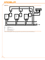
Figure 2.1
LEGEND
A
B
C
D
E
E
t ransformer 230/24 V AC
ignition transformer
t erminal block with fuse
limit thermostat
c ontroller
D
C
A
B
Electrical panel.
9
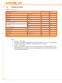
2.4TECHNICAL DATA
Table 2.1 – Technical data.
TECHNICAL CHARACTERISTICS
appliance category
appliance type
gas
thermal capacity
thermal power
gas consumption (1)
efficiency
gas supply pressure
gas fitting dia.
fumes/combustion air fitting dia.
electrical power
electrical power absorption
fuse
operating temperature (2)
air flow (3)
thermal differential
air throw (4)
sound level at 6 m
sound level at 6 m
weight
Technical data.
unit of measurement
natural (methane)
nominal
nominal
natural (G20)
nominal
natural gas (G20)
air intake
fumes outlet
voltage
TYPE
frequency
nominal
in room
nominal
residual speed > 1m/s
open area
typical installation
-
kW
kW
m3/h
%
mbar
"G
mm
mm
V
50 Hz supply
w
A
°C
m3/h
k
m
dB(A)
dB(A)
kg
B15
I2H
C13-C33-B23-C63-C53
G20
15
13,8
1,59
92
20
3/4 F
80
80
230
single-phase
50
160
3.15
0 ÷35
1900
21
12
40
52
28
Notes:
1. At 15 °C - 1013 mbar.
2. WARNING: The operating temperature IN THE ROOM is 0 °C/+35 °C; The operating
temperature OF THE APPLIANCE’S COMPONENTS is 0 °C/+60 °C;
3. At 20 °C - 1013 mbar.
4. Values measured in an open area; in a real installation, the thermal flow may reach
GREATER distances than those given here (depending on the height of the ceiling
and its thermal insulation).
10
Installation, user and maintenance manual – Series B15 Generators
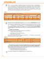
2.5DIMENSIONS
Figure 2.2
LEGEND
1
2
3
4
A
B
C
fumes outlet fitting
combustion air intake fitting
power cable inlet
gas fitting
front view
side view
rear view
Series B15 dimensions.
11
12
Installation, user and maintenance manual – Series B15 Generators
3INSTALLATION
3.1GENERAL INSTALLATION INSTRUCTIONS
T he installation must be done, as instructed by the manufacturer, by professionally qualified personnel.
• Professionally
qualified personnel is defined as those possessing specific technical competence in the residential heating equipment sector. Contact ROBUR S.p.A.
Presales (tel. +39.035.888.111) for any further information.
• Incorrect installation may cause damage to persons, animals or things, for which
the manufacturer is not liable.
• The installation must be done in accordance with established local and national
regulations, in particular:
• Italian Ministerial Decree of 12 April 1996 containing fire prevention regulations regarding the design, construction and operation of heating systems
supplied with gas fuel;
• Italian Decree n. 412/93 governing the design, installation, operation and
maintenance of heating systems;
• Italian Decree n. 551/99 which introduces certain modifications to D.P.R. n.
412/93;
• Italian Law n. 46/90 and its actuating regulation (D.P.R. 447/91) regarding the
safety of heating systems;
• UNI CIG 7129 governing the installation of appliances supplied with natural
gas;
• Italian Law n. 186 of 1 March 1968 regarding the installation of electrical
systems.
On the basis of the installation design, set out the gas and electrical supply lines, as well as
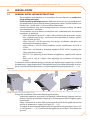
the appliance’s supporting brackets. The appliance may be installed horizontally, at an angle or vertically (air flow downwards), using the optional mounting bracket (3.1 → 13).
•
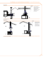
Figure 3.1
Possible installation positions for series B15 generator.
During the installation, observe the following precautions:
• Unpack the appliance, and check it for damage suffered during shipping; each appliance is factory tested before shipping; if it is damaged, notify the shipping agent
immediately.
• Allow a clearance of at least 300 mm between the back of the appliance and the
wall for an adequate air supply (see Figure 3.2 → 15).
• The optimal recommended height from the ground of the generator’s base is 2.5
m (see Figure 3.2 → 15). Do not install the appliance at less than 2.20 m above the
ground.
13
•
•
•
cut-off valve and three-piece coupling must be fitted on the gas supply.
A
Check that there is an adequate mains gas supply. In particular: make sure that the
gas mains pressure, with the appliance operating, is set to 20 mbar (204 mm H2O)
with an admissible range of 17 mbar to 25 mbar (G20 natural gas supply).
Hook the appliance up as shown in the installation wiring diagram (see Figure
3.11 → 24), and make sure the power supply is rated at 230 V 1N - 50Hz. Make
sure that:
• the electricity mains specifications correspond to the specifications on the
nameplate;
• the cable is of the type H05 VVF 3x1.5 mm2 with a maximum external diameter
of 8.4mm;
• ensure that the ground cable is longer than the live cables. In this way it will be
the last wire to be pulled away if the mains cable should accidentally be pulled,
and will thus guarantee the ground connection.
The electrical safety of the appliance is guaranteed only when it is correctly connected to
an efficient grounding system, executed in accordance with current safety regulations.
Do not use gas pipes to ground electrical appliances.
•
•
•
T he appliance must be connected to the mains cable via a two-pole switch with
minimum air gap 3 mm. A two-pole switch is one which opens both the phase and the
neutral contacts. Thus both contacts will be open when the switch is opened.
It is obligatory to equip the installation with a room thermostat connected to
the appliance as shown in the installation wiring diagram (see Figure 3.11 → 24).
Locate the thermostat (or its sensor) around 1.5 m off the floor, shielded from
draughts, direct sunlight, direct heat sources (lamps, the appliance’s hot air output,
etc.) and preferably NOT on an external wall, as this will compromise its temperature reading and hence the operation of the installation. THIS PREVENTS UNDESIRABLE OPERATING CYCLES AND ENSURES OPTIMAL HEATING COMFORT IN
THE ROOM.
As an alternative to the room thermostat, use one of the accessory adjustment and
programming units.
The control cables (especially those connected to the wall panel and temperature sensors)
must be protected from interference generated by power cables. This can be achieved,
for example, by shielding the cables or routing them through ducts separate from power
cables.
•
14
F or best results, comfort and efficiency, observe the following rules:
• make sure that the air flow is not directed towards persons (adjust its direction
with the grille fins)
• take any obstacles into account (columns, etc.).
• fro better heat distribution, in multiple appliance installations, provide alternating hot air flows (see Figure 3.3 → 15).
Installation, user and maintenance manual – Series B15 Generators
Figure 3.2
Min 400
300
350
Min 200
A
A
Min 2,5 m
2,2 ÷ Max
3,0 3,5
[m]m
(min/max)
Clearances: minimum clearance required for installation.
Figure 3.3
Example of generator positioning.
3.2SIZING AND INSTALLING THE COMBUSTION AIR/FUMES EXHAUST
TUBES
Series B15 hot air generators can be installed in one of the following ways.
15
•
•
•
•
•
T ype B23 installation: this type has the combustion air intake inside the room and
the fumes exhaust outdoors via a dedicated tube, which may be either horizontal
or vertical. In this case, the appliance is not sealed off from the room (see Figure
3.5 → 17).
Type C13 installation: The fumes exhaust and the air intake are routed in coaxial or
separate horizontal tubes (or wall-mounted, see Figure 3.6 → 19). In this case, the
appliance is sealed off from the room.
Type C33 installation: the fumes exhaust and the air intake are routed in coaxial or
separate vertical tubes (or roof-mounted, see example C33 in Figure 3.7 → 19). In
this case, the appliance is sealed off from the room.
Type C53 installation: the fumes exhaust and the air intake are routed in separate
tubes which exit outside the building and at a distance from each other. This type
of installation enables implementation of air intake, for example, with horizontal
tubes (or wall-mounted) behind the appliance, and the fumes exhaust distant from
the appliance with a horizontal or vertical tube (or roof-mounted, see example C53
in Figure 3.7 → 19). In this case, the appliance is sealed off from the room.
Type C63 installation: this type enables the implementation of fume/air installations using commercially available tubes, bends and terminals (homologated).
Furthermore, it enables the use of tubes of diameter greater than 80 mm: fro example when very long air/fumes systems are required. In this type of system, the
calculation of the sir/fumes system requires the data provided by the tubes manufacturer, as well as the composition, flow rate and temperature of the fumes themselves (see Table 3.1 → 17).
In any case, always use tubes which are homologated for the type of installation in
question. ROBUR S.p.A. can provide homologated rigid tubes, coaxial tubes and
terminals.
In order to dimension the system of tubes, you must calculate the total pressure drop of
the system.
The total admitted pressure drop is given in Table 3.1 → 17. The pressure drops of the fumes,
air and coaxial tubes supplied by ROBUR, are given in Table 3.2 → 17 (for dia. 80 and 100).
The pressure drops of external terminals need not be considered as they are negligible.
When designing the system, check that the sum of pressure drops of the system of tubes
is less than the maximum pressure drop permitted for the appliance (see Table 3.1 → 17).
The following pages give an example calculation of the pressure drop.
For the maximum admitted lengths (APPROXIMATE) for the air and fumes tubes, depending on the type of installation in question, refer to Table 3.3 → 18 and the note following
it.
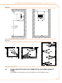
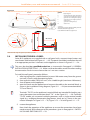
If the horizontal fumes tubes are longer than 1 metre, to prevent condensation returning to the appliance, the tube must be installed at a downwards slope of 2 or 3 cm per
metre of length (see Figure 3.4 → 17). Furthermore, for a correct installation of the external fumes exhaust and air intake terminals, observe the instructions given in Figure
3.8 → 20.
16
Installation, user and maintenance manual – Series B15 Generators
Figure 3.4
LEGEND
p(%)
t ube slope *
* slope to be provided: -2% or -3% (downwards).
example:
slope (downwards) of 2 cm per metre or 3 cm per metre
p(%)
horizontal tube slope.
If the fumes tubes are vertical, to prevent condensation from returning to the appliance,
equip the base of the vertical tube with a "T" junction to collect the condensate (see example "B" in Figure 3.5 → 17).
Figure 3.5
LEGEND
A
2
B
B15
1
2
3
t ype B23 installation with horizontal exhaust (or wall-mounted)
[ B15 generator: seen from above]
t ype B23 installation with vertical
exhaust (or roof-mounted)
[ B15 generator: side view]
c ombustion air intake
f umes exhaust
c ondensation outlet
2
B15
1
A
B
3
B23 type installations: with wall-mounted exhaust and roof-mounted exhaust.
Table 3.1
DATA FOR CALCULATING THE AIR/FUMES SYSTEM WITH COMMERCIALLY AVAILABLE TUBES
CO2 content of fumes [%] (with
Fumes mass flow rate [kg/h]
G20 gas)
175
25,9
9,2 ÷ 9,4
Data for calculating the air/fumes system with commercially available tubes.
Fumes outlet temperature [°C]
Admitted pressure drop [Pa]
60
Table 3.2
PRESSURE DROP OF DIA. 80 COMPONENTS
tube [Pa/m]
90° bend [Pa]
PRESSURE DROP OF DIA. 100 COMPONENTS
coaxial [Pa]
tube [Pa/m]
90° bend [Pa]
coaxial [Pa]
wall
roof
fumes air
fumes air
fumes
air
fumes
air
roof O-SCR009
O-SCR007
O-SCR008
0,7
0,4
1,0
0,9
1,6
2,0
0,2
0,2
0,35
0,25
1,0
Dati per il calcolo del sistema aria/fumi con condotti Ø 80 o Ø 100 forniti da Robur Spa.
17
Each "T" junction increases the effective length of the tube to which it is mounted by 3
metres. For example, if the junction is fitted to a 2 metre fumes tube, when calculating
the pressure drop you must deem the total length of the tube to be 5 metres. Each 5°
bend increases the effective length of the tube to which it is mounted by 1.2 metres. For
example, if the bend is fitted to a 2 metre air tube, when calculating the pressure drop
you must deem the total length of the tube to be 3.2 metres.
Table 3.3
APPROXIMATE ADMITTED MAXIMUM LENGTHS [m] - by TYPE of installation
B23
C13
separate
fumes tube
coaxial wall-mounted
tubes
dia. 125
dia. 80
dia. 80
dia. 180 O-KTC004
O-SCR007
Horizontal
Vertical
dia. 80 tubes
dia. 130 tubes
fumes
fumes
air/fumes
air/fumes
air/fumes
30
30
25+25
20+20
N/A
Approximate maximum lengths.
C33
C53
separate
tubes
coaxial roof-mounted
dia. 125
O-SCR008
dia. 80 tubes
air/fumes
25+25
dia. 150 O-SCR009 dia. 210 O-KTC001 dia. 80
dia. 100 tubes
air/fumes
30+30
dia. 130 tubes
air/fumes
N/A
air/fumes
1+25
The above maximum admitted lengths are to be considered APPROXIMATE and apply
to installations in which the tubes (air and fumes) are routed linearly as shown in Figure
3.5 → 17; Figure 3.6 → 19 and Figure 3.7 → 19. If this condition does not apply, you
must calculate the pressure drop (see "EXAMPLE CALCULATION" below): the installation
is permitted only if the total pressure drop is less than the admitted pressure drop
(see 3.1 → 17).
EXAMPLE CALCULATION
We are to install a B15 with separate tubes, dia. 80, as follows:
• 7 metres of fumes tube dia. 80;
• 2 90° bends dia. 80 on the fumes tube;
• 6 metres of air tube dia. 80.
We can now calculate the pressure drop (see Table 3.4 → 18), bearing in mind that the
total admitted pressure drop is 60 Pa.
Table 3.4
COMPONENT
Dia. 80 fumes tube
90° bends
Dia. 80 air tubes
TOTAL PRESSURE DROP
Example numerical calculation.
Quantity [m]
7
2
6
Pressure drop [Pa/m]
x
x
x
0,7
1,0
0,4
=
=
=
=
Pressure drops [Pa]
4,9
2,0
2,4
9,3
The total pressure drop is less than the admitted pressure drop (9.3 Pa less than
the maximum admitted figure of 60 Pa) and hence the installation is PERMITTED.
If the installation had turned out to be not permitted due to excessive pressure drop, we
could have adopted one of the following measures:
• reduce the length of the air/fumes tubes;
• increase the diameter of the tubes to dia. 100.
For special installations, phone ROBUR Presales at +39.035.888.111.
18
Installation, user and maintenance manual – Series B15 Generators
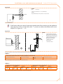
Figure 3.6
LEGEND
C13
V1
E1
E2
A
F
C
13 type installations
g
enerator, seen from above
e xample with separate
wall-mounted ducts
e xample with coaxial wallmounted duct
c ombustion air intake
f umes exhaust
C13 type installations.
Figure 3.7
LEGEND
V1
V2
A
F
S.C
C33
C53
g
enerator, front view
g
enerator, side view
c ombustion air intake
f umes exhaust
c ondensation outlet
t ype C33 installation
t ype C53 installation
C33 and C53 type installations.
19
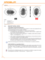
Figure 3.8
B
C
A
IN
LEGEND
IN
OUT
A
B
C
OUT
OUT
IN
IN
OUT
combustion air intake
fumes exhaust
recommended position (OK)
admitted position (OK)
NOT admitted position (NO)
Wall terminal position.
3.3BRACKET INSTALLATION
USING ROBUR SUPPORTING BRACKETS
ROBUR S.p.A. provides easy to install mounting brackets as accessory equipment for the
series B15 generator [accessory code: O-STF019].
To install the appliance using the Robur (O-STF019) mounting bracket:
1. install the bracket to the appliance as explained in the instructions supplied with
the O-STF019 mounting bracket itself;
2. follow the instructions given in Paragraph 3.1 GENERAL INSTALLATION INSTRUCTIONS → 13 and Figure 3.2 → 15;
3. drill n. 4 holes into the wall (through its entire thickness) in line with the 4 holes in
the wall plate supplied with the Robur bracket;
4. secure the generator’s mounting bracket to the wall using the counterplate supplied with the Robur bracket: secure the counterplate (located on the outside of
the wall) to the wall plate (on the inside of the wall) with 4 M10 bolts.
Observe the warnings given in the Robur O-STF019 bracket’s assembly instructions.
USING SHELVES (not supplied by Robur)
If he opts not to use Robur mounting accessories, the installer must not only observe the
instructions given in Paragraph 3.1 GENERAL INSTALLATION INSTRUCTIONS → 13 and
Figure 3.2 → 15, but must also employ a shelf which satisfies the specifications of Figure
3.9 → 21.
The shelf must be sufficiently robust for its intended use and able to support the weight
of the appliance (see Table 2.1 Technical data. → 10) plus its own.
20
Installation, user and maintenance manual – Series B15 Generators
Figure 3.9
LEGEND
Ssupporting plate
P
w
all-mounted plate (and counterplate)
a
g
enerator base mounting hole spacing
c
g
enerator rear mounting hole spacing
b
g
enerator base/rear support plane line
of intersection
v
g
enerator mounting bolts (*)
D
d
etail of "b-c"
176 mm
D
v
a
b
S
v
* use (n. 4):
spring washer 6.4x12.5 UNI 6592-69-R4O galvanised
washer D.6 UNI 8842 A6 galvanised
bolts UNI EN 24017-M6x20-8.8 galvanised
12 mm
MIN 300 mm
90 mm
b
430 mm
c
340 mm
a
D
P
Installation with supporting bracket provided by installer.
3.4INSTALLING THE WALL PANEL
Series B15 appliances are supplied with a wall panel with: summer/winter button and
reset button with lockout led (Figure 4.1 → 29). The panel should be installed on the wall
in an appropriate position. It connects to the appliance as shown in Figure 3.11 → 24.
This must be done by a qualified technician, as instructed in Paragraph 3.1 GENERAL
INSTALLATION INSTRUCTIONS → 13 . Make sure that the cables are not live when making
the connection. Each wire must have at least a 1 mm cross section.
To install the wall panel, proceed as follows:
1. after having found a suitable location (at most 100 metres away from the generator itself ), install it with the expansion bolts;
2. then route the cable (FROH 8x1 mm2) of a suitable length (maximum 100 metres);
3. shut off power to the appliance;
4. open the hatch on the appliance and connect the cable to the terminal block, as
shown in the installation wiring diagram, Figure 3.11 → 24 (see connection details
"E/I" and "Reset");
Terminals "Z9-Z9" on the appliance’s terminal block are intended for hooking up a
room thermostat (see connection detail "T.A" - in the Figure 3.11 → 24). Terminals
"Z9-Z9" enable you to control multiple generators with a single external enable
signal (e.g.: analogue thermostatic programmer, clock, etc.) as shown in the connection examples in Figure 3.12 → 25, Figure 3.13 → 26 and Figure 3.14 → 27.
5. restore the appliance.
Now check the operation of the appliance to ensure the connections have been
made correctly. With reference to the procedures given in Paragraph 4.1 SWITCHING ON AND SWITCHING OFF → 29:
21
6. a ctivate FAN ONLY mode;
7. activate HEATING mode;
8. in HEATING mode, close the gas supply line and check that the lockout led on the
reset button "B" lights up after a few seconds (detail "3" - Figure 4.1 → 29);
9. now check that when you open teh gas cock and press reset button "B", the lockout
led goes out and the generator starts up again;
If the appliance behaves in any other way than specified in the procedures in Paragraph
4.1 SWITCHING ON AND SWITCHING OFF → 29 or exhibits any anomalous behaviour,
this indicates a possible wiring error. Check the connections and if the anomaly persists,
contact your local TAC or Robur Spa Service (tel. +39.035.888.111).
CONTROLLING MULTIPLE APPLIANCES WITH A SINGLE EXTERNAL ENABLE SIGNAL
Terminals "Z9-Z9" enable you to control multiple generators with a single external enable
signal (e.g.: analogue thermostatic programmer, clock, etc.).
There are three possible control options as shown in Figures 3.12 → 25, 3.13 → 26 and
3.14 → 27:
• control of multiple appliances with a single programmer and multiple room
thermostats;
• control of multiple appliances with a single programmer and a single room thermostats (with multiple relays);
• control of multiple appliances with a single programmer and a single room thermostats (with a single relay).
3.5SETTING THE GAS VALVE
For correct operation of series B15 generators, the gas valve must be set to the values
given in Table 3.5 → 23. The appliance is shipped with the gas valve already set.
If further adjustment should be necessary, proceed as explained below (see Figure
3.10 → 23).
The adjustment must be done by professionally qualified personnel. ROBUR S.p.A. has
a network of Assistance Centres which can be contacted via your reseller, area agent, or
by phoning ROBUR S.p.A. Customer Assistance tel. +39.035.888.111.
You will need: the appliance connected to the power/gas supply. Necessary equipment and materials.
1. C
onnect a pressure gauge to pressure fitting "B", after having slackened off the seal
screw.
If using a differential gauge, connect gas valve fitting "B" to the gauge’s + (positive)
terminal.
2. T urn on the appliance and wait for the flame to reach a steady state (around 2
minutes).
3. Operation with hatch open: remove its cap with a screwdriver and adjust offset
adjuster screw "A" (you will need a 4 mm allen key) to the nominal value given in
3.5 → 23.
22
Installation, user and maintenance manual – Series B15 Generators
Table 3.5
OFFSETS
OFFSET
nominal
Offsets.
[mbar]
-0,1
[Pa]
-10
1. C
heck that the CO2 percentage is as given in 3.1 → 17. If it is not, adjust the offset
again until the CO2 percentage is as given in 3.1 → 17.
2. Turn the appliance off and back on again two or three times to check that the new
setting is stable.
3. Disconnect the pressure gauge and screw pressure fitting "B" seal screw back in
again.
4. Restore the appliance, making sure to fit the cap onto screw "A".
Figure 3.10
LEGEND
A
B
C
A
B
o ffset adjuster screw
o utlet gas pressure fitting
inlet gas pressure fitting
C
Gas Valve.
23
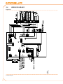
3.6WIRING DIAGRAMS
LEGEND
vedi disegno
Figure 3.11
Installation diagram.
24
Installation, user and maintenance manual – Series B15 Generators
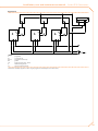
Figure 3.12
LEGEND
P
TA
RL1-2-3
GR
L-N
A
Z9
programmer
room thermostat
programmed control relay
ground
single-phase line (230 V - 50 Hz)
wall-mounted generator
generator internal terminals
Installation of multiple appliances with a single programmer and multiple room thermostats.
25
Figure 3.13
LEGEND
P
TA
RL1-2-3
GR
L-N
A
Z9
programmer
room thermostat
programmed control relay
ground
single-phase line (230 V - 50 Hz)
wall-mounted generator
generator internal terminals
Installation of multiple appliances with a single programmer and a single room thermostat (solution with multiple relays).
26
Installation, user and maintenance manual – Series B15 Generators
Figure 3.14
LEGEND
P
TA
RL
GR
L-N
A
Z9
programmer
room thermostat
programmed control relay
ground
single-phase line (230 V - 50 Hz)
wall-mounted generator
generator internal terminals
Installation of multiple appliances with a single programmer and a single room thermostat (solution with a single relay).
27
28
Installation, user and maintenance manual – Series B15 Generators
4USE AND OPERATION
4.1SWITCHING ON AND SWITCHING OFF
The first start up must be done by professionally qualified personnel.
Before starting up the generator, have it checked by professionally qualified personnel:
•
•
•
•
t he electricity and gas mains specifications must correspond to the specifications
on the nameplate;
the calibration must be compatible with the generator’s power rating;
the fumes exhaust tubes are operational;
the combustion air and fumes exhaust must be in accordance with established
legislation.
WINTER MODE
To activate HEATING mode, proceed as follows:
You will need: the appliance connected to the power/gas supply.
1.
2.
3.
4.
5.
6.
7.
8.
S et the room thermostat to its maximum.
Check that the gas valve is open.
Power up the appliance with the master power switch.
Set button "A" (summer/winter button) to Winter ("snowflake" ICON; detail "1" - Figure 4.1 → 29).
After the pre-plunge time (around 40 seconds), the gas solenoid valve opens and
the burner ignites.
The appliance’s controller keeps the valve open so long as it detects the flame.
If it does not, the controller locks out the appliance and turns on the lockout led
on the reset button "B" (detail "3" - Figure 4.1 → 29): if this occurs, press the reset
button "B".
Once he burner has ignited, set the room thermostat to the desired value.
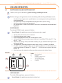
Figure 4.1
A
LEGEND
Asummer/winter button
Breset button
1"snowflake" icon (winter position)
[ for heating operation]
2
" sun" icon (summer position)
[ for ventilation operation only]
3
lock-out led
B
1
3
2
Wall panel.
SWITCHING OFF
To switch off the appliance, proceed as follows:
You will need: the appliance operating (switched on).
29
•
Set the room thermostat to its minimum.
The burner will go out, whereas the fan will continue running so long as the appliance is
still warm.
Do not switch off the appliance by shutting off its power supply as this can severely damage it by stopping the fan and tripping the limit thermostat (automatic reset).
The limit thermostat ONLY trips during malfunctions. Before resetting it, troubleshoot the
problem (in this case, overheating). If it trips frequently, contact ROBUR TAC.
SUMMER MODE
To activate FAN ONLY mode, proceed as follows:
You will need: the appliance connected to the power/gas supply.
1. C
lose the gas valve and check that the appliance is powered up.
2. Set button "A" (summer/winter button) to Summer ("sun" ICON; detail "2" - Figure
4.1 → 29): this runs only the fan, to refresh the air in the room.
PROLONGED PERIODS OF DISUSE
If the appliance is put out of service for a LONG TIME (i.e., seasonal disuse), proceed as
follows:
• Switch the appliance off and wait for the fan to stop running.
• Close the gas cock upline of the appliance.
• If you have no intention of using SUMMER mode, switch off the power supply to
the appliance with the master power switch on the power cable.
SWITCHING THE APPLIANCE BACK ON: after a long period of disuse, it may be necessary to start up the appliance several times, due to air in the tubes.
30
Installation, user and maintenance manual – Series B15 Generators
5SERVICE AND ASSISTANCE
5.1MALFUNCTIONS
Before taking any particular measures, always check that:
• the power supply is present: 230 V ± 10% 50 Hz with an effective ground plant;
• the gas supply is present;
• the gas pressure and flow rate must be in the range specified by the
manufacturer.
A lower pressure than that indicated by the manufacturer corresponds to an insufficient
gas supply. The causes may include:
• insufficient gas flow meter;
• excessive length/number of bends in the gas pipe for the dia. in use.
Only if the appliance passes these basic checks, proceed to troubleshoot the problem in
question.
Before opening the appliance’s side hatch to access its electrical panel, SHUT OFF POWER
to the appliance with the master power switch on its power cable.
Table 5.1
LED ON
DESCRIPTION OF MALFUNCTION
steady
flashing (on: 4 sec; off:
1 sec)
flashing (on: 1 sec; off:
4 sec)
malfunction NOT
indicated by wall panel
CAUSE
• The ignition electrodes are broken or badly
located.
• The detection electrode is broken or badly
located, or is in contact with the appliance’s metal
Flame locked out due to failure to ignite frame.
burner
• Circuit board/electrical connection failure.
• Gas valve/electrical connection failure.
• Ineffective ground plant.
• Air in the gas hose or no gas supply.
• Incorrect gas valve setting.
• Dirt accumulation on the air intake.
Limit thermostat tripped due to
• Delivery outlet blocked.
overheated heat exchangers.
• Fan malfunction.
• Generator power failure during operation.
• Poor electrical connections.
Blower failure.
• Blower motor malfunction.
• Poor performance.
The burner switches off and does not
• The room thermostat is positioned in such a way
start again even if the room temperature as to be affected by sources of heat or the flow
requires it to do so.
of hot air.
RESPONSE
Reposition or replace the electrodes.
Reposition or replace the electrode.
Replace the circuit board.
Replace the gas valve.
Restore the ground plant.
Vent the air in the gas hose.
Reset the gas valve.
Once the cause of the malfunction has been
identified and eliminated, press button B on the
wall panel (see figure 4.1 → 29).
Once the cause of the malfunction has been
identified and eliminated, reset the limit
thermostat pressing button B on the wall panel
(see figure 4.1 → 29).
The malfunction indication is automatically reset
once the cause of the malfunction has been
eliminated.
Reposition the room thermostat.
Malfunctions.
5.2CLEANING THE REMOVABLE BURNER
The burner of series B15 generators can be removed: this is especially useful for
cleaning.
The burner should be cleaned every two years. If the appliance is installed in especially
dirty conditions (in the presence of welding and grinding equipment or other machinery) clean the burner once a year before the start of the winter season.
The burner must be removed and cleaned by professionally qualified personnel. Incorrect or careless assembly of the gas circuit can result in hazardous gas leaks along the
circuit, especially in the areas directly affected.
To clean the burner, proceed as explained below (see Figure 5.1 → 32).
31
You will need: generator powered off, with master power switch set to "OFF" and gas
valve set to "CLOSED".
1.
2.
3.
4.
5.
6.
pen the generator’s hatch.
O
Undo the hexagonal ring nut connecting the gas pipe to the nozzle mount fitting.
Move the gas pipe aside and remove the nozzle.
Undo the four bolts securing the blower screw.
Remove the deflector and its gasket.
Slacken off the four bolts securing the burner and when it is resting on the base,
completely unscrew it and remove it.
7. Fit a tube into the burner (do not bend, damage or tamper with the deflector inside the burner), and exert upwards pressure to extract the burner.
8. Clean the burner with compressed air.
9. Refit the burner (with its cavity uppermost).
10. Fit the lower bolts, then the upper ones and then tighten them all down in a crosswise pattern.
11. Refit the diaphragm and its gasket.
12. Fit the blower screw with its four bolts.
13. Fit the nozzle and its gasket into the nozzle mount.
14. Tighten down the hexagonal ring nut connecting the gas pipe to the nozzle mount
fitting.
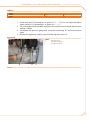
Figure 5.1
LEGEND
* use a 30 mm wrench on the gas tube connection nut.
Removing the gas tube.
32
Installation, user and maintenance manual – Series B15 Generators
33
Robur Mission
Robur Spa
tecnologie avanzate
per la climatizzazione
Via Parigi 4/6
24040 Verdellino/Zingonia (Bg) Italy
T +39 035 888111 F +39 035 884165
www.robur.it [email protected]
Revision: A Code: D-LBR595 10 MED SDC 005 19/11/2010
Robur is dedicated to dynamic progression
in research, development and promotion
of safe, environmentally-friendly, energy-efficiency products,
through the commitment and caring
of its employees and partners.